
WR12DAF2 - Tower HITACHI - Free user manual and instructions
Find the device manual for free WR12DAF2 HITACHI in PDF.


| Product Type | Cordless Drill/Driver |
| Brand | Hitachi (Metabo HPT) |
| Model | WR12DAF2 |
| Voltage | 12V |
| Battery Type | Lithium-ion (12V slide-type) |
| Chuck Type | Keyless, 3/8" (10 mm) |
| Max Torque | 250 in-lbs (28 Nm) |
| Speed Settings | Variable speed, 0-600 RPM |
| Clutch Positions | 18+1 (drill mode) |
| Weight (with battery) | 2.5 lbs (1.1 kg) |
| Dimensions (LxWxH) | 7.5 x 8.5 x 2.5 in (190 x 216 x 64 mm) |
| Power Source | Battery pack (12V Li-ion) |
| Charger Included | Yes (UC12SL2) |
| LED Work Light | Yes |
| Belt Clip | Included (removable) |
| Warranty | 2 years limited |
| Included Accessories | Battery, charger, belt clip, #2 Phillips bit |
| Motor Type | Brushed |
| Maintenance | Clean with dry cloth; keep air vents free of debris |
| Safety | Wear safety glasses; do not immerse in water |
| Spare Parts & Repairability | Parts available through authorized Hitachi service centers |
Frequently Asked Questions - WR12DAF2 HITACHI
User questions about WR12DAF2 HITACHI
0 question about this device. Answer the ones you know or ask your own.
Ask a new question about this device
Download the instructions for your Tower in PDF format for free! Find your manual WR12DAF2 - HITACHI and take your electronic device back in hand. On this page are published all the documents necessary for the use of your device. WR12DAF2 by HITACHI.
USER MANUAL WR12DAF2 HITACHI
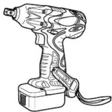
Cordless Impact Driver/Wrench
natural_image
Line drawing of a handheld electric drill press with attached cable (no text or symbols)WH12DAF2
natural_image
Line drawing of a handheld electric drill press tool with attached power strip (no text or symbols)WR12DAF2
Read through carefully and understand these instructions before use.
natural_image
Technical line drawing of a mechanical component with labeled parts (no text or symbols present)2
3
4
6
7
8
natural_image
Illustration of a hand holding a tool with an arrow indicating motion (no text or symbols)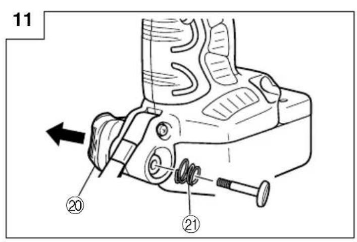
17
| English Deutsch | Ελληνικά Polski | |||
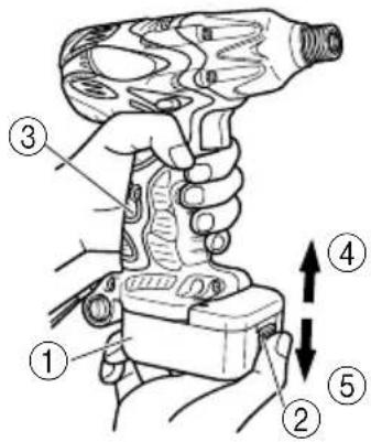
| 1 | 14.4 V Rechargeable battery | 14,4 V aufladbare Batterie | 14,4V Επαναφορτιζόμενη μπαταρία | Akumulator 14,4 V |
| 2 | Latch | Verriegelung | Μάνδαλο | Zapadka |
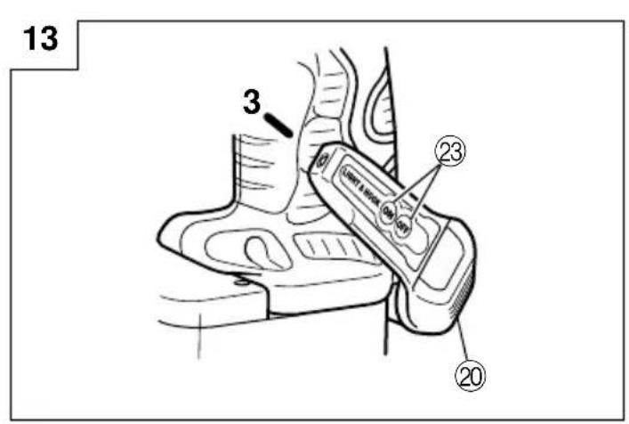
| 3 | Handle | Handgriff | Χερούλι | Rączka |
| 4 | Insert | Einsetzen | Εισχωρήστε | Włóż/wprowadź |
| 5 | Pull out | Herausziehen | Τραβήξτε έξω | Wyciągnij |
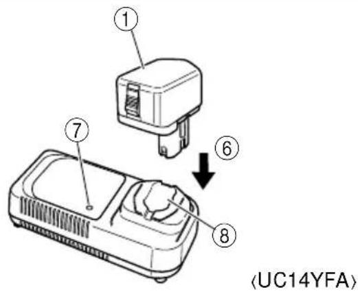
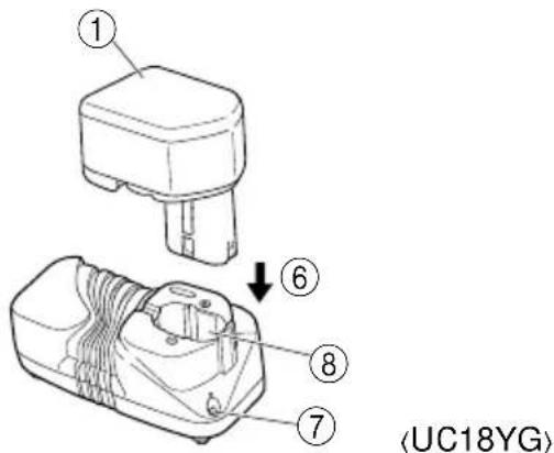
| 6 | Insert | Einsetzen | Εισχωρήσσετε | Włóż/wprowadź |
| 7 | Pilot lamp | Kontrollampe | Δοκιμαστική λάμπα | Lampka kontrolna |
| 8 | Hole for connecting the rechargeable battery | Anschlußloch für Ladebatterir | Τρύπα για την σύνδεση της επαναφορτιζόμενης μπαταρίας | Otwór wsuwowy akumulatora |
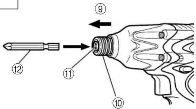
| 9 | Movement | Bewegung | Κίνηση | Ruch |
| 10 | Guide sleeve | Führungsmanschette | Οδηγητικός βραχίονας | Tuleja prowadnicy |
| 11 | Hexagonal hole in the anvil | Sechskantloch in der Schabotte | Εξάγωνη τρύπα στον άκμονα | Otwór sześciokątny w kowadle |
| 12 | Driver bit | Dreherspitze | Λεπίδα κίνησης | Wkrętak |
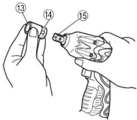
| 13 | Hexagonal socket | Sechskantbuchse | Μακριά υποδοχή | Gniazdo sześciokątne |
| 14 | Groove | Nut | Αυλάκωση | Rowek |
| 15 | Anvil | Schabotte | Άκμονας | Kowadło |
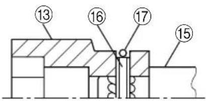
| 16 | Pin | Stift | Πείρος | Kołek |
| 17 | Ring | Ring | Δακτύλιος | Pierścień |
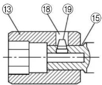
| 18 | Hole | Öffnung | Τρύπα | Otwór |
| 19 | Plunger | Preßkolben | Έμβολο | Trzpień ruchomy |
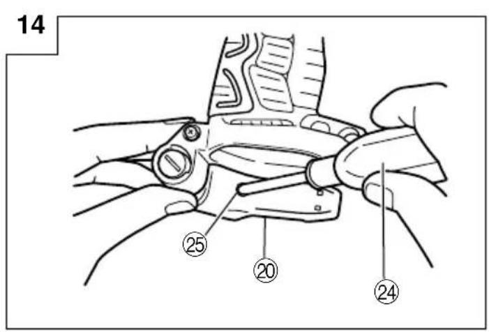
| 20 | Hook | Haken | Γάντζος | Hak |
| 21 | Spring | Feder | Ελατήριο | Sprężyna |
| 22 | Larger diameter faces away | Der große Durchmesser weist zur anderen Seite | Η μεγαλύτερη διάμετρος βλέπει προς άλλη κατεύθυνση | Większa średnica jest odwrócona |
| 23 | Switch | Schalter | Διακόπτης | Przełącznik (włącznik/ wyłącznik) |
| 24 | Phillips-head screwdriver | Kreuzschlitzschraubenzieher | Κατσαβίδι κεφαλής Phillips | Wkrętak Philipsa/ zgniazdkiem krzyżykowym |
| 25 | Screw | Schraube | Βίδα | Śruba/wkręt |
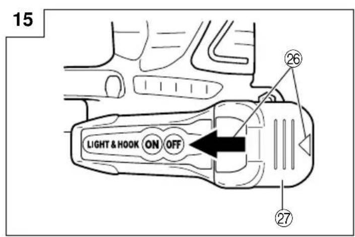
| 26 | Arrow | Pfeil | Βέλος | Strzałka |
| 27 | Hook cover | Hakenabdeckung | Κάλυμμα αγκίστρου | Pokrywa haka |
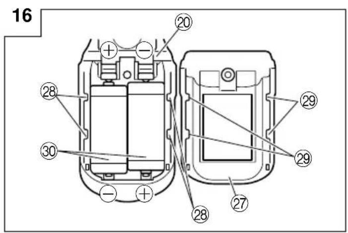
| 28 | Indentation | Einkerbung | Αυλάκωση | Nacięcie |
| 29 | Protuberance | Vorsprung | Προεξοχή | Wypukłość |
| 30 | AAAA batteries | Batterien der Größe AAAA | AAAA μπαταρίες | Baterie AAAA |
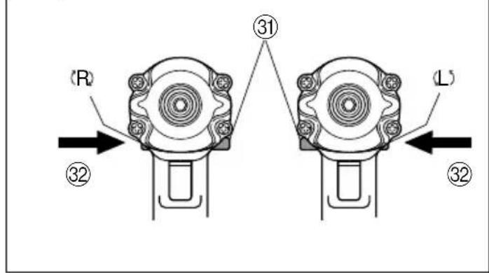
| 31 | Push button | Druckknopf | Κουμπί ώθησης | Przycisk |
| 32 | Push | Drücken | Σπρώξε | Wcisnąć |
| Magyar Čeština Türkçe Русский | ||||
| 1 | 14,4 V-os tõlthetõ akkumulátor | 14,4V Akumulátor | 14,4 V Şarj edilebilir batarya | 14,4 В аккумуляторная батарея |
| 2 | Retesz | Zámek | Mandal | Фиксатор |
| 3 | Markolat | Držadlo | Kol | Рукоятка |
| 4 | Bedugni | Zasunout | Yerleştirin | Вставить |
| 5 | Kihúzni | Zatáhnout | Çekin | Вытащить |
| 6 | Bedugni | Zasunout | Yerleştirin | Вставить |
| 7 | Jelzőlámpa | Indikátor | Kılavuz lamba | Контрольная лампа |
| 8 | Nyílás a tõlthetõ akkumulátor csatlakoztatásához | Otvor pro zasunutí akumulátoru | Şarj edilebilir bataryanın takılacağı delik | Отверстие для подключения аккумуляторной батареи |
| 9 | Mozgás | Pohyb | Hareket | Перемещение |
| 10 | Vezetőhüvely | Vodicí objímka | Kılavuz segmanı | Направляющий обод |
| 11 | Hatszögletű nyílás a szárban | Šestihranný otvor v pevné části | Örstekki altigen delik | Шестигранное отверстие в наковальне |
| 12 | Behajtófej | Hrot šroubováku | Tahrik ucu | Насадка шуруповерта |
| 13 | Hatszögletű befogópatron | Šestihranný nástrčkový klíč | Altigen yuva | Шестигранное гнездо |
| 14 | Vájat | Drážka | Yiv | Канавка |
| 15 | Szár | Pevná část | Örs | Наковальня |
| 16 | Csap | Kolík | Pim | Штифт |
| 17 | Gyúrű | Kroužek | Halka | Кольцо |
| 18 | Nyílás | Otvor | Delik | Отверстие |
| 19 | Hengeres csap | Západkový čep | Ítici | Плунжер |
| 20 | Kampó | Páčka | Askı | Крючок |
| 21 | Rúgó | Pružina | Yay | Пружина |
| 22 | A nagyobb átmérő az ellenkező irány felé néz | Větší průměr směřuje ven | Büyük olan çap uzağa bakar | Больший диаметр поворачивается в другую сторону |
| 23 | Kapcsoló | Spínač | Şalter | Выключатель |
| 24 | Keresztfejes (Phillips-) csavarhúzó | Křížový šroubovák | Yıldız başlı tornavida | Отвертка с крестообразной головкой |
| 25 | Csavar | Šroub | Vida | Винт |
| 26 | Nyíl | Šipka | Ok | Стрелка |
| 27 | A kampó fedele | Kryt páčky | Askı kapağı | Крышка крючка |
| 28 | Bemélyedés | Prohlubeň | Girinti | Углубление |
| 29 | Kidudorodás | Výstupek | Çıkıntı | Выступ |
| 30 | AAAA méretű szárazelemek | AAAA baterie | AAAA piller | Аккумуляторные батареи AAAA |
| 31 | Nyomógomb | Tlačítko | Kilit iğnesi | Нажимная кнопка |
| 32 | Benyomni | Stisknout | Ítin | Нажать |
GENERAL OPERATIONAL PRECAUTIONS
WARNING! When using battery operated tools, basic safety precautions should always be followed to reduce the risk of fire, leaking batteries and personal injury, including the following.
Read all these instructions before operating this product and save these instructions.
For safe operations:
-
Keep work area clean. Cluttered areas and benches invite injuries.
-
Consider work area environment. Do not expose tools to rain. Do not use tools in damp or wet locations. Keep work area well lit. Do not use tools where there is risk to cause fire or explosion.
-
Keep children away. Do not let visitors touch the tool. All visitors should be kept away from work area.
-
Store batteries or idle tools. When not in use, tools and batteries should be stored separately in a dry, high or locked up place, out of reach of children. Ensure that battery terminals cannot be shorted by other metal parts such as screws nails etc.
-
Do not force the tool. It will do the job better and safer at the rate for which it was intended.
-
Use the right tool. Do not force small tools or attachments to do the job of a heavy duty tool. Do not use tools for purposes not intended.
-
Dress properly. Do not wear loose clothing or jewellery, they can be caught in moving parts. Rubber gloves and non-skid footwear are recommended when working outdoors. Wear protecting hair covering to contain long hair.
-
Use safety glasses. Also use face or dust mask if the cutting operation is dusty.
-
Connect dust extraction equipment. If devices are provided for the connection of dust extraction and collection facilities, ensure these are connected and properly used.
-
Do not abuse the cord (if fitted). Never carry the tool by the cord or yank it to disconnect it from the socket. Keep the cord away from heat, oil and sharp edges.
-
Secure work. Use clamps or a vice to hold the work. It is safer than using your hand and it frees both hands to operate the tool.
-
Do not overreach. Keep proper footing and balance at all times.
-
Maintain tools with care. Keep cutting tools sharp and clean for better and safer performance. Follow instructions for lubrication and changing accessories. Inspect tool cords periodically and if damaged, have it repaired by authorized service facility. Keep handles dry, clean, and free from oil and grease.
-
Disconnect tools. Where the designs permits, disconnect the tool from its battery pack, when not in use, before servicing, and when changing accessories such as blades, bits and cutters.
-
Remove adjusting keys and wrenches. Form the habit of checking to see that keys and adjusting wrenches are removed from the tool before turning it on.
-
Avoid unintentional starting. Do not carry the tool with a finger on the switch.
-
Stay alert. Watch what you are doing. Use common sense. Do not operate the tool when you are tired.
-
Check damaged parts. Before further use of the tool, a guard or other part that is damaged should be carefully checked to determine that it will operate properly and perform its intended function.
Check for alignment of moving parts, free running of moving parts, breakage of parts, mounting and any other conditions that may affect its operation. A guard or other part that is damaged should be properly repaired or replaced by an authorized service center unless otherwise indicated in this handling instructions. Have defective switches replaced by an authorized service facility. Do not use the tool if the switch does not turn it on and off.
- Warning
○The use of any accessory or attachment, other than those recommended in this handling instructions, may present a risk of personal injury.
○Ensure that the battery pack is correct for the tool.
○Ensure that the outside surface of battery pack or tool is clean and dry before plugging into charger.
○Ensure that batteries are charged using the correct charger recommended by the manufacturer. Incorrect use may result in a risk of electric shock, overheating or leakage of corrosive liquid from the battery.
-
Have your tool repaired by a qualified person. This tool is in accordance with the relevant safety requirements. Repairs should only be carried out by qualified persons using original spare parts, otherwise this may result in considerable danger to the user.
-
Disposal of battery Ensure battery is disposed of safely as instructed by the manufacturer.
-
If under abusive conditions, liquid is ejected from the battery, avoid contact If this accidentally occurs, frush with water. If liquid contacts eyes additionally, seek medical help.
PRECAUTIONS FOR CORDLESS IMPACT DRIVER
- This is portable tool for tightening and loosening screws. Use it only for these operation.
- Use the earplugs if using for a long time.
- One-hand operation is extremely dangerous; hold the unit firmly with both hands when operating.
- After installing the driver bit, pull lightly out the bit to make sure that it does not come loose. If the bit is not installed properly, it can come loose during use, which can be dangerous.
- Use the bit that matches the screw.
- Tightening a screw with the impact driver at an angle to that screw can damage the head of the screw and the proper force will not be transmitted to the screw. Tighten with this impact driver lined up straight with the screw.
- Always charge the battery at a temperature of 0 - 40°C.
A temperature of less than 0^ C will result in over charging which is dangerous. The battery cannot be charged at a temperature greater than 40^ C. The most suitable temperature for charging is that of 20 - 25^ C. - Do not use the charger continuously.
When one charging is completed, leave the charger for about 15 minutes before the next charging of battery. - Do not allow foreign matter to enter the hole for connecting the rechargeable battery.
- Never disassemble the rechargeable battery and charger.
-
Never short-circuit the rechargeable battery. Short-circuiting the battery will cause a great electric current and overheat. It results in burn or damage to the battery.
-
Do not dispose of the battery in fire. If the battery burnt, it may explode.
- Do not insert object into the air ventilation slots of the charger. Inserting metal objects or inflammables into the charger air ventilation slots will result in electrical shock hazard or damaged charger.
- Bring the battery to the shop from which it was purchased as soon as the post-charging battery life becomes too short for practical use. Do not dispose of the exhausted battery.
- Using an exhausted battery will damage the charger.
PRECAUTIONS FOR CORDLESS IMPACT WRENCH
- This is a portable tool for tightening and loosening bolts and nuts. Use it only for these operation.
- Use the earplugs if using for a long time.
- One-hand operation is extremely dangerous; hold the unit firmly with both hands when operating.
- Check that the socket is not cracked or broken. Broken or cracked sockets are dangerous. Check the socket before using it.
- Secure the socket with the socket pin and the ring. If the socket pin or ring securing the socket is damaged, the socket may come off from the impact wrench, which is quite dangerous. Do not use socket pins or rings that are deformed, worn out, cracked, or in any other way damaged. Always make sure to install the socket pin and ring in the correct position.
- Check the tightening torque. The appropriate torque for tightening a bolt depends on the material the bolt is made of, its dimensions, grade, etc.
Also, the tightening torque generated by this impact wrench depends on the materials and dimensions of the bolt, how long the impact wrench is applied for the way in which the socket is installed, etc. Also the torque when the battery has just been charged and when it is about to run out are slightly different. Use a torque wrench to check that the bolt has been tightened with the appropriate torque.
- Stop the impact wrench before switching the direction of rotation. Always release the switch and wait for impact wrench to stop before switching the direction of rotation.
- Never touch the turning part. Do not allow the turning socket section to get near your hands or any other part of your body. You could
SPECIFICATIONS
POWER TOOL
| Model WH12DAF2 WR1 | 2DAF2 | |
| No-load speed 0 - 2500 min | -1 | |
| Capacity | M4 - M8 (Small screw)M5 - M12 (Ordinary bolt)M5 - M10 (High tension bolt) | M6 - M14 (Ordinary bolt)M6 - M10 (High tension bolt) |
| Tightening torque | Maximum 110 N·m {1120 kgf·cm}Tightening is M12 high tension bolt (strength grade 12.9), when fully charged at 20°C temp.Tightening time: 3 sec. | Maximum 130 N·m {1330 kgf·cm}Tightening is M12 high tension bolt (strength grade 12.9), when fully charged at 20°C temp.Tightening time: 3 sec. |
| Rechargeable battery | EB1214S: Ni-Cd battery, 12 V (1.4 Ah 10 cells) | |
| EB1220BL: Ni-Cd battery, 12 V (2.0 Ah 10 cells) | ||
| EB1226HL: Ni-MH battery, 12 V (2.6 Ah 10 cells) | ||
| Weight 1.6 kg (EB1214S Installation) | ||
be cut or caught in the socket. Also, be careful not to touch the socket after using continuously it for a long time. It gets quite hot and could burn you.
- Never let the impact wrench turn without a load when using the universal joint. If the socket turns without being connected to a load, the universal joint causes the socket to turn wildly. You could get hurt or the movement of the socket could shake the impact wrench so much as to make you drop it.
- Always charge the battery at a temperature of 0 - 40°C. A temperature of less than 0°C will result in over charging which is dangerous. The battery cannot be charged at a temperature greater than 40°C. The most suitable temperature for charging is that of 20 - 25°C.
- Do not use the charger continuously. When one charging is completed, leave the charger for about 15 minutes before the next charging of battery.
- Do not allow foreign matter to enter the hole for connecting the rechargeable battery.
- Never disassemble the rechargeable battery and charger.
- Never short-circuit the rechargeable battery. Short-circuiting the battery will cause a great electric current and overheat. It results in burn or damage to the battery.
- Do not dispose of the battery in fire. If the battery burnt, it may explode.
- Do not insert object into the air ventilation slots of the charger. Inserting metal objects or inflammables into the charger air ventilation slots will result in electrical shock hazard or damaged charger.
- Bring the battery to the shop from which it was purchased as soon as the post-charging battery life becomes too short for practical use. Do not dispose of the exhausted battery.
- Using an exhausted battery will damage the charger.
MODEL
WH12DAF2:with charger and case WR12DAF2:with charger and case
CHARGER
| Model UC14YFA UC18YG | ||
| Charging time | EB1214S: Approx. 30 min. (at 20°C) | EB1214S: Approx. 30 min. (at 20°C) |
| EB1220BL: Approx. 50 min. (at 20°C) | EB1220BL: Approx. 50 min. (at 20°C) | |
| EB1226HL: Approx. 60 min. (at 20°C) · | ||
| Charging voltage | 7.2 - 14.4 V | 7.2 - 18 V |
| Weight 0.6 kg 0.3 kg | ||
“.” Indicates that the battery pack is not compatible with that specific charger.
NOTE: The charging time may vary according to the ambient temperature and power source voltage.
STANDARD ACCESSORIES
- Charger (UC14YFA or UC18YG) 1
- Plastic case .... 1
Standard accessories are subject to change without notice.
OPTIONAL ACCESSORIES (Sold separately)
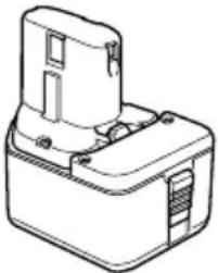
- Battery (EB1214S, EB1220BL, EB1226HL)
natural_image
Line drawing of a mechanical component with no visible text or symbols2. For WH12DAF2
There are two types of attachment sizes for the driver bit and the socket. Please refer to the table below and select the attachment size for the driver bit or socket that is appropriate for your WH12DAF2.
| Attachment size Purchase location | ||
| Type-L | 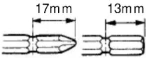 | Republic of Korea, Taiwan, Hong Kong, People's Republic of China, Republic of Singapore |
| Type-S | 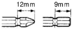 | Other than above regions. |
3. For WR12DAF2
The WR12DAF2 type is a 12.7 square driver specification. Please select the socket with the appropriate attachment size.
Optional accessories are subject to change without notice.
APPLICATION
(WH12DAF2)
○Driving and removing of small screws, small bolts, etc.
○Tightening and loosening of all types of bolts and nuts, used for securing structural items
BATTERY REMOVAL/INSTALLATION
1. Battery removal
Hold the handle tightly and push the battery latch to remove the battery. (See Fig. 1 and 2)
CAUTION:
Never short-circuit the battery.
2. Battery installation
Insert the battery while observing its polarities. (See Fig. 2)
CHARGING
Before using the power tool, charge the battery as follows.
1. Connect the charger's power cord to a receptacle
When the power cord is connected, the charger's pilot lamp will blink in red. (At 1-second intervals.)
2. Insert the battery into the charger
Insert the battery firmly, in the direction shown in Fig. 3, until it contacts the bottom of the charger compartment.
CAUTION:
○If the battery is inserted in the reverse direction, not only recharging will become impossible, but it may also cause problems in the charger such as deformed recharging terminal.
3. Charging
When inserting a battery in the charger, charging will commence and the pilot lamp will light up continuously in red.
When the battery becomes fully recharged, the pilot lamp will blink in red. (At 1-second intervals.) (See Table 1)
(1) Pilot lamp indication
The indications of the pilot lamp will be as shown in Table 1, according to the condition of the charger or the rechargeable battery.
Table 1
| Indications of the lamps | |||
| Before charging | Blinks (RED) | Lights for 0.5 seconds. Does not light for 0.5 seconds. (off for 0.5 seconds) | |
| While charging | Lights (RED) | Lights continuously | |
| Charging complete | Blinks (RED) | Lights for 0.5 seconds. Does not light for 0.5 seconds. (off for 0.5 seconds) | |
| Charging impossible | Flikers (RED) | Lights for 0.1 seconds. Does not light for 0.1 seconds. (off for 0.1 seconds) | Malfunction in the battery or the charger. |
| Charging impossible | Lights (GREEN) | Lights continuously | The battery temperature is high, making recharging impossible. |
(2) Regarding the temperatures of the rechargeable battery The temperatures for rechargeable batteries are as shown in the table below, and batteries that have become hot should be cooled for a while before being recharged.
Table 2 Recharging ranges of batteries
| Rechargeable batteries which | Temperatures at the battery can be recharged |
| EB1214S, EB1220BL | -5°C - 60°C |
| EB1226HL | 0°C - 45°C |
4. Disconnect the charger's power cord from the receptacle 5. Hold the charger firmly and pull out the battery NOTE:
Be sure to pull out the battery from the charger after use, and then keep it.
Regarding electric discharge in case of new batteries, etc.
As the internal chemical substance of new batteries and batteries that have not been used for an extended period is not activated, the electric discharge might be low when using them the first and second time. This is a temporary phenomenon, and normal time required for recharging will be restored by recharging the batteries 2 – 3 times.
How to make the batteries perform longer
(1) Recharge the batteries before they become completely exhausted. When you feel that the power of the tool becomes weaker, stop using the tool and recharge its battery. If you continue to use the tool and exhaust the electric current, the battery may be damaged and its life will become shorter.
(2) Avoid recharging at high temperatures. A rechargeable battery will be hot immediately after use. If such a battery is recharged immediately after use, its internal chemical substance will deteriorate, and the battery life will be shortened. Leave the battery and recharge it after it has cooled for a while.
CAUTION:
○If the battery is charged while it is heated because it has been left for a long time in a location subject to direct sunlight or because the battery has just been used, the pilot lamp of the charger lights up green. In such a case, first let the battery cool, then start charging.
When the pilot lamp flikers in red quickly (at 0.2-second intervals), check for and take out any foreign objects in the charger's battery installation hole. If there are no foreign objects, it is probable that the battery or charger is malfunctioning. Take it to your Authorized Service Center.
○Since the built-in micro computer takes about 3 seconds to confirm that the battery being charged with UC14YFA is taken out, wait for a minimum of 3 seconds before reinserting it to continue charging. If the battery is reinserted within 3 seconds, the battery may not be properly charged.
Before using the power tool, charge the battery as follows.
-
Connect the charger power cord to the receptacle Connecting the power cord will turn on the charger.
-
Insert the battery into the charger Insert the battery firmly while observing its direction, until it contacts the bottom of the charger (the pilot lamp lights up) (See Fig. 4).
CAUTION
If the pilot lamp does not light up, pull out the power cord from the receptacle and check the battery mounting condition.
○Regarding the temperatures of the rechargeable battery The temperatures for rechargeable batteries are as shown in Table 3.
Table 3 Recharging ranges of batteries
| Rechargeable batteries w | Temperatures at which the battery can be recharged |
| EB1214S, EB1220BL | 0°C - 45°C |
○The pilot lamp goes off to indicate that the battery is fully charged.
The battery charging time becomes longer when a temperature is low or the voltage of the power source is too low.
When the pilot lamp does not go off even if more than 120 minutes have elapsed after starting of the charging, stop the charging and contact your HITACHI AUTHORIZED SERVICE CENTER.
CAUTION
If the battery is heated due to direct sunlight, etc., just after operation, the charger pilot lamp may not light up. At that time, cool the battery first, then start charging.
-
Disconnect the charger's power cord from the receptacle
-
Hold the charger firmly and pull out the battery NOTE
After charging, pull out batteries from the charger first, and then keep the batteries properly.
Regarding electric discharge in case of new batteries, etc.
As the internal chemical substance of new batteries and batteries that have not been used for an extended period is not activated, the electric discharge might be low when using them the first and second time. This is a temporary phenomenon, and normal time required for recharging will be restored by recharging the batteries 2 – 3 times.
How to make the batteries perform longer.
(1) Recharge the batteries before they become completely exhausted.
When you feel that the power of the tool becomes weaker, stop using the tool and recharge its battery. If you continue to use the tool and exhaust the electric current, the battery may be damaged and its life will become shorter.
(2) Avoid recharging at high temperatures.
A rechargeable battery will be hot immediately after use. If such a battery is recharged immediately after use, its internal chemical substance will deteriorate, and the battery life will be shortened. Leave the battery and recharge it after it has cooled for a while.
PRIOR TO OPERATION
- Preparing and checking the work environment
Make sure that the work site meets all the conditions laid forth in the precautions.
- Checking the battery
Make sure that the battery is installed firmly. If it is at all loose it could come off and cause an accident.
- Installing the bit (WH12DAF2)
Always follow the following procedure to install driver bit. (Fig. 5)
(1) Pull the guide sleeve away from front of the tool.
(2) Insert the bit into the hexagonal hole in the anvil.
(3) Release the guide sleeve and it returns to its original position.
CAUTION:
If the guide sleeve does not return to its original position, then the bit is not installed properly.
- Selecting the socket matched to the bolt (WR12DAF2)
Be sure to use a socket which is matched to the bolt to be tightened. Using an improper socket will not only result in insufficient tightening but also in damage to the socket or nut.
A worn or deformed hex. or square-holed socket will not give an adequate tightness for fitting to the nut or anvil, consequently resulting in loss of tightening torque.
Pay attention to wear of socket hole, and replace before further wear has developed.
Finally, install the socket prescribed in Item 5. The section on “Optional Accessories” details the relationship between bolt sizes and sockets. Sockets are named according to the dihedral width of the hexagonal hole.
- Installing a socket (WR12DAF2)
Select the socket to be used.
● Pin, O-ring type (Fig. 6 and 7)
(1) Align the hole in the socket with the hole in the anvil and insert the anvil into the socket.
(2) Insert the pin into the socket.
(3) Attach the ring to the groove on the socket.
●Plunger type (Fig. 8)
Align the plunger located in the square part of the anvil with the hole in the hex. socket. Then push the plunger, and mount the hex. socket on the anvil. Check that the plunger is fully engaged in the hole. When removing the socket, reverse the sequence.
HOW TO USE
CAUTION:
○When using the light equipped hook, pay sufficient attention so that the main equipment does not fall. If the tool falls, there is a risk of accident.
○Do not attach the tip tool except phillips bit to the tool main unit when carrying the tool main unit with the light equipped hook suspended from a waist belt.
Injury may result if you carry the equipment suspended from the waist belt with sharp tipped components such as drill bit attached.
- Using the light equipped hook
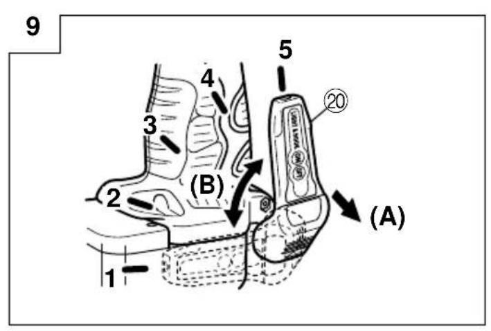
The light equipped hook can be installed on the right or left side and the angle can be adjusted in 5 steps between 0° and 80°.
(1) Operating the hook
(a) Pull out the hook toward you in the direction of arrow (A) and turn in the direction of arrow (B). (Fig. 9)
(b) The angle can be adjusted in 5 steps ( 0^ , 20^ , 40^ , 60^ , 80^ ).
Adjust the angle of the hook to the desired position for use.
(2) Switching the hook position
CAUTION:
Incomplete installation of the hook may result in bodily injury when used.
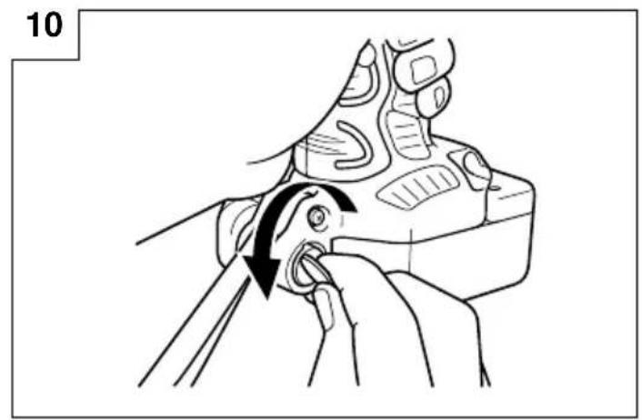
(a) Securely hold the main unit and remove the screw using a slotted head screwdriver or a coin. (Fig. 10)
(b) Remove the hook and spring. (Fig. 11)
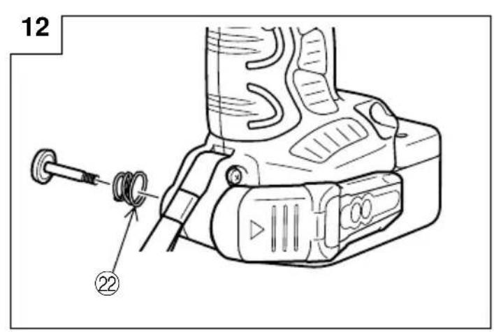
(c) Install the hook and spring on the other side and securely fasten with screw. (Fig. 12)
NOTE:
Pay attention to the spring orientation. Install the spring with larger diameter away from you. (Fig. 12)
(3) Using as an auxiliary light
(a) Press the switch to turn off the light. If forgotten, the light will turn off automatically after 15 minutes.
(b) The direction of the light can be adjusted within the range of hook positions 1 - 5. (Fig. 13)
○Lighting time
AAAA manganese batteries: approx. 15 hrs.
AAAA alkali batteries: approx. 30 hrs.
CAUTION:
Do not look directly into the light.
Such actions could result in eye injury.
(4) Replacing the batteries
(a) Loosen the hook screw with a phillips-head screwdriver (No. 1). (Fig. 14)
Remove the hook cover by pushing in the direction of the arrow. (Fig. 15)
(b) Remove the old batteries and insert the new batteries. Align with the hook indications and position the plus (+) and minus (−) terminals correctly. (Fig. 16)
(c) Align the indentation in the hook main body with the protuberance of the hook cover, press the hook cover in the direction opposite to that of the arrow shown in Fig. 15 and then tighten the screw. Use commercially available AAAA batteries (1.5 V).
NOTE:
Do not tighten the screw excessively. Such action could strip the screw threads.
CAUTION:
○Failure to observe the following can result in battery leakage, rust or malfunction.
Position the plus (+) and minus (−) terminals correctly. Replace both batteries at the same time. Do not mix old and new batteries.
Remove exhausted batteries from the hook immediately.
○Do not discard batteries together with normal trash and do not throw batteries into fire.
○Store batteries out of the reach of children.
○Use batteries correctly in accordance with the battery specifications and indications.
2. Check the rotational direction
The bit rotates clockwise (viewed from the rear side) by pushing the R-side of the push button.
The L-side of the push button is pushed to turn the bit counterclockwise. (See Fig. 17) (The L) and (R) marks are provided on the body.)
CAUTION:
The push button cannot be switched while the impact driver is turning. To switch the push button, stop the impact driver, then set the push button.
3. Switch operation
○When the trigger switch is depressed, the tool rotates. When the trigger is released, the tool stops.
☐The rotational speed can be controlled by varying the amount that the trigger switch is pulled. Speed is low when the trigger switch is pulled slightly and increases as the trigger switch is pulled more.
4. Tightening and loosening screws (WH12DAF2)
Install the bit that matches the screw, line up the bit in the grooves of the head of the screw, then tighten it.
Push the impact driver just enough to keep the bit fitting the head of the screw.
CAUTION:
Applying the impact driver for too long tightens the screw too much and can break it.
Tightening a screw with the impact driver at an angle to that screw can damage the head of the screw and the proper force will not be transmitted to the screw. Tighten with this impact driver lined up straight with the screw.
5. Number of screws tightenings possible (WH12DAF2)
Please refer to the table below for the number of screw tightened possible with one charge.
EB1214S
| Screw used No. of tightenings | |
| Wood screw ø4 · 50 (Soft wood) | Approx. 190 |
| Machine screw M8 · 16 | Approx. 500 |
These values may vary slightly, according to surrounding temperature and battery characteristics.
6. Number of bolt tightened possible (WR12DAF2)
Please refer to the table below for the number of bolt tightened possible with one charge.
EB1214S
| Bolt used No. of tightenings | |
| M12 · 45 High tension bolt | Approx. 87 |
These values may vary slightly, according to surrounding temperature and battery characteristics.
NOTE:
The use of the battery EB1226HL in a cold condition (below 0 degree Centigrade) can sometimes result in the weakened tightening torque and reduced amount of work. This, however, is a temporary phenomenon, and returns to normal when the battery warms up.
OPERATIONAL CAUTIONS
1. Resting the unit after continuous work
After use for continuous bolt-tightening work, rest the unit for 15 minutes or so when replacing the battery. The temperature of the motor, switch, etc., will rise if the work is started again immediately after battery replacement, eventually resulting in burnout.
NOTE:
Do not touch the hammer case, as it gets very hot during continuous work.
2. Cautions on use of the speed control switch
This switch has a built-in, electronic circuit which steplessly varies the rotation speed. Consequently, when the switch trigger is pulled only slightly (low speed rotation) and the motor is stopped while continuously driving in screws, the components of the electronic circuit parts may overheat and be damaged.
3. Tightening torque
Refer to Fig. 18 and Fig. 19 for the tightening torque of bolts (according to size), under the conditions shown in Fig. 20. Please use this example as a general reference, as tightening torque will vary according to tightening conditions.
NOTE:
○If a long striking time is used, screws will be strongly tightened. This may cause the screw to break, or may damage the tip of the bit.
○If the unit is held at an angle to the screw being tightened, the head of the screw may be damaged, or the specified torque may not be transmitted to the screw. Always keep the unit and the screw being tightened in a straight line.
4. Use a tightening time suitable for the screw
The appropriate torque for a screw differs according to the material and size of the screw, and the material being screwed etc., so please use a tightening time suitable for the screw. In particular, if a long tightening time is used in the case of screws smaller than M8, there is a danger of the screw breaking, so please confirm the tightening time and the tightening torque beforehand.
5. Work at a tightening torque suitable for the bolt under impact
The optimum tightening torque for nuts or bolts differs with material and size of the nuts or bolts. An excessively large tightening torque for a small bolt may stretch or break the bolt. The tightening torque increases in proportion to the operation time. Use the correct operating time for the bolt.
6. Holding the tool
Hold the impact wrench firmly with both hands. In this case hold the wrench in line with the bolt. It is not necessary to push the wrench very hard. Hold the wrench with a force just sufficient to counteract the impact force.
7. Confirm the tightening torque
The following factors contribute to a reduction of the tightening torque. So confirm the actual tightening torque needed by screwing up some bolts before the job with a hand torque wrench. Factors affecting the tightening torque are as follows.
(1) Voltage
When the discharge margin is reached, voltage decreases and tightening torque is lowered.
(2) Operating time
The tightening torque increases when the operating time increases. But the tightening torque does not increase above a certain value even if the tool is driven for a long time. (See Fig. 18 and 19)
(3) Diameter of bolt
The tightening torque differs with the diameter of the bolt as shown in Fig. 18 and 19. Generally a larger diameter bolt requires larger tightening torque.
(4) Tightening conditions
The tightening torque differs according to the torque ratio; class, and length of bolts even when bolts with the same size threads are used. The tightening torque also differs according to the condition of the surface of workpiece through which the bolts are to be tightened. When the bolt and nut turn together, torque is greatly reduced.
(5) Using optional parts (WR12DAF2)
The tightening torque is reduced a little when an extension bar, universal joint or a long socket is used.
(6) Clearance of the socket (WR12DAF2)
A worn or deformed hex. or a square-holed socket will not give an adequate tightness to the fitting between the nut or anvil, consequently resulting in loss of tightening torque.
Using an improper socket which does not match to the bolt will result in an insufficient tightening torque.
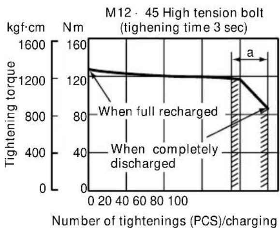
(7) Tightening torque varies, depending on the battery's charge level. (WR12DAF2)
Fig. 21 show examples of the relationship between tightening torque and the number of tightenings, for WR12DAF2. As shown, tightening torque gradually weakens with the increase in the number of tightenings. In particular, as the torque decreases very close to the complete discharge ("a" margin in graph), the unit's impact weakens, the number of time impacts declines and tightening torque drops off abruptly. If this occurs, check torque level, then recharge the battery if necessary.
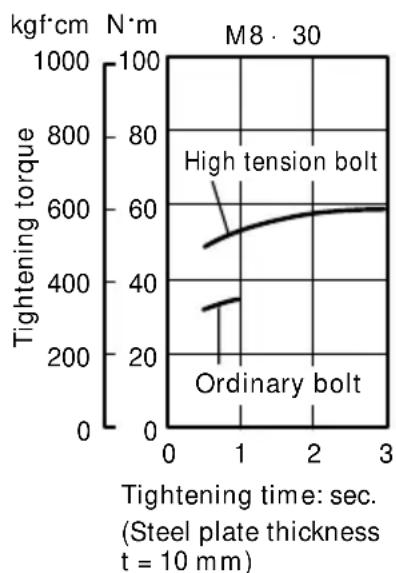
line
| Tightening time: sec. (Steel plate thickness t = 10 mm) | Tightening torque (kgf·cm) | | -------------------------------------------------------- | -------------------------- | | 0 | 50 | | 1 | 60 | | 2 | 65 | | 3 | 70 |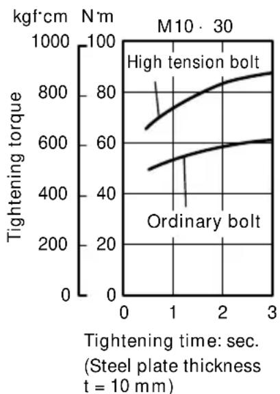
line
| Tightening time: sec. (Steel plate thickness t = 10 mm) | Tightening torque (kgf·cm) - High tension bolt | Tightening torque (kgf·cm) - Ordinary bolt | | -------------------------------------------------------- | ----------------------------------------------- | -------------------------------------------- | | 0 | 650 | 500 | | 1 | 750 | 550 | | 2 | 850 | 600 | | 3 | 900 | 620 |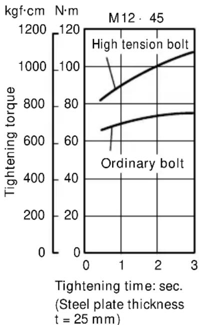
line
| Tightening time (sec.) | Tightening torque (kgf·cm) - High tension bolt | Tightening torque (kgf·cm) - Ordinary bolt | | ---------------------- | ----------------------------------------------- | ------------------------------------------- | | 0 | 80 | 650 | | 1 | 90 | 700 | | 2 | 100 | 750 | | 3 | 110 | 780 |Fig. 18
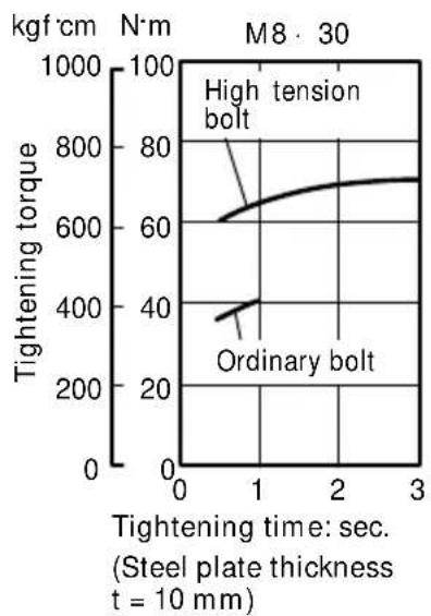
line
| Tightening time: sec. | Tightening torque (kgf·cm) | | --------------------- | -------------------------- | | 0 | 600 | | 1 | 700 | | 2 | 750 | | 3 | 750 |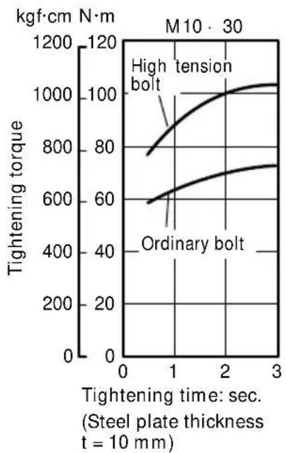
line
| Tightening time: sec. | High tension bolt (kgf·cm N·m) | Ordinary bolt (kgf·cm N·m) | | --------------------- | ------------------------------- | -------------------------- | | 0 | 800 | 600 | | 1 | 1000 | 650 | | 2 | 1050 | 700 | | 3 | 1050 | 750 |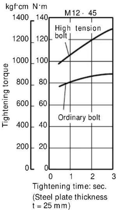
line
| Tightening time: sec. | Tightening torque (kgf·cm) - High tension | Tightening torque (kgf·cm) - Ordinary bolt | | --------------------- | ------------------------------------------ | ------------------------------------------- | | 0 | 950 | 750 | | 1 | 1050 | 800 | | 2 | 1200 | 850 | | 3 | 1300 | 875 |Fig. 19
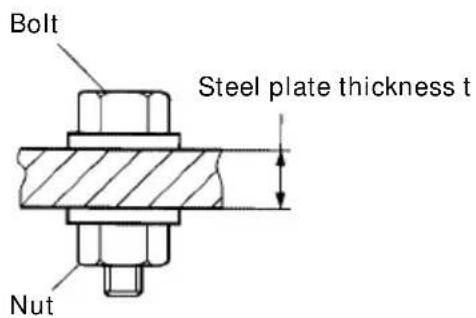
* The following bolt is used. Ordinary bolt: Strength grade 4.8 High tension bolt: Strength grade 12.9
(Explanation of strength grade: 4 — Yield point of bolt: 32 kgf/mm ^2 8 — Pulling strength of bolt: 40 kgf/mm ^2 )
Fig. 20
(WR12DAF2)
line
| Number of tightenings (PCS)/charging | Tightening torque (kgf·cm) | | ------------------------------------ | -------------------------- | | 0 | 1200 | | 20 | 1200 | | 40 | 1200 | | 60 | 1200 | | 80 | 1200 | | 100 | 1200 | | 120 | 1200 | | 140 | 1200 | | 160 | 1200 | | 180 | 1200 | | 200 | 800 | | 220 | 800 | | 240 | 800 | | 260 | 800 | | 280 | 800 | | 300 | 800 | | 320 | 800 | | 340 | 800 | | 360 | 800 | | 380 | 800 | | 400 | 800 | | 420 | 800 | | 440 | 800 | | 460 | 800 | | 480 | 800 | | 500 | 800 | | 520 | 800 | | 540 | 800 | | 560 | 800 | | 580 | 800 | | 600 | 800 | | 620 | 800 | | 640 | 800 | | 660 | 800 | | 680 | 800 | | 700 | 800 | | 720 | 800 | | 740 | 800 | | 760 | 800 | | 780 | 800 | | 800 | 800 | | 820 | 800 | | 840 | 800 | | 860 | 800 | | 880 | 800 | | 900 | 800 | | 920 | 800 | | 940 | 800 | | 960 | 800 | | 980 | 800 | | 1000 | 800 |Fig. 21
MAINTENANCE AND INSPECTION
1. Inspecting the driver bit (WH12DAF2)
Using a broken bit or one with a worn out tip is dangerous because the bit can slip. Replace it.
2. Inspecting the socket (WR12DAF2)
A worn or deformed hex. or a square-holed socket will not give an adequate tightness to the fitting between the nut or anvil, consequently resulting in loss of tightening torque. Pay attention to wear of a socket holes periodically, and replace with a new one if needed.
3. Inspecting the mounting screws
Regularly inspect all mounting screws and ensure that they are properly tightened. Should any of the screws be loose, retighten them immediately. Failure to do so may result in serious hazard.
4. Cleaning of the outside
When the impact driver is stained, wipe with a soft dry cloth or a cloth moistened with soapy water. Do not use chloric solvents, gasoline or paint thinner, as they melt plastics.
5. Storage
Store the impact driver in a place in which the temperature is less than 40^ C, and out of reach of children.
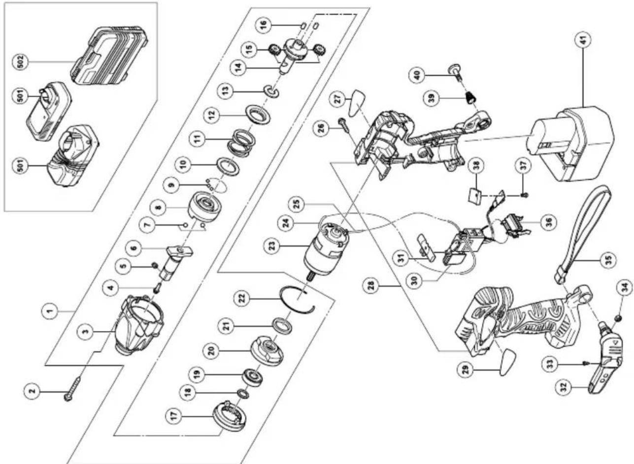
6. Service parts list
A : Item No.
B : Code No.
C: No. Used
D : Remarks
CAUTION:
Repair, modification and inspection of Hitachi Power Tools must be carried out by an Hitachi Authorized Service Center.
This Parts List will be helpful if presented with the tool to the Hitachi Authorized Service Center when requesting repair or other maintenance.
In the operation and maintenance of power tools, the safety regulations and standards prescribed in each country must be observed.
MODIFICATIONS:
Hitachi Power Tools are constantly being improved and modified to incorporate the latest technological advancements.
Accordingly, some parts (i.e. code numbers and/or design) may be changed without prior notice.
NOTE:
Due to HITACHI's continuing program of research and development, the specifications herein are subject to change without prior notice.
Information concerning airborne noise and vibration
The measured values were determined according to EN50260.
The typical A-weighted sound pressure level: 95 dB
The typical A-weighted sound power level: 108 dB
Wear ear protection.
The typical weighted root mean square acceleration
value: 9.6 m/s² (WH12DAF2)
7.6 m/s² (WR12DAF2)
natural_image
Line drawing of a mechanical component with no visible text or symbols2. Für WH12DAF2
natural_image
Line drawing of a mechanical component with no visible text or symbols2. Για το WH12DAF2
natural_image
Technical line drawing of a mechanical component with no visible text or symbols2. Model WH12DAF2
natural_image
Technical line drawing of a mechanical component with mounting holes and internal slots (no text or symbols)2. WH12DAF2 esetén
- Charger (UC14YFA or UC18YG).... 1
- Plastic case .... 1
Standard accessories are subject to change without notice.
natural_image
Line drawing of a mechanical component with no visible text or symbols2. Pro WH12DAF2
natural_image
Line drawing of a mechanical component with no visible text or symbols- WH12DAF2 için
natural_image
Technical line drawing of a mechanical component with no visible text or symbols- Для модели WH12DAF2
WR12DAF2
| A | B | C | D | A | B | C | D |
| 1 | 324-856 | 1 | "3-22" | 39 | 319-926 | 1 | |
| 2 | 992-630 | 4 | D4 · 40 | 40 | 319-927 | 1 | M5 |
| 3 | 324-857 | 1 | 41-1 | ———1 | EB1214S | ||
| 4 | 323-194 | 1 | 41-2 | ———1 | EB1220BL | ||
| 5 | 323-193 | 1 | 41-3 | ———1 | EB1226HL | ||
| 6 | 323-192 | 1 | 501-1 | ———1 | UC18YG | ||
| 7 | 959-154 | 2 | D5.556 | 501-2 | ———1 | UC14YFA | |
| 8 | 323-949 | 1 | 502-1 | 324-359 | 1 | ||
| 9 | 321-934 | 28 | D3 | 502-2 | 322-611 | 1 | "GBR" |
| 10 | 315-978 | 1 | |||||
| 11 | 323-944 | 1 | |||||
| 12 | 316-172 | 1 | |||||
| 13 | 316-171 | 1 | |||||
| 14 | 323-945 | 1 | |||||
| 15 | 323-941 | 2 | |||||
| 16 | 323-942 | 2 | |||||
| 17 | 323-946 | 1 | |||||
| 18 | 319-911 | 1 | |||||
| 19 | 690-1VV | 1 | 6901VVCMPS2L | ||||
| 20 | 323-947 | 1 | |||||
| 21 | 321-894 | 1 | |||||
| 22 | 321-893 | 1 | |||||
| 23 | 323-948 | 1 | |||||
| 24 | 321-876 | 1 | 115L | ||||
| 25 | 321-877 | 1 | 60L | ||||
| 26 | 302-086 | 7 | D4 · 20 | ||||
| 27 | ———1 | ||||||
| 28 | 324-855 | 1 | |||||
| 30 | 321-917 | 1 | |||||
| 31 | 321-871 | 1 | |||||
| 29 | ———1 | ||||||
| 32 | 321-918 | 1 | " 33, 34" | ||||
| 33 | 321-672 | 2 | D2 · 6 | ||||
| 34 | 320-288 | 1 | M5 | ||||
| 35 | 306-952 | 1 | |||||
| 36 | 323-710 | 1 | |||||
| 37 | 320-777 | 1 | |||||
| 38 | 320-776 | 1 | |||||
| English | Magyar | ||
| GUARANTEE CERTIFICATE1Model No.2Serial No.3Date of Purchase4Customer Name and Address5Dealer Name and Address(Please stamp dealer name and address) | GARANCIA BIZONYLAT1Típusszám2Sorozatszám3A vásárlás dátuma4 A Vásárló neve és címe5 A Kereskedő neve és címe(Kérjük ide elhelyezni a Kereskedő nevének és címének pecsétjét) | ||
| Deutsch | GARANTIESCHEIN1Modell-Nr.2Serien-Nr.3Kaufdaturn4Name und Anschrift des Kunden5Name und Anschrift des Händlers(Bitte mit Namen und Anschrift des Handlers abstempeln) | Čeština | ZÁRUČNÍ LIST1Model č.2Série č.3Datum nákupu4 Jméno a adresa zákazníka5 Jméno a adresa prodejce(Prosíme o razítko se jménem a adresou prodejce) |
| Ελληνικά | Türkçe | ||
| ΠΙΣΤΟΠΟΙΗΤΙΚΟ ΕΓΓΥΗΣΗΣ1Αρ. Μοντέλου2Αύξων Αρ.3Ημερομηνία αγοράς4 ́Ονομα και διεύθυνση πελάτη5 ́Ονομα και διεύθυνση μεταπωλητή(Παρακαλούμε να χρησιμοποιηθεί σφραγίδα) | GARANTI SERTIĆIKASI1Model No.2Seri No.3Satın Alma Tarihi4Müşteri Adı ve Adresi5Bayi Adı ve Adresi(Lütfen bayi adını ve adresini kaşe olarak basın) | ||
| Polski Русский | |||
| GWARANCJA1Model2Numer seryjny3Data zakupu4Nazwa klienta i adres5Nazwa dealera i adres(Pieczęć punktu sprzedaży) | ГАРАНТИЙНЫЙ СЕРТИФИКАТ1Модель No2Серийный No3Дата покупки4 Название и адрес заказчика5 Название и адрес дилера(Пожалуйста, внесите название и адрес дилера) | ||
HITACHI
| 1 | |
| 2 | |
| 3 | |
| 4 | |
| 5 |
natural_image
Simple line drawing of a quill pen in an inkwell (no text or symbols)
natural_image
Line drawing of a quill pen in an inkwell (no text or symbols)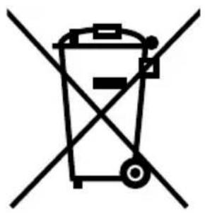
natural_image
Symbol of a trash bin crossed out by two diagonal lines (no text or numbers present)English
Only for EU countries
Do not dispose of electric tools together with household waste material!
In observance of European Directive 2002/96/EC on waste electrical and electronic equipment and its implementation in accordance with national law, electric tools that have reached the end of their life must be collected separately and returned to an environmentally compatible recycling facility.
Deutsch
Nur für EU-Länder
- Cordless Impact Driver/Wrench
- GENERAL OPERATIONAL PRECAUTIONS
- PRECAUTIONS FOR CORDLESS IMPACT DRIVER
- PRECAUTIONS FOR CORDLESS IMPACT WRENCH
- SPECIFICATIONS
- MODEL
- STANDARD ACCESSORIES
- OPTIONAL ACCESSORIES (Sold separately)
- For WH12DAF2
- For WR12DAF2
- APPLICATION
- BATTERY REMOVAL/INSTALLATION
- Battery removal
- CAUTION:
- Battery installation
- CHARGING
- Connect the charger's power cord to a receptacle
- Insert the battery into the charger
- Charging
- Disconnect the charger's power cord from the receptacle 5. Hold the charger firmly and pull out the battery NOTE:
- Regarding electric discharge in case of new batteries, etc.
- How to make the batteries perform longer
- CAUTION
- How to make the batteries perform longer.
- PRIOR TO OPERATION
- HOW TO USE
- NOTE:
- Check the rotational direction
- Switch operation
- Tightening and loosening screws (WH12DAF2)
- Number of screws tightenings possible (WH12DAF2)
- Number of bolt tightened possible (WR12DAF2)
- OPERATIONAL CAUTIONS
- Resting the unit after continuous work
- Cautions on use of the speed control switch
- Tightening torque
- Use a tightening time suitable for the screw
- Work at a tightening torque suitable for the bolt under impact
- Holding the tool
- Confirm the tightening torque
- Voltage
- (WR12DAF2)
- MAINTENANCE AND INSPECTION
- Inspecting the driver bit (WH12DAF2)
- Inspecting the socket (WR12DAF2)
- Inspecting the mounting screws
- Cleaning of the outside
- Storage
- Service parts list
- MODIFICATIONS:
- Information concerning airborne noise and vibration
- Für WH12DAF2
- Για το WH12DAF2
- Model WH12DAF2
- WH12DAF2 esetén
- Pro WH12DAF2
- English
- Deutsch
Brand : HITACHI
Model : WR12DAF2
Category : Tower