
DV20VB2KS - Hammer drill HITACHI - Free user manual and instructions
Find the device manual for free DV20VB2KS HITACHI in PDF.

| Product type | Corded hammer drill |
| Brand | HITACHI |
| Model | DV20VB2KS |
| Power consumption | 790 W |
| Supply voltage | 110-240 V~, 50/60 Hz |
| No-load speed (low/high) | 0-1000 / 0-3000 rpm |
| Hammering speed (low/high) | 8,000 / 26,000 bpm |
| Drilling capacity - Steel | 13 mm (low speed) / 8 mm (high speed) |
| Drilling capacity - Concrete | 20 mm (low speed) / 13 mm (high speed) |
| Drilling capacity - Wood | 40 mm (low speed) / 25 mm (high speed) |
| Weight (without cord) | 2.2 kg |
| Chuck type | Keyed or keyless chuck depending on version |
| Main functions | Drilling only, hammer + rotation, reversible rotation, electronic variable speed |
| Safety | Safety stop, trigger lock, adjustable side handle, depth gauge |
| Maintenance and cleaning | Inspection and replacement of brushes by authorized service center; cord replacement by authorized service center; regularly clean ventilation slots |
| Spare parts and repairability | Repairs exclusively by an authorized HITACHI service center; use original parts |
| General information | Compliant with EN60745 standard; sound pressure level 99 dB(A); sound power level 110 dB(A); vibration 10 m/s² |
Frequently Asked Questions - DV20VB2KS HITACHI
User questions about DV20VB2KS HITACHI
0 question about this device. Answer the ones you know or ask your own.
Ask a new question about this device
Download the instructions for your Hammer drill in PDF format for free! Find your manual DV20VB2KS - HITACHI and take your electronic device back in hand. On this page are published all the documents necessary for the use of your device. DV20VB2KS by HITACHI.
USER MANUAL DV20VB2KS HITACHI
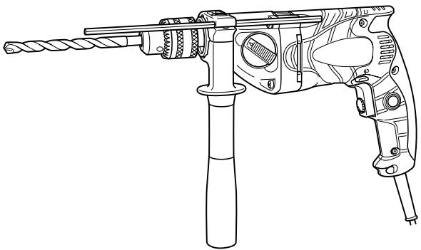
Impact Drill
Schlagbohrmaschine
Perceuse percussion
Trapano a percussione
Klop-boormachine
Taladro de percuspion
Berbequim com percussione
Kpouotiko δραπavo
DV 20VB2
Read through carefully and understand these instructions before use.
These Anleitung vor Benutzung des Werkzeugs sorgfaltig durchlesen und verstehen.
Lire soigneusement et bien assimiler ces instructions avant usage.
Prima dell'uso leggere attentamente e comprehende queste istruzioni.
Deze gebruiksaanwijzing s.v.p. voor gebruik zorgvuldig doorlezen.
Leer cuidadosamente y comprehender estas instrueriones antes del uso.
Antes de usur, leia com cuidado para assimilar estas instruções.
AiaβaTe npoaeKtika kai katavnoTe autcTc Tc obnyic npiv tn xPnO.

Handling instructions Bedienungsanleitung Mode d'emploi Istruzioni per l'uso Gebruiksaanwijzing Instrucciones de manejo Instruções de uso Oδηγες xειρισού
1
2
3
4
5
6
7
8
9
10
11
| English | Deutsch | François | Italiano | |
| ① | Drill chuck | Bohrfutter | Mandrin | Mandrino trapano |
| ② | Chuck wrench | Futterschlüssel | Clé de serrage | Chiave mandrino |
| ③ | Tighten | Anziehen | Serrer | Stringere |
| ④ | Loosen | Lösen | Desserer | Allentare |
| ⑤ | Sleeve | Manschette | Manchon | Collare |
| ⑥ | Ring | Ring | Anneau | Anello |
| ⑦ | Lock collar | Verriegelungsband | Collier de verrouillage | Collare di blocco |
| ⑧ | Side handle | Seitengriff | Poiignée latérale | Maniglia laterale |
| ⑨ | Switch trigger | Abzugschalter | Gâchette | Grilletto interruptore |
| ⑩ | Push button | Druckknopf | Bouton pousoir | Pulsante |
| ⑪ | (R) mark | Markierung (R) | Repère (R) | Segno (R) |
| ⑫ | (L) mark | Markierung (L) | Repère (L) | Segno (L) |
| ⑬ | Depth gauge | Tiefenlehre | Jauge de profondeur | Calibro di profondità |
| ⑭ | Change lever | Umschalthebel | Levier de changement | Leva di cambiamento |
| ⑮ | Impact | Schlagbohre | Percussion | Impatto |
| ⑯ | Rotation | Bohren | Rotation | Rotazione |
| ⑰ | Gear shift dial | Gangschaltscheibe | Bouton de changement de vitesse | Regolazione di velocità |
| ⑱ | Speed control dial | Drehzahlskala | Molette de commande de la vitesse | Comando di velocità |
| ⑲ | High speed | Hohe Drehzahl | Vitesse elevée | Alta velocità |
| ⑳ | Low speed | Niedrige Drehzahl | Petite vitesse | Bassa velocità |
| ⑴ | Stopper | Stopper | Butée | Fermo |
| Nederland | Espanol | Portuguès | Eλληνικά | |
| ① | Boorkop | Portabrocas | Mandril | Σφικτήρας δραπάνου |
| ② | Boorkopsstreutel | Llave | Chave do mandril | Κλείδι σφικτήρα |
| ③ | Aandraaien | Apretar | Apertar | Σφιξτέ |
| ④ | Losdraaien | Aflojar | Afrouxar | Χαλαρώστέ |
| ⑤ | Klembus | Manguito | Manguito | Συνδετικός δακτύλιος |
| ⑥ | Ring | Anillo | Anel | Δακτύλιος |
| ⑦ | Vergrendelkraag | Collar de bloqueo | Colar de bloqueio | Κολάρο ααφαλείας |
| ⑧ | Zijhendel | Asa lateral | Empunhadura lateral | Πλεύρική λαβή |
| ⑨ | Trekkerschakelaar | Interruptor de gatillo | Interruptor de gatilho | Σκανδάλη διακόπτης |
| ⑩ | Drukknop | Botón pulsador | Botão-interruption | Κουμπι ωθησης |
| ⑪ | (R) merkteken | Marca (R) | Marca (R) | (R) σημάδι |
| ⑫ | (L) merkteken | Marca (L) | Marca (L) | (L) σημάδι |
| ⑬ | Diepteter | Calibrador de profundidad | Sonda | Μετρητής βάθους |
| ⑭ | Wisselhendel | Palanca de cambio | Seletor | Μοχλός αλλayής |
| ⑮ | Slagboor | Impacto | Impacto | Κρούση |
| ⑯ | Rotatie | Rotación | Rotação | Περιστροφή |
| ⑰ | Toerentalkiezer | Dial de cambio | Botão de engrenagem | Καντράν αλλayής ταχύτητας |
| ⑱ | Toerentalregeling | Dial de control de velocidad | Dial de controle de velocidade | Καντράν ελέγχου ταχύτητας |
| ⑲ | Hoog toerental | Alta velocidad | rotação | Υψηλή ταχύτητα |
| ⑳ | Laag toerental | Baja velocidad | Baixa rotação | Χαμηλή ταχύτητα |
| ⑴ | Stopper | Tope | Obturator | Στόπερ |
GENERAL OPERATIONAL PRECAUTIONS
WARNING! When using electric tools, basic safety precautions should always be followed to reduce the risk of fire, electric shock and personal injury, including the following.
Read all these instructions before operating this product and save these instructions.
For safe operations:
- Keep work area clean. Cluttered areas and benches invite injuries.
- Consider work area environment. Do not expose power tools to rain. Do not use power tools in damp or wet locations. Keep work area well lit.
Do not use power tools where there is risk to cause fire or explosion.
3. Guard against electric shock. Avoid body contact with earthed or grounded surfaces. (e.g. pipes, radiators, ranges, refrigerators).
4. Keep children and infirm persons away. Do not let visitors touch the tool or extension cord. All visitors should be kept away from work area.
5. Store idle tools. When not in use, tools should be stored in a dry, high or locked up place, out of reach of children and infirm persons.
6. Do not force the tool. It will do the job better and safer at the rate for which it was intended.
7. Use the right tool. Do not force small tools or attachments to do the job of a heavy duty tool. Do not use tools for purposes not intended; for example, do not use circular saw to cut tree limbs or logs.
8. Dress properly. Do not wear loose clothing or jewelry, they can be caught in moving parts. Rubber gloves and non-skid footwear are recommended when working outdoors. Wear protecting hair covering to contain long hair.
9. Use eye protection. Also use face or dust mask if the cutting operation is dusty.
10. Connect dust extraction equipment.
If devices are provided for the connection of dust extraction and collection facilities ensure these are connected and properly used.
- Do not abuse the cord. Never carry the tool by the cord or yank it to disconnect it from the receptacle. Keep the cord away from heat, oil and sharp edges.
- Secure work. Use clamps or a vise to hold the work. It is safer than using your hand and it frees both hands to operate tool.
- Do not overreach. Keep proper footing and balance at all times.
- Maintain tools with care. Keep cutting tools sharp and clean for better and safer performance. Follow instructions for lubrication and changing accessories. Inspect tool cords periodically and if damaged, have it repaired by authorized service center. Inspect extension cords periodically and replace, if damaged. Keep handles dry, clean, and free from oil and grease.
- Disconnect tools. When not in use, before servicing, and when changing accessories such as blades, bits and cutters.
-
Remove adjusting keys and wrenches. Form the habit of checking to see that keys and adjusting wrenches are removed from the tool before turning it on.
-
Avoid unintentional starting. Do not carry a plugged-in tool with a finger on the switch. Ensure switch is off when plugging in.
- Use outdoor extension leads. When tool is used outdoors, use only extension cords intended for outdoor use.
- Stay alert. Watch what you are doing. Use common sense. Do not operate tool when you are tired.
- Check damaged parts. Before further use of the tool, a guard or other part that is damaged should be carefully checked to determine that it will operate properly and perform its intended function. Check for alignment of moving parts, free running of moving parts, breakage of parts, mounting and any other conditions that may affect its operation. A guard or other part that is damaged should be properly repaired or replaced by an authorized service center unless otherwise indicated in this handling instructions. Have defective switches replaced by an authorized service center. Do not use the tool if the switch does not turn it on and off.
- Warning The use of any accessory or attachment, other than those recommended in this handling instructions, may present a risk of personal injury.
- Have your tool repaired by a qualified person. This electric tool is in accordance with the relevant safety requirements. Repairs should only be carried out by qualified persons using original spare parts. Otherwise this may result in considerable danger to the user.
PRECAUTIONS ON USING IMPACT DRILL
- Before drilling into walls, ceilings or floors, ensure that there are no concealed power cables inside.
- Always use side handle and hold the tool firmly with both hands.
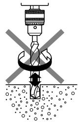
- Always use the impact drill with clockwise rotation, when using it as an impact drill. (Fig. 11)
SPECIFICATIONS
| Voltage (by areas)* | (110V, 220V, 230V, 240V) ∅ | ||
| Power input | 790 W* | ||
| Speed change | 1 | 2 | |
| No load speed | Forward rotation | 0 – 1000 min-1 | 0 – 3000 min-1 |
| Reverse rotation | 0 – 600 min-1 | 0 – 1800 min-1 | |
| Capacity | Steel | 13 mm | 8 mm |
| Concrete | 20 mm | 13 mm | |
| Wood | 40 mm | 25 mm | |
| Full load impact rate | 8000 min-1 | 26000 min-1 | |
| Weight (without cord) | 2.2 kg | ||
- Be sure to check the nameplate on product as it is subject to change by areas.
STANDARD ACCESSORIES
(1) Chuck Wrench (Spec. only for keyed chuck) 1
(2) Side Handle 1
(3) Depth Gauge 1
Standard accessories are subject to change without notice.
OPTIONAL ACCESSORIES (sold separately)
(1) Impact Drill Bit (for concrete)
3.2 mm - 20 mm dia.
Optional accessories are subject to change without notice.
APPLICATIONS
By combined actions of ROTATION and IMPACT: Boring holes in hard materials (concrete, marble, granite, tiles, etc.)
By ROTATIONAL action:
Boring holes in metal, wood and plastic.
PRIOR TO OPERATION
1. Power source
Ensure that the power source to be utilized conforms to the power requirements specified on the product nameplate.
2. Power switch
Ensure that the power switch is in the OFF position. If the plug is connected to a receptacle while the power switch is in the ON position, the power tool will start operating immediately, inviting serious accident.
3. Extension cord
When the work area is removed from the power source, use an extension cord of sufficient thickness and rated capacity. The extension cord should be kept as short as practicable.
4. Selecting the appropriate drill bit
When boring concrete or stone
Use the drill bits specified in the Optional Accessories.
When boring metal or plastic
Use an ordinary metalworking drill bit.
When boring wood
Use an ordinary woodworking drill bit.
However, when drilling 6.5mm or smaller holes, use a metalworking drill bit.
5. Mounting and dismounting of the bit.
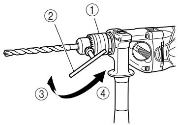
For keyed chuck (Fig. 1)
(1) Open the chuck jaws, and insert the bit into the chuck.
(2) Place the chuck wrench in each of the three holes in the chuck, and turn it in the clockwise direction (viewed from the front side). Tighten securely.
(3) To remove the bit, place the chuck wrench into one of the holes in the chuck and turn it in the counterclockwise direction.
Forkeyless chuck
The country of use will determine whether Type A or Type B keyless chuck is required.
Type A (Fig. 2)
(1) Mounting the bit
Turn the lock collar in the direction "AUF" and open the chuck. After inserting the drill bit into the chuck as far it will go, turn the lock collar in the "ZU" direction. Grip the ring and close the chuck by turning the sleeve clockwise as viewed from the front.
(2) Dismounting the bit
Turn the lock collar in the direction "AUF" to release the chucking force. Grip the ring and open the chuck by turning the sleeve counterclockwise.
NOTE
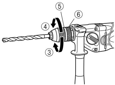
When the sleeve does not become loose any further, fix the side handle to ring, hold side handle firmly, then turn the sleeve to loosen by hand. (Fig. 4)
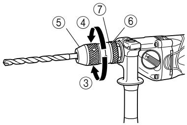
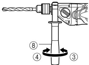
Type B (Fig. 3)
(1) Mounting the bit
Turn the sleeve counterclockwise and open the chuck. After inserting the drill bit into the chuck as far it will go, grip the ring and close the chuck by turning the sleeve clockwise as viewed from the front.
(2) Dismounting the bit
Grip the ring and open the chuck by turning the sleeve counterclockwise.
NOTE
When the sleeve does not become loose any further, fix the side handle to ring, hold side handle firmly, then turn the sleeve to loosen by hand. (Fig. 4)
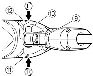
6. Check the rotational direction (Fig. 5)
The bit rotates clockwise (viewed from the rear side) by pushing the R-side of the push button.
The L-side of the push button is pushed to turn the bit counterclockwise.
(The L) and (R) marks are provided on the body.) CAUTION
Always use the impact drill with clockwise rotation, when using it as an impact drill.
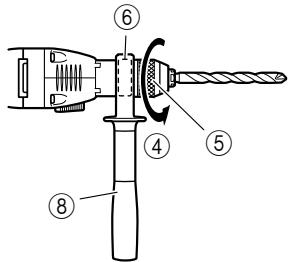
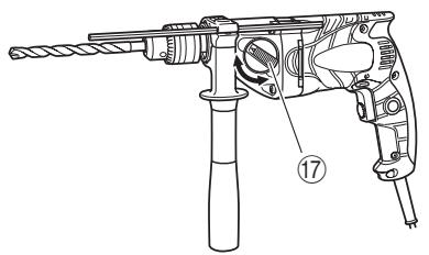
7. Fixing the side handle (Fig. 6)
Attach the side handle to the mounting part.
Rotate the side handle grip in a clockwise direction to secure it.
Set the side handle to a position that is suited to the operation and then securely tighten the side handle grip.
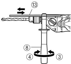
To attach a depth gauge on the side handle, insert the gauge into the U-shaped groove on the side handle, adjust the position of the depth gauge in accordance with the desired depth of the hole, and firmly tighten the side handle grip. (Fig. 7)
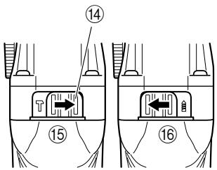
8. IMPACT to ROTATION changeover (Fig. 8)
Shift the change lever between the right and left positions to switch easily between IMPACT (rotation and impact) and ROTATION (rotation only), respectively.
To bore holes in hard materials such as concrete, stone and tiles, shift the change lever to the right-hand position (as indicated by the T mark).
The drill bit operates by the combined actions of impact and rotation.
To bore holes in metal, wood and plastic, shift the change lever to the left-hand position (as indicated by the 1 mark). The drill bit operates by rotational action only, as in the case of a conventional electric drill.
CAUTION
Do not use the Impact Drill in the IMPACT function if the material can be bored by rotation only. Such action will not only reduce drill efficiency, but may also damage the drill tip.
Operating the Impact Drill with the change lever in mid-position may result in damage. When switching, make sure that you shift the change lever to the correct position.
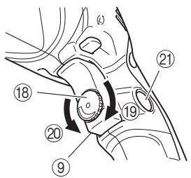
9. High-speed/Low-speed changeover:
Prior to changing speed, ensure that the switch is in the OFF position, and the drill has come to a complete stop.
To change speed, rotate the gear shift dial as indicated by the arrow in Fig. 9. The numeral "1" engraved on the drill body denotes low speed, the numeral "2" denotes high speed.
If it is hard to turn the gear shift dial, turn the chuck slightly in either direction and then turn the gear shift dial again.
HOW TO USE
1. Switch operation
- When the trigger is depressed, the tool rotates. When the trigger is released, the tool stops.
The rotational speed of the drill can be controlled by varying the amount that the trigger switch is pulled. Speed is low when the trigger switch is pulled slightly and increases as the trigger switch is pulled more.
The desired rotation speed can be pre-selected with the speed control dial. Turn the speed control dial clockwise for higher speed and counterclockwise for lower speed. (Fig. 10)
Pulling the trigger and pushing the stopper, it keeps the switched-on condition which is convenient for continuous running. When switching off, the stopper can be disconnected by pulling the trigger again.
CAUTION
If the L-side of push button is pressed for reverse bit rotation, the stopper cannot be used.
2. Drilling
- When drilling, start the drill slowly, and gradually increasing speed as you drill.
Always apply pressure in a straight line with the bit. Use enough pressure to keep drilling, but do not push hard enough to stall the motor or deflect the bit.
To minimize stalling or breaking through the material, reduce pressure on drill and ease the bit through the last part of the hole.
If the drill stalls, release the trigger immediately, remove the bit from the work and start again. Do not click the trigger on and off in an attempt to start a stalled drill. This can damage the drill.
The larger the drill bit diameter, the larger the reactive force on your arm.
Be careful not to lose control of the drill because of this reactive force.
To maintain firm control, establish a good foothold, use side handle, hold the drill tightly with both hands, and ensure that the drill is vertical to the material being drilled.
MAINTENANCE AND INSPECTION
1. Inspecting the drill bits
Since use of an abraded drill bits will cause motor malfunctioning and degraded efficiency, replace the drill bits with a new one or resharpening without delay when abrasion is noted.
2. Inspecting the mounting screws
Regularly inspect all mounting screws and ensure that they are properly tightened. Should any of the screws be loose, retighten them immediately. Failure to do so could result in serious hazard.
3. Maintenance of the motor
The motor unit winding is the very "heart" of the power tool. Exercise due care to ensure the winding does not become damaged and/or wet with oil or water.
- Inspecting the carbon brushes
For your continued safety and electrical shock protection, carbon brush inspection and replacement on this tool should ONLY be performed by a Hitachi Authorized Service Center.
- Replacing supply cord
If the supply cord of Tool is damaged, the Tool must be returned to Hitachi Authorized Service Center for the cord to be replaced.
- Service parts list
CAUTION:
Repair, modification and inspection of Hitachi Power Tools must be carried out by a Hitachi Authorized Service Center.
This Parts List will be helpful if presented with the tool to the Hitachi Authorized Service Center when requesting repair or other maintenance.
In the operation and maintenance of power tools, the safety regulations and standards prescribed in each country must be observed.
MODIFICATION:
Hitachi Power Tools are constantly being improved and modified to incorporate the latest technological advancements.
Accordingly, some parts may be changed without prior notice.
NOTE
Due to HITACHI's continuing program of research and development, the specifications herein are subject to change without prior notice.
IMPORTANT
Correct connection of the plug
The wires of the mains lead are coloured in accordance with the following code:
Blue:- Neutral
Brown:- Live
As the colours of the wires in the mains lead of this tool may not correspond with the coloured markings identifying the terminals in your plug proceed as follows: The wire coloured blue must be connected to the terminal marked with the letter N or coloured black.
The wire coloured brown must be connected to the terminal marked with the letter L or coloured red.
Neither core must be connected to the earth terminal.
NOTE
This requirement is provided according to BRITISH STANDARD 2769:1984.
Therefore, the letter code and colour code may not be applicable to other markets except United Kingdom.
Information concerning airborne noise and vibration
The measured values were determined according to EN60745.
The typical A-weighted sound pressure level: 99 dB (A).
The typical A-weighted sound power level: 110 dB (A).
Wear ear protection.
The typical weighted root mean square acceleration value: 10m / s^2
ACCESSORIES STANDARDS
ACCESSIONS EN OPTION
(vendus séparément)
TENIKA METPA AΣΦΑΛΕΙΑΣ KATA TH ΛΕΙΟΥΡΙΑ
KINADYNO! Kata tn xpno nlektpikov epyaaleiwv, ta
baoka nepa oapaaiaic npenei navtote va
akoloubouvta iya tn ealattwn tou kivouv unc
npukayac, tsn nektponlqiaic kau to atoukiou
tpauatioou, ouupeipalaabavovewv twv napakatw.
Diaabeot oaes autc tio odnyie npiv thee OE
lambdaupyia auto to npoiov kai pfalaeste autc tic
obnyies.
- GENERAL OPERATIONAL PRECAUTIONS
- PRECAUTIONS ON USING IMPACT DRILL
- SPECIFICATIONS
- STANDARD ACCESSORIES
- OPTIONAL ACCESSORIES (sold separately)
- APPLICATIONS
- PRIOR TO OPERATION
- Power source
- Power switch
- Extension cord
- Selecting the appropriate drill bit
- Mounting and dismounting of the bit.
- For keyed chuck (Fig. 1)
- Forkeyless chuck
- NOTE
- Check the rotational direction (Fig. 5)
- Fixing the side handle (Fig. 6)
- IMPACT to ROTATION changeover (Fig. 8)
- CAUTION
- High-speed/Low-speed changeover:
- HOW TO USE
- Switch operation
- Drilling
- MAINTENANCE AND INSPECTION
- Inspecting the drill bits
- Inspecting the mounting screws
- Maintenance of the motor
- ACCESSORIES STANDARDS
- ACCESSIONS EN OPTION
- (vendus séparément)
- TENIKA METPA AΣΦΑΛΕΙΑΣ KATA TH ΛΕΙΟΥΡΙΑ
Brand : HITACHI
Model : DV20VB2KS
Category : Hammer drill