
SDV9011K - TV Antenna PHILIPS - Free user manual and instructions
Find the device manual for free SDV9011K PHILIPS in PDF.
| Product Type | Outdoor TV Antenna |
| Brand | PHILIPS |
| Model | SDV9011K |
| Reception bands | UHF, VHF, FM |
| Included components | UHF-A/B booms, VHF-A/B booms, reflector elements, 46 and 50 inch elements, struts, phasing wires, reflector supports, pivot supports, locking knobs, end caps, screws, washers, nuts, band separator, brackets, antenna saddle |
| Main material | Metal (steel or aluminum) |
| Dimensions (approximate) | VHF boom length: 50 in (1.27 m) and 46 in (1.17 m); UHF booms adjustable |
| Weight | Approximately 2-3 kg (estimate) |
| Power supply | Passive (no external power required) |
| Connectivity | Coaxial downlead (not included), band separator for VHF/UHF inputs |
| Grounding | Recommended via approved lightning arrester and AWG 8 or larger wire |
| Installation | Outdoor, on mast or wall, requires at least two people |
| Maintenance | Clean with a soft dry cloth; avoid chemical products |
| Operating conditions | Outdoor temperature, weather-resistant |
| Warranty | Manufacturer warranty (refer to manual for details) |
| Repairability | Spare parts available through manufacturer or authorized dealers |
| Safety instructions | Do not install near power lines; use a non-metallic ladder; do not work in wet weather; if contact occurs, do not touch the person |
Frequently Asked Questions - SDV9011K PHILIPS
User questions about SDV9011K PHILIPS
0 question about this device. Answer the ones you know or ask your own.
Ask a new question about this device
Download the instructions for your TV Antenna in PDF format for free! Find your manual SDV9011K - PHILIPS and take your electronic device back in hand. On this page are published all the documents necessary for the use of your device. SDV9011K by PHILIPS.
USER MANUAL SDV9011K PHILIPS
3 Safety Instructions
5 Included with Antenna
5 Mounting Antenna
6 Connecting to your TV
7 Warranty
8 Technical Support
Safety Instructions
Warning Installation of this product near power lines is dangerous. For your safety, keep ladder and antenna away from power lines. Contact may
NEC - National Electrical Code
- Antenna Discharge Unit is not required if lead in conductors are enclosed in a continuous metallic shield that is permanently and
IMPORTANT READ BEFORE INSTALLATION
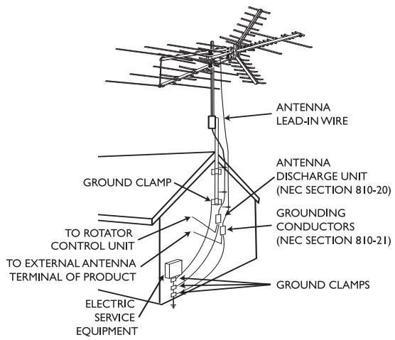
Antenna grounding and safety warning
- Outdoor antennas and lead-in conductors from antenna to a building, should not cross over open conductors of electric light or power circuits. They should be kept away from all circuits to avoid the possibility of accidental contact.
- Each conductor of a lead-in from an outdoor antenna should be connected with an antenna discharge unit. Antenna discharge units (or Lightning Arrestor) should be located outside the building or inside the building between the point of entrance of the lead-in and the TV, and as near as practical to the entrance of the conductors to the building.
Important Safety Notes
If you do not feel comfortable or competent to install this antenna we recommend that you seek the assistance of a qualified professional antenna installer.
Read the instructions for this device thoroughly before attempting installation.
The installation or dismantling of any antenna near power lines is dangerous. Each year hundreds of people are killed or injured while attempting to install or service antennas. For your safety and proper antenna installation, read and follow all safety precautions.
Choose an installation site for safety as well as performance.
All electric power lines, cable lines and telephone lines look alike. To be safe, assume ANY overhead line can kill you. Do not place an antenna where it could potentially fall on to, or blow into a power line. If in doubt call your electric provider. Let them review your site.
Outdoor antennas should be grounded with an approved
IMPORTANT READ BEFORE INSTALLATION
lighting arresting device. Local codes may apply. Use 8 AWG or larger ground wire.
Height or other restrictions on antennas may apply to your installation depending on your proximity to an airport, or local ordinances.
Take the time to plan your installation procedure. Do all assembly work on the antenna on the ground. Raise the completed antenna after assembly.
Do NOT work on a wet, snowy or windy day or if a thunderstorm is approaching. Do NOT use a metal ladder.
If the antenna assembly starts to fall, get away from it and let it fall. Remember that the antenna mast and cable are all excellent conductors of electrical current.
Do NOT install the antenna by yourself. Be sure that there are two other people available for help.
If any part of the antenna should come in contact with a power line . . . DON'T TOUCH IT OR TRY TO REMOVE IT YOURSELF. Call your local power company immediately. They will remove it.
Should an electrical accident occur . . . DON'T TOUCH THE PERSON IN CONTACT WITH THE POWER LINE, or you too can become electrocuted. Instead, use a DRY board, stick, or rope to push or pull the victim away from the power lines and antenna. Once clear, check the victim. If he has stopped breathing, immediately administer cardiopulmonary resuscitation (CPR) and stay with him. Have someone else call for medical help.
Install wire antennas high enough that they will not be "walked into" by people.
Do not install antenna wire(s) over or under utility lines.
Note: For final installation and connection of your antenna, additional hardware may be required. Before starting assembly, please read through the instructions carefully to determine your
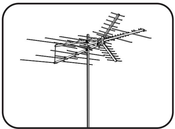
Parts included:
a UHF Boom-A 2
b.UHF Boom-B 2
c. VHF Boom-A 1
d. VHF Boom-B 2
e. Reflector Elements 2
f 46 Element 2
g. 50^ Element 2
h Tubing Brace 2
j Phasing Wire 2
k. Reflector Brackets 2
1 Pivot Brackets 4
n.Locking Brackets 4
p.End Caps 8
q. Screws (1-3/4") 5
r Screws (1-1/2") 10
s Screws (3/4") 2
t Lock Washers/ Washers . 6, 4
u. Wing-Nuts 17
v.Nuts 6
W.
Assembly
Band Separator 1
x U-Bolt 3
y.Cross Piece (for U-Bolt Assembly) 3
z Antenna Saddle 1
*Quantities listed include those which may already be attached to antenna
NOTE: Cable, mast and mounting brackets are not included.
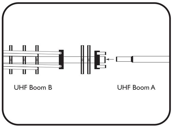
Assembly of UHF Portion
-
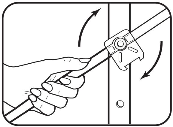
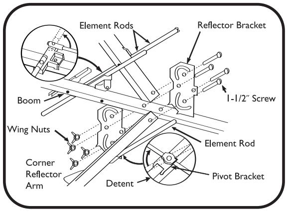
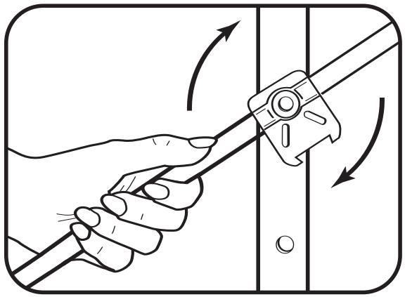
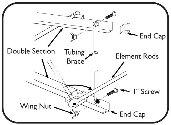
Rotate reflector element rods into place. NOTE: When rotating element rods, grasp close to pivot and relieve spring pressure on pivot bracket detents. Don't apply excess pressure to reflector element rods.
-
Insert UHF Boom-A into UHF Boom-B and secure using 1 - 1 / 2^ screw and lock washer.
- Attach Reflector Arm Mounting Brackets to assembled UHF Boom (previous step) using two 1-1/2" screws and wing-nuts. Ensure that rotation arcs in Reflector Arm Mounting Brackets face toward UHF Boom elements.
- Attach Corner Reflector Arms to Reflector Arm Mounting Brackets by sliding Reflector Arms between Mounting Brackets. Secure with 1 - 1 / 2" screw and wing-nuts. To fully secure Reflector Arms, snap into locking tabs and tighten screws.
Assembly of VHF Portion
- Rotate reflector element rods on VHF Boom-A and VHF Boom-B into place. NOTE: When rotating element rods, grasp close to pivot and relieve spring pressure on pivot bracket detents. Don't apply excess pressure to reflector element rods.

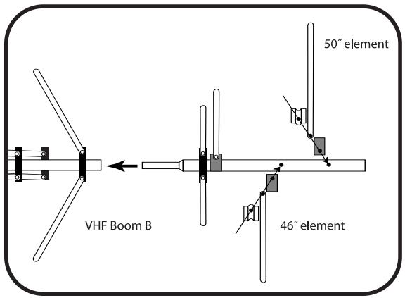
- Attach one 46^ Element to hole A in VHF Boom-B.
-
Attach one 50^ Element to VHF Boom-B. Repeat each steps with second boom for VHF Boom-B.
-
Insert VHF Boom-B into VHF Boom-A and secure using 1 - 1 / 2" screw and lock washers. Repeat steps for 2nd boom as well.
-
Attach tubing brace to rear of VHF Boom with 1- 1 / 2'' screws and wing-nuts.
-
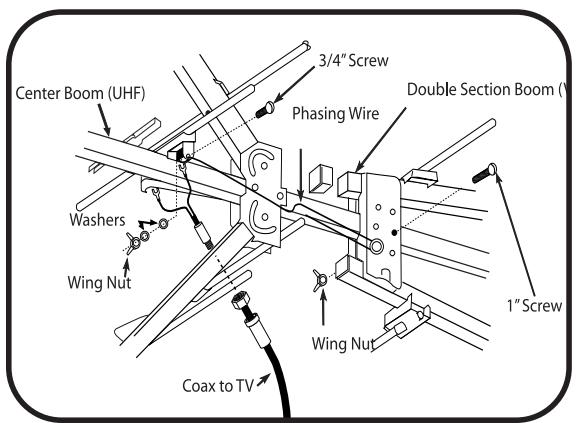
Slide UHF Boom through center slot of VHF Boom support block until hole A of UHF Boom aligns with hole B of VHF Boom. Secure with 1 - 1 / 2" screw and wing-nut.
- Attach phasing wire and lead-in wire to UHF antenna using 3 / 4'' screws, washers, and wing-nuts.
- Insert end caps at ends of all booms.
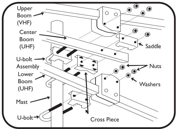
Mast Assembly (Mast not included)
- Assemble U-bolts to cross pieces.
- Use saddle on center of boom.
- Assemble U-bolt assemblies loosely to antenna.
- Insert mast through U-bolts.
-
Tighten U-bolts securely. All U-bolts should be on one side of mast.
-
Attach mast standoff to mast.
- Insert wire in standoff and tighten with pliers.
- Power lines should be as far away as possible.
- Assemble U-bolts in wall mounts with lock washers and nuts.
- Secure mounts to wall with wood screws.
- Separate mounts by at least two feet.
- Insert mast with assembled antenna through both U-bolts.
- Face antenna toward TV station.
- Tighten U-bolts securely.
- Wall mounts and chimney mounts are not included.
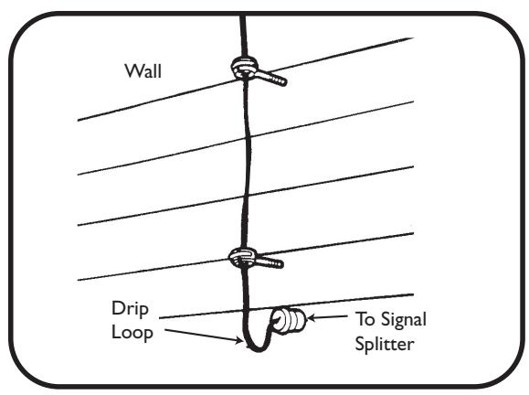
Lead-In Wire
- Attach lead-in wire to house with screw-type stand-offs.
- Tighten standoffs with pliers after wire is installed.
- Avoid sharp bends in lead-in wire.
- Form drip loop where wire enters wall.
- Wall mounts not included.
- Mounts, mast and standoffs are not included.
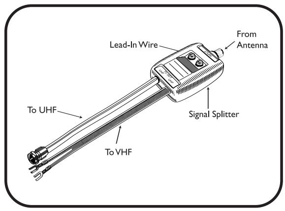
Band Separator
- Attach band separator to appropriate terminals on TV set.
- Attach antenna lead-in wire to band separator.
- An FM set or second TV set may be attached to second output of band separator.
NOTE: Band separator is only required for older TV sets with separate VHF/UHF inputs. For most newer sets, simply connect cable from antenna to 'F' input.
Technical Support
Limited Lifetime Warranty
The manufacturer warrants that this product shall be free from defects in material, workmanship and assembly, under normal use, in accordance with the specifications and warnings, for as long as you own this product. This warranty extends only to the original purchaser of the product, and is not transferable. Defective products, together with the dated proof of purchase, must be returned to the place of purchase for repair or replacement. THERE ARE NO OTHER EXPRESS WARRANTY. Incidental and consequential damages are disclaimed where permitted by law. This warranty gives you specific legal rights, and you may also have other rights which vary from state to state.
Assistance technique
Séparateur de bande
Specifications are subject to change without notice Trademarks are property of Philips Accessories and Computer Peripherals 2006© Philips Accessories and Computer Peripherals, Ledgewood, NJ USA
www.philips.com
313520200602
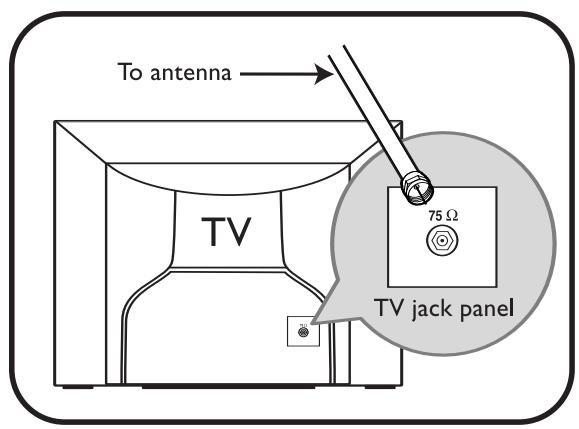
75 Ohm Coaxial Cable is the type of transmission cable used for cable TV or satellite service in your home. It is not affected by moisture or contact with with metal (drain pipes, aluminum siding, etc.). Coaxial cable has a much longer life than 300Ohm twinlead. Coaxial cable is also designed for minimal loss over longer cable runs and is shielded to reject interference. All TVs and VCRs manufactured today are equipped with direct connections for 75 Ohm coaxial cable.
Philips recommends the use of 75 Ohm RG-6 or RG-6 quad shield (best quality with lowest loss and best interference rejection) coaxial cable in the installation of your TV antenna. Our coax cable has been designed and manufactured to provide you with the best possible performance from your TV, VCR, and Audio / Home Theater system.
Standoffs and transformers needed for most normal installations with coaxial cable are included in this antenna package and installation kit. Philips coaxial cable is available separately in conveniently packaged lengths.
300 Ohm Twin Lead is 2 conductor flat cable that connects to your components with spade lug type connectors. It must be kept away from contact of the antenna mast, gutters, siding or any other metal objects.
Standoffs needed for most normal installations are included in this antenna package and installation kit. Philips twin lead cable is available separately in conveniently packaged lengths.
Provides wall mounting support for outdoor antennas.
Tools Needed:
Screwdriver, 1 / 4'' open end wrench.
Instructions:
I. Assemble U-bolts in wall mount brackets (as shown) with lock washers and hex-nuts. Do not tighten.
2. Secure wall mount brackets to wall with wood screws, making sure the wall mounts are approx. 2 ft. apart and vertically aligned.
3. Insert mast with assembled antenna through both U-bolts, checking to see that the mast is aligned vertically (straight). Tighten hex-nuts securely.
Wall Mount Contains:
- Safety Instructions
- Antenna grounding and safety warning
- Important Safety Notes
- Parts included:
- Assembly
- Assembly of UHF Portion
- Assembly of VHF Portion
- Mast Assembly (Mast not included)
- Lead-In Wire
- Band Separator
- Technical Support
- Limited Lifetime Warranty
- Assistance technique
- Séparateur de bande
- Tools Needed:
- Instructions:
- Wall Mount Contains:
Brand : PHILIPS
Model : SDV9011K
Category : TV Antenna