KM 405 - Plaque de cuisson MIELE - Notice d'utilisation et mode d'emploi gratuit
Retrouvez gratuitement la notice de l'appareil KM 405 MIELE au format PDF.

| Type d'appareil | Plaque de cuisson gaz |
| Nombre de foyers | 4 à 5 |
| Type de gaz | Gaz naturel ou gaz propane |
| Allumage | Électrique intégré |
| Matériau de la surface | Acier inoxydable ou verre trempé |
| Commandes | Manettes rotatives |
| Sécurité | Arrêt automatique en cas d'extinction |
| Dimensions (L x P) | Non précisé |
| Installation | Encastrable |
| Brûleurs | Brûleurs à haute efficacité |
| Accessoires inclus | Grilles en fonte |
| Consommation énergétique | Non précisé |
| Poids | Non précisé |
| Normes | Conforme aux normes de sécurité européennes |
| Garantie | Non précisé |
FOIRE AUX QUESTIONS - KM 405 MIELE
Questions des utilisateurs sur KM 405 MIELE
0 question sur cet appareil. Repondez a celles que vous connaissez ou posez la votre.
Poser une nouvelle question sur cet appareil
Téléchargez la notice de votre Plaque de cuisson au format PDF gratuitement ! Retrouvez votre notice KM 405 - MIELE et reprennez votre appareil électronique en main. Sur cette page sont publiés tous les documents nécessaires à l'utilisation de votre appareil KM 405 de la marque MIELE.
MODE D'EMPLOI KM 405 MIELE
Installation instructions
Gas hob
KM 404 / KM 405
KM 406
KM 414 / KM 417
To avoid the risk of accidents or damage to the appliance, it is
essential to read these
instructions before it is installed
and used for the first time.
en - GB
M.-Nr. 04 930 603
This appliance can be used in countries other than those specified on the appliance. It is, however, set up for connection to the gas and electricity supplies in the countries specified. For use in other countries please contact the Miele spare parts or customer service department in your country.
Das Gerät ist auch für den Gebrauch in anderen als auf dem Gerät angegebenen Bestimmungsländer zugelassen. Die landesspezifische Ausführung und die Anschlussart des Gerätes haben wesentlichen Einfluss auf den einwandfrei und sicheren Betrieb. Für den Betrieb in einem anderen als auf dem Gerät angegebenen Bestimmungsland wenden Sie sichitte an den für das Land zuständigen Kundendienst.
E El aparato está autorizzato para el uso en páíses发展模式 a los páíSES de destino indicados. La的操作ación especifica para cada País y el tipo de connexion del aparato influyen de forma decisiva en el functioningamento correcto y seguro. Para el functioningamento en un País不一样 al País de destino indicado en el aparato, consulte al Servicio Post-venta autorizzato para el País.
F Cet apparéil est également homologué dans des pays différents de ceux mentionnés sur l' apparéil. Pour que l' apparéil fonctionne parfaitement et en toute sécurité, il est important de-disposer de l'exécution spécifique au pays et du type de raccordement approprié. Pour le fonctionnement dans un pays autre que celui spécifique sur l' apparéil, veuillez vous adresser au service après-vente du pays où sera installé l' apparéil.
L'apparecchio può essere usatoanche in paesi diversi da quelloindicato sull'apparecchio stesso.Tuttavia,le varianti specifiche di un determinato paese e il tipo di allacciamento alla rete hanno un'importanza fondamentale per il suo sicuro e corretto funzionamento.Per questo se si vuole usare l'apparecchio in un paese diverso rivolgersi al servizio di assistenza tecnica Miele del paese in cui si intende uso.
NL Het apparaat is ook toegelaten voor gebruik in andere landen dan de landen die op het apparaat vermeld staan. De specifiekeuitvoering en de aansluitwijze zijn van groot belang voor het goed en veilig functioneren. Neem waarom contact op met de Technische Dienst van de fabrikant in uw land als u het apparaat in een land wilt gebruiken dat Niet op het apparaat vermeld staat.
Gas-heated appliances Safety precautions to take if you smell gas
- Turn off the gas emergency control valve immediately. This is usually located near the gas meter.
- Eliminate all sources of ignition in a safe manner. Do not smoke, light cigarette lighters or matches.
- Do not operate electrical lights or switches, i.e. do not switch them "On" or "Off".
- Open all doors and windows to ventilate the area.
- If the smell of gas persists, evacuate the building.
In the U.K you must now:
- Call TRANSCO (Tel: 0 800 111 999)
- Arrange for an appointment of a Corgi registered gas installer to visit the site (Tel: Talking pages 0 800 600 900)
In other countries please follow relevant country specific procedures on gas.
Warning and Safety instructions 6
Building in 6
Safety distance above appliances 7
Appliance dimensions 8
KM 404. 8
KM 405. 9
KM 406. 10
KM 414. 11
KM 417. 12
Worktop cut-out KM 404 / KM 405 / 406 13
Installation KM 404 / KM 405 / 406 14
Fitting the spacer bars and support brackets 14
Fixing the spacer bars. 15
Fixing the support brackets. 16
Granite worktops. 16
Building in the gas hob 16
Worktop cut-out KM 414 / KM 417 17
Installation KM 414 / KM 417 18
Fitting the spacer bars and support brackets 18
Fixing the spacer bars. 19
Fixing the support brackets. 20
Granite worktops. 20
Building in the gas hob 20
General 21
Electrical connection 22
Gas connection 24
KM 404 / KM 405 / KM 406 25
KM 414 / KM 417 25
Natural gas / liquid gas 25
Conversion to another type of gas 26
KM 404. 26
Jet table 26
Changing the jets 27
KM 405. 28
Jet table 28
Changing the jets 29
KM 406. 30
Jet table 30
Changing the jets 31
Check the first intake of air 34
KM 414. 35
Jet table 35
Changing the jets 36
KM 417. 37
Jet table 37
Changing the jets 38
Building in
Fit wall units and cooker hood before fitting the gas hob, to avoid damaging the hob.
The room in which the gas hob is installed must be at least 20m^3 in size with a door or window in it which can be opened to the outside air.
The veneer or laminate coatings of worktops (or adjacent kitchen units) must be treated with 100^ heat-resistant adhesive which will not dissolve or distort.
Any backmoulds must be of heat resistant material.
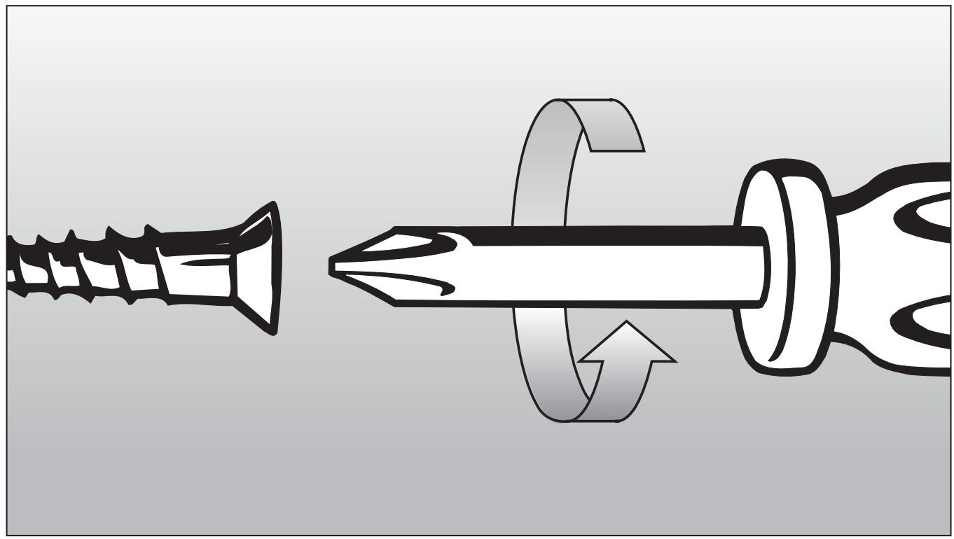
Ideally the hobs should be installed with plenty of space on either side.
There may be a wall at the rear and wall or tall units at one side. On the other side however, no unit or divider should stand higher than the hob.
Due to the heat radiated by the hob and to allow cooking fumes to dissipate it is essential that a minimum safety distance ① is maintained between the worktop cut-out and adjacent furniture, e.g. a tall unit, as follows:
100 mm with KM 404 / 405
250 mm with KM 406
200 mm with KM 414 / 417
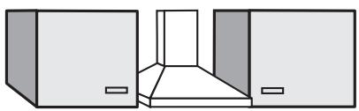
There must be a minimum safety distance of 50 ~mm between the hob and a back wall.
recommended

not recommended
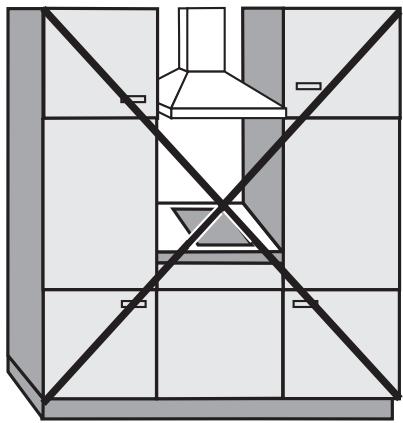
not allowed
An electric fryer must not be installed next to a gas hob, as the gas flames could ignite the fat in the fryer. It is essential to maintain a distance of at least 288 mm between these two appliances.
These appliances must not be installed over a dishwasher, washing machine, tumble dryer, refrigerator or freezer. The high temperatures radiated by hobs could damage the appliance below.
This equipment is not designed for maritime use or for use in mobile installations such as caravans, aircraft etc. However it may be suitable for such usage subject to a risk assessment of the installation being carried out by a suitably qualified engineer.
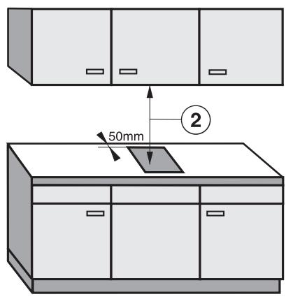
Safety distance above appliances
(2) A minimum safety distance must be maintained between the appliance and a cooker hood above it. See the cooker hood manufacturer's operating and installation instructions for details.
If the manufacturer's instructions are not available for the cooker hood, a minimum safety distance of at least 760~mm must be maintained. For any flammable objects, e.g. utensil rails, wall units etc. a minimum distance of at least 760~mm must be maintained between them and the hob below.
When two or more appliances are installed together below a cooker hood, e.g. a combiset and a gas wok combiset, which have different safety distances given in their installation instructions you should select the greater distance of the two.
All dimensions in this instruction booklet are given in mm.
Keep these instructions in a safe place and pass them on to any future owner of the appliance.
KM 404
(1) Support bracket
(2) Building in height plus 3 ~mm for fixing screw
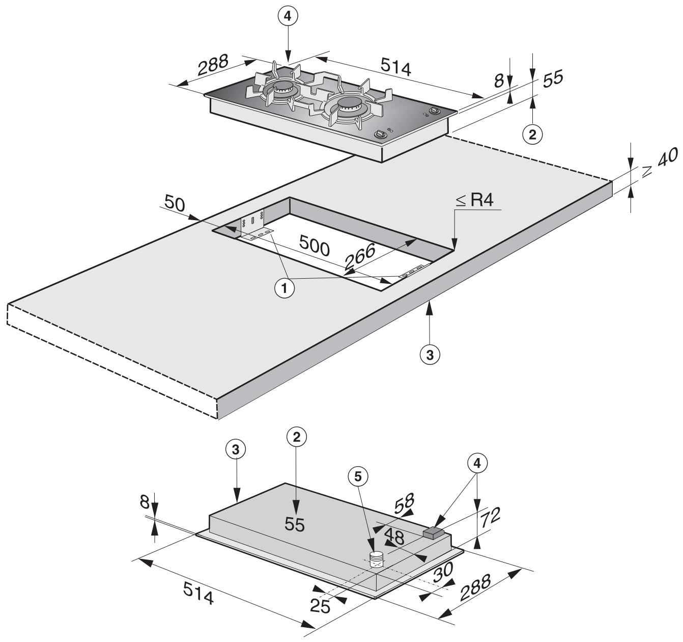
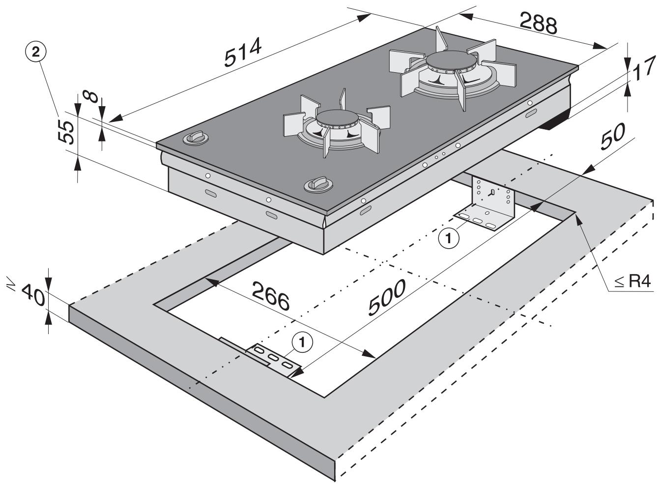
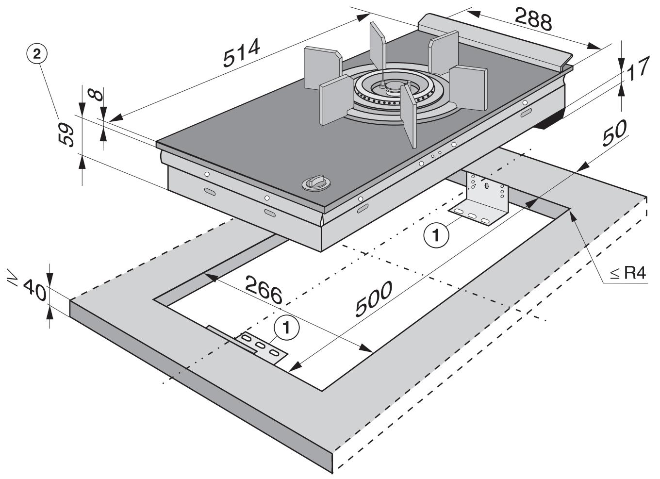
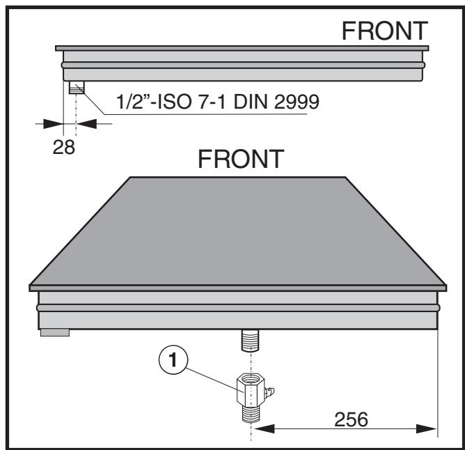
KM 405
(1) Support bracket
(2) Building in height plus 3 ~mm for fixing screw
(3) Front
(4) Building in height - Mains connection box
(5) Gas connection
KM 406
(1) Support bracket
(2) Building in height plus 3 ~mm for fixing screw
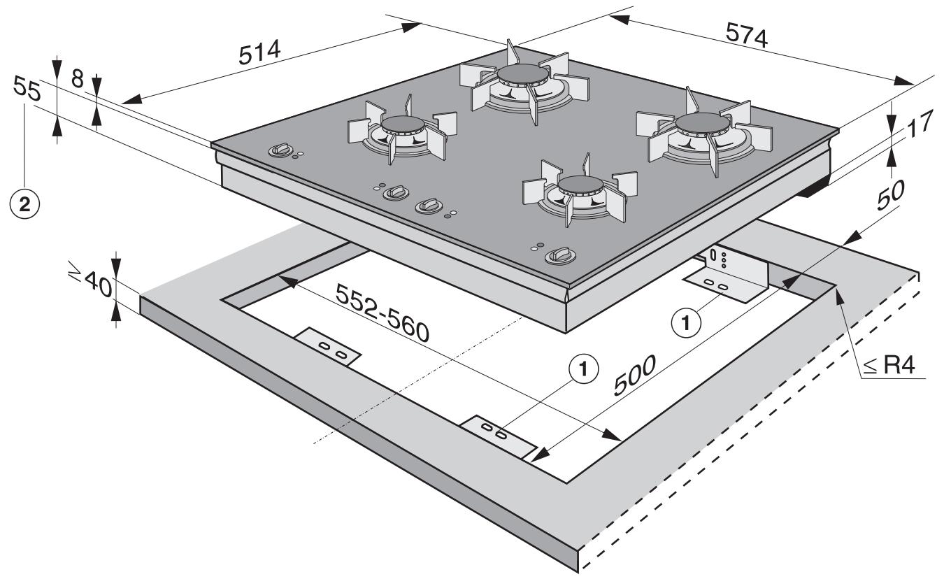
KM 414
(1) Support bracket
(2) Building in height plus 3 ~mm for fixing screw
KM 417
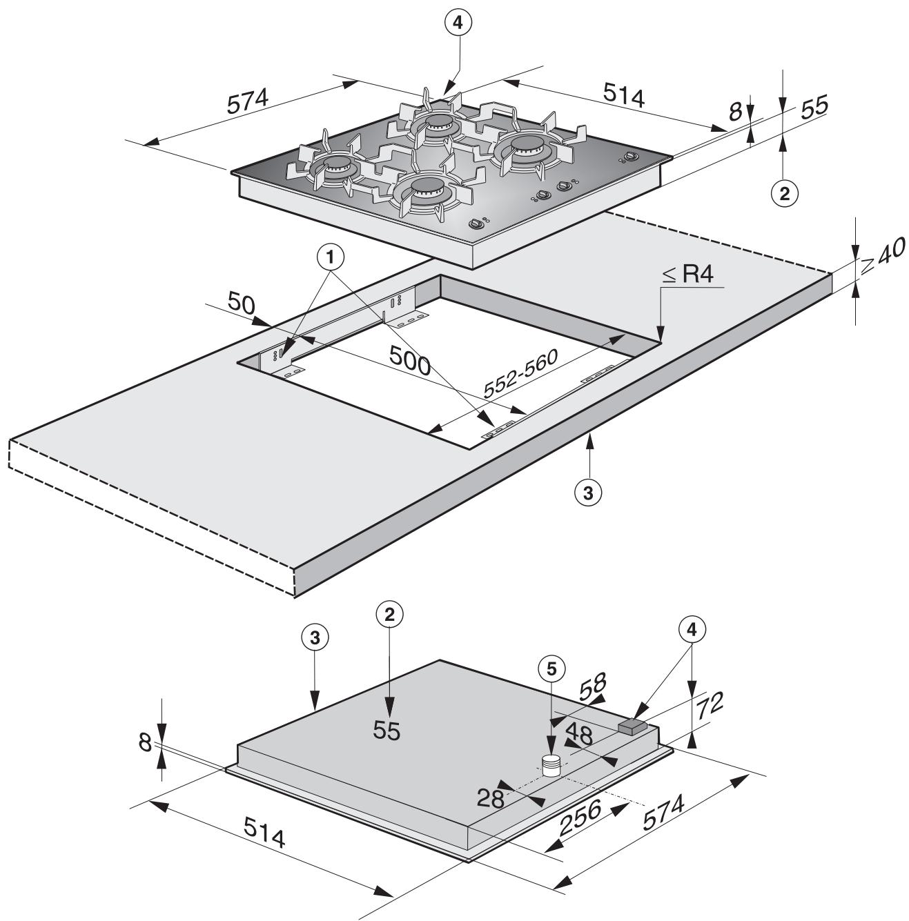
(1) Support bracket
(2) Building in height plus 3 ~mm for fixing screw
(3) Front
(4) Building in height - Mains connection box
(5) Gas connection
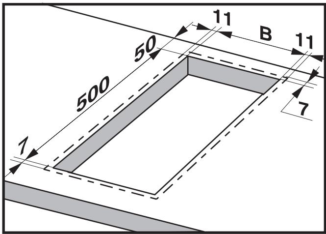
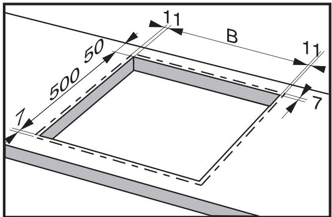
Dimensions 7 mm and 11 mm are the space taken up by the frame of the appliance on the worktop.
Make a cut-out for the hob in the worktop, paying attention to the appliance height. See "Appliance dimensions".
Dimension "B" applies to a combination of appliances and is shown on the chart.
There must be a minimum safety distance of 50~mm between the hob and the back wall and 100~mm distance from a side wall to the right or left of the hob ( 250~mm for KM 406).
(See "Warning and Safety instructions")
- Seal the cut surfaces with a suitable sealant to avoid swelling caused by moisture.
The materials used must be heat resistant.
| Number of appliances | Worktop cut-out KM 404 /405 /406 | |
| Depth in mm ± 1 mm | Width (= Dim. B) in mm ± 1 mm | |
| 1 | 500 | 266 |
| 2 | 500 | 554 |
| 3 | 500 | 842 |
| 4 | 500 | 1130 |
| 5 | 500 | 1418 |
| 6 | 500 | 1706 |
| 7 | 500 | 1994 |
Important:
The maximum tolerance for the worktop cut-out must not exceed ± 1 mm.
When building in several combiset appliances a spacer bar must be fitted between each unit. See "Fitting the spacer bars and support brackets".
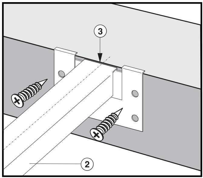
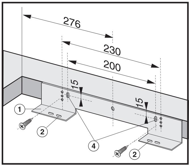
Fitting the spacer bars and support brackets
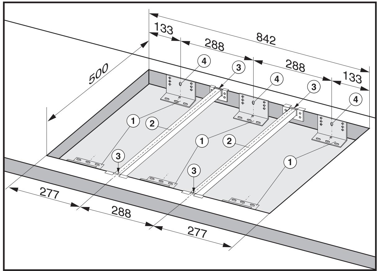
(1) Support brackets
② Spacer bars
(3) Gap between spacer bar and worktop.
(4) Drilling for a granite worktop.
Installation of several appliances
The illustration above shows an example of a worktop cut-out with spacer bars ② and support brackets ① for 3 appliances.
For more than 3 appliances, repeat dimension 288 ~mm .
The worktop cut-out dimensions for several appliances are shown in the table on the previous page.
Fix the spacer bars ② and the support brackets ① supplied to the positions indicated. See "Fixing the spacer bars" and "Fixing the support brackets".
Fixing the spacer bars
The spacer bar is only required when combined with another appliance.

Granite worktops
With granite worktops the spacer bars ② must be positioned and secured with strong double-sided adhesive tape. In addition, coat the edges with silicone and fill in the gap ③ .
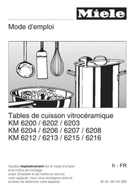
The screws are not required for granite tops.
Position the spacer bars ② in the positions shown in "Fitting the spacer bars and support brackets" so they are flush with the top edge of the cut-out and secure using the 3.5 × 25 ~mm screws supplied.
- Then fill in the gap ③ between the bars and the worktop with silicone from the tube supplied.
Fixing the support brackets
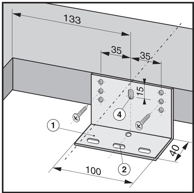
- Position the two support brackets supplied ① in the positions shown in "Fitting the spacer bars and support brackets" so they are flush with the top edge of the cut-out and secure using the 3.5 × 25 ~mm screws supplied. 2 screws are needed to secure each support bracket. The thickness of the worktop will determine which drill hole is used.
Please note that height of the support bracket for the KM 406 is different to that for the KM 404 and KM 405.
Granite worktops
On a granite worktop a hole must be drilled ④ at the position indicated to secure each support bracket.
Using a piece of strong, double-sided adhesive tape position the support brackets supplied ① at the positions indicated flush with the top edge of the worktop and secure each bracket with one screw in hole ④ as shown.
Building in the gas hob
- Place the gas hob in the prepared cut-out.
Feed the electricity connection cable through the cut-out and connect.
Make the gas connection. (see relevant section). - Secure the gas hob from below through the middle elongated hole ② in each support bracket using the two screws supplied. Carefully adjust the hob if necessary.
Dimensions 7 mm and 11 mm are the space taken up by the frame of the appliance on the worktop.
Make a cut-out for the hob in the worktop.
Dimension "B" applies to a combination of appliances and is shown on the chart.
There must be a minimum safety distance of 50~mm between the hob and the back wall and 200~mm distance from a side wall to the right or left of the hob. (See "Warning and safety instructions").
- Seal the cut surfaces with a suitable sealant to avoid swelling caused by moisture.
The materials used must be heat resistant.
| Worktop cut-out KM 414 / 417 | ||
| Depth in mm ± 1 mm | Width (= Dim. B) in mm ± 1 mm | |
| 1 hob | 500 | 552-560 |
| Worktop cut-out KM 414 / 417 + 288 mm wide appliances | ||
| Number of appliances | Depth in mm ±1 mm | Width (= Dim. B) in mm ±1 mm |
| KM 414/417 + 1 | 500 | 840 |
| KM 414/417 + 2 | 500 | 1 128 |
| KM 414/417 + 3 | 500 | 1 416 |
| KM 414/417 + 4 | 500 | 1 704 |
Important:
The maximum tolerance for the worktop cut-out must not exceed ± 1 mm.
When building in several hobs a spacer bar must be fitted between each unit. See "Fitting spacer bars and support brackets".
Narrow combiset appliances (288 mm wide) can be installed to the left or right hand side of the KM 414 / KM 417.
Fitting the spacer bars and support brackets
KM 414 / KM 417 with 2 appliances 288 mm wide
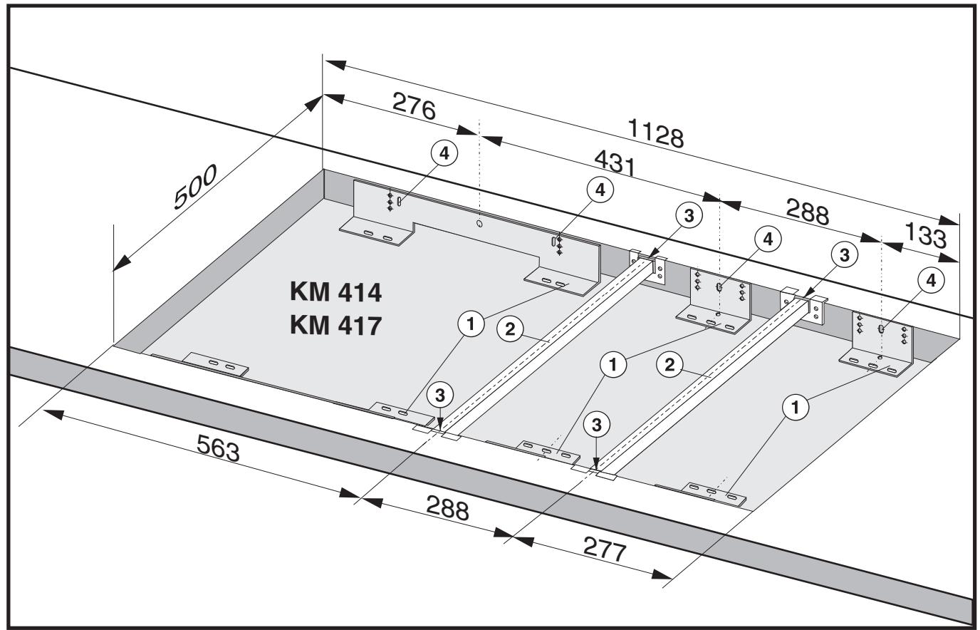
(1) Support brackets
② Spacer bars
Installation of several appliances
The illustration above shows an example of a worktop cut-out with spacer bars ② and support brackets ① for 3 appliances.
For more than 3 appliances, repeat dimension 288 ~mm .
The worktop cut-out dimensions for several appliances are shown in the table on the previous page.
(3) Gap between spacer bar and worktop.
(4) Drilling for a granite worktop.
Fix the spacer bars ② and the support brackets ① supplied to the positions indicated. See "Fixing the spacer bars" and "Fixing the support brackets".
Fixing the spacer bars
The spacer bar is only required when combined with a 288 mm wide combiset appliance.
Granite worktops
With granite worktops the spacer bars ② must be positioned and secured with strong double-sided adhesive tape. In addition, coat the edges with silicone and fill in the gap ③ .
The screws are not required for granite tops.
Position the spacer bars ② in the positions shown in "Fitting the spacer bars and support brackets" so they are flush with the top edge of the cut-out and secure using the 3.5 × 25 ~mm screws supplied.
- Then fill in the gap ③ between the bars and the worktop with silicone from the tube supplied.
Fixing the support brackets
- Position the two support brackets supplied ① in the positions shown in "Fitting the spacer bars and support brackets" so they are flush with the top edge of the cut-out and secure using the 3.5 × 25 ~mm screws supplied. 2 screws are needed to secure each support bracket. The thickness of the worktop will determine which drill hole is used.
Granite worktops
On a granite worktop a hole must be drilled ④ at the position indicated to secure each support bracket.
Using a piece of strong, double-sided adhesive tape position the support brackets supplied ① at the positions indicated flush with the top edge of the worktop and secure each bracket with one screw in hole ④ as shown.
Building in the gas hob
- Place the gas hob in the prepared cut-out.
Feed the electricity connection cable through the cut-out and connect.
Make the gas connection. (see relevant section). - Secure the gas hob from below through the middle elongated hole ② in each support bracket using the four screws supplied. Carefully adjust the hob if necessary.
Important
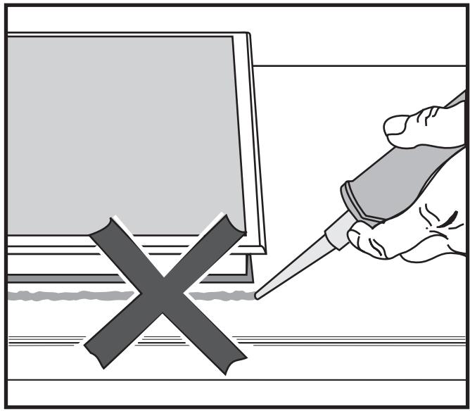
Under no circumstances should sealant find its way between the frame of the top part of the hob and the worktop.
This could cause difficulties if the hob ever needs to be taken out for servicing, (possibly leading to damage to the frame and worktop). The sealing strip under the edge of the top part of the hob provides a sufficient seal for the worktop.
All electrical work should be carried out by a suitably qualified and competent person, in strict accordance with current local and national safety regulations (BS 7671 in the UK).
Installation, repairs and other work by unqualified persons could be dangerous. The manufacturer cannot be held liable for unauthorised work.
Ensure power is not supplied to the appliance until after installation or repair work has been carried out.
The appliance must only be operated when built-in. This is to ensure that all electrical parts are shielded. Live parts must not be exposed.
Do not connect the appliance to the mains electricity supply by an extension lead. These do not guarantee the required safety of the appliance.
Please make sure that the connection data quoted on the data plate match the household mains supply.
Connection should be made via a suitable isolator or a double pole fused spur connection unit which complies with national and local safety regulations and the on/off switch should be easily accessible after the appliance has been built in.
If the switch is not accessible after installation (depending on country) an additional means of disconnection must be provided for all poles.
For extra safety it is advisable to install a residual current device (RCD) with a trip current of 30 ~mA .
When switched off there must be an all-pole contact gap of 3mm in the isolator switch (including switch, fuses and relays).
Important U.K.
This appliance is supplied for connection to a single phase 230-240 V 50 Hz supply with a 3-core cable.
The wires in the mains lead are coloured in accordance with the following code:
$$ \mathrm {G r e e n / y e l l o w} = \mathrm {e a r t h} $$
$$ \text {B l u e} \quad = \text {n e u t r a l} $$
$$ \begin{array}{l l} \text {B r o w n} & = \text {l i v e} \end{array} $$
WARNING
THIS APPLIANCE MUST BE EARTHED
Important
The electrical safety of this appliance can only be guaranteed when continuity is complete between it and an effective earthing system, which complies with current local and national safety regulations. It is most important that this basic safety requirement is present and regularly tested and where there is any doubt, the electrical wiring in the home should be tested by a qualified electrician. The manufacturer cannot be held liable for the consequences of an inadequate earthing system such as an electric shock.
The manufacturer cannot be held liable for damage which is the direct or indirect result of incorrect installation or connection.
Connection to the gas supply, or conversion from one type of gas to another should only be undertaken by an approved and registered gas installer in strict accordance with local and national safety and building regulations, (e.g. Corgi registered in the U.K.) Every appliance should have its own isolating valve and test point.
Check with your local gas supplier about the type of gas and its calorific value, and compare this information with the type of gas quoted on the hob data plate.
The installer is responsible for ensuring that the appliance functions correctly when installed.
Depending on country, the hob is supplied ready for connection to natural gas or liquid gas (refer to label on the appliance).
United Kingdom:
GB II 2 H 3+ 20 mbar, 28-30/37 mbar
Ireland:
IE II 2 H 3+ 20 mbar, 28-30/37 mbar
Depending on country a set of jets for conversion to natural or liquid gas may be included with the hob.
Please contact your dealer or agent for the appropriate conversion jets if necessary.
Connection
Conversion to another type of gas is described under the relevant Section.
The gas connection must be installed so that connection can be made either from inside or outside the kitchen unit, and the isolating valve must be easily accessible and visible (by opening one of the kitchen unit doors, if necessary).
A test for possible leakages must be carried out after installation.
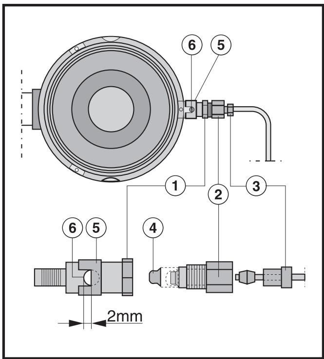
Safety regulations demand that a pressure test point is installed near a gas hob to allow an engineer to test the pressure, following servicing.
KM 404 / KM 405 / KM 406
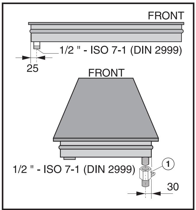
(1) Connection with test nipple specifically for GB
KM 414 / KM 417
(1) Connection with test nipple specifically for GB
Natural gas / liquid gas
- An appropriate rigid connection and isolating valve must be installed for final connection.
- The gas connection must be so sited that it is not adversely heated when the appliance is in operation.
In particular ensure that hot gas exhaust cannot touch the gas pipe or appliance connections.
After installing the appliance the gas burners have to be set for local conditions.
When the gas hob has been installed it is essential to check that neither the gas pipe nor the electricity cable is in contact with hot parts of the appliance or hot gas exhaust, otherwise heat damage to the pipe and cable could occur.
KM 404
When converting to another type of gas, the main jets and the small jets of all burners must be changed.
Nominal rating for all gas types with the burner full on
| Gas type | kW | |
| Normal burner | Natural H Liquid | 1.75 1.75 / 127 g/h |
| Fast burner | Natural H Liquid | 3,00 3.00 / 219 g/h |
| Total output | Natural H Liquid | 4.75 4.75 / 345 g/h |
Nominal rating at low setting
| Gas type | kW | |
| Normal burner | Natural H Liquid | 0.30 0.30 |
| Fast burner | Natural H Liquid | 0.50 0.50 |
Screw in the new jets according to the following table.
Jet table
for U.K. and IE
| Main jet Ø | Low setting jet Ø | |
| Natural gas | ||
| Normal burner | 1.00 | 0.42 |
| Fast burner | 1.29 | 0.54 |
| Liquid gas | ||
| Normal burner | 0.65 | 0.27 |
| Fast burner | 0.85 | 0.36 |
The jet markings refer to 1 / 100 ~mm of the jet diameter.
Contact your local gas supplier if the natural gas connection pressure is less than 18 mbar or higher than 25 mbar.
Changing the jets
Disconnect the gas hob from the electricity supply by switching off at the socket and withdrawing the plug or by removing the mains fuse.
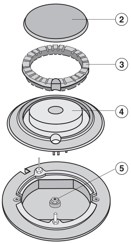
Changing the main jets
Take off the pan support, the burner cover ②, the burner ring ③ and the burner head ④.
Using an SW7 socket spanner unscrew the main jet ⑤.
Change the main jet.
- Reassemble the burner head, burner ring and burner cover in the correct order.
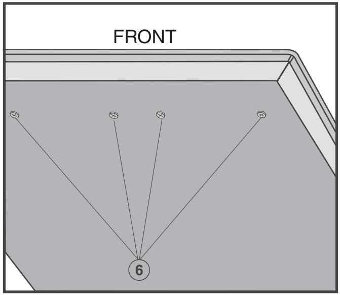
Changing the small jets

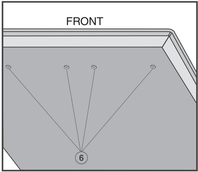
■ Guide a screwdriver through the holes in the lower casing of the hob and loosen the small jets ⑥.
Pull the jets out with a pair of pointed pliers.
Put in the new jets with a pair of pointed pliers.
- Secure the new jets with a screwdriver.
Finally secure the jets against inadvertent loosening with sealing wax.
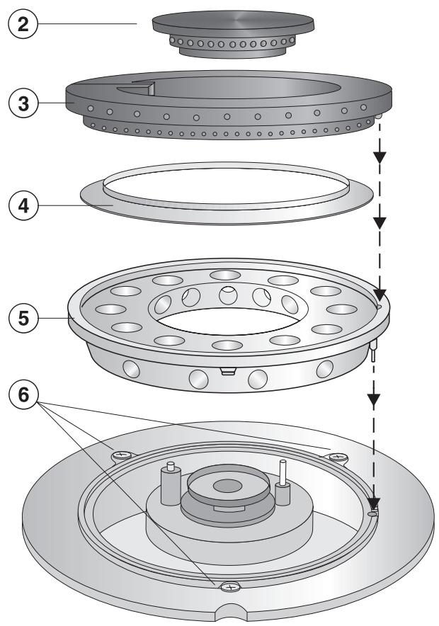
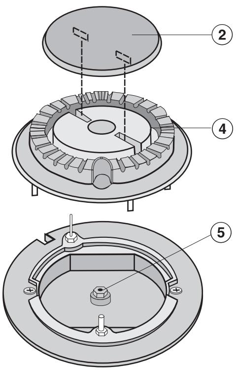
KM 405
When converting to another type of gas, the main jets and the small jets of all burners must be changed.
Nominal rating for all gas types with the burner full on
| Gas type | kW | |
| Normal burner | Natural H Liquid | 1.75 1.75 / 127 g/h |
| Fast burner | Natural H Liquid | 3.00 3.00 / 219 g/h |
| Total output | Natural H Liquid | 4.75 4.75 / 345 g/h |
Nominal rating at low setting
| Gas type | kW | |
| Normal burner | Natural H Liquid | 0.30 0.30 |
| Fast burner | Natural H Liquid | 0.50 0.50 |
Screw in the new jets according to the following table.
Jet table
for U.K. and IE
| Main jet Ø | Low setting jet Ø | |
| Natural gas | ||
| Normal burner | 1.00 | 0.42 |
| Fast burner | 1.29 | 0.54 |
| Liquid gas | ||
| Normal burner | 0.65 | 0.27 |
| Fast burner | 0.85 | 0.36 |
The jet markings refer to 1 / 100 ~mm of the jet diameter.
Contact your local gas supplier if the natural gas connection pressure is less than 18 mbar or higher than 25 mbar.
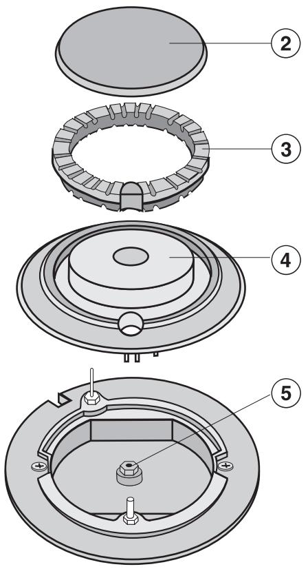
Changing the jets
Disconnect the gas hob from the electricity supply by switching off at the socket and withdrawing the plug or by removing the mains fuse.
Changing the main jets
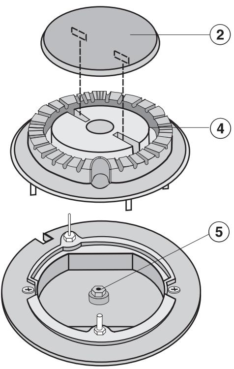
Take off the pan support, the burner cover ② and the burner head ④.
Using an SW7 socket spanner unscrew the main jet ⑤.
Change the main jet.
- Reassemble the burner head and burner cover in the correct order.
Changing the small jets
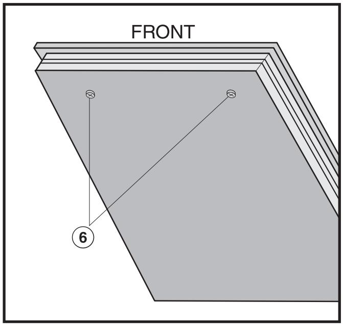
■ Guide a screwdriver through the holes in the lower casing of the hob and loosen the small jets ⑥.
Pull the jets out with a pair of pointed pliers.
Put in the new jets with a pair of pointed pliers.
- Secure the new jets with a screwdriver.
Finally secure the jets against inadvertent loosening with sealing wax.
KM 406
When converting to another type of gas, the main jets and the small jets of all burners must be changed.
Nominal rating at high setting
| Gas type | KW |
| Natural | 5.90 |
| Liquid | 5.40 / 394 g/h |
Jet table
For U.K. and IE
| Main jet Ø | Low setting jet Ø | |
| Natural gas | 1.85 | 0.88 / 0.40 Nr. 34 |
| Liquid gas | 1.12 | 0.52 / 0.23 Nr. 7 |
Nominal rating at low setting
| Gas type | KW |
| Natural | 0.25 |
| Liquid | 0.25 |
The jet markings refer to 1 / 100 ~mm of the jet diameter.
Contact your local gas supplier if the natural gas connection pressure is less than 18 mbar or higher than 25 mbar.
Screw in the new jets according to the following table.
Changing the jets
Disconnect the gas hob from the electricity supply by switching off at the socket and withdrawing the plug or by removing the mains fuse.
Take off the pan support, small burner cap ②, large burner cap ③, burner collar ring ④ and the large burner cap base ⑤.
Use a (T20) Torx screwdriver to unscrew the 3 Torx screws (M4).
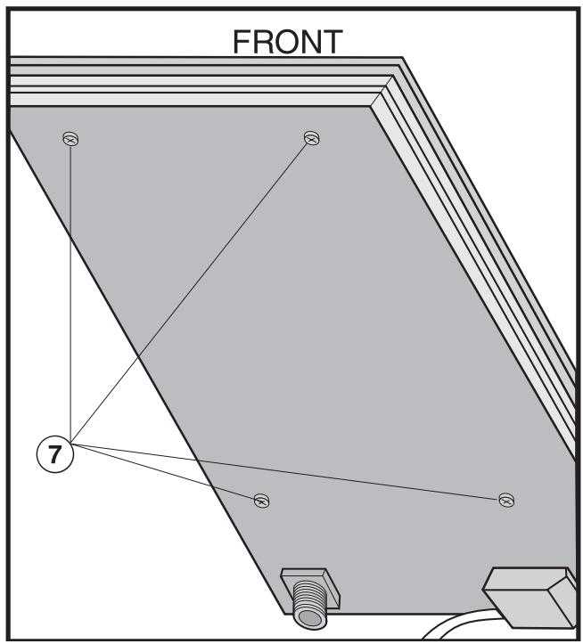
Pull the control knob for the gas burner upwards and off.
- Use a (T20) Torx screwdriver to unscrew the 4 Torx screws ⑦ (M4) in the lower part of the hob housing.
- Lift off the top part of the hob keeping it level.
Changing the main jet
Changing the small jets
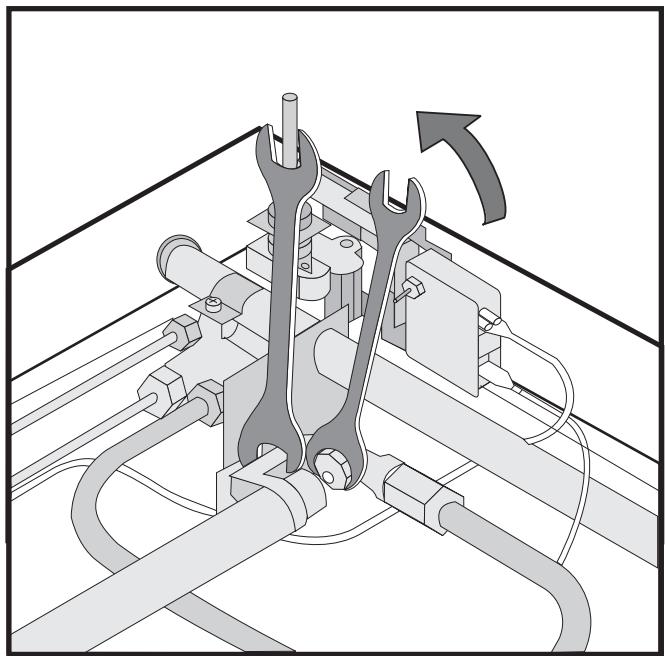
- Use an SW 10 socket spanner to loosen the main jet from its holder, by turning anti-clockwise. At the same time use an SW 13 spanner to counterclock.
Screw in the new main jets, once again using the spanner to counterchold.
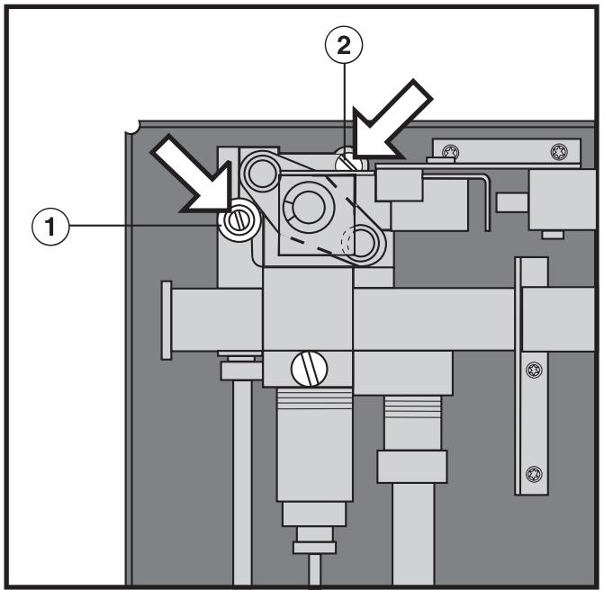
(1) Small jet with smaller jet diameter (e.g. for liquid gas: 0.20).
② Small jet with larger jet diameter (e.g. for liquid gas: 0.46).
Using a small screwdriver, unscrew both small jets in the gas fitting.
Pull the jets out with a pair of pointed pliers.
- Select the jets as shown in the table and fit, reversing the procedure, and secure.
Changing the jet for the inner burner
(4) jet disc (main jet for the inner burner)
⑤ air sleeve
(6) air vent
- Remove screw ③ from fitting ② with an SW8 spanner and use an SW12 spanner to countercold.
- Then remove the screw fitting ② from ① with an SW12 spanner and use another SW12 spanner to countercold.
Take out the jet disc ④ held in ① and replace with the correct jet disc (see jet table). - Move air sleeve ⑤ to adjust the two air vents ⑥ to the opening illustrated (2 mm).
- Assemble the removed parts in the reverse order and check for leaks by operating the burner without the upper part of the hob in place (use a match to ignite the flame).
Check the first intake of air
If this is not the case, loosen the securing screw, re-position the air sleeve and then tighten the securing screw.
Finally secure the jets against inadvertent loosening with sealing wax.
- Re-assemble the hob in the reverse order.
The flame must not go out in the lowest setting, or when the control is turned quickly from a high to a low setting.
In the highest setting the flame must have a distinctive and visible core.
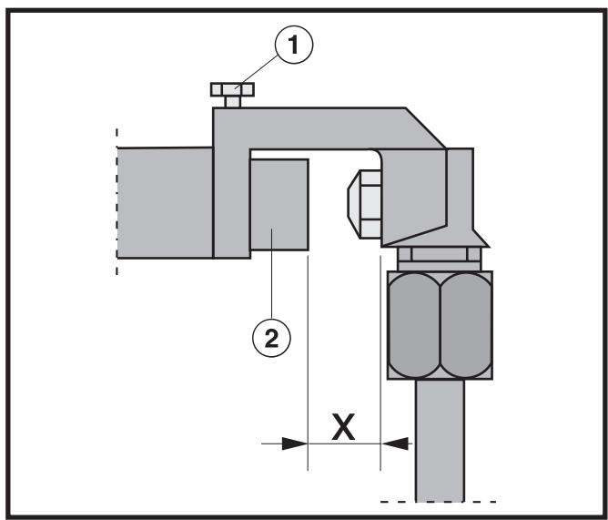
(1) Securing screw
② Air sleeve
Gap X must measure:
6 mm for Natural gas
13 mm for Liquid gas
KM 414
When converting to another type of gas, the main jets and the small jets of all burners must be changed.
Nominal rating for all gas types with the burner full on
| Gas type | kW | |
| Normal burner | Natural H Liquid | 1.75 1.75 / 127 g/h |
| Fast burner | Natural H Liquid | 3.00 3.00 / 219 g/h |
| Total output | Natural H Liquid | 9.50 9.50 / 690 g/h |
Jet table
for U.K. and IE
| Main jet Ø | Low setting jet Ø | |
| Natural gas | ||
| Normal burner | 1.00 | 0.42 |
| Fast burner | 1.29 | 0.54 |
| Liquid gas | ||
| Normal burner | 0.65 | 0.27 |
| Fast burner | 0.85 | 0.36 |
The jet markings refer to 1 / 100 ~mm of the jet diameter.
Contact your local gas supplier if the natural gas connection pressure is less than 18 mbar or higher than 25 mbar.
Nominal rating at low setting
| Gas type | kW | |
| Normal burner | Natural H Liquid | 0.30 0.30 |
| Fast burner | Natural H Liquid | 0.50 0.50 |
Screw in the new jets according to the following table.
Changing the jets
Disconnect the gas hob from the electricity supply by switching off at the socket and withdrawing the plug or by removing the mains fuse.
Changing the main jet
Take off the pan support, the burner cover ②, the burner ring ③ and the burner head ④.
Using an SW7 socket spanner unscrew the main jet ⑤.
Change the main jet.
- Reassemble the burner head, burner ring and burner cover in the correct order.
Changing the small jet
Guide a screwdriver through the holes in the lower casing of the hob and loosen the small jets ⑥.
Pull the jets out with a pair of pointed pliers.
Put in the new jets with a pair of pointed pliers.
- Secure the new jets with a screwdriver.
Finally secure the jets against inadvertent loosening with sealing wax.
KM 417
When converting to another type of gas, the main jets and the small jets of all burners must be changed.
Nominal rating for all gas types with the burner full on
| Gas type | kW | |
| Normal burner | Natural H Liquid | 1.75 1.75 / 127 g/h |
| Fast burner | Natural H Liquid | 3.00 3.00 / 219 g/h |
| Total output | Natural H Liquid | 9.50 9.50 / 690 g/h |
Jet table
for U.K. and IE
| Main jet Ø | Low setting jet Ø | |
| Natural gas | ||
| Normal burner | 1.00 | 0.42 |
| Fast burner | 1.29 | 0.54 |
| Liquid gas | ||
| Normal burner | 0.65 | 0.27 |
| Fast burner | 0.85 | 0.36 |
The jet markings refer to 1 / 100 ~mm of the jet diameter.
Contact your local gas supplier if the natural gas connection pressure is less than 18 mbar or higher than 25 mbar.
Nominal rating at low setting
| Gas type | kW | |
| Normal burner | Natural H Liquid | 0.30 0.30 |
| Fast burner | Natural H Liquid | 0.50 0.50 |
Screw in the new jets according to the following table.
Changing the jets
Disconnect the gas hob from the electricity supply by switching off at the socket and withdrawing the plug or by removing the mains fuse.
Changing the main jets
Take off the pan support, the burner cover ② and the burner head ④.
Using an SW7 socket spanner unscrew the main jet ⑤.
- Change the main jet.
Reassemble the burner head and burner cover in the correct order.
Changing the small jets
■ Guide a screwdriver through the holes in the lower casing of the hob and loosen the small jets ⑥.
Pull the jets out with a pair of pointed pliers.
Put in the new jets with a pair of pointed pliers.
- Secure the new jets with a screwdriver.
Finally secure the jets against inadvertent loosening with sealing wax.
United Kingdom
Miele Co. Ltd.
Fairacres, Marcham Road
Abingdon, Oxon, OX14 1TW
Tel: (01235) 554455
Fax: (01235) 554477
Customer Contact Centre Tel: (08707) 554466
E-mail: info@miele.co.uk
Internet: www.miele.co.uk
Australia
Miele Australia Pty. Ltd.
A.C.N. 005635398
1 Gilbert Park Drive, Knoxfield, VIC 3180
Tel: (03) 9764 7130
Fax: (03) 9764 7149
Internet: www.miele.com.au
China
Miele Shanghai Rep. Office
Room 4105 - 6, 41* Floor
Plaza 66, 1266 Nan-Jing Road/ West
Shanghai 200040
Tel: +86 21 6288 4200
Fax: +86 21 6288 4100
E-mail: mieleshanghai@cn.miele.com
Internet: www.miele.cn
Hong Kong
Miele (Hong Kong) Limited
AIA Plaza, 24" Floor
18 Hysan Avenue
Causeway Bay
Tel: +852- 2610-1331
Fax: +852-2610-1013
E-mail: mielehk@miele.com.hk
Internet: www.miele.hk
Ireland
Miele Ireland Ltd.
Broomhill Road, Tallaght, Dublin 24
Tel: (01) 461 0710
Fax: (01) 461 07 97
E-Mail: info@miele.ie
Internet: www.miele.ie
New Zealand
Miele New Zealand Limited
Unit L, 10-20 Sylvia Park Road
Mt. Wellington, 1060, Auckland, NZ
Tel: 0800 264353
Fax: 0800 463453
Internet: www.miele.co.nz
South Africa
Miele (Pty) Ltd
63 Peter Place, Bryanston 2194
P.O. Box 69434, Bryanston 2021
Tel: +27 (0) 11 548-1900
Fax: +27 (0) 11 548-1935
E-mail: info@miele.co.za
Internet: www.miele.co.za
Singapore
Miele Southeast Asia
Miele Pte. Ltd.
163 Penang Road
04 - 02/03 Winsland House II
Singapore 238463
Tel: +65 6735 1191
Fax: +65 6735 1161
E-Mail: infosea@miele.com.sg
Internet: www.miele.sg
United Arab Emirates
Miele Appliances Ltd.
P.O.Box 114782
Gold & Diamond Park
Sheikh Zayed Road
Building 6 / Offices Nos. 6-214 to 6-220
Dubai
Tel: +971-4-341 84 44
Fax: +971-4-341 88 52
E-Mail: info@miele.ae
Internet: www.miele.ae