IR Quattro HD2 COM1 - Détecteur de mouvements STEINEL - Notice d'utilisation et mode d'emploi gratuit
Retrouvez gratuitement la notice de l'appareil IR Quattro HD2 COM1 STEINEL au format PDF.
| Caractéristiques techniques | Détecteur de mouvements infrarouge, portée jusqu'à 20 mètres, angle de détection de 360°. |
|---|---|
| Utilisation | Idéal pour la détection de mouvements dans les espaces intérieurs et extérieurs, notamment pour l'éclairage automatique. |
| Maintenance et réparation | Vérifier régulièrement le bon fonctionnement, nettoyer les capteurs pour éviter les fausses détections. |
| Sécurité | Conforme aux normes de sécurité électrique, installation recommandée par un professionnel pour éviter les risques. |
| Informations générales | Compatible avec divers systèmes d'éclairage, garantie constructeur de 2 ans. |
FOIRE AUX QUESTIONS - IR Quattro HD2 COM1 STEINEL
Questions des utilisateurs sur IR Quattro HD2 COM1 STEINEL
0 question sur cet appareil. Repondez a celles que vous connaissez ou posez la votre.
Poser une nouvelle question sur cet appareil
Téléchargez la notice de votre Détecteur de mouvements au format PDF gratuitement ! Retrouvez votre notice IR Quattro HD2 COM1 - STEINEL et reprennez votre appareil électronique en main. Sur cette page sont publiés tous les documents nécessaires à l'utilisation de votre appareil IR Quattro HD2 COM1 de la marque STEINEL.
MODE D'EMPLOI IR Quattro HD2 COM1 STEINEL
.steinel
DE
GB
natural_image
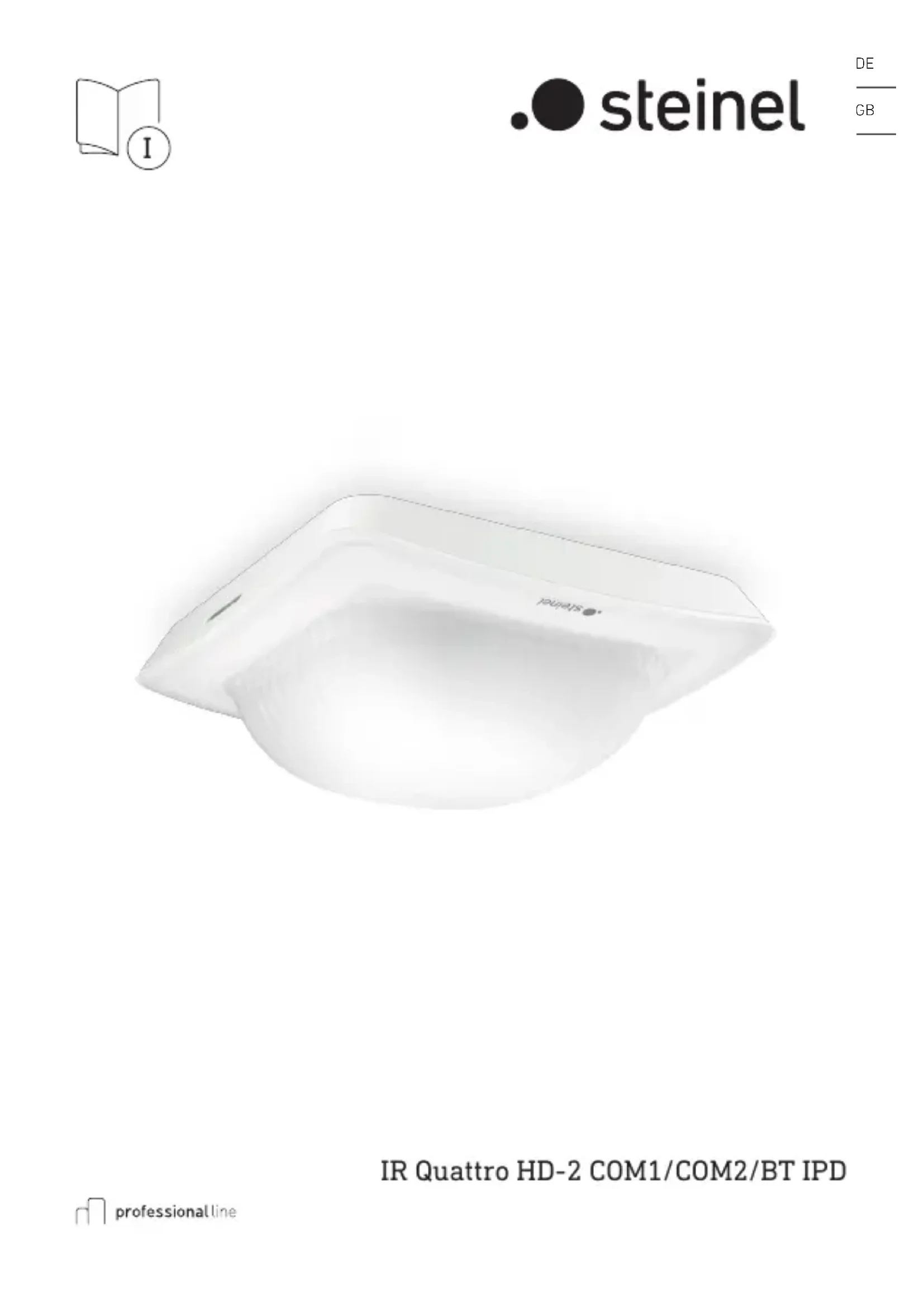
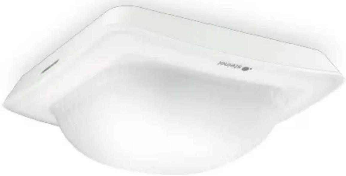
White rectangular electronic device with a circular button labeled 'TALWATS' (no additional text or symbols visible)IR Quattro HD-2 COM1/COM2/BT IPD

DE .... 9 Textteil beachten!
GB .... 17 Follow written instructions!
3.1 COM1/COM2/BT IPD UP
natural_image
Isometric line drawing of a rectangular device with a central circular cutout (no text or symbols)3.2
text_image
103 mm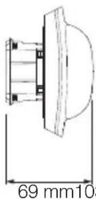
text_image
69 mm1033.3
text_image
Technical diagram of a device with labeled components A, B, C, D, and E showing internal structure and detail views.3.4 COM1/COM2/BT IPD AP
natural_image
Isometric line drawing of a 3D rectangular block with a central cutout (no text or symbols)3.7
text_image
2,8 m 9 m 9 m 24 m 24 m3.5
text_image
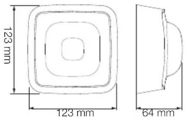
123 mm 123 mm 64 mm4.1 COM 1
text_image
S N ↓ L < 50m L N S3.6
text_image
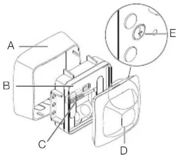
A B C D E4.2 COM 2
text_image
S N ↓ L B1 B0 < 50m L N4.3 BT IPD
text_image
Safety warning symbol and electrical circuit diagram showing lightning bolt, switch, and battery with current direction arrow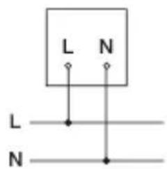
text_image
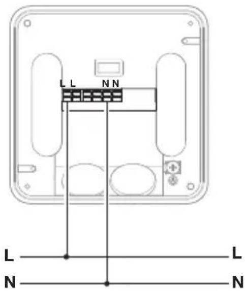
L N L N4.4 COM 1 AP
text_image
LL SNN < 50m L L N N4.5 COM 2 AP
text_image
LL SNN B1 B0 < 50m L N L N4.6 BT IPD AP
text_image
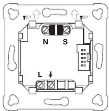
L L N L N L N4.7 COM 1 UP
text_image
T N S L4.8 COM 2 UP
text_image
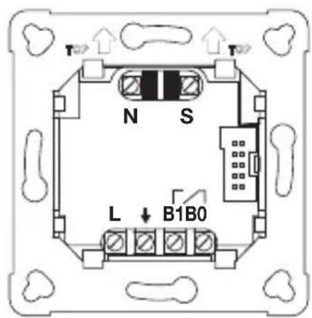
N S L ↓ B1B0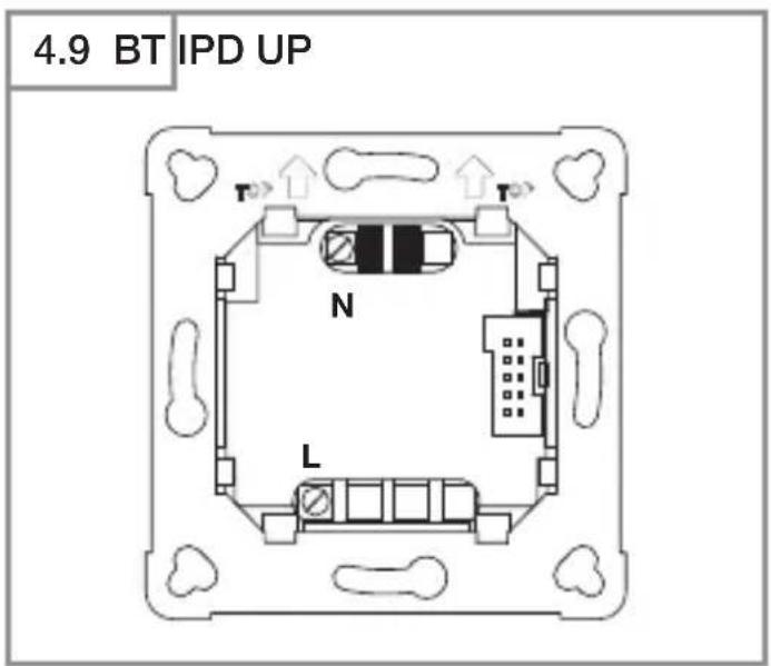
text_image
4.9 BT IPD UP T N L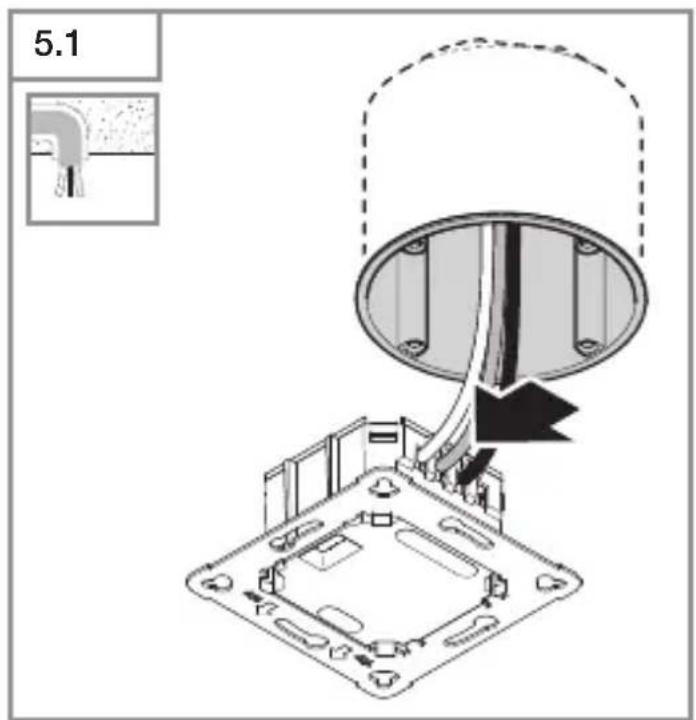
text_image
5.1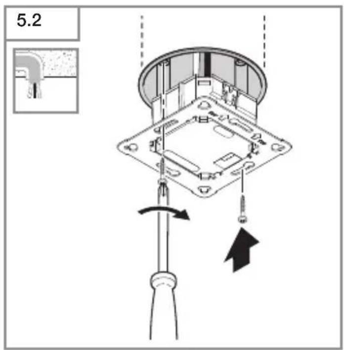
text_image
5.2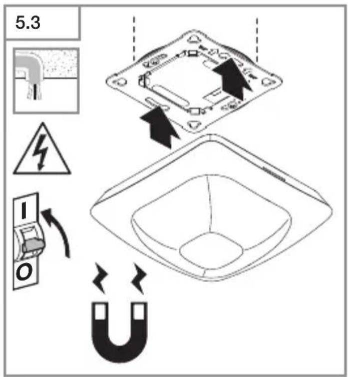
text_image
5.3 I O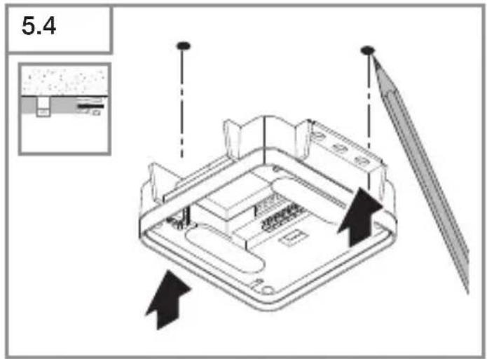
text_image
5.4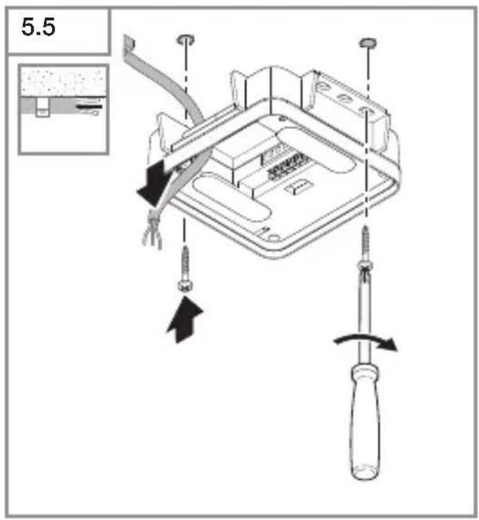
text_image
5.5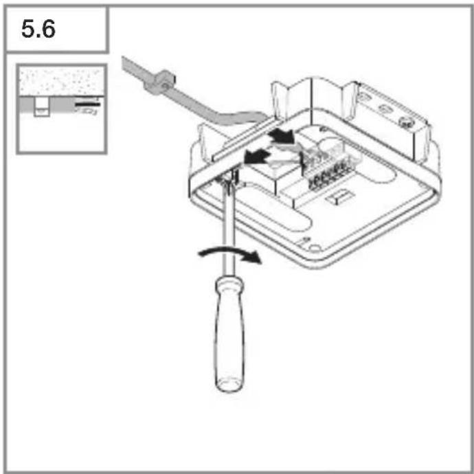
text_image
5.6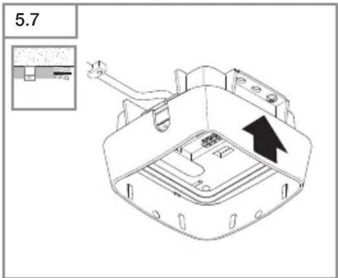
text_image
5.7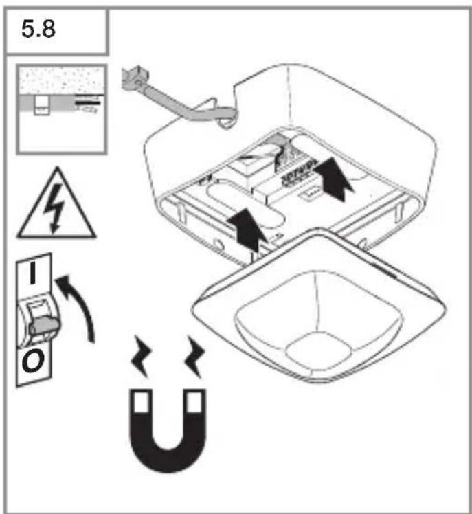
text_image
5.8 I O| 6.1 | IR Quattro HD | |||
| Montagehöhe /Mounting height | Poti Presence Radial Tangential | |||
| 2.50 m 1 | 3.0 m x 3.0 m 2.4 m x 2.4 m 3.8 m x 3.8 m | |||
| 2 | 3.0 m x 3.0 m 2.5 m x 2.5 m 4.0 m x 4.0 m | |||
| 3 | 4.0 m x 4.0 m 3.2 m x 3.2 m 6.0 m x 6.0 m | |||
| 4 | 5.0 m x 5.0 m 4.0 m x 4.0 m 16.0 m x 16.0 m | |||
| 5 | 7.0 m x 7.0 m 5.5 m x 5.5 m 16.5 m x 16.5 m | |||
| 6 | 8.0 m x 8.0 m 6.5 m x 6.5 m 21.5 m x 21.5 m | |||
| 7 | 9.0 m x 9.0 m 7.0 m x 7.0 m 22.0 m x 22.0 m | |||
| 2.80 m 1 | 3.0 m x 3.0 m 2.8 m x 2.8 m 4.4 m x 4.4 m | |||
| 2 | 3.0 m x 3.0 m 2.8 m x 2.8 m 4.4 m x 4.4 m | |||
| 3 | 4.0 m x 4.0 m 3.0 m x 3.0 m 5.0 m x 5.0 m | |||
| 4 | 6.0 m x 6.0 m 5.0 m x 5.0 m 8.4 m x 8.4 m | |||
| 5 | 8.0 m x 8.0 m 6.5 m x 6.5 m 17.0 m x 17.0 m | |||
| 6 | 8.0 m x 8.0 m 7.0 m x 7.0 m 22.0 m x 22.0 m | |||
| 7 | 9.0 m x 9.0 m 7.5 m x 7.5 m 24.0 m x 24.0 m | |||
| 3.00 m 1 | 4.0 m x 4.0 m 3.0 m x 3.0 m 4.5 m x 4.5 m | |||
| 2 | 4.0 m x 4.0 m 3.0 m x 3.0 m 4.5 m x 4.5 m | |||
| 3 | 5.0 m x 5.0 m 3.8 m x 3.8 m 5.5 m x 5.5 m | |||
| 4 | 5.0 m x 5.0 m 5.2 m x 5.2 m 9.0 m x 9.0 m | |||
| 5 | 7.0 m x 7.0 m 6.2 m x 6.2 m 14.5 m x 14.5 m | |||
| 6 | 8.0 m x 8.0 m 7.0 m x 7.0 m 23.0 m x 23.0 m | |||
| 7 | 8.0 m x 8.0 m 7.5 m x 7.5 m 24.0 m x 24.0 m | |||
| 3.50 m 1 | N/A 3.4 m x 3.4 m 4.4 m x 4.4 m | |||
| 2 | N/A 4.2 m x 4.2 m 4.8 m x 4.8 m | |||
| 3 | N/A 4.5 m x 4.5 m 6.4 m x 6.4 m | |||
| 4 | N/A 6.0 m x 6.0 m 9.5 m x 9.5 m | |||
| 5 | N/A 7.1 m x 7.1 m 17.0 m x 17.0 m | |||
| 6 | N/A 7.2 m x 7.2 m 24.0 m x 24.0 m | |||
| 7 | N/A 7.6 m x 7.6 m 26.0 m x 26.0 m | |||
| 4.00 m 1 | N/A 4.0 m x 4.0 m 5.0 m x 5.0 m | |||
| 2 | N/A 5.4 m x 5.4 m 6.0 m x 6.0 m | |||
| 3 | N/A 5.8 m x 5.8 m 8.0 m x 8.0 m | |||
| 4 | N/A 7.0 m x 7.0 m 12.0 m x 12.0 m | |||
| 5 | N/A 8.0 m x 8.0 m 20.0 m x 20.0 m | |||
| 6 | N/A 8.0 m x 8.0 m 26.5 m x 26.5 m | |||
| 7 | N/A 8.0 m x 8.0 m 30.0 m x 30.0 m | |||
| 5.00 m 1 | N/A 5.5 m x 5.5 m 7.2 m x 7.2 m | |||
| 2 | N/A 5.5 m x 5.5 m 7.2 m x 7.2 m | |||
| 3 | N/A 6.4 m x 6.4 m 8.8 m x 8.8 m | |||
| 4 | N/A 8.0 m x 8.0 m 12.0 m x 12.0 m | |||
| 5 | N/A 8.0 m x 8.0 m 23.0 m x 23.0 m | |||
| 6 | N/A 8.4 m x 8.4 m 30.4 m x 30.4 m | |||
| 7 | N/A 8.4 m x 8.4 m 35.0 m x 35.0 m | |||
| 6.00 m 1 | N/A 6.5 m x 6.5 m 8.5 m x 8.5 m | |||
| 2 | N/A 6.5 m x 6.5 m 9.0 m x 9.0 m | |||
| 3 | N/A 8.0 m x 8.0 m 13.0 m x 13.0 m | |||
| 4 | N/A 9.0 m x 9.0 m 18.0 m x 18.0 m | |||
| 5 | N/A 10.0 m x 10.0 m 29.0 m x 29.0 m | |||
| 6 | N/A 10.0 m x 10.0 m 30.0 m x 30.0 m | |||
| 7 | N/A 10.5 m x 10.5 m 30.0 m x 30.0 m | |||
| 8.00 m 1 | N/A 9.0 m x 9.0 m 12.8 m x 12.8 m | |||
| 2 | N/A 9.0 m x 9.0 m 12.8 m x 12.8 m | |||
| 3 | N/A 10.0 m x 10.0 m 14.0 m x 14.0 m | |||
| 4 | N/A 12.0 m x 12.0 m 23.0 m x 23.0 m | |||
| 5 | N/A 12.0 m x 12.0 m 30.0 m x 30.0 m | |||
| 6 | N/A 12.0 m x 12.0 m 32.0 m x 32.0 m | |||
| 7 | N/A 12.0 m x 12.0 m 34.0 m x 34.0 m | |||
| 10.00 m 1 | N/A 11.0 m x 11.0 m 15.5 m x 15.5 m | |||
| 2 | N/A 11.0 m x 11.0 m 15.5 m x 15.5 m | |||
| 3 | N/A 11.5 m x 11.5 m 19.5 m x 19.5 m | |||
| 4 | N/A 12.0 m x 12.0 m 26.0 m x 26.0 m | |||
| 5 | N/A 12.5 m x 12.5 m 32.5 m x 32.5 m | |||
| 6 | N/A 12.5 m x 12.5 m 34.0 m x 34.0 m | |||
| 7 | N/A 12.5 m x 12.5 m 35.5 m x 35.5 m | |||
DE
1. Zu diesem Dokument
- Bitte sorgfältig lesen und aufbewahren!
– Urheberrechtlichgeschützt.
Nachdruck, auch auszugsweise, nur mit unserer Genehmigung.
- Änderungen, die dem technischen
Fortschritt dienen, vorbehalten.
Symbolerklärung

Warnung vor Gefahren!

Verweis auf Textstellen im Dokument.
2. Allgemeine Sicherheitshinweise

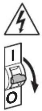
Vor allen Arbeiten am Sensor die Spannungszufuhr unterbrechen!
- Bei der Montage muss die anzu-schließende elektrische Leitung span-nungsfrei sein. Daher als Erstes Strom abschalten und Spannungsfreiheit mit einem Spannungsprüfer überprüfen.
- Bei der Installation des Sensors handelt es sich um eine Arbeit an der Netzspannung. Sie muss daher fachgerecht nach den landesüblichen Installationsvorschriften und Anschlussbedingungen durchgeführt werden.
- Nur Original-Ersatzteile verwenden.
- Reparaturen dürfen nur durch Fachwerkstätten durchgeführt werden.
- Der Anschluss B1/B0 ist ein Schaltkontakt für Niedrigenergieschaltkreise, nicht größer als 1 A. Dieser muss entsprechend abgesichert sein.
3. IR Quattro HD-2 COM1/COM2/BT IPD
Bestimmungsgemäßer Gebrauch
– Bewegungssensor zur Deckenmon tage im Innenbereich.
Der IR Quattro HD-2 zeichnet sich durch eine hochaufgelöste, hochempfindliche Bewegungserfassung aus. Der quadratische Erfassungsbereich kann exakt eingestellt werden. Der Sensor eignet sich insbesondere für Büroräume, Klassenräume aber auch große Industrieräume.
Schnittstellenvarianten
COM1: Relais 1
COM2: Relais 1 und Relais 2 (für HLK: Heizung/Lüftung/Klima)
BT IPD: Kein Relais/keine Steuerung
Die COM1- und COM2-Varianten schalten Lasten. Signal werden verarbeitet und ausgegeben.
Die BT IPD-Variante kann über Bluetooth mit anderen Sensoren vernetzt werden, um eine Erweiterung des Erfassungs-bereichs umzusetzen. Sie leitet die erfassten Signale (Präsenz und Helligkeit) über Bluetooth weiter. Die Steuerung erfolgt im vernetzten Sensor mit anderer Schnittstelle.
UP: Variante Unterputz
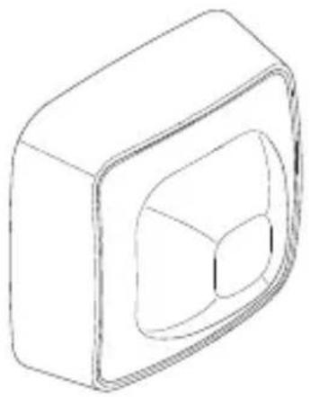
AP: Variante Aufputz
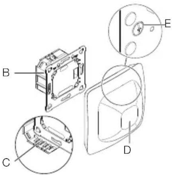
Lieferumfang (Abb. 3.1, Abb. 3.4)
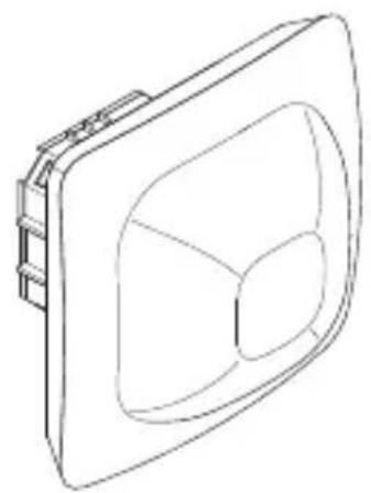
Produktmaße (Abb. 3.2, Abb. 3.5)
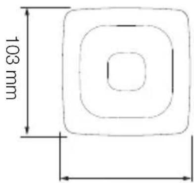
Geräteübersicht (Abb. 3.3, Abb. 3.6)
A Aufputzrahmen
B Lastmodul
C Anschlussklemme
D Sensormodul
E Reichweiteneinstellung
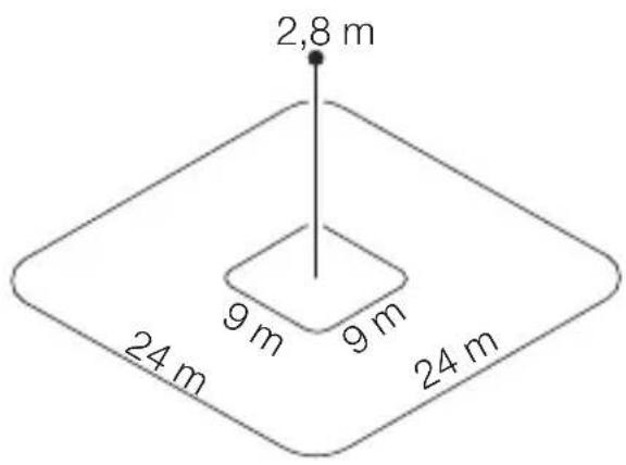
Erfassungsbereich (Abb. 3.7)
4. Elektrischer Anschluss
Die Netzzuleitung besteht aus einem mehradrigen Kabel (max. ∅ der Leitungen: 2,5 mm):
L = Phase (meistens schwarz oder braun)
N = Neutralleiter (meistens blau)
PE = Schutzleiter (meistens grün/gelb)
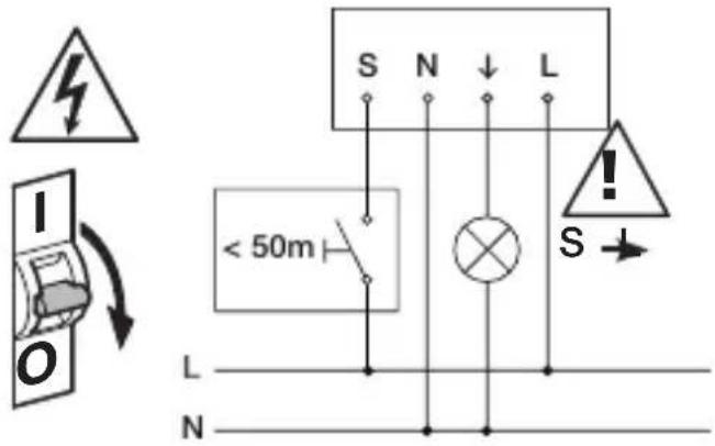
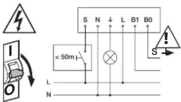
↓ = Geschaltete Phase (meistens schwarz, braun oder grau) S = Taster
B0/B1 = Potentialfreies Relais für HLK-Steuerung
Leitungslänge zwischen Sensor und Taster < 50 m.
Wichtig: Ein Vertauschen der Anschlüsse führt im Gerät oder Sicherungskasten später zum Kurzschluss. In diesem Fall müssen die einzelnen Kabel identifiziert und neu montiert werden.
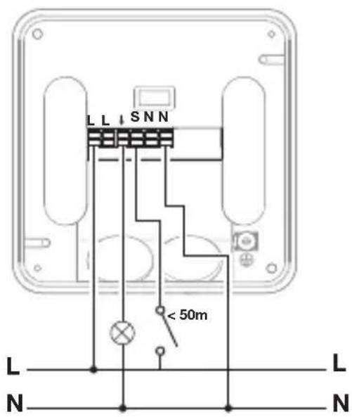
Anschluss Netzzuleitung COM1
(Abb. 4.1/4.4/4.7)
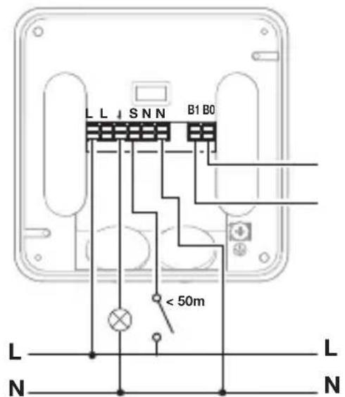
Anschluss Netzzuleitung COM2
(Abb. 4.2/4.5/4.8)
Anschluss Netzzuleitung BT IPD
(Abb. 4.3/4.6/4.9)
5. Montage
- Alle Bauteile auf Beschädigungen prüfen.
- Bei Schäden das Produkt nicht in Betrieb nehmen.
- Geeigneten Montageort auswählen unter Berücksichtigung der Reichweite und Anwesenheitserfassung. (Abb. 3.7)
Montageschritte
- Stromversorgung abstellen. (Abb. 4.1/4.2/4.3)
Montage Unterputz
- Netzanschluss vornehmen. (Abb. 5.1)
- Lastmodul einsetzen und festschrauben. (Abb. 5.2)
- Magnetisches Sensormodul aufsetzen. (Abb. 5.3)
- Stromversorgung einschalten. (Abb. 5.3)
Montage Aufputz
- Bohrlöcher einzeichnen und bohren. (Abb. 5.4)
- Lastmodul festschrauben. (Abb. 5.5)
- Netzanschluss vornehmen. (Abb. 5.6)
• Aufputzrahmen aufsetzen. (Abb. 5.7) - Magnetisches Sensormodul aufsetzen. (Abb. 5.8)
- Stromversorgung einschalten. (Abb. 5.8)
- Einstellungen vornehmen. (→ „6. Funktion und Einstellungen“)
6. Funktion und Einstellungen
Werkseinstellungen
Bei erstmaliger Inbetriebnahme des Präsenzmelders sowie beim Reset durch die App werden die Werkseinstellungen aktiviert.
Folgende Werkseinstellungen sind vorgesehen:
Sensitivität: Sensitivität A: 100 %
Sensitivität B: 100 %
Sensitivität C: 100 %
Sensitivität D: 100 %
Nur COM1/COM2:
Dämmerungseinstellung: 500 Lux
Zeiteinstellung COM1: 5 min
Zeiteinstellung HLK: 15 min
Voll-/Halbautomatik: Vollautomatik
Einschaltverzögerungen HLK: aus
Einstellung Erfassung
Der Erfassungsbereich kann über das
Poti (E) auf der Rückseite des Sensormoduls entsprechend der Tabelle eingestellt werden. (Abb. 3.7/6.1)
Die Sensitivität der vier Pyros (A bis D) kann über die APP eingestellt werden.
Gruppierung Bluetooth
Die Sensoren können als Einzelsensor oder als Gruppe betrieben werden. Die Gruppe wird über eine Funkkommunikation zusammengeschaltet.
Zusätzlich gelten für die Varianten COM1 und COM2 die nachfolgenden Funktionen:
Dämmerungseinstellung
Die gewünschte Ansprechschwelle kann von ca. 2 bis 2.000 Lux eingestellt werden.
Tagbetrieb
Der Sensor schaltet die Last unabhängig von der Umgebungshelligkeit, wenn Bewegung detektiert wird.
Teach-IN
Bei gewünschten Lichtverhältnissen, an denen der Sensor zukünftig bei Bewegung einschalten soll, wird die Teach-IN-Funktion gewählt. Nach 10 Sekunden wird der so gemessene Wert der Umgebungshelligkeit gespeichert. Gleichzeitig wird die Last abgeschaltet.
Zeiteinstellung
Die gewünschte Nachlaufzeit kann von min. 5 Sekunden bis max. 60 Minuten eingestellt werden. Wird keine Bewegung erkannt, schaltet der Sensor nach Ablauf der Nachlaufzeit aus.
Nachbarfunktion
Über die Steinel Connect App kann die Nachbarfunktion aktiviert bzw. deaktiviert werden. Dabei werden die Nachbargruppen der aktiven Sensorgruppe zugeordnet. Die Gruppe hört auf Einschaltsignale der zugeordneten Nachbargruppe und schaltet entsprechend der Einstellungen das Licht ein.
Betriebsart
Halbautomatik
Die Beleuchtung schaltet nur noch automatisch aus. Das Einschalten erfolgt manuell, Licht muss mit dem Taster angefordert werden und bleibt für die eingestellte Nachlaufzeit eingeschaltet.
Vollautomatik
Die Beleuchtung schaltet je nach Helligkeit und Präsenz automatisch EIN und AUS. Die Beleuchtung kann jederzeit manuell geschaltet werden. Dabei wird die Schaltautomatik vorübergehend unterbrochen.
Präsentationsmodus
Wird das Licht über einen Taster ausgeschaltet, aktiviert der Sensor den Präsentationsmodus. Die Last bleibt so lange ausgeschaltet, wie Bewegung detektiert wird. Sobald keine Bewegung mehr detektiert wird und die Nachlaufzeit abgelaufen ist, wechselt der Sensor wieder in den normalen Sensorbetrieb.
Taster Eingang
Über die STEINEL Connect App können Taster eingebunden und konfiguriert werden. Zusätzlich zum Eingang S können dem Sensor weitere Taster aus dem BT Mesh Netzwerk zugeordnet werden. Außerdem kann jedem dieser Taster eine Funktion zugewiesen werden. Ein Taster mit der Funktion "On / Off" kann die Beleuchtung manuell ein und ausschalten. Mit der Funktion "On" ist manuelles Ausschalten nicht mehr möglich. Dann wird bei jedem Tastendruck die Nachlaufzeit neu gestartet. Mit der Funktion "Off" kann die Beleuchtung nur manuell ausgeschaltet werden. Darüber hinaus gibt es die Funktionen "On x Min" und "Off x Min", mit denen die Beleuchtung für eine definierte Zeit ein- bzw. ausgeschaltet werden kann. Ein Taster ist zudem die Voraussetzung dafür, den Sensor im Halbautomatik-Modus zu betreiben.
Impulsmodus
Mit der Impulsfunktion wird der Ausgang für 2 Sekunden eingeschaltet (z. B. für einen Treppenhausautomaten). Anschließend befindet sich der Sensor in einer 8-sekündigen Totzeit.
Steinel Connect App
Für das Auslesen des Sensors mit Smartphone oder Tablet muss die STEINEL Connect App aus Ihrem AppStore heruntergeladen werden. Es ist ein Bluetooth-fähiges Smartphone oder Tablet erforderlich.
Android

text_image
QR code image containing encoded data, no visible human-readable textiOS

text_image
QR code image containing encoded data, no visible human-readable textBluetooth-Vernetzung (Bluetooth-Mesh)
Der Sensor-Schalter entspricht dem Bluetooth-Mesh-Standard. Er kann mit allen Produkten die dem Bluetooth-Mesh-Standard entsprechen vernetzt werden. Die Konfiguration des Sensor-Schalters erfolgt per Steinel Connect App. Bei der ersten Verbindung zwischen Sensor-Schalter und Steinel Connect App werden auf dem Smartphone oder Tablet entsprechende Netzwerkschlüssel gespeichert. Durch die Schlüssel ist ein unbefugter Zugriff auf den Sensor ausgeschlossen.
Für den Zugriff über ein weiteres Smartphone oder Tablet muss der Netzwerk-schlüssel geteilt werden.
LED-Funktion
Aufstarten: LED blinkt für 10 Sekunden langsam weiß
Initialisierung: LED leuchtet dauerhaft blau
Normalbetrieb: LED aus
Identifizierung: LED blinkt langsam blau
Fehler: LED blinkt schnell rot
Teach-IN erfolgreich beendet: LED
leuchtet für eine Sekunde grün
Keine Applikation vorhanden: LED
leuchtet dauerhaft cyan
Testbetrieb Bewegung:
LED blinkt schnell grün
Firmware Update: LED blinkt schnell cyan
7. Wartung und Pflege
Das Gerät ist wartungsfrei.
Gefahr durch elektrischen Strom!
Der Kontakt von Wasser mit stromführenden Teilen kann zu elektrischem Schock, Verbrennungen oder Tod führen.
- Gerät nur im trockenen Zustand reinigen.
Gefahr von Sachschäden!
Durch falsche Reinigungsmittel kann das Gerät beschädigt werden.
- Gerät mit einem leicht angefeuchteten Tuch ohne Reinigungsmittel reinigen.
8. Entsorgung
Elektrogeräte, Zubehör und Verpackungen sollen einer umweltgerechten Wiederverwertung zugeführt werden.
Werfen Sie Elektrogeräte nicht in den Hausmüll!
Nur für EU-Länder
Gemäß der geltenden Europäischen Richtlinie über Elektro- und Elektronik-Altgeräte und ihrer Umsetzung in nationales Recht müssen nicht mehr gebrauchsfähige Elektrogeräte getrennt gesammelt und einer umweltgerechten Wiederverwertung zugeführt werden.
9. Konformität
Hiermit erklärt die STEINEL Vertrieb GmbH, dass der Funkanlagentyp IR Quattro HD-2 COM1/COM2/BT IPD der Richtlinie 2014/53/EU entspricht. Der vollständige Text der EU-Konformitätserklärung ist unter der folgenden Internet-adresse verfügbar: www.steinel.de
10. Herstellergarantie
Herstellergarantie für Unternehmer, wobei Unternehmer eine natürliche oder juristische Person oder eine rechtsfähige Personengesellschaft ist, die bei Abschluss des Kaufes in Ausübung ihrer gewerblichen oder selbständigen beruflichen Tätigkeit handelt.
Herstellergarantie der STEINEL Vertrieb GmbH, Dieselstraße 80-84, 33442 Herzebrock-Clarholz
Alle STEINEL-Produkte erfüllen höchste Qualitätsansprüche. Aus diesem Grund leisten wir als Hersteller Ihnen als Kunde gerne eine unentgeltliche Garantie gemäß den nachstehenden Bedingungen:
Wir leisten Garantie durch kostenlose Behebung der Mängel (nach unserer Wahl: Reparatur oder Austausch mangelhafter Teile ggf. Austausch durch ein Nachfolgemodell oder Erstellung einer Gutschrift), die nachweislich innerhalb der Garantiezeit auf einem Material- oder Herstellungsfehler beruhen.
Die Garantiezeit für
- Sensorik / Außenleuchten / Innen-leuchten beträgt: 5 Jahre und beginnt mit dem Kaufdatum des Produktes.
Ausdrücklich ausgenommen von dieser Garantie sind alle auswechselbaren Leuchtmittel. Darüber hinaus ist die Garantie ausgeschlossen:
- bei einem gebrauchsbedingten oder sonstigen natürlichen Verschleiß von Produktteilen oder Mängeln am STEINEL-Produkt, die auf gebrauchsbedingtem oder sonstigem natürlichem Verschleiß zurückzuführen sind,
- bei nicht bestimmungs- oder unsachgemäßem Gebrauch des Produkts oder Missachtung der Bedienungs-hinweise,
- wenn An- und Umbauten bzw. sonstige Modifikationen an dem Produkt eigenmächtig vorgenommen wurden oder Mängel auf die Verwendung von Zubehör-, Ergänzungs- oder Ersatzteilen zurückzuführen sind, die keine STEINEL-Originalteile sind,
- wenn Wartung und Pflege der Produkte nicht entsprechend der Bedienungsanleitung erfolgt sind,
- wenn Anbau und Installation nicht gemäß den Installationsvorschriften von STEINEL ausgeführt wurden,
- bei Transportschäden oder -verlusten.
Diese Herstellergarantie lässt Ihre gesetzlichen Rechte unberührt. Die hier beschriebenen Leistungen gelten zusätzlich zu den gesetzlichen Rechten und beschränken oder ersetzen diese nicht.
Die Garantie gilt für sämtliche STEINEL-Produkte, die in Deutschland gekauft und verwendet werden. Es gilt deutsches Recht unter Ausschluss des Übereinkommens der Vereinten Nationen über Verträge über den internationalen Warenkauf (CISG).
Geltendmachung
Wenn Sie Ihr Produkt reklamieren wollen, senden Sie es bitte vollständig und frachtfrei mit dem Original-Kaufbeleg, der die Angabe des Kaufdatums und der Produktbezeichnung enthalten muss, an Ihren Händler oder direkt an uns, die STEINEL Vertrieb GmbH – Reklamationsabteilung –, Dieselstraße 80-84, 33442 Herzebrock-Clarholz.
Wir empfehlen Ihnen daher, Ihren Kaufbeleg bis zum Ablauf der Garantiezeit sorgfältig aufzubewahren. Für Transportkosten und -risiken im Rahmen der Rücksendung übernehmen wir keine Haftung.
5 JAHRE HERSTELLER GARANTIE
- Technische Daten
| Abmessungen(L × H × T in mm) | IR-Quattro HD UP: 103 × 103 × 69IR-Quattro HD AP: 123 × 123 × 64 |
| Eingangsspannung 220-240 V, 50/60 Hz | |
| Leistungsaufnahme• Stand-by < 0,5 W | |
| Leistung Schaltausgang 1:(COM 1/COM 2) | Glüh-/ Halogenlampenlast 2.000 WLeuchtstofflampen EVG 1.500 WLeuchtstofflampen unkompensiert 1.000 VALeuchtstofflampen reihenkompensiert 400 VALeuchtstofflampen parallelkompensiert 1.000 VANiedervolt Halogenlampen 2.000 VALED < 2 W 100 W2 W < LED < 8 W 300 WLED > 8 W 600 WKapazitive Belastung 176 μF |
| Leistung Schaltausgang 2:(nur COM 2) | AC: Max. 1A @ 230VAC / 240W (cos phi = 1)Min 0,08mA @ 230VACDC: Max 2A @ 24VMin 10mA @ 5V, 50mW |
| Zeiteinstellung | 10 s bis 60 Minuten |
| Dämmerungseinstellung | 2-2.000 Lux |
| Reichweite | Präsenz 9 × 9 mmax. 24 × 24 m |
| Erfassungswinkel | 360° |
| Montagehöhe | 2,5-10 m |
| Schutzart | IP54 (nur Aufputzvariante) |
| Temperaturbereich | -20 °C bis +50 °C |
| Frequenz Bluetooth | 2,4-2,48 GHz |
| Sendeleistung Bluetooth | 5 dBm/3 mW |
12. Betriebsstörungen
Störung Ursache Abhilfe
| Licht schaltet nicht ein■ keine Anschluss-spannung■ Lux-Wert zu niedrig eingestellt■ keine Bewegungs-erfassung | ■ Anschlussspannung überprüfen■ Lux-Wert langsam erhöhen bis Licht einschaltet■ Freie Sicht auf den Sensor herstellen■ Erfassungsbereich überprüfen |
| Licht schaltet nicht aus■ Lux-Wert zu hoch■ Nachlaufzeit läuft ab■ Störende Wärmequellen z. B.: Heizlüfter, offene Türen und Fenster, Haustiere, Glühbirne/Halogenstrahler, sich bewegende Objekte | ■ Lux-Wert niedriger stellen■ Nachlaufzeit abwarten ggf. Nachlaufzeit kleiner stellen■ Erfassungsbereich überprüfen |
| Sensor schaltet trotz Anwesenheit ab■ Nachlaufzeit zu klein■ Lichtschwelle zu niedrig | ■ Nachlaufzeit erhöhen■ Dämmerungseinstellung ändern |
| Sensor schaltet zu spät ab■ Nachlaufzeit zu groß | ■ Nachlaufzeit verkleinern |
| Sensor schaltet bei frontaler Gehrichtung zu spät ein■ Reichweite bei frontaler Gehrichtung ist reduziert | ■ weitere Sensoren montieren■ Abstand zwischen zwei Sensoren reduzieren |
| Sensor schaltet trotz Dunkelheit bei Anwesenheit nicht ein■ Lux-Wert zu niedrig gewählt■ Halbautomatik aktiv■ 4 Stunden AUS aktiv | ■ Helligkeitsschwelle erhöhen■ Vollautomatik aktivieren oder Licht über Taster einschalten■ 4 Stunden AUS deaktivieren |
| Sensor verbindet sich nicht mit der App■ Systemabsturz der App oder des Smartphones | ■ Mobiles Endgerät neu starten |
GB
1. About this document
- Please read carefully and keep in a safe place.
- Undercopyright.
Reproduction either in whole or in part only with our consent. - Subject to change in the interest of technical progress.
Symbols

Hazard warning!

Reference to other information in the document.
2. General safety precautions

Disconnect the power supply before attempting any work on the sensor.
- During installation, the electric power cable being connected must not be live. Therefore, switch off the power first and use a voltage tester to make sure the wiring is off-circuit.
- Installing the sensor involves work on the mains power supply. This work must therefore be carried out professionally in accordance with national wiring regulations and electrical operating conditions.
- Only use genuine replacement parts.
- Repairs may only be made by specialist workshops.
- Terminal B1/B0 is a switching contact for low-energy circuits, no more than 1 A. This must be protected by a fuse of the appropriate rating.
3. IR Quattro HD-2 COM1/COM2/BT IPD
Proper use
- Motion sensor for ceiling mounting indoors.
The IR Quattro HD-2 provides high-resolution, highly sensitive motion detection. The square detection zone can be set with absolute precision. The sensor is particularly suitable for offices, classrooms and large industrial spaces.
Interface types
COM1: relay 1
COM2: relay 1 and relay 2 (for HVAC: heating/ventilation/air-conditioning)
BT IPD: no relay/no control
The COM1 and COM2 versions switch loads ON and OFF. Signals are processed and sent out.
The BT IPD version can be interconnected with other sensors via Bluetooth to extend the detection zone. It passes on the detected signals (presence and light level) via Bluetooth. This is controlled in the sensor interconnected with other interface.
UP: concealed version
AP: surface-mounted version
Package contents (Fig. 3.1, Fig. 3.4)
Product dimensions (Fig. 3.2, Fig. 3.5)
Product components (Fig. 3.3, Fig. 3.6)
A Surface-mounted surround
B Load module
C Connecting terminal
D Sensor module
E Reach adjustment
Detection zone (Fig. 3.7)
4. Electrical connection
The mains supply lead is a multiple-core cable (max. conductor ∅ 2.5 mm):
L = Phase conductor (usually black or brown)
N = Neutral conductor (usually blue)
PE=Protective-earthconductor (usually green/yellow)
↓ = Switched phase conductor (usually black, brown or grey)
S = Switch
B0/B1 = Floating relay for controlling HVAC
Cable length between sensor and button < 50 m.
Important: Incorrectly wired connections will produce a short circuit later on in the product or fuse box. In this case, you must identify the individual cables and re-connect them.
Connect the mains power supply lead COM1 (Fig. 4.1/4.4/4.7)
Connect the mains power supply lead COM2 (Fig. 4.2/4.5/4.8)
Connect the mains power supply lead BT IPD (Fig. 4.3/4.6/4.9)
5. Installation
- Check all components for damage.
- Do not use the product if it is damaged.
- Select an appropriate mounting location, taking the reach and presence detection into consideration (Fig. 3.7)
Mounting procedure
- Switch off power supply. (Fig. 4.1/4.2/4.3)
Concealed mounting
- Connect to mains power supply. (Fig. 5.1)
- Fit load module and screw into place. (Fig. 5.2)
• Fit magnetic sensor module. (Fig. 5.3) - Switch ON power supply. (Fig. 5.3)
Surface mounting
• Mark drill holes and drill. (Fig. 5.4)
- Screw load module into place. (Fig. 5.5)
- Connect to mains power supply. (Fig. 5.6)
• Fit surface-mounted surround. (Fig. 5.7)
• Fit magnetic sensor module. (Fig. 5.8)
- Switch ON power supply. (Fig. 5.8)
- Make settings.
(→ „6. Function and settings“)
6. Function and settings
Factory settings
The factory settings are activated when the presence detector is put into operation for the first time as well as after resetting by the app.
The following factory settings are provided:
Sensitivity: Sensitivity A: 100%
Sensitivity B: 100%
Sensitivity C: 100%
Sensitivity D: 100%
COM1/COM2 only:
Twilight level: 500 lux
Time setting for COM1: 5 min
Time setting for HVAC: 15 min
Fully/semi-automatic mode:
fully automatic
Switch-ON delays for HVAC: OFF
Setting detection
The detection zone can be also set via the potentiometer (E) on the back of the sensor module in accordance with the table. (Fig. 3.7/6.1)
The sensitivity of the four pyros (A to D) can be set via the app.
Bluetooth grouping
The sensors can be operated as individual sensors or as a group. The group is interconnected via wireless communication.
The COM1 and COM2 versions additionally provide the following functions:
Twilight setting
The chosen response threshold can be set from approx. 2 to 2,000 lux.
Daytime operation
When movement is detected, the sensor switches the load ON irrespective of ambient brightness.
Teach-IN
The Teach-IN function is to be selected at the level of light at which you want the sensor to respond to movement from now on. The level of ambient brightness measured in this way will be saved after 10 seconds. The load is deactivated during this period.
Time setting
The chosen stay-ON time can be set from a minimum of 5 seconds to a maximum of 60 minutes. If no movement is detected, the sensor switches OFF after the stay-ON time expires.
Neighbouring-light function
The neighbouring-light function can be activated and deactivated via the Steinel Connect app. This function assigns the neighbouring groups to the active sensor group. The group responds to activation signals from the neighbouring group assigned to it and switches the light ON as defined in the settings.
Operating mode
Semi-automatic mode
The light now only switches OFF automatically. Light is switched ON manually. Light must be requested using the button and stays ON for the time set.
Fully automatic mode
The light automatically switches ON and OFF in relation to light level when someone is present. Light can be switched ON and OFF manually at any time.
This temporarily interrupts the automatic switching function.
Presentation mode
If light is switched OFF via a push-button, the sensor activates the presentation mode. The load remains switched OFF as long as movement is being detected. As soon as movement is no longer being detected and the stay-ON time has elapsed, the sensor returns to normal sensor mode.
Button input
Push-buttons can be integrated and configured via the STEINEL Connect app. In addition to input S, further push-buttons can be assigned to the sensor from the BT Mesh network. A function can also be assigned to each of these buttons. A pushbutton with the "ON / OFF" function provides the option of switching lighting ON and OFF by hand. However, the "ON" function cannot be used for switching light OFF again. In this case, the stay-ON time is re-started each time the button is pressed. The "OFF" function can only be used to switch lighting OFF manually. "ON x min" and "OFF x min" functions are also available that can be used for switching lighting ON or OFF for a defined period of time. A pushbutton is required for operating the sensor in semi-automatic mode.
Pulse mode
The pulse function activates the output for 2 seconds (E.g. for an automatic stair-case lighting time switch). The sensor will then be in a dead time for 8 seconds.
Steinel Connect App
To read off the sensor via smartphone or tablet, you must download the Steinel Connect app from your app store. You will need a Bluetooth-capable smart-phone or tablet.
Android

text_image
QR code image containing encoded data, no visible human-readable textiOS

text_image
QR code image containing encoded data, no visible human-readable textBluetooth interconnection (Bluetooth Mesh)
The sensor switch complies with the Bluetooth Mesh standard. It can be interconnected with all products complying with the Bluetooth Mesh standard. The sensor switch is configured via the Steinel Connect app. Appropriate network keys are saved on a smartphone or tablet the first time a connection is made between the sensor switch and Steinel Connect app. The key rules out any unauthorised access to the sensor.
The network key must be shared for access via another smartphone or tablet.
LED function
Starting up: The LED flashes white slowly for 10 seconds
Initialisation: The LED lights up blue permanently
Normal mode: LED OFF
Identification: The LED flashes blue slowly
Error: The LED flashes red rapidly
Teach-IN successfully completed:
The LED lights up green for one second
No application available: The lights up in cyan permanently
Movement test mode:
The LED flashes green rapidly
Firmware update: The LED flashes cyan rapidly
7. Maintenance and care
The tool requires no maintenance. Hazard from electrical power.
Contact between water and live parts can result in electric shock, burns or death.
- Only clean tool in a dry state.
Risk of damage to property!
Using the wrong cleaning product can damage the light.
- Clean tool with a moist cloth without detergent.
8. Disposal
Electrical and electronic equipment, accessories and packaging must be recycled in an environmentally compatible manner.

Do not dispose of electrical and electronic equipment as domestic waste.
EU countries only
Under the current European Directive on Waste Electrical and Electronic Equipment and its implementation in national law, electrical and electronic equipment no longer suitable for use must be collected separately and recycled in an environmentally compatible manner.
9. Conformity
STEINEL Vertrieb GmbH hereby declares that the IR Quattro HD-2 COM1/COM2/BT IPD radio equipment type conforms to Directive 2014/53/EU. The full wording of the EU Declaration of Conformity is available for downloading from the following Internet address: www.steinel.de
10. Manufacturer's Warranty
As purchaser, you are entitled to your statutory rights against the vendor. If these rights exist in your country, they are neither curtailed nor restricted by our Warranty Declaration. We guarantee that your STEINEL Professional sensor product will remain in perfect condition and proper working order for a period of 5 years. We guarantee that this product is free from material-, manufacturing- and design flaws. In addition, we guarantee that all electronic components and cables function in the proper manner and that all materials used and their surfaces are without defects.
Making Claims
If you wish to make a claim, please send your product complete and carriage paid with the original receipt of purchase, which must show the date of purchase and product designation, either to your retailer or contact us at STEINEL(UK) Limited, 25 Manasty Road, Axis Park, Orton Southgate, Peterborough, PE2 6UP, for a returns number. For this reason, we recommend that you keep your receipt of purchase in a safe place until the warranty period expires. STEINEL shall assume no liability for the costs or risks involved in returning a product.
For information on making claims under the terms of the warranty, please go to www.steinel-professional.de/garantie
If you have a warranty claim or would like to ask any question regarding your product, you are welcome to call us at any time on our Service Hotline 01733 366700.

- Technische Daten
| Dimensions(L × D × H in mm) | IR-Quattro HD UP: 103 × 103 × 69IR-Quattro HD AP: 123 × 123 × 64 |
| Input voltage 220-240 V, 50/60 Hz | |
| Power consumption• Stand-by < 0,5 W | |
| Capacity, switchingoutput 1: (COM 1/COM 2) | Incandescent/halogen lamp load 2,000 WFluorescent lamps, electronic ballast 1,500 WFluorescent lamps, uncorrected 1,000 VAFluorescent lamps, series-corrected 400 VAFluorescent lamps, parallel-corrected 1,000 VALow-voltage halogen lamps 2,000 VALED < 2 W 100 W2 W < LED < 8 W 300 WLED > 8 W 600 WCapacitive load 176 μF |
| Capacity, switchingoutput 2: (COM 2 only) | AC: max. 1 A @ 230 V AC / 240 W (cos phi = 1)min 0.08 mA @ 230 V ACDC: max 2 A @ 24 Vmin 10 mA @ 5 V, 50 mW |
| Time setting | 10 s to 60 min, |
| Twilight setting | 2-2,000 lux |
| Reach | Presence 9 × 9 mMax. 24 × 24 m |
| Angle of coverage | 360° |
| Mounting height | 2,5-10 m |
| IP rating | IP54 (surface-mounted version only) |
| Temperature range | -20°C to +50°C |
| Bluetooth frequency | 2,4-2,48 GHz |
| Bluetooth transmitter power | 5 dBm/3 mW |
12. Troubleshooting
Malfunction Cause Remedy
| Light does not switch ON ■ | No supply voltage■ Lux setting too low■ No movement detection | ■ Check supply voltage■ Slowly increase lux setting until light switches ON■ Ensure unobstructed sensor vision■ Check detection zone |
| Light does not switch OFF ■ | Lux setting too high■ Stay-ON time running out■ Interfering heat sources: e.g. fan heater, open doors and windows, pets, light bulb/halogen floodlight, moving objects | ■ Reduce lux setting■ Wait until stay-ON time elapses; reduce stay-ON time if necessary■ Check detection zone |
| Sensor switches OFF despite persons being present | ■ Stay-ON time too short■ Light-level threshold too low | ■ Increase stay-ON time■ Change twilight setting |
| Sensor does not switch OFF quickly enough | ■ Stay-ON time too long | ■ Reduce stay-ON time |
| Sensor does not switch ON quickly enough when approached from the front | ■ Reach is reduced when approached from the front | ■ Install additional sensors■ Reduce distance between two sensors |
| Sensor does not switch ON when persons are present despite it being dark | ■ Lux setting too low■ Semi-automatic mode activated■ 4 hours OFF activated | ■ Increase light-level threshold■ Activate fully automatic mode or switch light ON at button■ Deactivate 4 hours OFF |
| Sensor not connecting with the app | ■ App or smartphone system crash | ■ Restart mobile end device |
STEINEL Vertrieb GmbH
Dieselstraße 80-84
33442 Herzebrock-Clarholz
Tel: +49/5245/448-188
www.steinel.de

natural_image
World map silhouette in grayscale, showing continents and oceans without any text or labelsContact
www.steinel.de/contact