IR Quattro HD2 COM1 - Motion detector STEINEL - Free user manual and instructions
Find the device manual for free IR Quattro HD2 COM1 STEINEL in PDF.

User questions about IR Quattro HD2 COM1 STEINEL
0 question about this device. Answer the ones you know or ask your own.
Ask a new question about this device
Download the instructions for your Motion detector in PDF format for free! Find your manual IR Quattro HD2 COM1 - STEINEL and take your electronic device back in hand. On this page are published all the documents necessary for the use of your device. IR Quattro HD2 COM1 by STEINEL.
USER MANUAL IR Quattro HD2 COM1 STEINEL
natural_image
White rectangular electronic device with a circular button labeled 'TALWATS' (no additional text or symbols visible)IR Quattro HD-2 COM1/COM2/BT IPD

DE .... 9 Textteil beachten!
GB .... 17 Follow written instructions!
3.1 COM1/COM2/BT IPD UP
natural_image
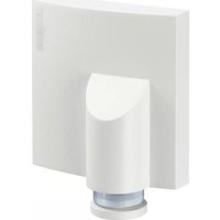
Isometric line drawing of a rectangular device with a central circular cutout (no text or symbols)3.2
text_image
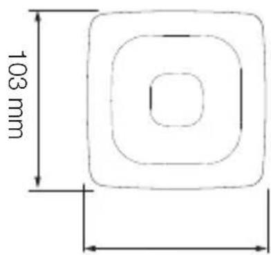
103 mm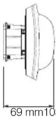
text_image
69 mm1033.3
text_image
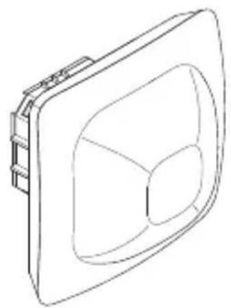
Technical diagram of a device with labeled components A, B, C, D, and E showing internal structure and detail views.3.4 COM1/COM2/BT IPD AP
natural_image
Isometric line drawing of a 3D rectangular block with a central cutout (no text or symbols)3.7
text_image
2,8 m 9 m 9 m 24 m 24 m3.5
text_image
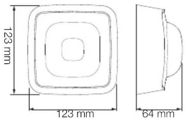
123 mm 123 mm 64 mm4.1 COM 1
text_image
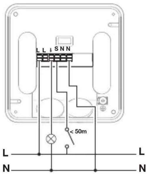
S N ↓ L < 50m L N S3.6
text_image
A B C D E4.2 COM 2
text_image
S N ↓ L B1 B0 < 50m L N4.3 BT IPD
text_image
Safety warning symbol and electrical circuit diagram showing lightning bolt, switch, and battery with current direction arrow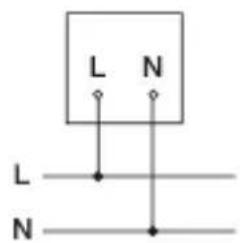
text_image
L N L N4.4 COM 1 AP
text_image
LL SNN < 50m L L N N4.5 COM 2 AP
text_image
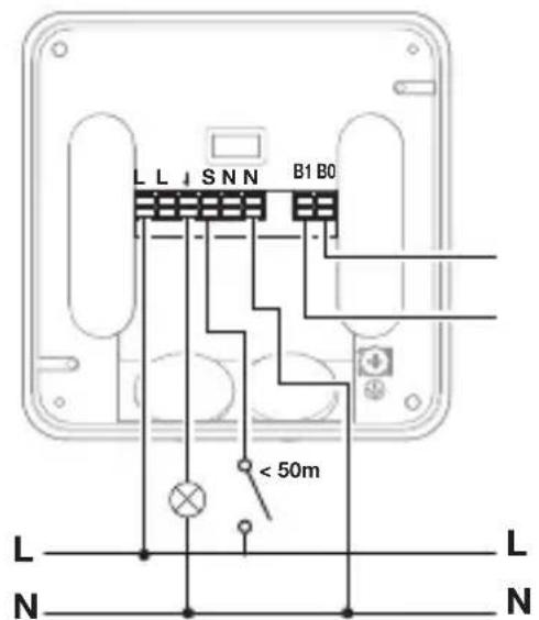
LL SNN B1 B0 < 50m L N L N4.6 BT IPD AP
text_image
L L N L N L N4.7 COM 1 UP
text_image
T N S L4.8 COM 2 UP
text_image
N S L ↓ B1B0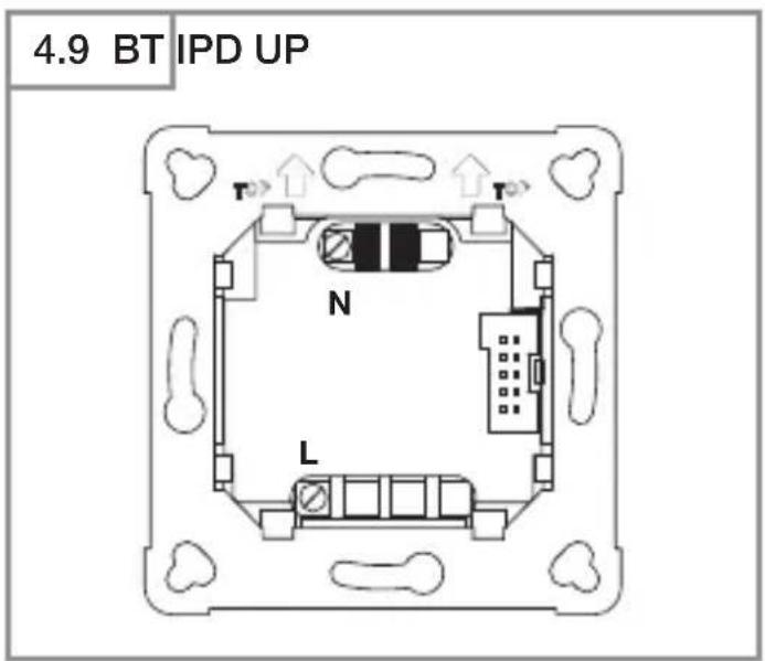
text_image
4.9 BT IPD UP T N L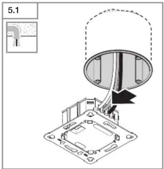
text_image
5.1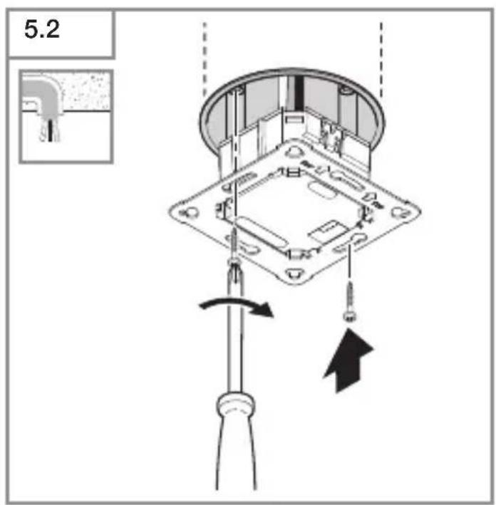
text_image
5.2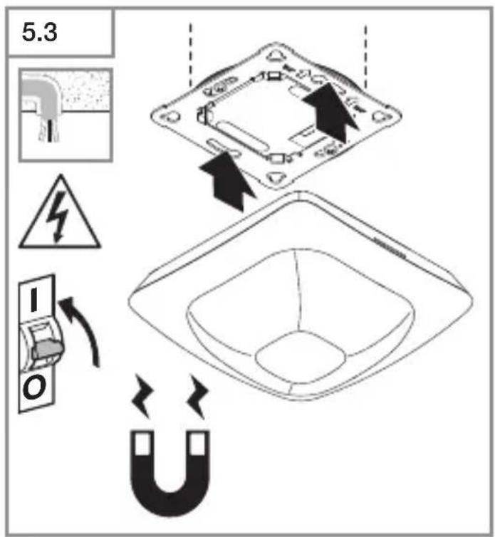
text_image
5.3 I O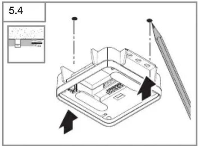
text_image
5.4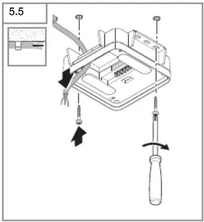
text_image
5.5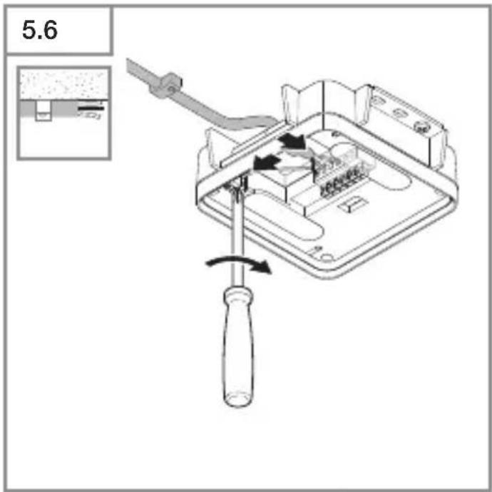
text_image
5.6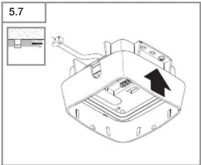
text_image
5.7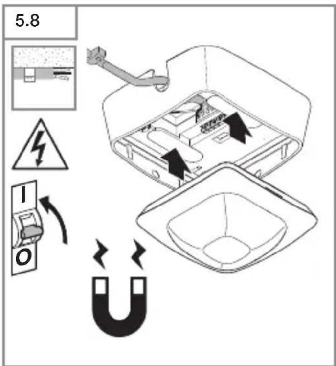
text_image
5.8 I O| 6.1 | IR Quattro HD | |||
| Montagehöhe /Mounting height | Poti Presence Radial Tangential | |||
| 2.50 m 1 | 3.0 m x 3.0 m 2.4 m x 2.4 m 3.8 m x 3.8 m | |||
| 2 | 3.0 m x 3.0 m 2.5 m x 2.5 m 4.0 m x 4.0 m | |||
| 3 | 4.0 m x 4.0 m 3.2 m x 3.2 m 6.0 m x 6.0 m | |||
| 4 | 5.0 m x 5.0 m 4.0 m x 4.0 m 16.0 m x 16.0 m | |||
| 5 | 7.0 m x 7.0 m 5.5 m x 5.5 m 16.5 m x 16.5 m | |||
| 6 | 8.0 m x 8.0 m 6.5 m x 6.5 m 21.5 m x 21.5 m | |||
| 7 | 9.0 m x 9.0 m 7.0 m x 7.0 m 22.0 m x 22.0 m | |||
| 2.80 m 1 | 3.0 m x 3.0 m 2.8 m x 2.8 m 4.4 m x 4.4 m | |||
| 2 | 3.0 m x 3.0 m 2.8 m x 2.8 m 4.4 m x 4.4 m | |||
| 3 | 4.0 m x 4.0 m 3.0 m x 3.0 m 5.0 m x 5.0 m | |||
| 4 | 6.0 m x 6.0 m 5.0 m x 5.0 m 8.4 m x 8.4 m | |||
| 5 | 8.0 m x 8.0 m 6.5 m x 6.5 m 17.0 m x 17.0 m | |||
| 6 | 8.0 m x 8.0 m 7.0 m x 7.0 m 22.0 m x 22.0 m | |||
| 7 | 9.0 m x 9.0 m 7.5 m x 7.5 m 24.0 m x 24.0 m | |||
| 3.00 m 1 | 4.0 m x 4.0 m 3.0 m x 3.0 m 4.5 m x 4.5 m | |||
| 2 | 4.0 m x 4.0 m 3.0 m x 3.0 m 4.5 m x 4.5 m | |||
| 3 | 5.0 m x 5.0 m 3.8 m x 3.8 m 5.5 m x 5.5 m | |||
| 4 | 5.0 m x 5.0 m 5.2 m x 5.2 m 9.0 m x 9.0 m | |||
| 5 | 7.0 m x 7.0 m 6.2 m x 6.2 m 14.5 m x 14.5 m | |||
| 6 | 8.0 m x 8.0 m 7.0 m x 7.0 m 23.0 m x 23.0 m | |||
| 7 | 8.0 m x 8.0 m 7.5 m x 7.5 m 24.0 m x 24.0 m | |||
| 3.50 m 1 | N/A 3.4 m x 3.4 m 4.4 m x 4.4 m | |||
| 2 | N/A 4.2 m x 4.2 m 4.8 m x 4.8 m | |||
| 3 | N/A 4.5 m x 4.5 m 6.4 m x 6.4 m | |||
| 4 | N/A 6.0 m x 6.0 m 9.5 m x 9.5 m | |||
| 5 | N/A 7.1 m x 7.1 m 17.0 m x 17.0 m | |||
| 6 | N/A 7.2 m x 7.2 m 24.0 m x 24.0 m | |||
| 7 | N/A 7.6 m x 7.6 m 26.0 m x 26.0 m | |||
| 4.00 m 1 | N/A 4.0 m x 4.0 m 5.0 m x 5.0 m | |||
| 2 | N/A 5.4 m x 5.4 m 6.0 m x 6.0 m | |||
| 3 | N/A 5.8 m x 5.8 m 8.0 m x 8.0 m | |||
| 4 | N/A 7.0 m x 7.0 m 12.0 m x 12.0 m | |||
| 5 | N/A 8.0 m x 8.0 m 20.0 m x 20.0 m | |||
| 6 | N/A 8.0 m x 8.0 m 26.5 m x 26.5 m | |||
| 7 | N/A 8.0 m x 8.0 m 30.0 m x 30.0 m | |||
| 5.00 m 1 | N/A 5.5 m x 5.5 m 7.2 m x 7.2 m | |||
| 2 | N/A 5.5 m x 5.5 m 7.2 m x 7.2 m | |||
| 3 | N/A 6.4 m x 6.4 m 8.8 m x 8.8 m | |||
| 4 | N/A 8.0 m x 8.0 m 12.0 m x 12.0 m | |||
| 5 | N/A 8.0 m x 8.0 m 23.0 m x 23.0 m | |||
| 6 | N/A 8.4 m x 8.4 m 30.4 m x 30.4 m | |||
| 7 | N/A 8.4 m x 8.4 m 35.0 m x 35.0 m | |||
| 6.00 m 1 | N/A 6.5 m x 6.5 m 8.5 m x 8.5 m | |||
| 2 | N/A 6.5 m x 6.5 m 9.0 m x 9.0 m | |||
| 3 | N/A 8.0 m x 8.0 m 13.0 m x 13.0 m | |||
| 4 | N/A 9.0 m x 9.0 m 18.0 m x 18.0 m | |||
| 5 | N/A 10.0 m x 10.0 m 29.0 m x 29.0 m | |||
| 6 | N/A 10.0 m x 10.0 m 30.0 m x 30.0 m | |||
| 7 | N/A 10.5 m x 10.5 m 30.0 m x 30.0 m | |||
| 8.00 m 1 | N/A 9.0 m x 9.0 m 12.8 m x 12.8 m | |||
| 2 | N/A 9.0 m x 9.0 m 12.8 m x 12.8 m | |||
| 3 | N/A 10.0 m x 10.0 m 14.0 m x 14.0 m | |||
| 4 | N/A 12.0 m x 12.0 m 23.0 m x 23.0 m | |||
| 5 | N/A 12.0 m x 12.0 m 30.0 m x 30.0 m | |||
| 6 | N/A 12.0 m x 12.0 m 32.0 m x 32.0 m | |||
| 7 | N/A 12.0 m x 12.0 m 34.0 m x 34.0 m | |||
| 10.00 m 1 | N/A 11.0 m x 11.0 m 15.5 m x 15.5 m | |||
| 2 | N/A 11.0 m x 11.0 m 15.5 m x 15.5 m | |||
| 3 | N/A 11.5 m x 11.5 m 19.5 m x 19.5 m | |||
| 4 | N/A 12.0 m x 12.0 m 26.0 m x 26.0 m | |||
| 5 | N/A 12.5 m x 12.5 m 32.5 m x 32.5 m | |||
| 6 | N/A 12.5 m x 12.5 m 34.0 m x 34.0 m | |||
| 7 | N/A 12.5 m x 12.5 m 35.5 m x 35.5 m | |||
DE
text_image
QR code image containing encoded data, no visible human-readable textiOS

text_image
QR code image containing encoded data, no visible human-readable text- Please read carefully and keep in a safe place.
- Undercopyright.
Reproduction either in whole or in part only with our consent. - Subject to change in the interest of technical progress.
Symbols

Hazard warning!

Reference to other information in the document.
2. General safety precautions

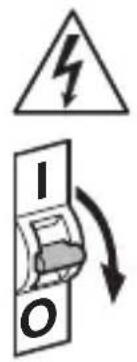
Disconnect the power supply before attempting any work on the sensor.
- During installation, the electric power cable being connected must not be live. Therefore, switch off the power first and use a voltage tester to make sure the wiring is off-circuit.
- Installing the sensor involves work on the mains power supply. This work must therefore be carried out professionally in accordance with national wiring regulations and electrical operating conditions.
- Only use genuine replacement parts.
- Repairs may only be made by specialist workshops.
- Terminal B1/B0 is a switching contact for low-energy circuits, no more than 1 A. This must be protected by a fuse of the appropriate rating.
3. IR Quattro HD-2 COM1/COM2/BT IPD
Proper use
- Motion sensor for ceiling mounting indoors.
The IR Quattro HD-2 provides high-resolution, highly sensitive motion detection. The square detection zone can be set with absolute precision. The sensor is particularly suitable for offices, classrooms and large industrial spaces.
Interface types
COM1: relay 1
COM2: relay 1 and relay 2 (for HVAC: heating/ventilation/air-conditioning)
BT IPD: no relay/no control
The COM1 and COM2 versions switch loads ON and OFF. Signals are processed and sent out.
The BT IPD version can be interconnected with other sensors via Bluetooth to extend the detection zone. It passes on the detected signals (presence and light level) via Bluetooth. This is controlled in the sensor interconnected with other interface.
UP: concealed version
AP: surface-mounted version
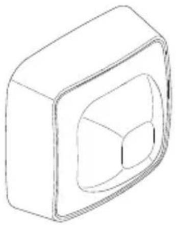
Package contents (Fig. 3.1, Fig. 3.4)
Product dimensions (Fig. 3.2, Fig. 3.5)
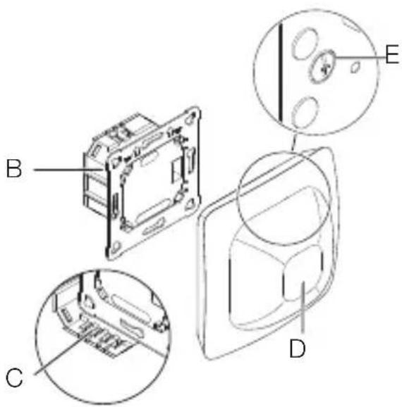
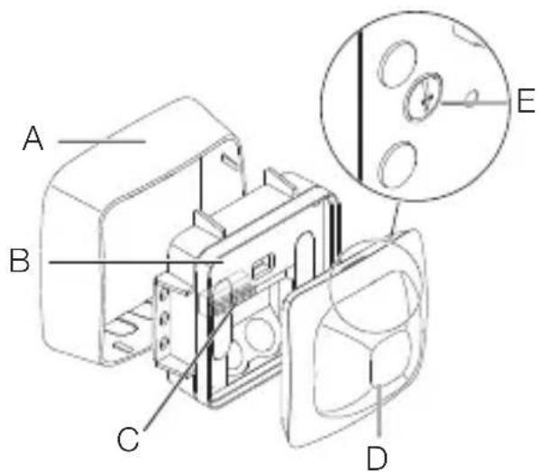
Product components (Fig. 3.3, Fig. 3.6)
A Surface-mounted surround
B Load module
C Connecting terminal
D Sensor module
E Reach adjustment
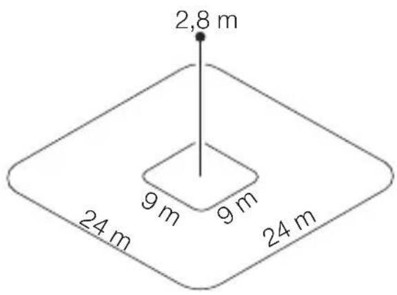
Detection zone (Fig. 3.7)
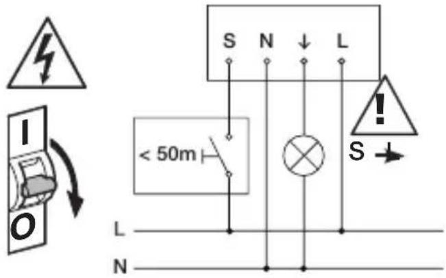
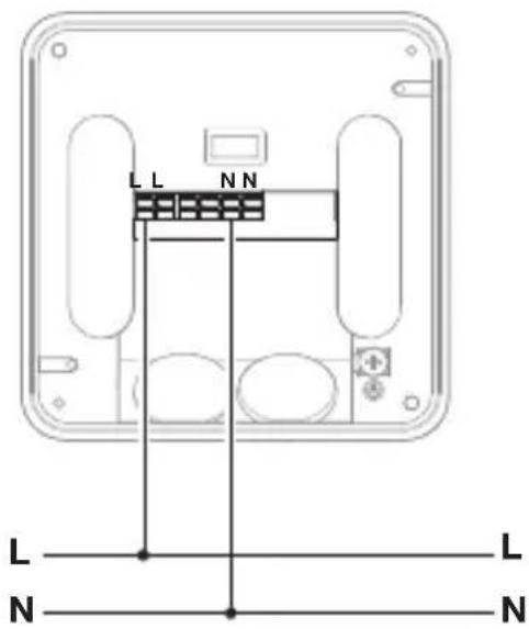
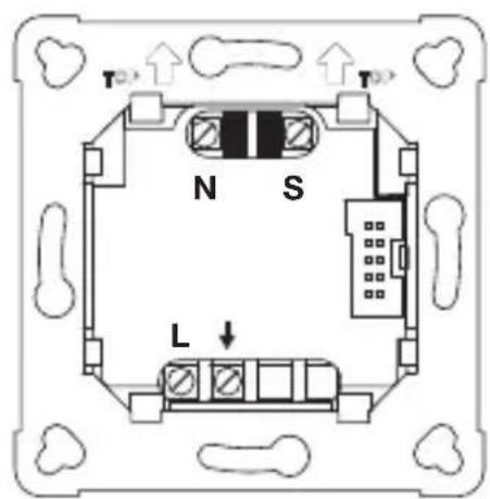
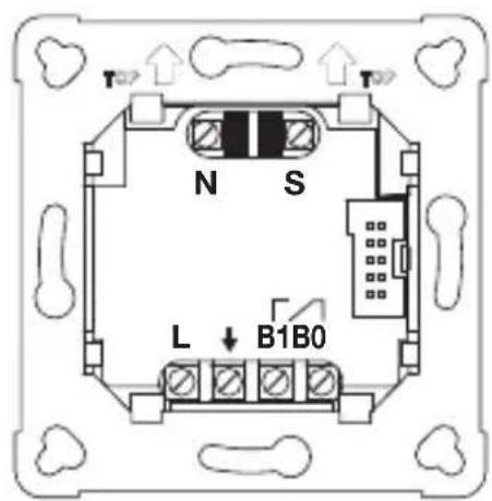
4. Electrical connection
The mains supply lead is a multiple-core cable (max. conductor ∅ 2.5 mm):
L = Phase conductor (usually black or brown)
N = Neutral conductor (usually blue)
PE=Protective-earthconductor (usually green/yellow)
↓ = Switched phase conductor (usually black, brown or grey)
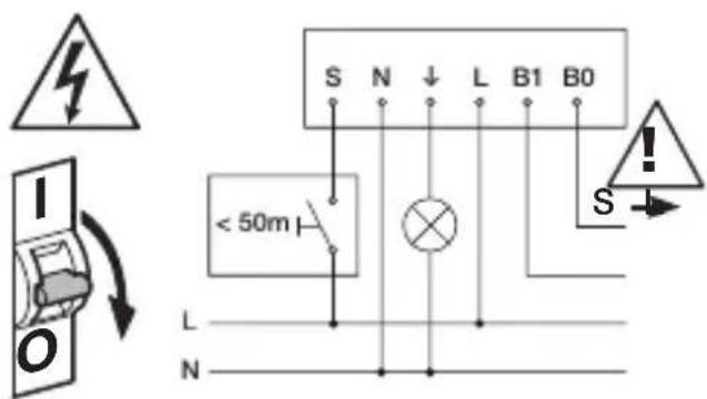
S = Switch
B0/B1 = Floating relay for controlling HVAC
Cable length between sensor and button < 50 m.
Important: Incorrectly wired connections will produce a short circuit later on in the product or fuse box. In this case, you must identify the individual cables and re-connect them.
Connect the mains power supply lead COM1 (Fig. 4.1/4.4/4.7)
Connect the mains power supply lead COM2 (Fig. 4.2/4.5/4.8)
Connect the mains power supply lead BT IPD (Fig. 4.3/4.6/4.9)
5. Installation
- Check all components for damage.
- Do not use the product if it is damaged.
- Select an appropriate mounting location, taking the reach and presence detection into consideration (Fig. 3.7)
Mounting procedure
- Switch off power supply. (Fig. 4.1/4.2/4.3)
Concealed mounting
- Connect to mains power supply. (Fig. 5.1)
- Fit load module and screw into place. (Fig. 5.2)
• Fit magnetic sensor module. (Fig. 5.3) - Switch ON power supply. (Fig. 5.3)
Surface mounting
• Mark drill holes and drill. (Fig. 5.4)
- Screw load module into place. (Fig. 5.5)
- Connect to mains power supply. (Fig. 5.6)
• Fit surface-mounted surround. (Fig. 5.7)
• Fit magnetic sensor module. (Fig. 5.8)
- Switch ON power supply. (Fig. 5.8)
- Make settings.
(→ „6. Function and settings“)
6. Function and settings
Factory settings
The factory settings are activated when the presence detector is put into operation for the first time as well as after resetting by the app.
The following factory settings are provided:
Sensitivity: Sensitivity A: 100%
Sensitivity B: 100%
Sensitivity C: 100%
Sensitivity D: 100%
COM1/COM2 only:
Twilight level: 500 lux
Time setting for COM1: 5 min
Time setting for HVAC: 15 min
Fully/semi-automatic mode:
fully automatic
Switch-ON delays for HVAC: OFF
Setting detection
The detection zone can be also set via the potentiometer (E) on the back of the sensor module in accordance with the table. (Fig. 3.7/6.1)
The sensitivity of the four pyros (A to D) can be set via the app.
Bluetooth grouping
The sensors can be operated as individual sensors or as a group. The group is interconnected via wireless communication.
The COM1 and COM2 versions additionally provide the following functions:
Twilight setting
The chosen response threshold can be set from approx. 2 to 2,000 lux.
Daytime operation
When movement is detected, the sensor switches the load ON irrespective of ambient brightness.
Teach-IN
The Teach-IN function is to be selected at the level of light at which you want the sensor to respond to movement from now on. The level of ambient brightness measured in this way will be saved after 10 seconds. The load is deactivated during this period.
Time setting
The chosen stay-ON time can be set from a minimum of 5 seconds to a maximum of 60 minutes. If no movement is detected, the sensor switches OFF after the stay-ON time expires.
Neighbouring-light function
The neighbouring-light function can be activated and deactivated via the Steinel Connect app. This function assigns the neighbouring groups to the active sensor group. The group responds to activation signals from the neighbouring group assigned to it and switches the light ON as defined in the settings.
Operating mode
Semi-automatic mode
The light now only switches OFF automatically. Light is switched ON manually. Light must be requested using the button and stays ON for the time set.
Fully automatic mode
The light automatically switches ON and OFF in relation to light level when someone is present. Light can be switched ON and OFF manually at any time.
This temporarily interrupts the automatic switching function.
Presentation mode
If light is switched OFF via a push-button, the sensor activates the presentation mode. The load remains switched OFF as long as movement is being detected. As soon as movement is no longer being detected and the stay-ON time has elapsed, the sensor returns to normal sensor mode.
Button input
Push-buttons can be integrated and configured via the STEINEL Connect app. In addition to input S, further push-buttons can be assigned to the sensor from the BT Mesh network. A function can also be assigned to each of these buttons. A pushbutton with the "ON / OFF" function provides the option of switching lighting ON and OFF by hand. However, the "ON" function cannot be used for switching light OFF again. In this case, the stay-ON time is re-started each time the button is pressed. The "OFF" function can only be used to switch lighting OFF manually. "ON x min" and "OFF x min" functions are also available that can be used for switching lighting ON or OFF for a defined period of time. A pushbutton is required for operating the sensor in semi-automatic mode.
Pulse mode
The pulse function activates the output for 2 seconds (E.g. for an automatic stair-case lighting time switch). The sensor will then be in a dead time for 8 seconds.
Steinel Connect App
To read off the sensor via smartphone or tablet, you must download the Steinel Connect app from your app store. You will need a Bluetooth-capable smart-phone or tablet.
Android

text_image
QR code image containing encoded data, no visible human-readable textiOS

text_image
QR code image containing encoded data, no visible human-readable textBluetooth interconnection (Bluetooth Mesh)
The sensor switch complies with the Bluetooth Mesh standard. It can be interconnected with all products complying with the Bluetooth Mesh standard. The sensor switch is configured via the Steinel Connect app. Appropriate network keys are saved on a smartphone or tablet the first time a connection is made between the sensor switch and Steinel Connect app. The key rules out any unauthorised access to the sensor.
The network key must be shared for access via another smartphone or tablet.
LED function
Starting up: The LED flashes white slowly for 10 seconds
Initialisation: The LED lights up blue permanently
Normal mode: LED OFF
Identification: The LED flashes blue slowly
Error: The LED flashes red rapidly
Teach-IN successfully completed:
The LED lights up green for one second
No application available: The lights up in cyan permanently
Movement test mode:
The LED flashes green rapidly
Firmware update: The LED flashes cyan rapidly
7. Maintenance and care
The tool requires no maintenance. Hazard from electrical power.
Contact between water and live parts can result in electric shock, burns or death.
- Only clean tool in a dry state.
Risk of damage to property!
Using the wrong cleaning product can damage the light.
- Clean tool with a moist cloth without detergent.
8. Disposal
Electrical and electronic equipment, accessories and packaging must be recycled in an environmentally compatible manner.

Do not dispose of electrical and electronic equipment as domestic waste.
EU countries only
Under the current European Directive on Waste Electrical and Electronic Equipment and its implementation in national law, electrical and electronic equipment no longer suitable for use must be collected separately and recycled in an environmentally compatible manner.
9. Conformity
STEINEL Vertrieb GmbH hereby declares that the IR Quattro HD-2 COM1/COM2/BT IPD radio equipment type conforms to Directive 2014/53/EU. The full wording of the EU Declaration of Conformity is available for downloading from the following Internet address: www.steinel.de
10. Manufacturer's Warranty
As purchaser, you are entitled to your statutory rights against the vendor. If these rights exist in your country, they are neither curtailed nor restricted by our Warranty Declaration. We guarantee that your STEINEL Professional sensor product will remain in perfect condition and proper working order for a period of 5 years. We guarantee that this product is free from material-, manufacturing- and design flaws. In addition, we guarantee that all electronic components and cables function in the proper manner and that all materials used and their surfaces are without defects.
Making Claims
If you wish to make a claim, please send your product complete and carriage paid with the original receipt of purchase, which must show the date of purchase and product designation, either to your retailer or contact us at STEINEL(UK) Limited, 25 Manasty Road, Axis Park, Orton Southgate, Peterborough, PE2 6UP, for a returns number. For this reason, we recommend that you keep your receipt of purchase in a safe place until the warranty period expires. STEINEL shall assume no liability for the costs or risks involved in returning a product.
For information on making claims under the terms of the warranty, please go to www.steinel-professional.de/garantie
If you have a warranty claim or would like to ask any question regarding your product, you are welcome to call us at any time on our Service Hotline 01733 366700.

- Technische Daten
| Dimensions(L × D × H in mm) | IR-Quattro HD UP: 103 × 103 × 69IR-Quattro HD AP: 123 × 123 × 64 |
| Input voltage 220-240 V, 50/60 Hz | |
| Power consumption• Stand-by < 0,5 W | |
| Capacity, switchingoutput 1: (COM 1/COM 2) | Incandescent/halogen lamp load 2,000 WFluorescent lamps, electronic ballast 1,500 WFluorescent lamps, uncorrected 1,000 VAFluorescent lamps, series-corrected 400 VAFluorescent lamps, parallel-corrected 1,000 VALow-voltage halogen lamps 2,000 VALED < 2 W 100 W2 W < LED < 8 W 300 WLED > 8 W 600 WCapacitive load 176 μF |
| Capacity, switchingoutput 2: (COM 2 only) | AC: max. 1 A @ 230 V AC / 240 W (cos phi = 1)min 0.08 mA @ 230 V ACDC: max 2 A @ 24 Vmin 10 mA @ 5 V, 50 mW |
| Time setting | 10 s to 60 min, |
| Twilight setting | 2-2,000 lux |
| Reach | Presence 9 × 9 mMax. 24 × 24 m |
| Angle of coverage | 360° |
| Mounting height | 2,5-10 m |
| IP rating | IP54 (surface-mounted version only) |
| Temperature range | -20°C to +50°C |
| Bluetooth frequency | 2,4-2,48 GHz |
| Bluetooth transmitter power | 5 dBm/3 mW |
12. Troubleshooting
Malfunction Cause Remedy
| Light does not switch ON ■ | No supply voltage■ Lux setting too low■ No movement detection | ■ Check supply voltage■ Slowly increase lux setting until light switches ON■ Ensure unobstructed sensor vision■ Check detection zone |
| Light does not switch OFF ■ | Lux setting too high■ Stay-ON time running out■ Interfering heat sources: e.g. fan heater, open doors and windows, pets, light bulb/halogen floodlight, moving objects | ■ Reduce lux setting■ Wait until stay-ON time elapses; reduce stay-ON time if necessary■ Check detection zone |
| Sensor switches OFF despite persons being present | ■ Stay-ON time too short■ Light-level threshold too low | ■ Increase stay-ON time■ Change twilight setting |
| Sensor does not switch OFF quickly enough | ■ Stay-ON time too long | ■ Reduce stay-ON time |
| Sensor does not switch ON quickly enough when approached from the front | ■ Reach is reduced when approached from the front | ■ Install additional sensors■ Reduce distance between two sensors |
| Sensor does not switch ON when persons are present despite it being dark | ■ Lux setting too low■ Semi-automatic mode activated■ 4 hours OFF activated | ■ Increase light-level threshold■ Activate fully automatic mode or switch light ON at button■ Deactivate 4 hours OFF |
| Sensor not connecting with the app | ■ App or smartphone system crash | ■ Restart mobile end device |
natural_image
World map silhouette in grayscale, showing continents and oceans without any text or labelsContact
www.steinel.de/contact