
E3S-67 - Capteur de proximité OMRON - Notice d'utilisation et mode d'emploi gratuit
Retrouvez gratuitement la notice de l'appareil E3S-67 OMRON au format PDF.


| Type de produit | Capteur de proximité photoelectrique rétroréfléchissant |
| Modèle | OMRON E3S-67 |
| Distance de détection | 250 mm (avec réflecteur E39-R6) ou 1 m (avec réflecteur E39-R1, distance minimale 250 mm) |
| Objet de détection standard | Tube en verre de 30 mm de diamètre x 150 mm (épaisseur 1,8 mm) |
| Source lumineuse | LED rouge, longueur d'onde 660 nm |
| Tension d'alimentation | 10 à 30 VCC, ondulation résiduelle ≤ 10 % |
| Consommation électrique | 40 mA max. |
| Sortie de commande | NPN/PNP commutable, collecteur ouvert, charge 100 mA max., tension 30 VCC max. |
| Protection intégrée | Courte-circuit, inversion de polarité, interférences mutuelles |
| Temps de réponse | 1 ms max. (marche ou arrêt) |
| Réglage de sensibilité | Potentiomètre 2 tours avec indicateur (lumière ON/OFF commutable) |
| Température ambiante (utilisation) | -25 °C à +55 °C |
| Température ambiante (stockage) | -40 °C à +70 °C |
| Humidité ambiante (utilisation) | 35 % à 85 % HR (sans condensation) |
| Indice de protection | IP67, NEMA 6P (usage intérieur) |
| Matière du boîtier | Zinc moulé sous pression |
| Matière de la lentille | Acrylique |
| Poids (emballé) | Environ 80 g (type connecteur) |
| Dimensions | Environ 50 x 50 x 20 mm (selon schéma de montage) |
| Accessoires inclus | Support de montage, vis, tournevis de réglage, manuel d'utilisation |
| Pièces détachées disponibles | Réflecteurs E39-R6, E39-R1 ; supports E39-L103, E39-L87 ; connecteurs XS2F |
| Entretien et nettoyage | Nettoyer la lentille avec un chiffon doux et sec ; ne pas utiliser de solvants |
| Sécurité | Respecter les tensions et conditions environnementales ; éviter les chocs mécaniques |
| Réparabilité | Réparation par un professionnel qualifié ; pièces détachées disponibles |
FOIRE AUX QUESTIONS - E3S-67 OMRON
Questions des utilisateurs sur E3S-67 OMRON
0 question sur cet appareil. Repondez a celles que vous connaissez ou posez la votre.
Poser une nouvelle question sur cet appareil
Téléchargez la notice de votre Capteur de proximité au format PDF gratuitement ! Retrouvez votre notice E3S-67 - OMRON et reprennez votre appareil électronique en main. Sur cette page sont publiés tous les documents nécessaires à l'utilisation de votre appareil E3S-67 de la marque OMRON.
MODE D'EMPLOI E3S-67 OMRON
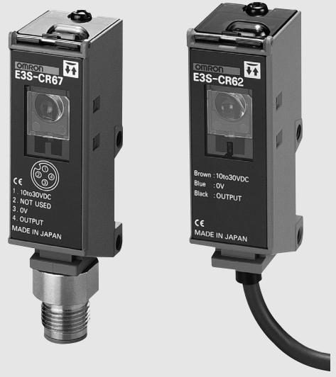
Transparent bottle sensor
E3S-CR62/67
Ideal for detecting transparent glass and plastic containers
C E
Features
Stable operation even if container interval is shortened for higher productivity.
Stable detection of 5mm gaps that previous regression reflection models were unable to detect because of a speed increase for higher productivity.
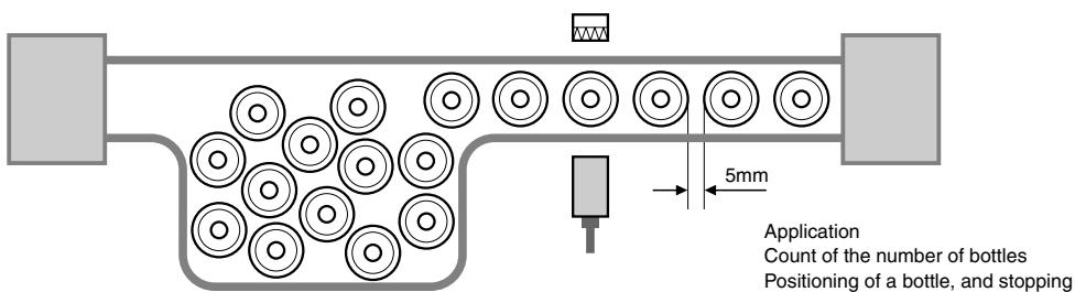
Bottle detection seen from the upper side
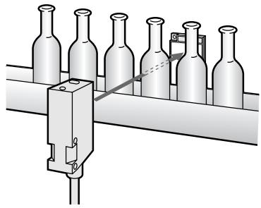
Application
Narrow pin interval detection
Stable detection of 5mm gaps that are not detectable by previous regression reflection models.
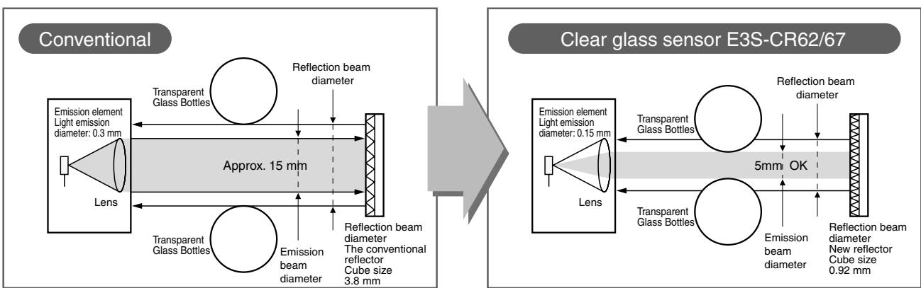
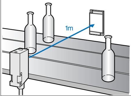
Wide detection range. Stable detection even at long distances.
Use of hyper-point LED as light source (1/2 light emission diameter of previous models) enables stable long-distance detection.
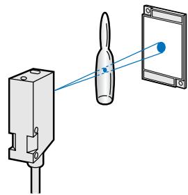
Stable detection of ampules and other small containers.
Visible spotlight for easy adjustment.
Features
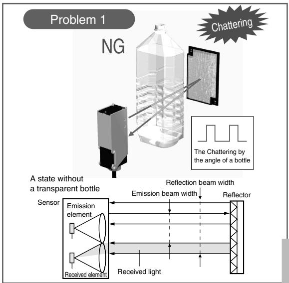
We significantly increased the S/N ratio to enable a stable detection of PET bottles and various other transparent containers
Clear glass sensor E3S-CR62/67
Adoption of the coaxial retroreflective model
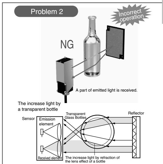
Stable detection can be carried out also to the transparent bottle of various form and surface states.
A state without a transparent bottle
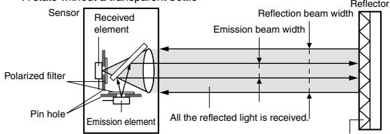
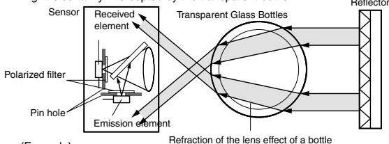
Light is certainly intercepted by the transparent bottle.
(Example)
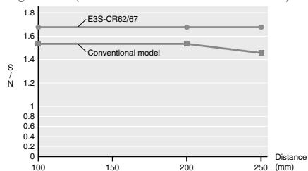
Using E39-R6 (The characteristic in a short distance)
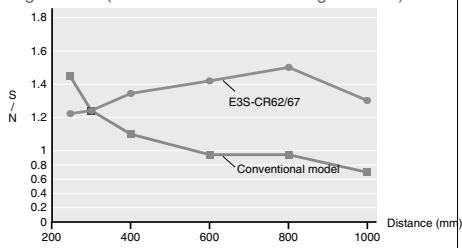
Using E39-R1 (The characteristic in a long distance)
Ordering Information

Sensors
| Sensor type | Shape | Connection method | Sensing distance | Model | |||||||
| Reflector E39-R6 | Reflector E39-R1 | ||||||||||
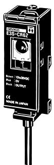
| Retroreflective Models | ← | Pre-wired type | 250mm | 1m | * | E3S-CR62-C | |||||
| Connector type | [250mm] | E3S-CR67-C | |||||||||
- Values in parentheses indicate the minimum required distance between the sensor and reflector.
Accessories (Order Separately)
Reflectors
| Name | Sensing distance | Model | Quantity | Remarks |
| Reflectors | 250 mm | E39-R6 | 1 | --- |
| 1 m (250 mm) * | E39-R1 | 1 |
- Values in parentheses indicate the minimum required distance between the sensor and reflector.
Mounting Brackets
| Shape | Model | Quan-tity | Remarks |
| E39-L103 | 1 | Supplied with the product. | |
| E39-L87 | 1 | --- |
Sensor I/O Connectors
| Cable | Shape | Cable length | Model | |
| Standard cable | Straight | 2 m | 3-wire type | XS2F-D421-DC0-A |
| 5 m | XS2F-D421-GC0-A | |||
| L-shape | 2 m | XS2F-D422-DC0-A | ||
| 5 m | XS2F-D422-GC0-A | |||
Rating/performance
| Sensor type Item | Model | Retroreflective Models (M.S.R. function) | |
| E3S-CR62-C | E3S-CR67-C | ||
| Sensing distance | 250 mm (When using the E39-R6), 1 m (250 mm)*1 (When using the E39-R1) | ||
| Standard sensing object | 30 mm dia. X 150 mm glass tube (thickness: 1.8 mm) | ||
| Directional angle | 2 to 6° | ||
| Light source (wave length) | Red LED (660 nm) | ||
| Power supply voltage | 10 to 30 VDC, ripple (p-p) : 10 % max. | ||
| Current consumption | 40 mA max. | ||
| Control output | Load supply voltage: 30 VDC or less; load current 100 mA or less (residual voltage: NPN output 1.2 V or less, PNP output 2 V or less); open collector model (NPN/PNP output switching) light ON / dark ON switching | ||
| Protective circuits | Load short protection, reverse connection protection, mutual interference protection function | ||
| Response time | Operation or reset: 1 ms max. | ||
| Sensitivity adjustment | 2-turn endless adjuster (with indicator) | ||
| Ambient illuminance | Incandescent lamp: 5,000 lux max. Sunlight 10,000 lux max. | ||
| Ambient temperature | Operating: -25°C to 55°C, Storage: -40°C to 70°C (with no icing or condensation) | ||
| Ambient humidity | Operating: 35% to 85% RH, Storage: 35% to 95% RH (with no icing or condensation) | ||
| Insulation resistance | 20 M min. at 500 VDC | ||
| Dielectric strength | 1,000 VAC at 50/60 Hz for 1 minute | ||
| Vibration resistance | Destruction:10 to 2,000 Hz,1.5 mm double amplitude or 300 m/s² (approx. 30G) for 0.5 hrs each in x, y, and Z directions | ||
| Shock resistance | 1000 m/s² (approx. I00G) 3 times each in X, Y, and Z directions | ||
| Protective structure | IEC Standard IP67 NEMA 6P (restricted to indoor use) *2 | IEC Standard IP67 NEMA 6P (restricted to indoor use) | |
| Connection method | Pre-wired models (standard length: 2 m) | Connector type | |
| Weight (Packed state) | Approx. 115 g | Approx. 80 g | |
| Material | Case | Zinc diecast | |
| Lens | Acrylics | ||
| Display operation panel | Polyethyl sulfon | ||
| Mounting Brackets | Stainless steel (SUS304) | ||
| Accessories | Brackets (with screws), adjustment driver, operation manual | ||
1. Values in parentheses indicate the minimum required distance between the sensor and reflector.
2. NEMA (National Electrical Manufacturers Association) Standard
Output Circuit Diagram
NPN output
| Model | Operating status of output transistor | Timing chart | Mode selection switch | Output circuit |
| E3S-CR62-C | Light ON | Incident Interrupted ON OFF | L ON (LIGHT ON) | Brown 10 to 30 VDC Load Control output Blue 0V |
| E3S-CR67-C | Load (Relay) Operate Reset (Between brown and black) | |||
| Dark ON | Incident Interrupted Light indicator ON OFF | D ON (DARK ON) | * Please make a changeover switch into the NPN side. Connector Pin arrangement Note: Pin 2 is not used. | |
| Load (Relay) Operate Reset (Between brown and black) |
PNP output
| Model | Operating status of output transistor | Timing chart | Mode selection switch | Output circuit |
| E3S-CR62-C | Light ON | Incident Interrupted ON (Red) OFF (Yellow) Load (Relay) Operate (Between blue and black) | L ON (LIGHT ON) | Brown 0 to 30 VDC |
| Main circuit NPN and PNP output selector Black Control output Load current Blue Load current | ||||
| E3S-CR67-C | ||||
| Dark ON | Incident Interrupted Light indicator (red) ON OFF (Yellow) Load (Relay) Operate (Between blue and black) | D ON (DARK ON) | * Please make a changeover switch into the NPN side. Connector Pin arrangement ②④③ Note: Pin 2 is not used. |
Connectors (Sensor I/O connectors)

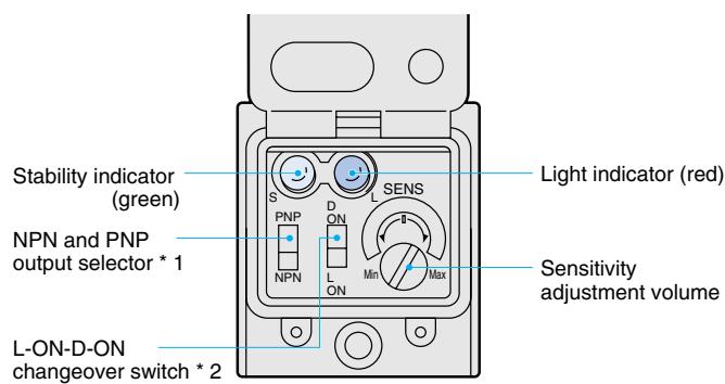
1. Output transistor switching is possible by means of NPN/PNP output switch.
2. Operation mode can be switched using L ON/D ON switch.
Operation
Sensitivity adjustment
The light source switch and reflective plate can be moved horizontally and vertically to set them in the center of the illumination area of the red incident light indicator lamp, allowing the operator to check whether the green stability indicator lamp is illuminated.
| Sensing object | Detection state | Sensitivity adjuster | Indicator state | Adjustment procedure |
| Transparent pin or glass plate | Without sensing object | Min Max | ON Stability indicator (green) Light indicator (red) | Turn sensitivity control from minimum to maximum and set at point where incoming light stabilizes. |
| Opaque object | Object detected, object not detected | Min Max | ON Stability indicator (green) Light indicator (red) | If the object is larger than the lens diameter, set the sensitivity control to the maximum setting. If the object is the same size or smaller, turn the sensitivity control from minimum to maximum and set at point where incoming light stabilizes. |
Correct Use
Design
Fuzzy mutual interference prevention
- If the light source switches for the reflective plates are arranged in a row, light from a neighboring light source switch may be received, causing erroneous light reception signals and errors.
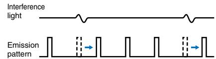
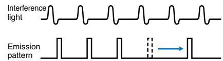
- The fuzzy reciprocal interference prevention function monitors interference light for a certain period of time before illumination, and gathers data on the strength of the interference light and the frequency of incidence. It then determines the risk of error due to these two factors using fuzzy logic and controls the timing of illumination to reduce the risk.
(When risk is low)
- Light is emitted after interfering light is gone.
(In case of high risk)
- Light is emitted after shifting to a gap of interfering light.
Bottles
In some cases, factors such as the shape of a bottle prevent stable detection. Please confirm that a correct detection is performed before use.
Wiring Considerations
Cable
- An oil resistant cable is used to ensure oil resistance. Avoid repeated bending of the cable.
- The bending radius should be 25mm or more.
Avoiding Malfunctions
When using a photoelectric switch with an inverter or sub-motor, be sure to connect FG (frame ground pin) and G (ground pin). If not connected, errors may result.
Installation
Sensor installation
- When installing a photoelectric switch, avoid tapping with a hammer. This may damage the water resistance function.
- Use an M4 screw, tightened to a torque of no more than 1.18 Nm.
(When using the mounting bracket)
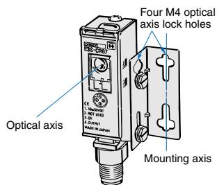
- To set the sensor on the mechanical axis, use the optical axis locking holes.
- When it is not possible to mount on the mechanical shift, move the photoelectric switch vertically or horizontally so that it is located in the center of the area illuminated by the incident light indicator lamp. Verify that the stability indicator lamp is on.
(Direct installation)
Install the photoelectric switch as shown in the following diagram.
Tighten M4 screw
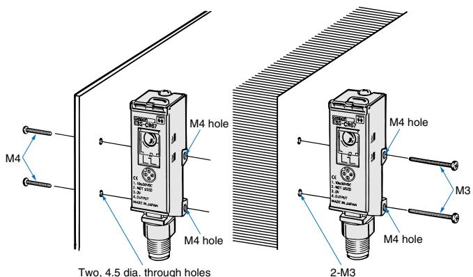
Tighten M3 screw
For adjustment
Light axis adjustment
Adjust the optical axis of the clamp to the direction of detection object approach. The optical axis of the photoelectric switch is the same as the mounting axis of the clamp, enabling easy adjustment.
Optical axis locking hole
By fitting screws into the optical axis locking holes, the mounting bracket is set onto the mounting shaft of the mounting bracket.
Sensors
Retroreflective Models
Pre-wired
E3S-CR62-C
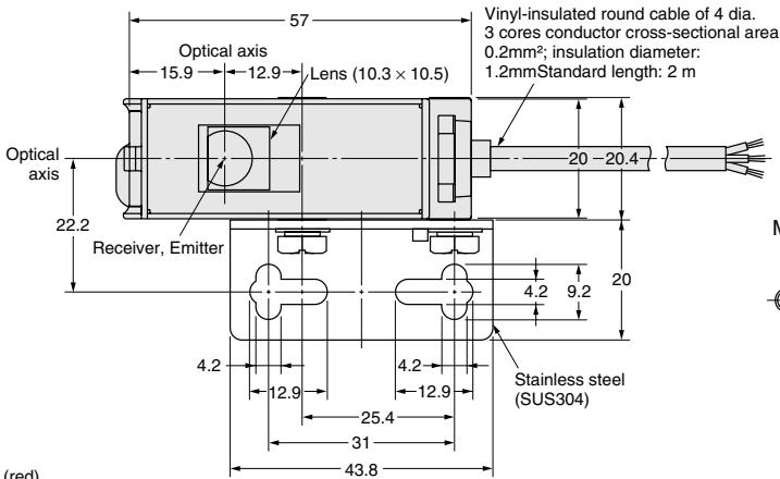
With Mounting Blanket Attached

Mounting Holes
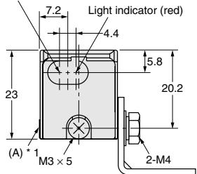
Stability indicator (green)
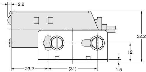
* Mounting Bracket can be attached to side A.
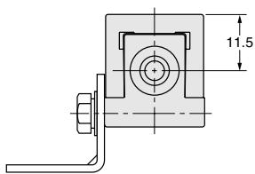
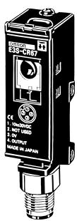
Connector type
E3S-CR67-C
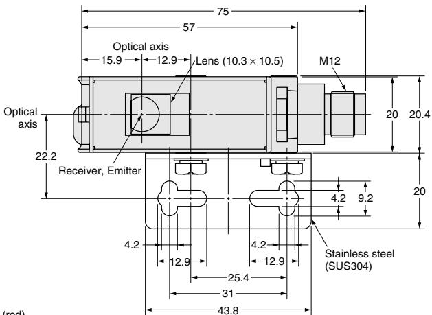
With Mounting Blanket Attached
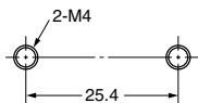
Mounting Holes
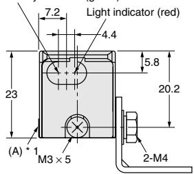
Stability indicator (green)
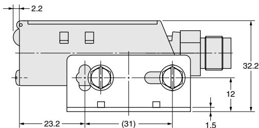
* Mounting Bracket can be attached to side A.
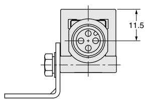
Accessories (Order Separately)
H-3
ALL DIMENSIONS SHOWN ARE IN MILLIMETERS.
To convert millimeters into inches, multiply by 0.03937. To convert grams into ounces, multiply by 0.03527.
- Transparent bottle sensor
- E3S-CR62/67
- Features
- Application
- Ordering Information
- Accessories (Order Separately)
- Output Circuit Diagram
- Connectors (Sensor I/O connectors)
- Operation
- Sensitivity adjustment
- Correct Use
- Design
- Fuzzy mutual interference prevention
- (When risk is low)
- Bottles
- Wiring Considerations
- Cable
- Avoiding Malfunctions
- Installation
- Sensor installation
- (Direct installation)
- Tighten M4 screw
- Light axis adjustment
- Optical axis locking hole
- Sensors
- Retroreflective Models
- H-3
Marque : OMRON
Modèle : E3S-67
Catégorie : Capteur de proximité