
E3NT-R - Capteur de proximité OMRON - Notice d'utilisation et mode d'emploi gratuit
Retrouvez gratuitement la notice de l'appareil E3NT-R OMRON au format PDF.


| Type de produit | Capteur photoélectrique rétro-réfléchissant polarisé |
| Marque | OMRON |
| Modèle | E3NT-R |
| Dimensions (L x l x P) | 85 x 27 x 65 mm |
| Poids | Environ 200 g |
| Alimentation | 24 V DC (plage 10-30 V DC, polarisé) |
| Consommation électrique | < 110 mA (affichage allumé, chauffage vitre éteint) |
| Distance de détection nominale | 16 m avec réflecteur E39-R8 |
| Zone morte | 200 mm minimum entre capteur et réflecteur |
| Type de sortie | Configurable : PNP, NPN, push-pull (complémentaire) |
| Fonctions principales | Détection d'objets, sortie commutation, alarme encrassement, délais, verrouillage clavier, mode ECO |
| Configuration | Par boutons poussoirs sur le capteur ou par PC via interface optique E3NT-AL232 |
| Affichage | Affichage LED 4 chiffres 7 segments + 2 LEDs d'état |
| Indice de protection | IP 67 (EN 60529) |
| Température de fonctionnement | -25°C à +55°C (sans chauffage vitre) / -40°C à +55°C (avec chauffage vitre) |
| Matériau du boîtier | Aluminium poudré (231 GD AlSi12(Cu)) |
| Raccordement | Connecteur M12, 5 pôles |
| Entretien et nettoyage | Nettoyer la vitre optique avec un chiffon doux non abrasif ; pas de maintenance régulière |
| Sécurité | Ne pas utiliser comme composant de sécurité ; installation et maintenance par personnel qualifié |
| Accessoires fournis | Notice abrégée, CD-ROM avec logiciel S3 et manuel |
| Pièces détachées et accessoires | Supports (E39-EL1, E39-EL2, E39-EL4), réflecteurs (E39-R7, E39-R8…), câbles, interface optique, aide laser E3NT-AP1 |
| Réparabilité | Réparation uniquement par le fabricant ; retour au fournisseur |
FOIRE AUX QUESTIONS - E3NT-R OMRON
Questions des utilisateurs sur E3NT-R OMRON
0 question sur cet appareil. Repondez a celles que vous connaissez ou posez la votre.
Poser une nouvelle question sur cet appareil
Téléchargez la notice de votre Capteur de proximité au format PDF gratuitement ! Retrouvez votre notice E3NT-R - OMRON et reprennez votre appareil électronique en main. Sur cette page sont publiés tous les documents nécessaires à l'utilisation de votre appareil E3NT-R de la marque OMRON.
MODE D'EMPLOI E3NT-R OMRON
Retro-Reflective Sensor E3NT-R
Photoelectric Sensor
OPERATION MANUAL
Table of Contents
SECTION 1: Important Precautions. 3
1-1 Using the operating instructions 3
1-2 Use in accordance with the intended purpose 3
1-3 Use that is not in accordance with the intended purpose 3
1-4 Warranty and liability 3
1-5 Key to symbols 3
1-6 Abbreviations 3
SECTION 2: Safety Notes. 5
2-1 Safety notes 5
SECTION 3: Specification. 7
3-1 Specifications of Retro-reflective sensor E3NT-R_7. 7
3-1-1 General data. 7
3-1-2 Optical data 7
3-1-3 Mechanical data 7
3-1-4 Electrical data 8
3-2 Specifications of Optical data link E3NT-AL232 (order separately) 8
3-3 Specifications of Laser alignment aid E3NT-AP1(order separately) 9
3-4 Dimensions. 9
3-4-1 Sensor E3NT-R17 and E3NT-RH17 (with horizontal connector) 9
3-4-2 Sensor E3NT-R37 and E3NT-RH37 (with vertical connector) 10
3-4-3 Universal mounting bracket E39-EL1 (order separately) 10
3-4-4 Adapter bracket E39-EL2 (order separately) 11
3-4-5 Optical data link E3NT-AL232 2m (order separately) 11
3-4-6 Alignment bracket E39-EL4 (order separately). 12
3-4-7 Laser alignment aid E3NT-AP1 (order separately) 12
3-4-8 Retroreflectors (order Separately). 13
SECTION 4: Function 15
4-1 Functions. 15
4-2 Display and operator controls 15
4-2-1 LED display 15
4-2-2 LEDs. 15
4-2-3 Push buttons on the sensor 16
4-2-4 Set-up via a PC. 16
4-3User set parameters 16
4-3-1 Output function 16
4-3-2 Output switching 17
4-3-3 Function of connector pin 2 and 5. 17
4-3-4 Switch-on delay. 17
4-3-5 Switch-off responses. 17
4-3-6 Timing diagrams 18
4-3-7 Keyboard lock 18
4-3-8 ECO energy saving mode. 18
4-3-9 Reset. 18
4-4 Inputs/Outputs. 18
4-4-1 Input: Test input TEST 18
4-4-2 Outputs 19
SECTION 5: Transport 21
5-1 Packaging/Transportation damage 21
5-2 Storage 21
5-3 Scope of delivery 21
SECTION 6: Mechanical installation of the sensor 23
6-1 Safety notes 23
6-2 Sensor assembly. 23
6-2-1 Sensor's assembly direction 23
6-2-2 Assembly via assembly holes 24
6-2-3 Assembly by universal mounting bracket E39-EL1 24
6-2-4Assembly with adapter bracket E39-EL2 and bracket E39-EL1 24
SECTION 7: Electrical Connection 25
7-1 Safety notes 25
7-2 Establishing electrical connection 25
7-3 Connection diagrams 26
7-3-1 Output circuits 26
7-3-2 Input circuits 26
7-3-3 Connector pin assignments 27
7-4 Connection in line with EMC requirements. 27
SECTION 8: Setting into Operation 29
8-1 Safety notes 29
8-2 Switching on the operating voltage. 29
8-3 Aligning the sensor 29
SECTION 9: Configuration 31
9-1 Setting the sensor using the push buttons 31
9-1-1 Display in the normal mode 31
9-1-2 Main menu structure 31
9-1-3 SET menu path. 32
9-1-4 OPTIONS menu path 33
9-2 Setting the sensor with a PC 34
SECTION 10: Maintenance and Repair 35
10-1 Maintenance 35
10-2 Repair 35
SECTION 11: Accessories and Parts 37
SECTION 1: Important Precautions
1-1 Using the operating instructions
These operating instructions refer exclusively to retro - reflective sensors in the E3NT type series. They contain the most important notes for operating the sensor in line with safety requirements.
The operating instructions must always be close at hand and accessible at all times, and must be kept together with the higher-level machine installation. The contents of these operating instructions must be read and understood, and all its points must be followed by everyone who is responsible for machine planning, assembly and operation. This particularly applies to the safety notes.
Observance of the safety notes will help to avoid accidents, malfunctions and faults.
1-2 Use in accordance with the intended purpose
Retro - reflective sensors in the E3NT type series are always operated as part of a higher-level overall system, e.g. a machine installation. They may only be used as optical sensors to check the presence of objects within a machine installation with a higher-level control system.
Any other use, or any use exceeding this scope, is not permitted. Use in accordance with the intended purpose also includes observance of the operating instructions and keeping to the inspection and maintenance specifications in accordance with the system documentation.
1-3 Use that is not in accordance with the intended purpose
Retro - reflective sensors in the E3NT type series must not be used as safety components within the scope of the EU machine guideline. Its use in applications in which the safety of persons depends on functioning of the sensor is not permissible!
1-4 Warranty and liability
Our Terms and Conditions of Delivery and Payment fundamentally apply. These are available to the owner at the latest as from conclusion of a contract. Warranty and liability claims for personal injury and property damage are ruled out if they are attributable to one or several of the following causes:
- Use of the sensor that is not in accordance with its intended purpose
- Improper assembly, commissioning and maintenance of the sensor
- Failure to observe the notes in the operating instructions in relation to transport, storage, assembly, commissioning and maintenance of the sensor
- Unauthorized structural changes to the sensor
- Repairs carried out improperly
- Disasters resulting from the influence of foreign bodies and acts of God.
1-5 Key to symbols
The following symbols are used in these operating instructions:

Important information

Risk of damage to the machine or material

Risk of injury to life and limb in general
1-6 Abbreviations
The following abbreviations are used in these operating instructions:
- IR: InfraRed
PC: Personal Computer
SECTION 2: Safety Notes
2-1 Safety notes

The retro-reflective sensors belonging to the E3NT type series may only be used as described in these operating instructions. They may only be operated as part of a higher-level overall system, e.g. a machine installation.

During machine planning and the use of retro-reflective sensors belonging to the E3NT type series, the safety and accident prevention regulations that are specific to use must be observed, e.g.:
EN 292, Safety of machines, general design principles
EN 60204, Electrical equipment of machines

Retro-reflective sensors belonging to the E3NT type series must not be used as safety components within the scope of the EU Machine guidelines.
Their use in applications in which the safety of persons depends on functioning of the sensor is not permissible!

The manufacturer and owner of the higher-level overall system, e.g. of a machine installation, is responsible for conformity with the national and international safety and accident prevention regulations that apply to the special application.

Assembly, electrical connection and maintenance may only be carried out by instructed, trained and authorized specialist personnel in accordance with applicable regulations after de-energizing the power supply and switching off the machine.
The machine must be safeguarded against reactivation.

Conversions and changes as well as tampering with the interior of the sensor, the data link and the alignment tool are forbidden. The notes contained in these operating instructions, in particular the chapters entitled Safety notes and Maintenance and repair, must be integrated into the operating instructions of the higher-level overall system.
SECTION 3: Specification
3-1 Specifications of Retro-reflective sensor E3NT-R_7
3-1-1 General data
| Sensor type E3NT-R_7 | • Polarized Retro-reflective sensor |
| Options | • Window heating |
| User settings / configuration | • By push button on the sensor or • with a PC connected via the optical data link |
| Optical data link (order separately) | • Set-up configuration via a PC / Laptop, • real-time visualization of sensor data • value output and logging, • firmware update |
3-1-2 Optical data
| Emitted light | • red LED (660 nm) (polarized light) |
| Rated sensing distance | • 16 m (when using E39-R8) |
| minimum required distance between sensor and reflector (dead zone) | • 200 mm |
| standard sensing object | • opaque with a diameter of about 100mm |
| ambient light immunity: Halogen source and sunlight Fluorescent lamps Energy saving lamps spot diameter | • 10,000 lux max. • 5,000 lux max. • 2,000 lux max. • about 100mm at 10m distance |
3-1-3 Mechanical data
| dimensions (length x width x depth) | 85 x 27 x 65 mm |
| materials | |
| Housing | Powder-coated aluminum (231 GD AISil2 (Cu)) |
| Front and top panel | Glass |
| Keyboard | HTV silicone |
| Seals | RTV silicone |
| housing color | Grey (RAL 7030) |
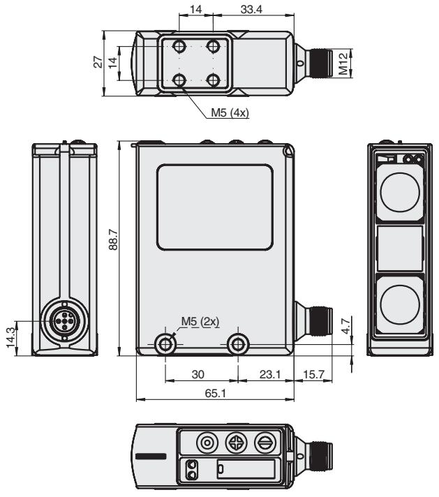
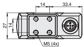
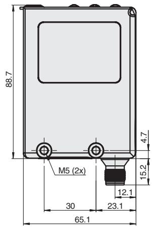
| assembly possibilities | Screw fastening by way of four M5 threads and two M5 through holes or with universal mounting bracket (order separately) |
| connection method | M12, 5-pole connector |
| operation ambient temperature | - 25°C to + 55°C (without pane heating) - 40°C to + 55°C (with pane heating) |
| storage ambient temperature | - 40°C to + 70°C |
| ambient relative humidity | 35 % to 95 %, no condensation |
| enclosure rating (EN 60529) | IP 67 |
| protection class | II (50 V DC) |
| shock resistance (EN 68000-2-27) | 300 m/s², 3 times each axis X, Y, Z |
| vibration resistance (EN 68000-2-6) | ± 1.5 mm double amplitude for 1h, 10-70 Hz, each axis X, Y, Z |
| weight | approx. 200g |
3-1-4 Electrical data
| Rated operating voltage | + 24 V DC, polarized (for Firmware update U>16V DC nees-sary) |
| Operating voltage range | + 10 V DC to + 30 V DC (incl. 10% ripple (p-p)) |
| Current consumption | < 110 mA (for the display on; pane heating off< 90 mA (for the display off; pane heating off)< 200 mA (for the display on; pane heating on)< 180 mA (for the display off; pane heating on) |
| Power-on delay | < 300 ms |
| Inputs - / Output - pins | Pin 2 = input (In 2) or output (Out 2) depending on configurationPin 4 = output (Out 1)Pin 5 = Input (In 1) |
| outputs | selectable:switching outputalarm output (dirt detection) |
| output circuit | selectable:PNP (open collector) (default setting)NPN (open collector)complementary (push-pull) |
| output power voltage | 30 V DC max. |
| output current | 100 mA max. |
| residual voltage | < 2,0 V max. |
| residual current | < 100 μA |
| circuit protection | • Reversed power supply connection• overload (load short circuit)• short-circuit (pulsed) |
| Inputs | • test input |
| Input circuit | Voltage input +10 V ... U Supply |
| Input pulse duration | 1 ms min. |
| Switch-on / -off time (T ON / T OFF) | ≤ 2.5 ms |
| Insulation resistance | 20 MΩ at 500 V DC |
| Insulation dielectric strength | 1 kV AC, 50/60 Hz for 1 min |
3-2 Specifications of Optical data link E3NT-AL232 (order separately)
| Dimensions (length x width x depth) | 29.5 x 72.9 x 26.4 mm |
| Housing material | ABS and PMMA (IR transparent) |
| Housing color | Black, RAL 9005 |
| Assembly | Snap mounting on sensor |
| Connection | 2 m connecting cable with 9-pole sub-D connector |
| Ambient temperature range | - 10 °C ... + 50 °C |
| Storage temperature range | - 40 °C ... + 60 °C |
| Permissible relative humidity | 35 % ... 85 %, no condensation |
| Degree of protection to EN 60529 / IEC 529 | IP 54 |
| Emitted light | IR communication element 880 nm |
| Rated operating voltage | Via RS232 interface from PC |
| Current consumption | 6 mA |
3-3 Specifications of Laser alignment aid E3NT-AP1(order separately)
| Supply voltage | 3V DC |
| battery type | button battery ∅ 11,6mm, thickness: 5,4mm, 3V type: CR1/3N |
| Ambient temperature | operation: 10 to 40°C storage: -10 to +60°C (with no icing or condensation) |
| Ambient humidity | Operation & storage : 35% to 85% (with no icing or condensation) |
| Ambient environment | No corrosive gases |
| Operation time period | min. 5 hours operation with 1 new battery |
| Degree of protection | IP20 (IEC60529) |
| Case material | case: ABS/PC base plate: Aluminum |
| Weight | Approx. 42g |
| Accessories | • 1 Instruction sheet • 1 battery type CR1/3N |
| max. distance for a visible beam spot | about 50m (depending on the ambient light and surface conditions) |
| laser beam power | < 1mW |
| laser class | Laser Class II |
3-4 Dimensions
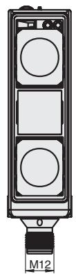
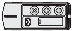
3-4-1 Sensor E3NT-R17 and E3NT-RH17 (with horizontal connector)
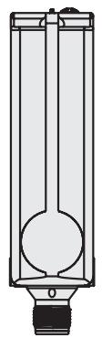
3-4-2 Sensor E3NT-R37 and E3NT-RH37 (with vertical connector)
3-4-3 Universal mounting bracket E39-EL1 (order separately)
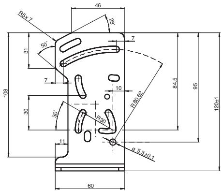
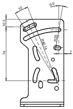

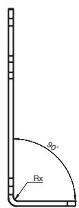
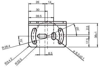
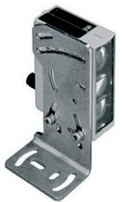
material: stainless steel 1.4305
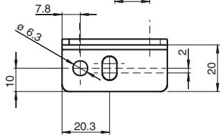
3-4-4 Adapter bracket E39-EL2 (order separately)
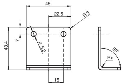
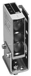
material: stainless steel 1.4305
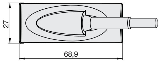
3-4-5 Optical data link E3NT-AL232 2m (order separately)
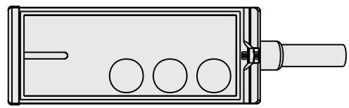
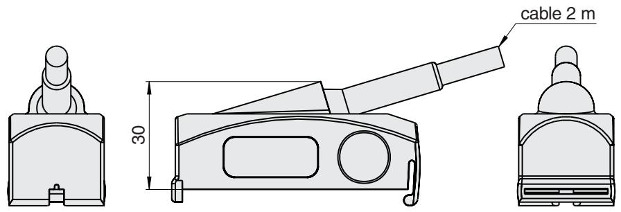
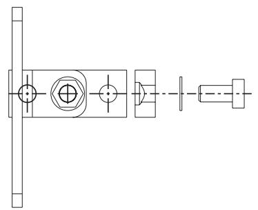
3-4-6 Alignment bracket E39-EL4 (order separately)
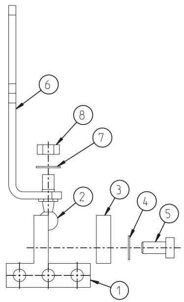
| Part | Quantity | Description |
| 1 | 1 | base part |
| 2 | 1 | ball - and socket joint |
| 3 | 1 | counter pressure part |
| 4 & 7 | 2 | washer |
| 5 | 1 | screw M5 |
| 6 | 1 | bracket |
| 8 | 1 nut | |
| material zinc - coated steel | ||
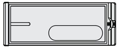
3-4-7 Laser alignment aid E3NT-AP1 (order separately)

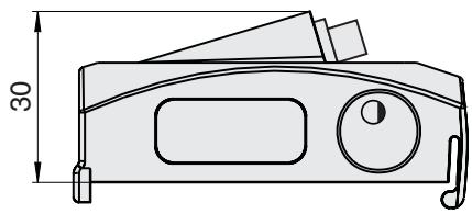
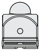
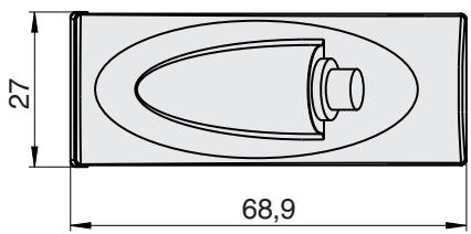
3-4-8 Retroreflectors (order Separately)
3-4-8-1 E39-R7 (0 84 mm)

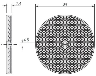
3-4-8-2 E39-R8 (100 mm x 100 mm)
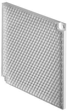
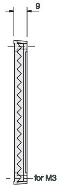
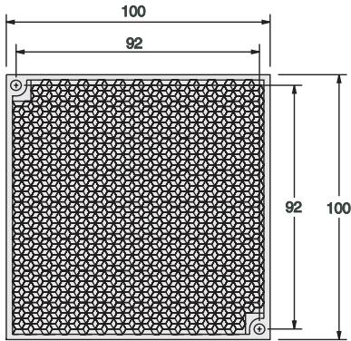
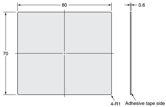
3-4-8-3 E39-R40 (80 mm x 80 mm)
3-4-8-4 Adhesive tape E39-RS1
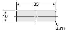
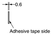
3-4-8-5 Adhesive tape E39-RS2

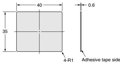
3-4-8-6 Adhesive tape E39-RS3
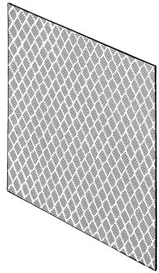
SECTION 4: Function
4-1 Functions
Retro-reflective sensors in the E3NT type series are operated with retro-reflectors. The emitted light is polarized. The light is reflected by the retro-reflector and the polarization of the light is changed. The reflected light is detected by the receiver element, which is integrated in the sensor.
If the light spot is not completely interrupted by the object, the object may not be detected correctly.
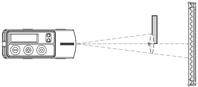
The sensor can be user set by push button on the unit or with a PC and the SensorSupportSoftware S3 via an optical data interface E3NT-AL232 (order separately). The optical data interface operates with an IR communication element. Through the optical data interface, the receiver light intensity data can also be transferred continuously to a PC/ laptop and stored there (data logging).
4-2 Display and operator controls
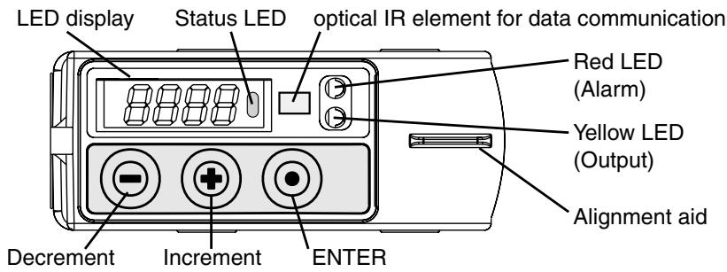
Operating states are displayed by a 4-digit 7-segment LED display and two LEDs. The sensor can be operated/set either by push buttons on the sensor or with a PC and setting software (order separately) via an optical data interface (order separately).
4-2-1 LED display
The light intensity of the received light and the names of the menu levels during set-up of the sensor are displayed by the 4-digit 7-segment LED display. The display appears as red digits or letters or green LED bar chart.
4-2-2 LEDs
The switching status and the stability of the output are signaled by three LEDs. Two of them are visible from the top and the front of the sensor:
- Yellow LED:
ON:
Object stably detected
OFF:
No object within range
Red LED:
ON:
Alarm output on
OFF:
normal function
- Status LED - The status LED is only visible from the top of the sensor:
ON: Set-up menu selected
Blinking: Menu level with change
OFF: RUN (normal) mode
4-2-3 Push buttons on the sensor
On the sensor, there are three push buttons for the setting of the sensor:
- Minus key

- Plus key

Enter key

With these three push buttons, the operator moves through the sensor's menu and sets the parameters in accordance with the application. Therefore, all parameters can be set directly on the sensor.
4-2-4 Set-up via a PC
All parameters of the sensor can be set also with a PC (or Laptop) and the OMRON SensorSupportSoftware S3. The connection between the sensor and the PC is established via an optical data interface (E3NT-AL232 2m). The data interface is connected to a free COM port of a PC/laptop. Also the USB - RS232 Converter of OMRON can be used to realize the connection. Refer to the separate operating instructions ABBO0018 for further information on setting with a PC and the SensorSupportSoftware S3.
4-3 User set parameters
The following parameters can be user set either by push buttons on the sensor or with a PC and the set-up software S3 via the optical data interface (order separately):
Output function
Output switching
- Function on connector pins 2 and 5
- Switch-on and off delay
Type of time delay function
Keyboard lock
Energy saving mode
Display direction
- Reset to factory defaults
The following functions can only be set with a PC and the set-up software S3 via the optical data interface (order separately):
- Complete sensor locking
4-3-1 Output function
The output function can be set for the output:
Light on (factory default):
The output is active when the reflected light is detected at the receiver.
Dark on:
The output is active when no reflected light is detected at the receiver.
4-3-2 Output switching
Output switching can be user set jointly for both outputs:
PNP:
The output is set to plus-switching with open collector.
NPN:
The output is set to minus-switching with open collector.
- Push-pull:
The output is set to complementary (plus/minus-switching) (factory default).
Refer to 7-3 Connection diagrams.
4-3-3 Function of connector pin 2 and 5
Pin 2 of the connector can be user set as an alarm output or as a test input.
Pin 5 of the connector can be user set as a test input or switched off (factory default).
4-3-4 Switch-on delay
This defines the switch-on response. The time is adjustable between 0 ms and 9999 ms.
- Switch-on delay:
The switch-on delay starts as from the time when the measured object enters the sensing zone. The output does not become active until the switch-on delay has elapsed.
4-3-5 Switch-off responses
This defines the switch-off response. The time is adjustable between 0 ms and 9999 ms. There are 3 different kind of responses possible:
- Switch-off delay:
The switch-off delay starts as from the time when the measured object leaves the sensing zone. The output does not become inactive until the switch-off delay has elapsed.
- Minimum pulse width:
After detection of a measured object, the output remains active for at least the user set switch-off delay. If the measured object dwells in the sensing zone for longer than the set minimum pulse width, then the output becomes inactive immediately after the object leaves the sensing zone.
- Constant pulse width:
After detection of a measured object, the output only remains active during the user set constant pulse width and becomes inactive after this time has elapsed, regardless of the measured object's dwell time, even if the measured object stays in the sensing zone for longer than the user set switch-off delay.
4-3-6 Timing diagrams
Timer functions off
| object | detected |
| not detected | |
| ON | |
| OFF |
Mode on-1 (on/off-1-delay)
| object | detected |
| not detected |
| only on-delay | ON |
| OFF |
| only off-delay | ON |
| OFF |
on - and off-delay
Mode on-2 (minimum pulse width)
| object | detected |
| not detected |
ON OFF
Mode on-3 (constant pulse width)
ON OFF

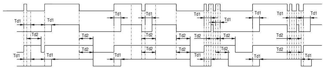

+on-delay:Td1
+off-delay:Td2
+min/+genau:Td3
4-3-7 Keyboard lock
With the keyboard lock function, the push buttons on the sensor can be locked to prevent inadvertent modification of the settings.
The lock can be activated and deactivated on the sensor. When the keyboard lock is active, changes can only be made after the Minus and Plus keys have been pressed simultaneously for 4 seconds. This temporarily suppresses the keyboard locking. If no key is pressed for about 150 seconds, the keyboard lock is automatically activated again.
4-3-8 ECO energy saving mode
In the ECO mode, the display switches off automatically approximately 3 minutes after the push buttons have been pressed for the last time.
The display is activated again the next time the push buttons are pressed. Deactivation of the sensor display reduces the sensor's current consumption by approximately 20mA .
4-3-9 Reset
Reset returns the sensor to the factory default settings.
4-4 Inputs/Outputs
In total, the sensor can be operated with a maximum of three inputs/outputs. The functions of the inputs/outputs are user determined.
Connector pin 4 is always defined as output (OUT).
Connector pin 2 can be set as alarm output (ALARM), as test input (TEST).
Connector pin 5 can be set as test input (TEST) or OFF.
4-4-1 Input: Test input TEST
Connector pins 2 or 5 can be set as test input.
The emitter is deactivated if a signal in the operating voltage range is applied to this input. Depending on the absence of a detection object the sensor alters it's output, because no light is emitted.
4-4-2 Outputs
4-4-2-1 Switching output OUT
When a measured object is detected, the switching output OUT (Connector pin 4, fixed) switch in accordance with the sensor's output function settings.
4-4-2-2 Alarm output ALARM
Connector pin 2 can be set as the alarm output. The alarm output is switched on if the intensity of reflected light from the reflector is too low. In this case, the sensor may be covered with dust. Please clean the sensor and check the alarm output again. This condition is indicated by the red LED too.
SECTION 5: Transport
5-1 Packaging / Transportation damage
- During transportation, please ensure that the sensor is not damaged by other objects.
- For transportation, only ever use the sensor's original packaging sealed properly.
- Keep the sensor's original packaging for later use.
Report transportation damage immediately in writing to the haulage contractor and OMRON.
5-2 Storage
- For storage keep the sensor in original packaging that has been sealed properly.
- Protect the sensor against dust and moisture.
5-3 Scope of delivery
The sensor's scope of delivery consists of:
- Retro-reflective Sensor E3NT-R
Short-form instruction sheet - CD-ROM containing the S3 software, this operation manual, the S3 software manual and the Acrobat Reader software.
SECTION 6: Mechanical installation of the sensor
6-1 Safety notes

Assembly, electrical connection and maintenance must only be carried out by instructed, trained and authorized specialist personnel in accordance with applicable regulations, after de-energizing the power supply and with the machine switched off.
The machine must be safeguarded against reactivation.

Conversions and changes and tampering in the interior of the sensor, the data interface and the alignment tool are forbidden.

During assembly, do not knock the sensor or drop it.

The ambient conditions at the assembly location must conform to the technical data (see SECTION 3: Specification).
6-2 Sensor assembly
For installation the following points should be considered:
- The sensor is protected as far as possible against vibration and shock.
- The sensor is protected as far as possible against extraneous incident light.
- The sensor is protected as far as possible against damage and soiling.
- The sensor is installed in a way so that the electrical connection is possible.
- The sensor is as accessible as far as possible for maintenance work.
- The sensor is installed in a way so that the operation of the push buttons is possible.
The display is visible.
6-2-1 Sensor's assembly direction
As far as possible, the sensor's optical surface should be aligned parallel to the surface of the retro-reflector.
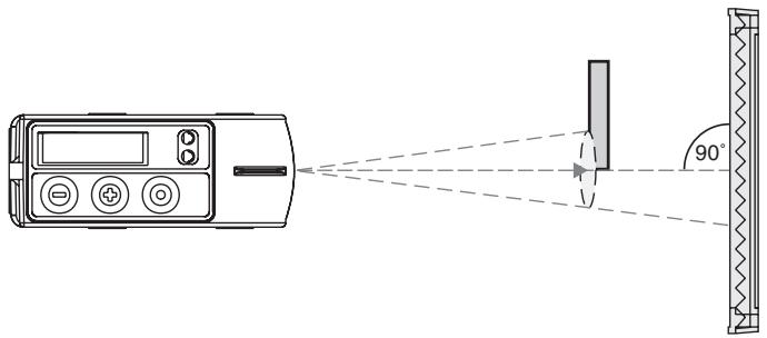
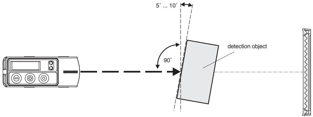
If the detection object has a glossy, reflecting surface, the object should be tilted by 5^ ... 10^ in relation to the surface of the light beam of the sensor.
If there is a reflecting surface in parallel with the sensor's optical axis, this might lead to unstable switching states. Therefore, reflecting objects within the sensor's optical axis should be avoided.
If this should not be possible, the reflecting surface should not be parallel to the sensor's optical axis, but should be rotated by about 10^ .
Mirror-like objects can cause malfunction inside and outside the sensing range. Avoid mirror-like objects in or close to the optical axis.
6-2-2 Assembly via assembly holes
- Professionally produce securing holes/threaded holes corresponding to the six possible assembly holes of the sensor (see Section 3-3 Dimensions).
- Professionally attach the sensor with suitable securing material.
- Roughly align the sensor to the possible position of the measured object.
- Tighten the securing screws.
6-2-3 Assembly by universal mounting bracket E39-EL1
- Drill and tap the necessary securing holes / threaded holes according to the required pattern of the universal mounting bracket (see 3-4 Dimensions).
- Using the included securing material, professionally fit the sensor on the mounting bracket.
- With suitable securing material, professionally fit the mounting bracket on the body of the machine.
- Roughly align the sensor to the possible position of the measured object.
- Tighten the securing screws.
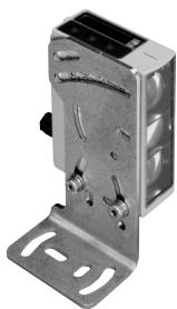
6-2-4 Assembly with adapter bracket E39-EL2 and bracket E39-EL1
Applying the adapter bracket E39-EL2 the universal mounting bracket E39-EL1 can be used as an adapter plate to mount the E3NT to existing holes.
- Mount the bracket E39-EL1 to the existing assembly holes on the machine, if necessary produce additional ones.
- Using the included securing material of the E39-EL1 professionally fit the sensor to the adapter bracket E39-EL2.
- Using the included securing material professionally fit the adapter bracket to the universal mounting bracket E39-EL1.
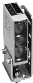
SECTION 7: Electrical Connection
7-1 Safety notes

Assembly, electrical connection and maintenance must only be carried out by instructed, trained and authorised specialist personnel in accordance with applicable regulations, after de-energising the power supply and with the machine switched off.
The machine must be safeguarded against reactivation.

Conversions and changes and tampering in the interior of the sensor, the data interface and the alignment tool are forbidden.

A technical data of the supply voltage and of the input/output wires must conform to the technical data of the sensor (see sensor rating plate and SECTION 3 Specification).

Do not lay the sensor's connecting leads in the direct proximity of cables carrying higher voltages or together with cables that switch inductive or capacitive loads.

A power supply unit that conforms to the necessary EMC requirements must be used.

The operating voltage must be within the applicable operating voltage range. Unstabilised full or halfwave rectifiers must not be used for the power supply.

The electrical connection must conform to EMC requirements.

The equipotent bonding system for the machine must be produced in conformity with EN 60204-1, Section 8 "Equipotential bonding".

Check the operability of all equipotential bonding conductors in conformity with Section 20 of EN 60204-1 before releasing the machine for operation.
7-2 Establishing electrical connection
- Establish electrical connection in conformity with the pin assignments described in SECTION 7-3 Connection diagrams.
- Professionally establish the equipotential bonding system, the protective earthing, the shielding and the sensor wiring in line with EMC requirements (see 7-4 Connection in line with EMC requirements).
7-3 Connection diagrams
7-3-1 Output circuits
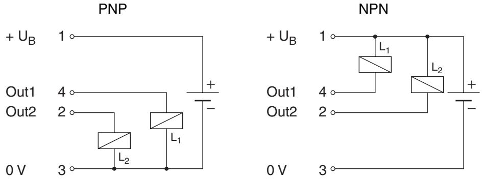
The sensor is factory set to a PNP output. The output circuit is resistant to short-circuits and reversed power supply.
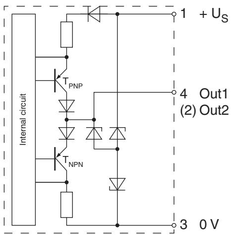
- When use is made of the PNP or NPN output circuit, the output circuit which has not been selected is deactivated.
- When used as a complementary output, NPN or PNP outputs act in antiphase as the switch state changes.
7-3-2 Input circuits
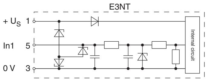
The sensor inputs are realized in positive logic and detect a positive voltage level of more than 1 ms duration as a valid signal if the voltage level is between 10V and the power supply voltage.
Pin 5 input circuit:
Pin 2 input circuit:
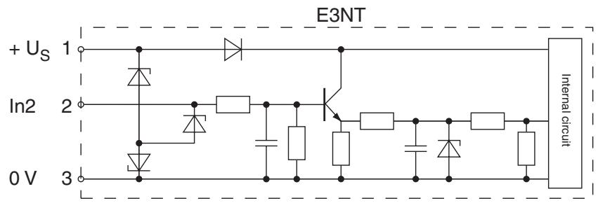

Pin 2 can be set as input or output (factory default)
7-3-3 Connector pin assignments
The sensor is connected by means of a standard 5-pole M12 connector. The pin assignment is depicted below with the view of connector pins on the sensor.
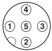
① +Us
OUT2/IN2
(3) 0 ~V
OUT1
⑤ IN 1
7-4 Connection in line with EMC requirements
To ensure stable functioning of the sensor the following precautions should be considered:
In environments with high interference levels, use cables with twisted-pair wires and/or shielded cables.
- When cables are introduced into an EMC control cabinet, guide the cable shield without interruption through the wall of the EMC control cabinet (e.g. via a cable conduit).
Professionally connect the cable shield to the control cabinet housing (flat surface, conductive).
- Professionally connect wires of cables or free cable ends that are not used to the cable shield on both ends of the cable.
- If the control cabinet is connected by means of connectors, use connectors with a metal housing and a leading protective earth contact (in accordance with EN 60204-1) only.
- Conductively connect the cable shield to the connector housing.
Professionally connect the mating connector to the control cabinet housing (flat surface, conductive).
- Route supply and signal leads in separate cable ducts.
- Route supply and signal leads as closely as possible to the equipotential bonding conductor.
- Do not route cable ducts in the proximity of strong electromagnetic interference sources such as electric motors or transformers.
- Suitable protective measures conforming to EN 60204-1 must be taken if the cable layout does not fully rule out the risk of lightning strikes.
SECTION 8: Setting into Operation
8-1 Safety notes

The retro-reflective sensors in the E3NT type series may only be used as described in these operating instructions. They may only be operated as part of a higher-level overall system, e.g. of a machine installation.

Retro-reflective sensors in the E3NT type series must not be used as safety components within the scope of the EU machine guideline. Their use is not permitted in applications in which the safety of persons depends on functioning of the sensor!
8-2 Switching on the operating voltage
After the operating voltage has been switched on, the sensor runs a power-on reset with a self-test.
The flashing display " ---- " appears in the event of a short-circuit at the outputs. The sensor continues normal functioning once the short-circuit at the outputs has been remedied.
8-3 Aligning the sensor
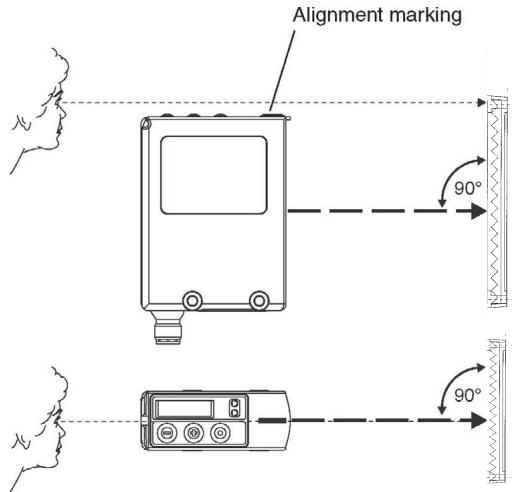
Hence the sensor must be aligned relative to the optical axis in direction of the retro-reflector. The alignment marking on the top of the sensor can be used as a sighting line for the optical axis, thus simplifying alignment.
- Position the measured object at the required position in front of the sensor.
- Undo the securing screws.
- Align the sensor's optical axis/alignment marking to the measured object.
- Tighten the securing screws.
- Check alignment once again.
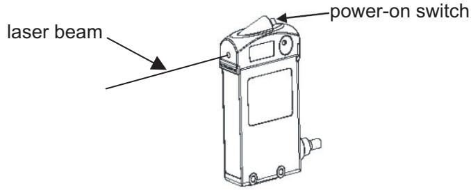
For alignment over long distances, the laser alignment aid (E3NT-AP1) can be used (order separately). This alignment aid can be clicked on top of the sensor and a visible laser beam gives a hint of the direction of the sensor.
SECTION 9: Configuration
9-1 Setting the sensor using the push buttons
The sensor is set by means of three push buttons. With these push buttons, the user navigates through the setting menus, through which all necessary sensor settings can be made.
If no keys are pressed for 2 minutes during set-up, the sensor returns automatically to run mode.
9-1-1 Display in the normal mode
Depending on the user set-up, the sensor's display shows the following in the run mode:
Status LED is turned off.
Digital display:
The current received light intensity is depicted in the bar chart.
The flashing display "----" appears in the event of a short-circuit at the outputs. The sensor continues normal functioning once the short-circuit at the outputs has been remedied.
9-1-2 Main menu structure
The following figure shows the structure of the main set-up menu.
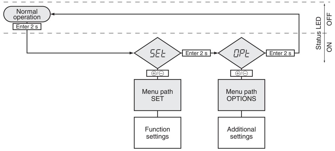
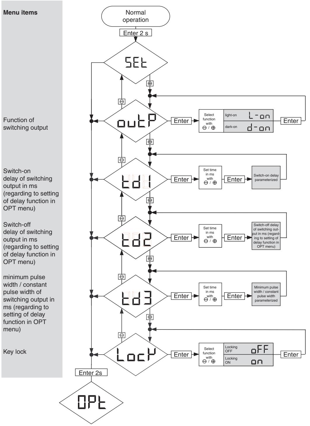
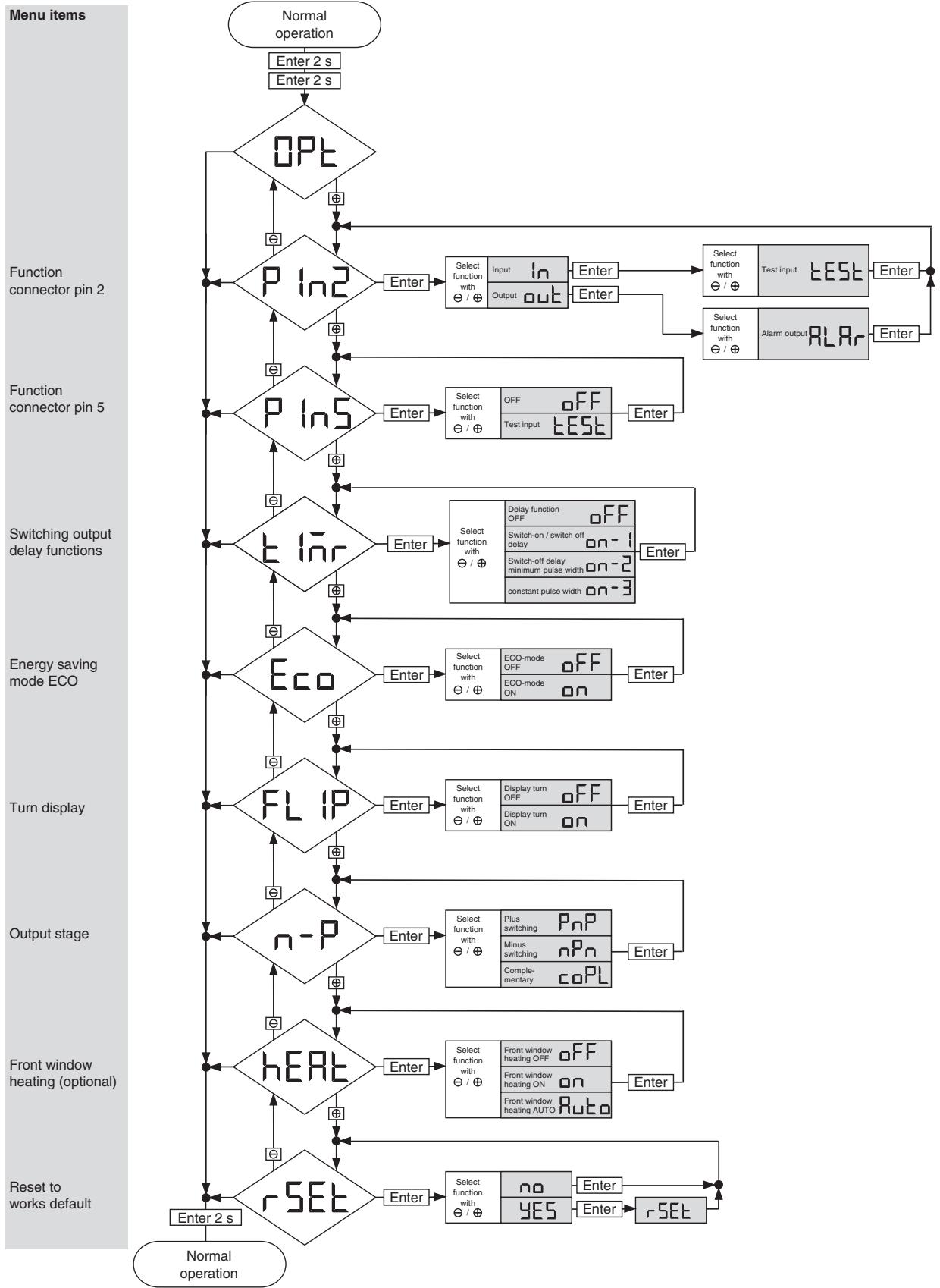
When the Enter key is pressed for 2 seconds, the sensor switches from the normal mode to the SET menu path. The sensor switches to each next menu path when the Enter key is repeatedly pressed for 2 seconds. If no key is pressed for more than 2 minutes, the sensor returns to the normal operation state.
In the menu paths, the required parameters can be selected by pressing the and keys.
- For Enter a parameter or a selection: Press the Enter key < 1 second.
- For switching to the next main menu point: Press the Enter key >2 second.
- To skip a menu path, you can also press the Enter key for 4 seconds.
9-1-3 SET menu path
All function parameters of the sensor are defined in the SET menu path. The Status LED is on.
Remarks
- If the delay-function is set to „off“ in the OPTIONS menu path, the switch-on/off delay parameters do not appear in the SET menu path.
- The On-delay-setting and the Off-delay-setting are only available if the switch-on/off delay in the OPTIONS menu path is set to "on-1".
- The output behaves depending on the switch delay function that is set in the OPTIONS menu path.
- The key lock becomes active again when no keys have been pressed for approx. 150 seconds. The key lock can be temporarily cancelled by pressing the and keys for 4 seconds.
9-1-4 OPTIONS menu path
All function options of the sensor are defined in the OPTIONS menu path. The Status LED is on.
Remarks
- If the ECO energy saving mode is on, the display is switched off if no keys are pressed for about 3 minutes. The display is switched on again when any key is pressed.
- The different modes for the switching output delay are described in chapter 4-3-4 Switch-on delay (page 17) and following
9-2 Setting the sensor with a PC
All parameters of the sensor can also be set with a PC and the OMRON SensorSupportSoftware S3. The connection between the sensor and the PC is established via an optical data interface (E3NT-AL232 2m). The data interface is clipped onto the sensor and should be connected to a free COM port on the PC/laptop via the interface cable.
Data communication with the PC can be used for the following functions:
- Sensor set-up and configurations
Real time readout of the object distance of switching states of the stability of the alarm outputs
Monitoring and archiving the sensor data - Updating the sensor firmware:
A newer or a customized version of the sensor's operating program can be transferred to the sensor. The power supply voltage must be 16Vmin for firmware update.
Refer to the separate operating instructions for further information on set-up with a PC and the SensorSupportSoftware S3.
SECTION 10: Maintenance and Repair
10-1 Maintenance

Assembly, electrical connection and maintenance may only be carried out by instructed, trained and authorized specialist personnel in accordance with applicable regulations, after de-energizing the power supply and with the machine switched off.
The machine must be safeguarded against reactivation.
Do not use any scratching or abrasive cleaning materials. The protective pane of the optical system might get damaged.
The sensor requires no maintenance. Remove dirt build up from the optical system and the display at regular intervals only with a soft, non-abrasive fabric. Residual dirt may have influence on the performance and the accuracy of the sensor.
10-2 Repair
The sensor, the optical data interface and the alignment tool may only be repaired by the manufacturer. Send in the sensor and the optical data interface tool to the supplier for repair along with a description of the fault.
SECTION 11: Accessories and Parts
| Description | Article number |
| Universal mounting bracket | E39-EL1 |
| Adapter bracket | E39-EL2 |
| Alignment bracket | E39-EL4 |
| Laser alignment aid | E3NT-AP1 |
| IR data interface, cable length 2 m | E3NT-AL232 2m |
| Straight cable socket, 5-pole, 2 m cable length | XS2F-D521-DG0-A |
| Straight cable socket, 5-pole, 5 m cable length | XS2F-D521-GG0-A |
| L-shaped cable socket, 5-pole 2 m cable length | XS2F-D522-DG0-A |
| L-shaped cable socket, 5-pole 5 m cable length | XS2F-D522-GG0-A |
| Retro-reflector round with diameter 8cm | E39-R7 |
| Retro-reflector square shape (10cm x 10cm) | E39-R8 |
| Retro-reflector rectangular shape (4cm x 6 cm) | E39-R1 |
| Retro-reflective adhesive tape (35 x 10 mm) | E39-RSA |
| Retro-reflective adhesive tape (40 x 35 mm) | E39-RSB |
Note: This selection represents the most commonly used accessories for this sensor. Other mounting brackets, cable sockets and reflectors are available. Please contact your OMRON sales representative for a complete overview of OMRON's sensor accessories.
- Retro-Reflective Sensor E3NT-R
- Photoelectric Sensor
- OPERATION MANUAL
- Table of Contents
- SECTION 1: Important Precautions. 3
- SECTION 2: Safety Notes. 5
- SECTION 3: Specification. 7
- SECTION 4: Function 15
- SECTION 5: Transport 21
- SECTION 6: Mechanical installation of the sensor 23
- SECTION 7: Electrical Connection 25
- SECTION 8: Setting into Operation 29
- SECTION 9: Configuration 31
- SECTION 10: Maintenance and Repair 35
- SECTION 11: Accessories and Parts 37
- SECTION 1: Important Precautions
- 1-1 Using the operating instructions
- 1-2 Use in accordance with the intended purpose
- 1-3 Use that is not in accordance with the intended purpose
- 1-4 Warranty and liability
- 1-5 Key to symbols
- 1-6 Abbreviations
- SECTION 2: Safety Notes
- 2-1 Safety notes
- SECTION 3: Specification
- 3-1 Specifications of Retro-reflective sensor E3NT-R_7
- 3-1-1 General data
- 3-1-2 Optical data
- 3-1-3 Mechanical data
- 3-1-4 Electrical data
- 3-2 Specifications of Optical data link E3NT-AL232 (order separately)
- 3-3 Specifications of Laser alignment aid E3NT-AP1(order separately)
- 3-4 Dimensions
- 3-4-1 Sensor E3NT-R17 and E3NT-RH17 (with horizontal connector)
- 3-4-2 Sensor E3NT-R37 and E3NT-RH37 (with vertical connector)
- 3-4-3 Universal mounting bracket E39-EL1 (order separately)
- 3-4-4 Adapter bracket E39-EL2 (order separately)
- 3-4-5 Optical data link E3NT-AL232 2m (order separately)
- 3-4-6 Alignment bracket E39-EL4 (order separately)
- 3-4-7 Laser alignment aid E3NT-AP1 (order separately)
- 3-4-8 Retroreflectors (order Separately)
- 3-4-8-1 E39-R7 (0 84 mm)
- 3-4-8-2 E39-R8 (100 mm x 100 mm)
- 3-4-8-3 E39-R40 (80 mm x 80 mm)
- 3-4-8-4 Adhesive tape E39-RS1
- 3-4-8-5 Adhesive tape E39-RS2
- 3-4-8-6 Adhesive tape E39-RS3
- SECTION 4: Function
- 4-1 Functions
- 4-2 Display and operator controls
- 4-2-1 LED display
- 4-2-2 LEDs
- 4-2-3 Push buttons on the sensor
- 4-2-4 Set-up via a PC
- 4-3 User set parameters
- 4-3-1 Output function
- 4-3-2 Output switching
- 4-3-3 Function of connector pin 2 and 5
- 4-3-4 Switch-on delay
- 4-3-5 Switch-off responses
- 4-3-6 Timing diagrams
- 4-3-7 Keyboard lock
- 4-3-8 ECO energy saving mode
- 4-3-9 Reset
- 4-4 Inputs/Outputs
- 4-4-1 Input: Test input TEST
- 4-4-2 Outputs
- 4-4-2-1 Switching output OUT
- 4-4-2-2 Alarm output ALARM
- SECTION 5: Transport
- 5-1 Packaging / Transportation damage
- 5-2 Storage
- 5-3 Scope of delivery
- SECTION 6: Mechanical installation of the sensor
- 6-1 Safety notes
- 6-2 Sensor assembly
- 6-2-1 Sensor's assembly direction
- 6-2-2 Assembly via assembly holes
- 6-2-3 Assembly by universal mounting bracket E39-EL1
- 6-2-4 Assembly with adapter bracket E39-EL2 and bracket E39-EL1
- SECTION 7: Electrical Connection
- 7-1 Safety notes
- 7-2 Establishing electrical connection
- 7-3 Connection diagrams
- 7-3-1 Output circuits
- 7-3-2 Input circuits
- 7-3-3 Connector pin assignments
- 7-4 Connection in line with EMC requirements
- SECTION 8: Setting into Operation
- 8-1 Safety notes
- 8-2 Switching on the operating voltage
- 8-3 Aligning the sensor
- SECTION 9: Configuration
- 9-1 Setting the sensor using the push buttons
- 9-1-1 Display in the normal mode
- 9-1-2 Main menu structure
- 9-1-3 SET menu path
- Remarks
- 9-1-4 OPTIONS menu path
- 9-2 Setting the sensor with a PC
- SECTION 10: Maintenance and Repair
- 10-1 Maintenance
- 10-2 Repair
Marque : OMRON
Modèle : E3NT-R
Catégorie : Capteur de proximité