
D4E-N - Capteur de proximité OMRON - Notice d'utilisation et mode d'emploi gratuit
Retrouvez gratuitement la notice de l'appareil D4E-N OMRON au format PDF.


| Type de produit | Capteur de proximité (interrupteur de fin de course scellé) |
| Marque | OMRON |
| Modèle | D4E-N |
| Poids | Environ 86 g (selon le modèle) |
| Protection | IP67 |
| Température de fonctionnement | -10 °C à 80 °C |
| Humidité de fonctionnement | 95% max. |
| Tension nominale | 250 VAC (max.) |
| Courant nominal (général) | 5 A à 125 VAC |
| Courant nominal (micro charge) | 0,1 A à 125 VAC / 30 VDC |
| Durée de vie mécanique | 10 000 000 opérations min. |
| Durée de vie électrique | 500 000 opérations min. (5 A, 250 VAC, charge résistive) |
| Rigidité diélectrique | 1 000 VAC (entre bornes), 1 500 VAC (entre parties métalliques) |
| Résistance d'isolement | 100 MΩ min. à 500 VDC |
| Résistance de contact | 15 mΩ max. (valeur initiale) |
| Fonctions principales | Détection de position, actionnement par came, commutation électrique |
| Entretien et nettoyage | Nettoyer avec un chiffon sec, éviter les solvants. Vérifier le serrage des vis. |
| Sécurité | Double isolation (classe II), protection IP67, fusible de protection recommandé |
| Pièces détachées et réparabilité | Connecteurs et câbles disponibles séparément (modèles XS2F). Pas de pièces réparables par l'utilisateur. |
| Informations générales | Interrupteur de fin de course scellé, compact et fiable. Convient aux environnements difficiles. |
FOIRE AUX QUESTIONS - D4E-N OMRON
Questions des utilisateurs sur D4E-N OMRON
0 question sur cet appareil. Repondez a celles que vous connaissez ou posez la votre.
Poser une nouvelle question sur cet appareil
Téléchargez la notice de votre Capteur de proximité au format PDF gratuitement ! Retrouvez votre notice D4E-N - OMRON et reprennez votre appareil électronique en main. Sur cette page sont publiés tous les documents nécessaires à l'utilisation de votre appareil D4E-N de la marque OMRON.
MODE D'EMPLOI D4E-N OMRON
Small Sealed Switch
D4E- □N
Slim and Compact Switch with Better Seal and Ensuring Longer Service Life than D4E
- Flat springs with an improved lever ratio of the built-in switch ensure smooth snap action and long life expectancy.
- Protection cover protects the built-in switch from dust and oil. Plunger incorporates a tough seal cap that lasts for a long time.
- One touch connector eliminates need for tedious wiring operations and reduces downtime for wiring and maintenance (models with standard, easy-to-use screw terminals are also available).
- Minute load model with gold cladding is optimal for electronic control.
- Molded terminal types as well as molded terminal types with operating indicator lamps are available for screw terminal systems.
- No difference in mounting pitch and characteristics between D4E- N and D4E models.
Model Number Structure
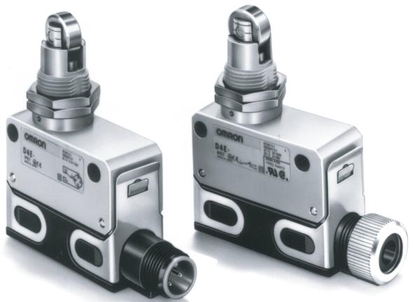
■ Model Number Legend
D4E-□□□□N 1234
1. Rated Current
1: 5 A at 125 VAC
(1 A at 125 VAC/30 VDC for model with a connector)
2: 0.1 A at 125 VAC
(0.1 A at 125 VAC/30 VDC for model with a connector)
2. Actuator
A: Roller plunger
B: Crossroller plunger
C: Plunger
D: Sealed roller plunger
E: Sealed crossroller plunger
F: Sealed plunger
G: Roller lever
H: One-way action roller lever
3. Terminals
00: AC connector
10: DC connector
20: Screw terminals without a cable
21: Screw terminals with a cable (right-hand)
22: Screw terminals with a cable (left-hand)
23: Molded terminals with a cable (right-hand)
24: Molded terminals with a cable (left-hand)
(Cable is S-FLEX VCTF 3 m)
4. Operation Indicator
L: Neon lamp (250 VAC)
L1: LED (12 VDC)
L2: LED (24 VDC)
L3: LED (48 VDC)
Note: 1. Only the molded terminal models can be equipped with an operation indicator.
2. Desired Switches may not be manufactured depending on the combination between molds and indicators. Contact our sales representative for further information.
■ List of Models
| Actuator | One-touch connector type | Screw terminal type | ||||
| General-purpose | Micro load | General-purpose without cable | Micro load without cable | General-purpose with cable | Micro load with cable | |
| Roller plunger | D4E-1A□0N | D4E-2A□0N | D4E-1A20N (see note 2) | D4E-2A20N | D4E-1A21N | D4E-2A21N |
| Crossroller plunger | D4E-1B□0N | D4E-2B□0N | D4E-1B20N (see note 2) | D4E-2B20N | D4E-1B21N | D4E-2B21N |
| Plunger | D4E-1C□0N | D4E-2C□0N | D4E-1C20N (see note 2) | D4E-2C20N | D4E-1C21N | D4E-2C21N |
| Sealed roller plunger | D4E-1D□0N | D4E-2D□0N | D4E-1D20N (see note 2) | D4E-2D20N | D4E-1D21N | D4E-2D21N |
| Sealed crossroller plunger | D4E-1E□0N | D4E-2E□0N | D4E-1E20N (see note 2) | D4E-2E20N | D4E-1E21N | D4E-2E21N |
| Sealed plunger | D4E-1F□0N | D4E-2F□0N | D4E-1F20N (see note 2) | D4E-2F20N | D4E-1F21N | D4E-2F21N |
| Roller lever | D4E-1G□0N | D4E-2G□0N | D4E-1G20N (see note 2) | D4E-2G20N | D4E-1G21N | D4E-2G21N |
| One-way action roller lever | D4E-1H□0N | D4E-2H□0N | D4E-1H20N (see note 2) | D4E-2H20N | D4E-1H21N | D4E-2H21N |
Note: 1. When ordering, specify the current type by replacing the blank box of the model number with 0 for AC connector or 1 for DC connector.
2. Approved by UL and CSA.
3. For the plunger and lever actuator models, the NC and NO terminal indicators are reversed.
4. Cold tolerance specifications are available for actuator models with an A, B, C, G, or H in the model number. When ordering, add C to the model number.
For example: D4E-1A20N D4E-1A20N-C
Accessories (Order Separately)
Plug
| Model | Current | Type | No. of conductors | Cable length | Applicable models |
| XS2F-A421-D90-A | AC | Straight | 4 | 2 m | D4E-☐☐00N |
| XS2F-A421-G90-A | 5 m | ||||
| XS2F-D421-D80A | DC | 2 m | D4E-☐☐10N | ||
| XS2F-D421-G80-A | 5 m |
■ Approved Standards
| Agency | Standard | File No. |
| UL | UL508 | E76675 |
| CSA | CSA C22.2 No. 14 | LR45746 |
| TÜV Rheinland | EN60947-5-1 | R9551015 |
■ Approved Standard Ratings UL, CSA
A300
| Voltage | Carry current | Current | Volt-amperes | ||
| Make | Break | Make | Break | ||
| 120 V | 10 A | 60 A | 6 A | 7,200 VA | 720 VA |
| 240 V | 30 A | 3 A | |||
TÜV (EN60947-5-1)
1G23LN D4E- I I I I IV
| Model | Applicable category and ratings | Thermal current (Ithe) | Indicator | |||
| I | II | III | IV | |||
| 1 | ☐ | 00 | AC-14 0.5 A/125 VAC | 5 A | --- | |
| 1 | ☐ | 10 | DC-12 0.5 A/30 VDC | 5 A | --- | |
| 1 | ☐ | 20, 21, 22 | AC-15 2A/250 VACDC-12 2A/48 VDC | 5 A | --- | |
| 1 | ☐ | 23, 24 | L | AC-15 2A/250 VAC | 5 A | Neon lamp |
| 1 | ☐ | 23, 24 | L1 | DC-12 2A/12 VDC | 5 A | LED |
| 1 | ☐ | 23, 24 | L2 | DC-12 2A/24 VDC | 5 A | LED |
| 1 | ☐ | 23, 24 | L3 | DC-12 2A/48 VDC | 5 A | LED |
| 2 | ☐ | 00 | AC-14 0.1A/125 VAC | 0.5 A | --- | |
| 2 | ☐ | 10 | DC-12 0.1A/30 VDC | 0.5 A | --- | |
| 2 | ☐ | 20, 21, 22 | AC-14 0.1A/125 VACDC-12 0.1A/48 VDC | 0.5 A | --- | |
| 2 | ☐ | 23, 24 | L | AC-14 0.1A/125 VAC | 0.5 A | Neon lamp |
| 2 | ☐ | 23, 24 | L1 | DC-12 0.1A/12 VDC | 0.5 A | LED |
| 2 | ☐ | 23, 24 | L2 | DC-12 0.1A/24 VDC | 0.5 A | LED |
| 2 | ☐ | 23, 24 | L3 | DC-12 0.1A/48 VDC | 0.5 A | LED |
Note: 1. : Actuator variation of item II
2. AC-14 0.5 A/125 VAC means as follows:
Applicable category: AC-14
Rated operating current (I_e) : 0.5 A
Rated operating voltage (U_e) : 125 VAC
Ratings
| Rated voltage | General-purpose | Micro load | ||||||||
| Non-inductive load | Inductive load | Non-inductive load | ||||||||
| Resistive load | Lamp load | Inductive load | Motor load | Resistive load | ||||||
| NC | NO | NC | NO | NC | NO | NC | NO | NC | NO | |
| 125 VAC | 5 (1) A | 1.5 (1) A | 3 (1) A | 2 (1) A | 1 (1) A | 0.1 A | ||||
| 250 VAC | 5 (1) A | 1.5 (1) A | 3 (1) A | 1 A | 0.5 A | --- | ||||
| 8 VDC | 5 (1) A | --- | 1.5 (1) A | --- | 0.1 A | |||||
| 14 VDC | 5 (1) A | --- | 1.5 (1) A | --- | 0.1 A | |||||
| 30 VDC | 5 (1) A | --- | 1.5 (1) A | --- | 0.1 A | |||||
| 125 VDC | 0.5 A | --- | 0.05 A | --- | --- | |||||
| 250 VDC | 0.25 A | --- | 0.03 A | --- | --- | |||||
| Inrush current | NC | 10 A max. |
| NO | 10 A max.. |
Note: 1. The above current ratings are for a standard current and the values in parentheses are for models with a connector.
2. Inductive loads have a power factor of 0.4 min. (AC) and a time constant of 7 ms max. (DC).
3. Lamp load has an inrush current of 10 times the steady-state current.
4. Motor load has an inrush current of 6 times the steady-state current.
Characteristics
| Degree of protection | IP67 |
| Durability (see note 3) | Mechanical: 10,000,000 operations min. Electrical: 500,000 operations min. (5 A at 250 VAC, resistive load) 5,000,000 operations min. (10 mA at 24 VDC, resistive load) |
| Operating speed | 0.1 mm to 0.5 m/sec |
| Operating frequency | Mechanical: 120 operations/min Electrical: 30 operations/min |
| Rated frequency | 50/60 Hz |
| Insulation resistance | 100 MΩ min. (at 500 VDC) |
| Contact resistance | 15 mΩ max. (initial value) |
| Dielectric strength | 1,000 VAC, 50/60 Hz for 1 min between terminals of same polarity 1,500 VAC, 50/60 Hz for 1 min/Uimp at 2.5 kV (EN60947-5-1) between current-carrying metal parts and ground, and between each terminal and non-current-carrying metal part |
| Rated insulation voltage (Ui) | 250 VAC |
| Switching overvoltage | 1,000 VAC max. (EN60947-5-1) |
| Pollution degree (operating environment) | 3 (EN60947-5-1) |
| Short-circuit protective device (SCPD) | 10 A fuse (type gG or gl, IEC269 approved) |
| Conditional short-circuit current | 100 A (EN60947-5-1) |
| Conventional enclosed thermal current (Ithe) | 5 A (EN60947-5-1) |
| Protection against electric shock | Class II (grounding not required with double insulation) |
| Vibration resistance | Malfunction: 10 to 55 Hz, 1.5-mm double amplitude |
| Shock resistance | Destruction: 1,000 m/s² min. Malfunction: 300 m/s² min. |
| Ambient temperature | Operating: -10°C to 80°C (with no icing) |
| Ambient humidity | Operating: 95% max. |
| Weight | Approx. 86 g (in case of roller plunger) |
Note: 1. The above values are initial values.
2. The above ratings may vary depending on the model. Contact your OMRON representative for further details.
3. Durability values are calculated at an operating temperature of 5^ to 35^ , and an operating humidity of 40% to 70% . Contact your OMRON sales representative for more detailed information on other operating environments.
■Operating Characteristics
| Model | D4E-1A□□N D4E-2A□□N | D4E-1B□□N D4E-2B□□N | D4E-1C□□N D4E-2C□□N | D4E-1D□□N D4E-2D□□N | D4E-1E□□N D4E-2E□□N |
| OF max. | 11.77 N | 11.77 N | 11.77 N | 11.77 N | 11.77 N |
| RF min. | 4.90 N | 4.90 N | 4.90 N | 4.90 N | 4.90 N |
| PT max. | 1.5 mm | 1.5 mm | 1.5 mm | 1.5 mm | 1.5 mm |
| OT min. | 3 mm | 3 mm | 3 mm | 3 mm | 3 mm |
| MD(reference value) | (0.1 mm) | (0.1 mm) | (0.1 mm) | (0.1 mm) | (0.1 mm) |
| OP | 31.4±0.8 mm | 31.4±0.8 mm | 25.4±0.8 mm | 41.3±0.8 mm | 41.3±0.8 mm |
| Model | D4E-1F□□N D4E-2F□□N | D4E-1G□□N D4E-2G□□N | D4E-1H□□N D4E-2H□□N |
| OF max. | 11.77 N | 3.92 N | 3.92 N |
| RF min. | 4.90 N | 0.78 N | 0.78 N |
| PT max. | 1.5 mm | 2 mm | 2 mm |
| OT min. | 3 mm | 4 mm | 4 mm |
| MD(reference value) | (0.1 mm) | (0.3 mm) | (0.3 mm) |
| OP | 30±0.8 mm | 23.1±0.8 mm | 34.3±0.8 mm |
Note: The values given in parentheses are reference values.
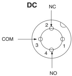
■ Contact Form
Screw Terminal Type Plunger
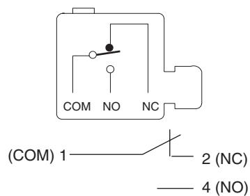
EN60947-5-1
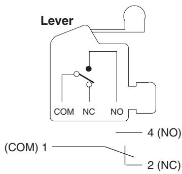
EN60947-5-1
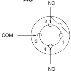
Connector Type AC
Engineering Data
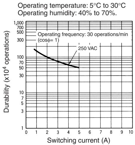
Electrical Durability (cosφ=1)
Nomenclature
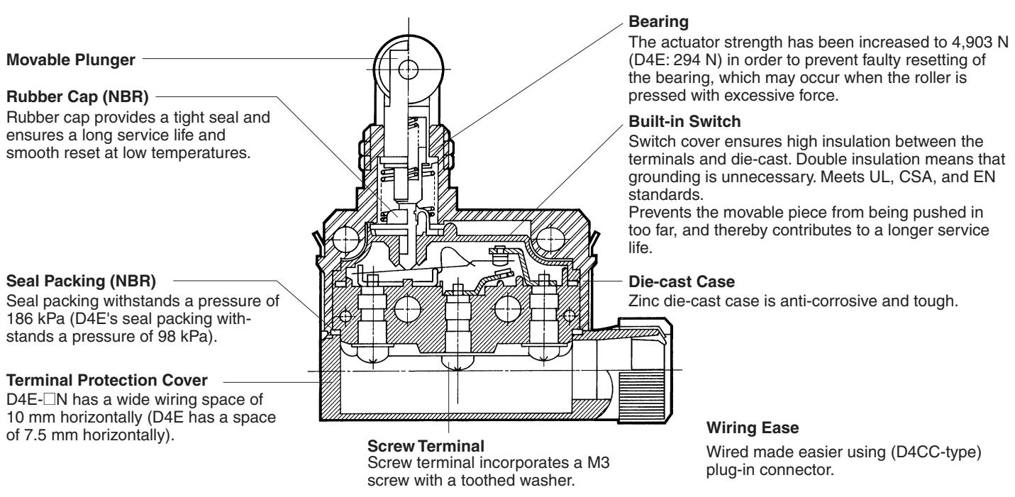
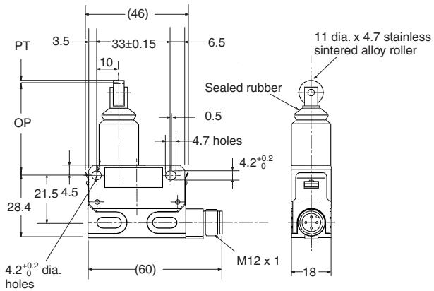
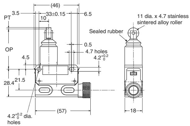
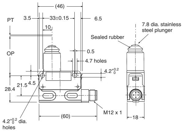
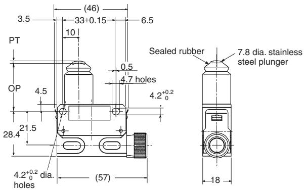
Note: 1. All units are in millimeters unless otherwise indicated.
2. Unless otherwise specified, a tolerance of ± 0.4mm applies to all dimensions.
3. A 3-m lead wire cable equivalent to the 3-conductor VCTF S-FLEX cable (0.75 mm², 7 mm in dia.) is provided.
4. A 5.8- to 7.6-dia. cable can be applied to the seal rubber for the lead wire outlet.
Roller Plunger
D4E-1A00N
D4E-1A10N
D4E-2A00N
D4E-2A10N
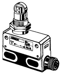
Roller Plunger
D4E-1A20N (See note 4.)
D4E-2A20N (See note 4.)
D4E-1A21N (See note 3.)
D4E-2A21N (See note 3.)
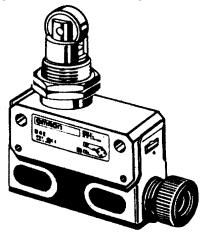
Cross Roller Plunger
D4E-1B00N
D4E-1B10N
D4E-2B00N
D4E-2B10N
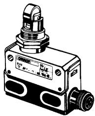
Cross Roller Plunger
D4E-1B20N
D4E-2B20N
D4E-1B21N
D4E-2B21N
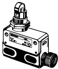
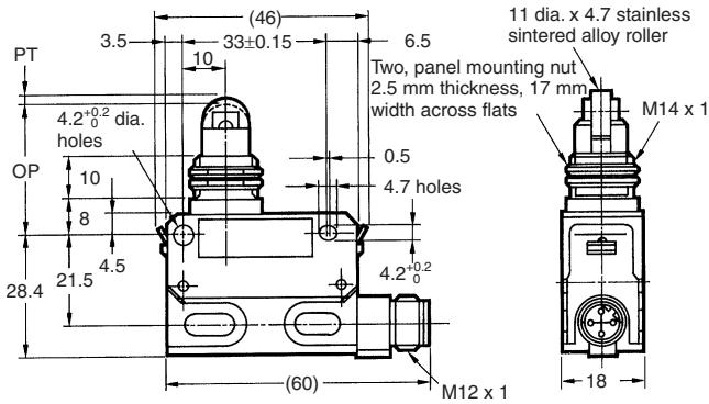
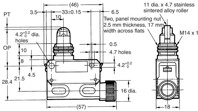
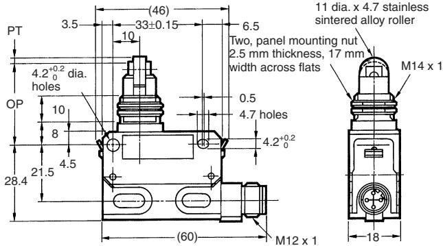
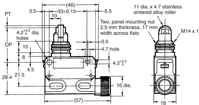
Plunger
D4E-1C00N
D4E-1C10N
D4E-2C00N
D4E-2C10N
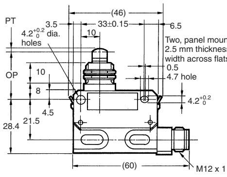
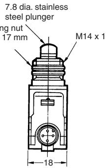
Plunger
D4E-1C20N (See note 4.)
D4E-2C20N (See note 4.)
D4E-1C21N (See note 3.)
D4E-2C21N (See note 3.)
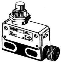
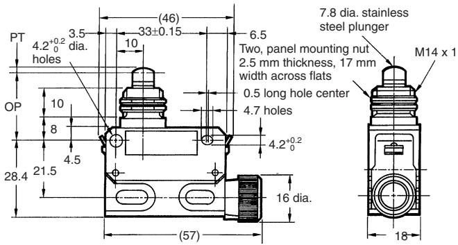
Sealed Roller Plunger
D4E-1D00N
D4E-1D10N
D4E-2D00N
D4E-2D10N
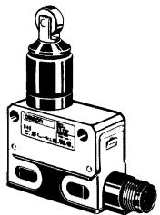
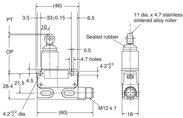
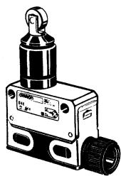
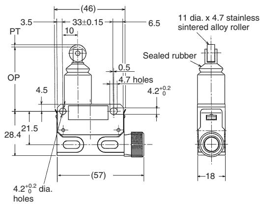
Sealed Roller Plunger
D4E-1D20N (See note 4.)
D4E-2D20N (See note 4.)
D4E-1D21N (See note 3.)
D4E-2D21N (See note 3.)
Sealed Cross Roller Plunger
D4E-1E00N
D4E-1E10N
D4E-2E00N
D4E-2E10N
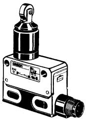
Sealed Cross Roller Plunger
D4E-1E20N (See note 4.)
D4E-2E20N (See note 4.)
D4E-1E21N (See note 3.)
D4E-2E21N (See note 3.)
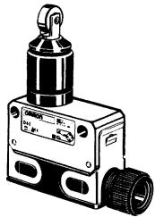
Sealed Plunger
D4E-1F00N
D4E-1F10N
D4E-2F00N
D4E-2F10N
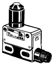
Sealed Plunger
D4E-1F20N (See note 4.)
D4E-2F20N (See note 4.)
D4E-1F21N (See note 3.)
D4E-2F21N (See note 3.)
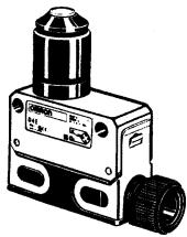
Roller Lever
D4E-1G00N
D4E-1G10N
D4E-2G00N
D4E-2G10N
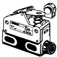
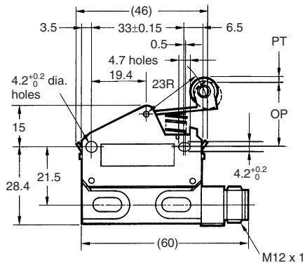
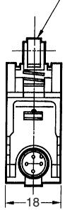
9.5 dia. x 4.8 stainless sintered alloy roller
Roller Lever
D4E-1G20N (See note 4.)
D4E-2G20N (See note 4.)
D4E-1G21N (See note 3.)
D4E-2G21N (See note 3.)
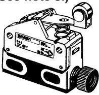
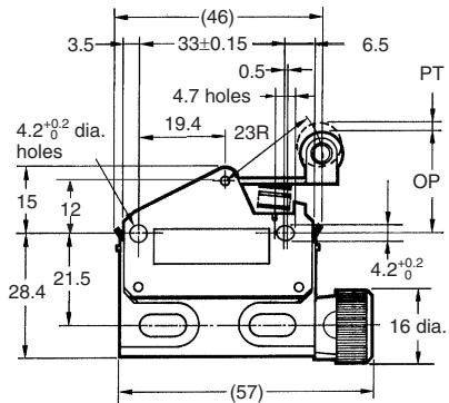
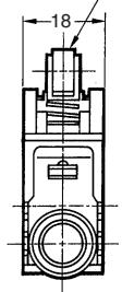
9.5 dia. x 4.8 stainless sintered alloy roller
One-way Action Roller Lever
D4E-1H00N
D4E-1H10N
D4E-2H00N
D4E-2H10N
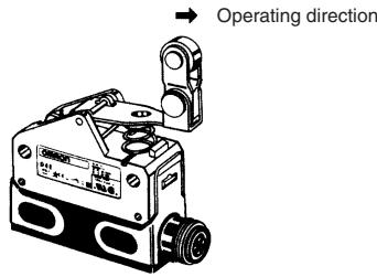
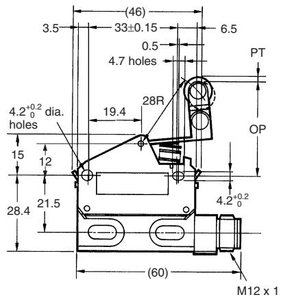
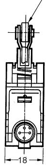
9.5 dia. x 4.8 stainless sintered alloy roller
One-way Action Roller Lever
D4E-1H20N (See note 4.)
D4E-2H20N (See note 4.)
D4E-1H21N (See note 3.)
D4E-2H21N (See note 3.)
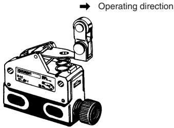
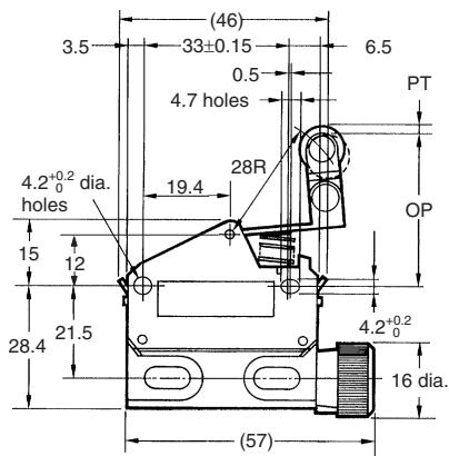
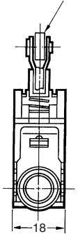
9.5 dia. x 4.8 stainless sintered alloy roller
■ Molded Terminal Models
The molded-terminal model is available with right-hand, left-hand and underside leads and is recommended for use where the Switch is exposed to dust, oil or moisture. It can be used like a screw-terminal model (with a cable), and the dimensions and operating characteristics are the same as for standard models.
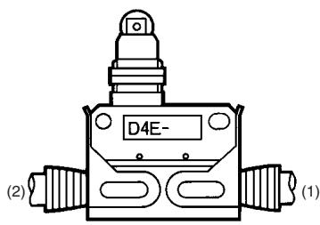
Example:
Standard type:
D4E-1A20N
Location of lead output:
Right-hand D4E-1A23N
Suffix by Location of Lead Outlet
| Location of lead output | Suffix for pre-wired terminal |
| COM, NC, NO | |
| (1) Right-hand | D4E-☐☐23N |
| (2) Left-hand | D4E-☐☐24N |
Lead Supplies
| Leads | Nominal cross-sectional area | Finished outside diameter | Terminal connections | Standard length |
| V.C.T.F. S-FLEX (vinyl cabtire coat) | 0.75 mm² | 3 conductors | Black: COM | 3 m |
| 7 mm dia. | White: NO Red: NC |
Comparison between Old and New Mold Terminal Models
The D4E-N and D4E are different from each other in terminal specifications.
| Location of lead output | D4E-N | D4E |
| Right-hand | D4E-☐☐23N | D4E-☐☐21 |
| Left-hand | D4E-☐☐24N | D4E-☐☐23 |
| Underside | --- | D4E-☐☐22 |
■ Operation of Indicator-equipped Models
The operation indicator is designed to illuminate when the Switch is not operating. (Because of the molded terminal model, any change to the Switch wiring cannot be made.)
AC Operation
A neon lamp indicator is provided.
The operating voltage is 90 to 250 VAC.
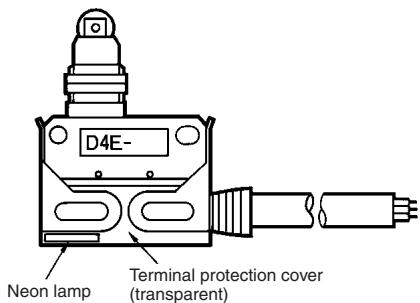
There is no difference in operating characteristics between D4E AC Models and corresponding D4E Standard Models.
There is no difference in dimensions between D4E AC Models and D4E Standard Models.
Example:
Basic type: D4E-1A23N
When placing your order for the molded terminal model with an neon lamp operation indicator, specify the model number as D4E-1A23LN.
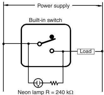
Internal Circuit
DC Operation
LED indicator is provided.
As a rectifier stack is incorporated, into the unit and no directionality exists for connection of + and - , this type can also be operated on AC.
Voltage ratings of LED indicators are as shown in the table below.
Internal Circuit
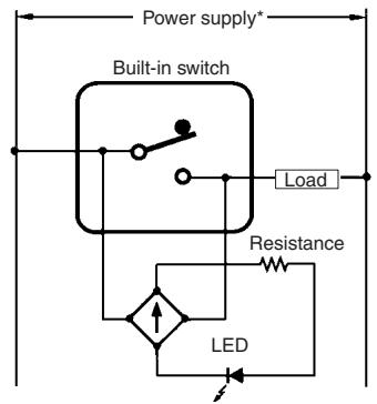
Note: *An external 24VDC power supply can be used, eg. OMRON S8VS.
| Type | Voltage rating | Lamp current | Internal resistance |
| L1 | 12 V | Approx. 2.4 mA | 4.3 kΩ |
| L2 | 24 V | Approx. 1.2 mA | 18 kΩ |
| L3 | 48 V | Approx. 2.1 mA | 22 kΩ |
Example:
When ordering a D4E DC Model, add the following suffix to the model number.
Basic Model: The model number of the D4E-1A23N with a built-in 12-V LED indicator is D4E-1A23L1N.
Refer to the Technical Information for Limit Switches (Cat. No. C121).
Correct Use
Do not solder the screw terminals.
Sealing materials may deteriorate when used outdoors or when exposed to cutting oil, solvents, or chemicals. Check this on actual equipment and, if deterioration is foreseen, consult your OMRON representative in advance.
If the one-touch connector is to be mounted onto the switch body, lightly push up the fitting so that the switch body can then be inserted into the clamp.
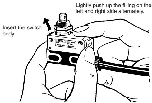
Be sure that the clamp is inserted to the full depth, because the Switch will not function properly if one of the clamps is improperly inserted.
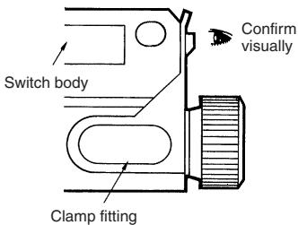
If the clamp is properly inserted up to the full depth, it will not slide out easily. Be sure to carefully confirm all the above items.
Be sure to connect a fuse with a breaking current 1.5 to 2 times the rated current to the Limit Switch in series in order to protect the Limit Switch from damage due to short-circuiting.
When using the Limit under the EN ratings, use a gl or gG 10-A fuse that conforms to IEC260.
Mounting
Secure the Switch with two M4 screws and washers. The tightening torque applied to each terminal must be 1.18 to 1.37N· m . Tighten the screws to the specified torque. An excessive tightening torque may damage the Switch and cause a malfunction.
Mounting Holes
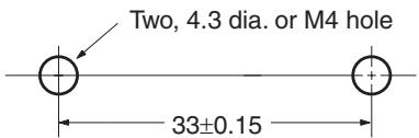
When mounting the panel mount-type Switch with screws on a side surface, remove the hexagonal nuts from the actuator.
When mounting the panel mount type on a panel, tighten the hexagonal nuts of the actuator to a torque less than 7.85 N·m.
Mounting Hole
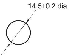
Operating method, shape of cam or dog, operating frequency, and the overtravel (OT) have significant effect on the service life and precision of the Limit Switch. Make sure that the shape of the cam is smooth enough.
Check that OT has a sufficient margin. The actual OT should be rated OT × 0.7 to 1.
Do not change the operating position by remodeling the actuator.
Wiring
When wiring screw terminals, M3-size round solderless terminals with an insulation tube is recommended. The conductor size should be 0.75mm^2 and cable diameter should be 7mm .
Refer to the following when wiring.
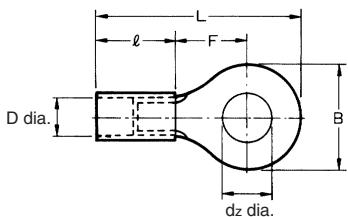
dz dia.: 3.2
D dia.: 1.9
B: 5.2
L: 16.4
F: 5.8
l: 8.0 (mm)
Wiring Method
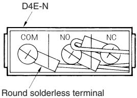
Tightening Torque
A loose screw may result in a malfunction. Be sure to tighten each screw to the proper tightening torque as shown below.
| No. | Type | Torque |
| 1 | Terminal screw (M3) | 0.24 to 0.44 N·m |
| 2 | Switch mounting screw (M4) | 1.18 to 1.37 N·m |
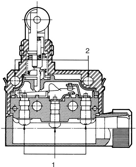
ALL DIMENSIONS SHOWN ARE IN MILLIMETERS.
To convert millimeters into inches, multiply by 0.03937. To convert grams into ounces, multiply by 0.03527.
Cat. No. C028-E1-05
In the interest of product improvement, specifications are subject to change without notice.
- Small Sealed Switch
- D4E- □N
- Slim and Compact Switch with Better Seal and Ensuring Longer Service Life than D4E
- Model Number Structure
- ■ Model Number Legend
- D4E-□□□□N 1234
- Rated Current
- Actuator
- Terminals
- Operation Indicator
- ■ List of Models
- Accessories (Order Separately)
- ■ Approved Standards
- ■ Approved Standard Ratings UL, CSA
- TÜV (EN60947-5-1)
- ■ Contact Form
- Engineering Data
- Nomenclature
- Plunger
- Sealed Roller Plunger
- Sealed Cross Roller Plunger
- Sealed Plunger
- Roller Lever
- One-way Action Roller Lever
- ■ Molded Terminal Models
- Comparison between Old and New Mold Terminal Models
- ■ Operation of Indicator-equipped Models
- AC Operation
- DC Operation
- Example:
- Correct Use
- Mounting
- Mounting Holes
- Mounting Hole
- Wiring
- Wiring Method
- Tightening Torque
Marque : OMRON
Modèle : D4E-N
Catégorie : Capteur de proximité