
D4BS - Capteurs de proximité OMRON - Notice d'utilisation et mode d'emploi gratuit
Retrouvez gratuitement la notice de l'appareil D4BS OMRON au format PDF.


| Type de produit | Interrupteur de sécurité à clé (Safety-door Switch) |
| Marque | OMRON |
| Modèle | D4BS |
| Indice de protection | IP67 (EN60947-5-1) |
| Température ambiante de fonctionnement | -40°C à 80°C (sans givre) |
| Humidité ambiante de fonctionnement | 95% max. |
| Matériau du boîtier | Plastique (selon normes IP67) |
| Poids | Environ 285 g (modèle D4BS-15FS) |
| Dimensions (interrupteur 1 conduit, ex. D4BS-15FS) | Environ 77 x 60 x 41 mm (voir notice détaillée) |
| Configuration des contacts | 1NC/1NO ou 2NC (selon modèle), avec mécanisme d'ouverture directe |
| Courant assigné | 10 A (UL/CSA, 600 VAC) ; 2 A (AC-15, 400 V) |
| Force d'insertion/extraction de la clé | 19,61 N max. |
| Course d'ouverture directe | 20 mm min. |
| Vitesse de fonctionnement | 0,1 m/s à 0,5 m/s |
| Fréquence de fonctionnement | 30 opérations/min max. |
| Résistance d'isolement | 100 MΩ min. (500 VCC) |
| Résistance de contact | 25 mΩ max. (valeur initiale) |
| Tension d'isolement assignée (Ui) | 600 V |
| Endurance mécanique | 1 000 000 opérations min. |
| Endurance électrique | 500 000 opérations min. (10 A, 250 VAC, charge résistive) |
| Section de câble recommandée | AWG20 à AWG14 (0,5 à 2,5 mm²) |
| Couple de serrage des vis de bornes | 0,59 à 0,78 N·m |
| Fixation | Par vis M5 (couple 4,90 à 5,88 N·m pour vis à tête hexagonale) |
| Entretien et nettoyage | Ne pas démonter l'interrupteur ; nettoyer avec un chiffon sec ; ne pas utiliser de solvants |
| Pièces détachées | Clés de fonctionnement (D4BS-K1, K2, K3) disponibles séparément ; autres pièces : contacter le fabricant de l'équipement |
| Réparabilité | L'utilisateur ne doit pas réparer l'interrupteur ; contacter le fabricant de l'équipement |
| Homologations | TÜV Rheinland, UL, CSA, BIA, SUVA ; conforme aux directives CE (Machines, Basse Tension) |
FOIRE AUX QUESTIONS - D4BS OMRON
Attention : ne pas utiliser l'interrupteur comme butée ; installez une butée séparée.
Questions des utilisateurs sur D4BS OMRON
0 question sur cet appareil. Repondez a celles que vous connaissez ou posez la votre.
Poser une nouvelle question sur cet appareil
Téléchargez la notice de votre Capteurs de proximité au format PDF gratuitement ! Retrouvez votre notice D4BS - OMRON et reprennez votre appareil électronique en main. Sur cette page sont publiés tous les documents nécessaires à l'utilisation de votre appareil D4BS de la marque OMRON.
MODE D'EMPLOI D4BS OMRON
Safety-door Switch
D4BS
Safety-door Switch's Special Operation Key Directly Pulls Apart the Contacts from Each Other and Contributes to the Safety of the Production Site
- Conforms to EN (TÜV) standards corresponding to the CE marking.
- Approved by UL, CSA, BIA, and SUVA standards.
- The switch contact is opened by a direct opening mechanism (NC contacts only) when the protective cover is opened. The EN-approved direct opening mechanism is indicated by on the Switch.
- Degree of protection of the switch box: IP67 (EN60947-5-1).
- Series includes models with gold-plated contacts for handling the micro-load range.
• Metric conduit types available.
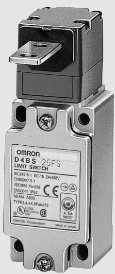
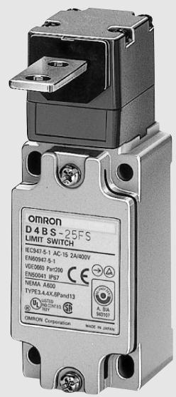




Model Number Structure
Model Number Legend
Switch
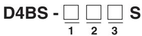
1. Conduit
1: PG13.5 (1 conduit)
2: G1/2 (1 conduit)
3: 1/2-14NPT (1 conduit)
4: M20
5: PG13.5 (3-conduit)
6: G1/2 (3-conduit)
7: 1/2-14NPT (3-conduit)
8: M20 (3-conduit)
2. Built-in Switch
5: 1NC/1NO (slow-action)
6: 1NC/NO (slow-action), gold-plated contacts
A: 2NC (slow-action)
B: 2NC (slow-action), gold-plated contacts
3. Head Mounting Direction
F: Four mounting directions possible (front-side mounting at shipping)
Operation Key

1
1. Operation Key Type
1: Horizontal mounting
2: Vertical mounting
3: Adjustable mounting (Horizontal)
Ordering Information
List of Models
Switches
| Type | Mounting direction | Conduit size | 1NC/1NO(Slow-action) | 2NC (Slow-action) | |
| 1-conduit | Front-side mounting | [AOHA] | Pg13.5 | D4BS-15FS | D4BS-1AFS |
| G1/2 | D4BS-25FS | D4BS-2AFS | |||
| M20 | D4BS-45FS | D4BS-4AFS | |||
| 3-conduit | [52KZ] | Pg13.5 | D4BS-55FS | D4BS-5AFS | |
| G1/2 | D4BS-65FS | D4BS-6AFS | |||
| M20 | D4BS-85FS | D4BS-8AFS | |||
Preferred stock item
Operation Keys (Order Separately)
| Type | Model |
Horizontal mounting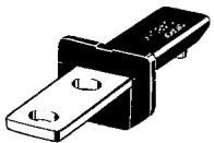 | D4BS-K1 |
Vertical mounting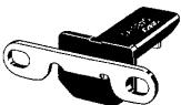 | D4BS-K2 |
Adjustable mounting (Horizontal)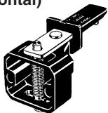 | D4BS-K3 |
Specifications
Approved Standards
| Agency | Standard | File No. |
| TÜV Rheinland | EN60947-5-1 | R9351022(Direct opening: approved) |
| UL | UL508 | E76675 |
| CSA | CSA C22.2 No. 14 | LR45746 |
| BIA | GS-ET-15 | 9303323 |
| SUVA | SUVA | E6187.d |
Standards and EC Directives
Conforms to the following EC Directives:
Machinery Directive
Low Voltage Directive
EN50041
EN1088
Approved Standard Ratings
TÜV (EN60947-5-1)
| Utilization category | AC-15 |
| Rated operating current (Ie) | 2 A |
| Rated operating voltage (Ue) | 400 V |
Note: Use a 10-A fuse type a gl or gG that conforms to IEC269 as a short-circuit protection device.
UL/CSA (UL508, CSA C22.2 No. 14)
A600
| Rated voltage | Carry current | Current | Volt-amperes | ||
| Make | Break | Make | Break | ||
| 120 VAC | 10 A | 60 A | 6 A | 7,200 VA | 720 VA |
| 240 VAC | 30 A | 3 A | |||
| 480 VAC | 15 A | 1.5 A | |||
| 600 VAC | 12 A | 1.2 A | |||
Characteristics
| Degree of protection (see note 2) | IP67 (EN60947-5-1) |
| Durability (see note 3) | Mechanical:1,000,000 operations min.Electrical:500,000 operations min. (10 A at 250 VAC, resistive load) |
| Operating speed | 0.1 m/s to 0.5 m/s |
| Operating frequency | 30 operations/min max. |
| Rated frequency | 50/60 Hz |
| Contact gap | 2 x 2 mm min. |
| Direct opening force (see note 4) | 19.61 N min. (EN60947-5-1) |
| Direct opening travel (see note 4) | 20 mm min. (EN60947-5-1) |
| Full stroke | 23 mm min. |
| Insulation resistance | 100 MΩ min. (at 500 VDC) between terminals of same or different polarity, between each terminal and ground, and between each terminal and non-current-carrying metal part |
| Contact resistance | 25 mΩ max. (initial value) |
| Rated insulation voltage (Ui) | 600 V (EN60947-5-1) |
| Conventional enclosed thermal current (Ithe) | 20 A (EN60947-5-1) |
| Dielectric strength (Uimp) | Impulse dielectric strength (Uimp) 4 kV (EN60947-5-1) between terminals of same or different polarity, between current-carrying metal parts and ground, and between each terminal and non-current-carrying metal part |
| Switching overvoltage | 1,500 V max. (EN60947-5-1) |
| Conditional short-circuit current | 100 A (EN60947-5-1) |
| Pollution degree (operating environment) | 3 (EN60947-5-1) |
| Insulation class | Class I (with ground terminal) |
| Vibration resistance | Malfunction: 10 to 500 Hz, 0.65-mm single amplitude |
| Shock resistance | Destruction:1,000 m/s2 min. (IEC68-2-27)Malfunction:300 m/s2 min. (IEC68-2-27) |
| Ambient temperature | Operating:-40°C to 80°C (with no icing) |
| Ambient humidity | Operating:95% max. |
| Weight | Approx. 285 g (in the case of D4BS-15FS) |
Note: 1. The above values are initial values.
2. Although the switch box is protected from dust, oil, or water penetration, do not use the D4BS in places where dust, oil, water, or chemicals may penetrate through the key hole on the head, otherwise Switch damage or malfunctioning may occur.
3. The durability is for an ambient temperature of 5^ C to 35^ C and an ambient humidity of 40% to 70%. Contact your OMRON sales representative for more detailed information on other operating environments.
4. These figures are minimum requirements for safe operation.
Contact Form (Diagrams Show State with Key Inserted)
| Model | Contact form | Diagram | Remarks | |
| D4BS-□5□S | 1NC/1NO | 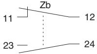 | 11 - 1223 - 24 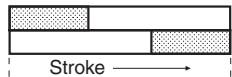 ONOperation Key insertion completion position ONOperation Key insertion completion position | Only NC contact 11-12 has an approved direct opening mechanism. ➕ Terminals 11-12 and 23-24 can be used as unlike poles. |
| D4BS-□A□S | 2NC |  | 11 - 1221 - 22 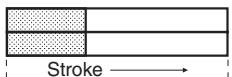 ONOperation Key insertion completion position ONOperation Key insertion completion position | NC contacts 11-12 and 21-22 have an approved direct opening mechanism. ➕ Terminals 11-12 and 21-22 can be used as unlike poles. |
Note: The terminal numbers are in accordance with EN50013, and the contact symbols are in accordance with IEC947-5-1.
Operation Key
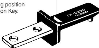
D4BS's exclusive-use Operation Key is provided to assure accurate switching operation.
Set Zone Mark
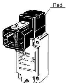
A triangular Set Zone Mark makes it easy to adjust the operating position when inserting the Operation Key.
Head
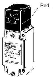
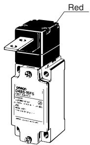
The switch head is coated with easy-to-see red paint. The mounting direction of the switch head can be varied to any of the four directions.
Seal Ring (NBR)
Oil Seal (NBR)
The operation plunger employs an oil seal, with which the switch box meets the requirements of IP67 (the sealing capability of the Operation Key's insertion mouth is IP00).
Seal Packing (NBR)
Conduit Opening
Available in four different types of conduit threads: Pg 13.5, G1/2, or 1/2-14NPT, M20.
Built-in Switch
A shearing force contact separating mechanism (NC contact) is employed, which positively pulls apart the contacts from each other by using shearing force if any abnormality such as contact welding should occur in the contact area.
There is a difference in level between the NC and NO terminal, which assures easy wiring.
Ground Terminal Screw
A ground terminal is provided to improve safety. (Built into the Unit.)
Dimensions
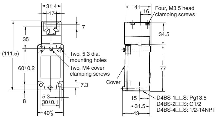
Note: 1. All units are in millimeters unless otherwise indicated.
- Unless otherwise specified, a tolerance of ±0.4 mm applies to all dimensions.
- The conduit thread varies with the model as follows:.
| Conduit thread | Model |
| Pg 13.5 | D4BS-1 S, D4BS-5 S |
| G1/2 | D4BS-2 S, D4BS-6 S |
| M20 | D4BS-4 S, D4BS-8 S |
Switches
1-conduit
D4BS-1□□S
D4BS-2□□S
D4BS-4□□S
| Operating characteristics | D4BS-1□□SD4BS-2□□SD4BS-4□□S |
| Key insertion force | 19.61 N max. |
| Key extraction force | 19.61 N max. |
| Pretravel (PT) | 10±5 mm |
| Direct opening force | 19.61 N min. |
| Direct opening stroke | 20 mm min. |
3-conduit
D4BS-5□□S
D4BS-6□□S
D4BS-8□□S

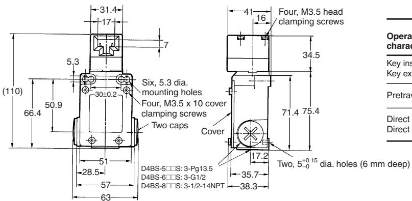
| Operating characteristics | D4BS-5□□SD4BS-6□□SD4BS-8□□S |
| Key insertion force | 19.61 N max. |
| Key extraction force | 19.61 N max. |
| Pretravel (PT) | 10±5 mm |
| Direct opening force | 19.61 N min. |
| Direct opening stroke | 20 mm min. |
Operation Keys
D4BS-K1
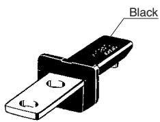
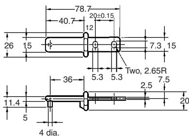
D4BS-K2
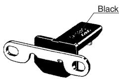
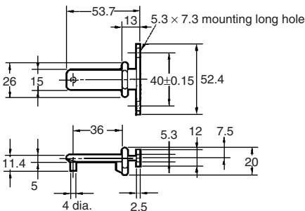
D4BS-K3
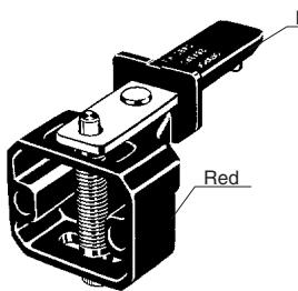
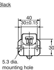
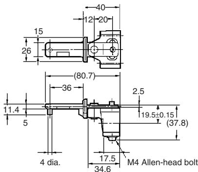
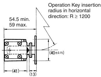
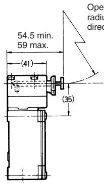
With Operation Key Inserted
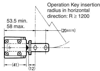
Horizontal Mounting
D4BS-1□□S +D4BS-K1
D4BS-2□□S +D4BS-K1
D4BS-4□□S +D4BS-K1
Vertical Mounting
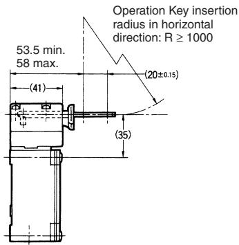
D4BS-1□□S +D4BS-K2
D4BS-2□□S +D4BS-K2
D4BS-4□□S +D4BS-K2
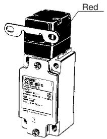
Adjustable Mounting (Horizontal)
D4BS-1□□S +D4BS-K3
D4BS-2□□S +D4BS-K3
D4BS-4□□S +D4BS-K3
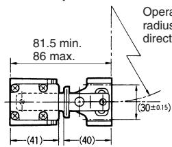
Operation Key insertion radius in horizontal direction: R ≥ 150
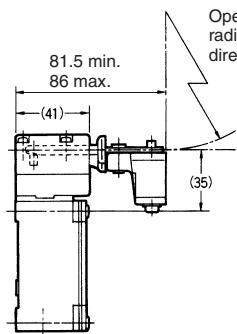
Note: "R" is the Operation Key insertion radius.
Note: Unless otherwise specified, a tolerance of ±0.4 mm applies to all dimensions.
Precautions
Do not dismount the Operation Key from the door intentionally and insert it to the Switch with the door open. Machine may start operating and injury or death may be caused.
Mount the Operation Key at a location where it will not come in contact with users when the door is opened or closed.
When operating the D4BS as a part of a safety category circuit to prevent injury, operate the NC contacts that have a direct opening mechanism in direct opening mode. For safety purposes, tighten the switch body and Operation Key with one-way screws or equivalents or install a switch protection cover and warning label for safety purposes to prevent easy removal of the D4BS.
Connect the fuse to the D4BS in series to prevent it from short-circuit damage. The value of the breaking current of the fuse must be calculated by multiplying rated current by 150% to 200%. When using the D4BS with EN ratings, use 10-A fuse Type gl or gG that complies with IEC60269.
Correct Use
Operating Environment
Make sure in advance that the environment is suitable, with no oil, water, or chemicals, as these may cause the seal to deteriorate, resulting in faulty contact, faulty isolation, current leakage, or burning.
Do not use the D4BS in the following locations:
- Locations subject to severe temperature changes
- Locations subject to high temperatures or condensation
- Locations subject to severe vibration
- Locations where the product may come into direct contact with processing waste or dust
Operation Key
Be sure to use a special Operation Key only. Do not operate the D4BS with anything other than the special Operation Key, otherwise the D4BS may break or the safety of the system may not be maintained.
Do not impose excessive force on the Operation Key inserted into the D4BS or drop the D4BS with the Operation Key inserted, otherwise the Operation Key may deform or break.
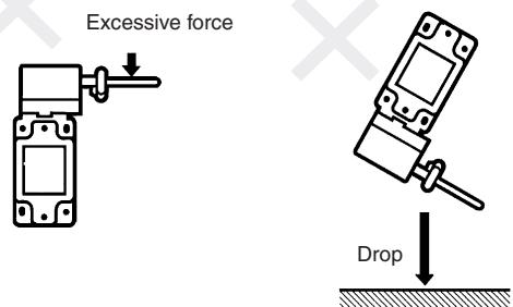
Secure the Operation Key with a one-way screw, or an equivalent, so that the Operation Key cannot be easily removed.
Securing the Door
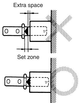
If the Operation Key on the closed door is pulled outside the set zone by a force caused by vibration, the door's weight, or the door cushion rubber, the switch contact may be opened (causing the machinery to stop) or the D4BS may be damaged. Secure the door with hooks so that it will remain within the set zone.
Mounting
Do not use the Switch as a stopper. Be sure to install a stopper as shown in the following illustration when mounting the Switch. The range of space “a” must be determined according to the available set zone of the Operation Key.

Refer to Dimensions for the mounting dimension of the Operation Key and mount the Operation Key correctly. The Operation Key will soon become damaged or worn out if it is not mounted correctly.
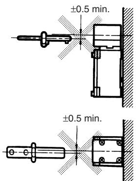
Make sure that the Operation Key can be inserted properly with a tolerance of ±0.5 mm in the upward, downward, left, or right direction, otherwise the D4BS may soon become damaged.
Other
Make sure that the D4BS is located outside the safety door and that no metal dust, oil, or chemical will be sprayed onto the D4BS. Otherwise, the D4BS may soon fail to operate due to the penetration of metal dust, oil, or chemical.
Tightening Torque
Be sure to tighten each screw of the D4BS properly, otherwise the D4BS may malfunction.
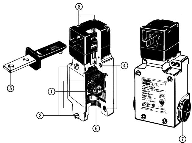
| No. | Type | Torque |
| 1 | M3.5 terminal screw (including ground terminal screw) | 0.59 to 0.78 N·m |
| 2 | Cover mounting screw(see note 1) | 1.18 to 1.37 N·m |
| 3 | Head mounting screw | 0.78 to 0.98 N·m |
| 4 | M5 body mounting screw(see note 2) | 4.90 to 5.88 N·m |
| 5 | Operation Key mounting screw | 2.35 to 2.75 N·m |
| 6 | Connector | 1.77 to 2.16 N·m |
| 7 | Cap screw | 1.27 to 1.67 N·m |
Note: 1. Apply a torque of 0.78 o 0.88 N·m if the D4BS is a three-conduit model.
2. Apply a torque of 4.90 to 5.88 N·m in the case of an Allenhead bolt. If it is a pan head screw, apply a torque of 2.35 to 2.75 N·m.
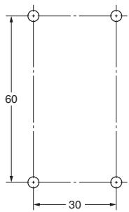
Mounting Dimensions (M5)
Standard Model
Three-conduit Model
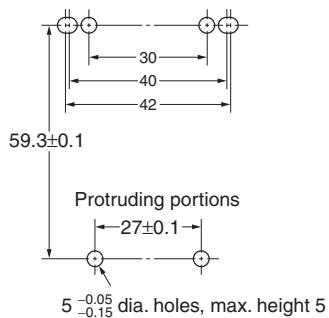
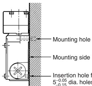
The D4BS can be mounted more securely by adding two protruding portions, each of which is 5 mm maximum in height and
5^-0.05/_-0.15 mm in diameter as shown below.
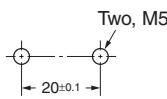
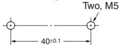
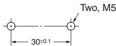
Operating Key Mounting Dimensions
Horizontal Mounting
Vertical Mounting
Adjustable Mounting (Horizontal)
Changes in Head Mounting Direction
By removing the screws on the four corners of the head, the head can be reset in any of four directions. The head direction can be changed with or without the Operation Key inserted in the head. Make sure that no foreign materials penetrate through the head and that the head is tightened securely within the proper torque range.
Wiring
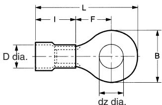
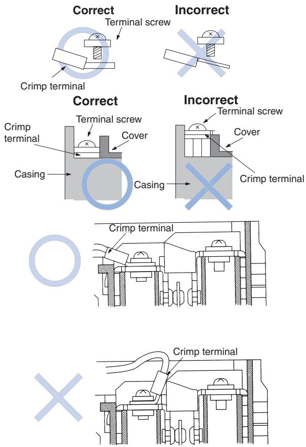
Do not connect the lead wires directly to the terminals. Connect the lead wires through insulation tubes and M3.5 crimp terminals. Tighten each terminal screw within the proper torque range.
The proper lead wire is AWG20 to AWG14 (0.5 to 2.5 mm ^4 ) in size.
| dz dia.: | 3.7 |
| D dia.: | 4.5 |
| B: | 7.0 |
| L: | 20.2 |
| F: | 7.7 |
| I: | 9.0 (mm) |
Make sure that all crimp terminals are correctly connected and located within the casing or cover as shown below.
Connector
Tighten the connector to a suitable torque. Excessive tightening torque may damage the casing.
When using a 1/2-14NPT conduit, apply sealing tape between connector and conduit opening so that the enclosure will confirm to IP67. If using a Pg13.5 conduit, use an ABS-08 Pg13.5 connector or an ABS-12 Pg13.5 connector (manufactured by Nippon Flex).
Use a connector (SC Series, sold separately) suitable for the outer diameter of the cable.
When wiring a 3-conduit model, securely tighten the cap screw provided for unused conduit openings.
Maintenance and Repairs
The user must not maintain or repair equipment incorporating any D4BS model. Contact the manufacturer of the equipment for any maintenance or repairs required.
ALL DIMENSIONS SHOWN ARE IN MILLIMETERS.
To convert millimeters into inches, multiply by 0.03937. To convert grams into ounces, multiply by 0.03527.
Cat. No. C094-E2-04A-X
In the interest of product improvement, specifications are subject to change without notice.
- Safety-door Switch
- D4BS
- Model Number Structure
- Switch
- Conduit
- Built-in Switch
- Head Mounting Direction
- Operation Key
- Operation Key Type
- Ordering Information
- Specifications
- Standards and EC Directives
- Approved Standard Ratings
- UL/CSA (UL508, CSA C22.2 No. 14)
- Set Zone Mark
- Head
- Seal Ring (NBR)
- Oil Seal (NBR)
- Seal Packing (NBR)
- Conduit Opening
- Built-in Switch
- Ground Terminal Screw
- Dimensions
- Switches
- Operation Keys
- With Operation Key Inserted
- Precautions
- Correct Use
- Operating Environment
- Securing the Door
- Mounting
- Other
- Tightening Torque
- Mounting Dimensions (M5)
- Operating Key Mounting Dimensions
- Changes in Head Mounting Direction
- Wiring
- Connector
- Maintenance and Repairs
Marque : OMRON
Modèle : D4BS
Catégorie : Capteurs de proximité