HC500 - Système de contrôle d'accès CHAMBERLAIN - Notice d'utilisation et mode d'emploi gratuit
Retrouvez gratuitement la notice de l'appareil HC500 CHAMBERLAIN au format PDF.
| Type d'appareil | Portail automatique |
| Fonction principale | Ouverture et fermeture automatique de portail |
| Sécurité | Respect des consignes de sécurité strictes |
| Installation | Conforme aux normes électriques et du bâtiment |
| Alimentation électrique | Connexion au réseau électrique principal |
| Commande | Activation uniquement en pleine ouverture |
| Maintenance | Manuel disponible pour entretien et réparation |
| Déconnexion électrique | Recommandée avant toute réparation |
| Accessoires | Ne pas laisser les enfants accéder aux boutons ou télécommandes |
| Utilisation | Ne pas forcer ou réparer soi-même, faire appel à un professionnel |
| Équipement de sécurité | Éviter les objets derrière le portail en mouvement |
| Consignes d'usage | Ne pas s'appuyer ou grimper sur le portail |
| Garantie | Non précisé |
| Accessoires fournis | Non précisé |
| Instructions | Manuel multilingue inclus |
| Précautions | Ne pas permettre aux enfants de jouer avec le portail |
| Réparations | Doivent être effectuées par un professionnel |
| Déverrouillage | Déverrouillage manuel possible en cas de panne |
FOIRE AUX QUESTIONS - HC500 CHAMBERLAIN
Questions des utilisateurs sur HC500 CHAMBERLAIN
0 question sur cet appareil. Repondez a celles que vous connaissez ou posez la votre.
Poser une nouvelle question sur cet appareil
Téléchargez la notice de votre Système de contrôle d'accès au format PDF gratuitement ! Retrouvez votre notice HC500 - CHAMBERLAIN et reprennez votre appareil électronique en main. Sur cette page sont publiés tous les documents nécessaires à l'utilisation de votre appareil HC500 de la marque CHAMBERLAIN.
MODE D'EMPLOI HC500 CHAMBERLAIN
START BY READING THESE IMPORTANT SAFETY RULES

These safety alert symbols mean Caution - a personal safety or property damage instruction. Read these instructions carefully.

This gate opener is designed and tested to offer reasonable safe service provided it is installed and operated in strict accordance with the following safety rules.
Failure to comply with the following instructions may result in serious personal injury or property damage.

Keep gate balanced. Sticking or binding gates must be repaired. Do not attempt to repair the gates yourself. Call for service.

Handle tools and hardware carefully and do not wear rings, watches or loose clothing while installing or servicing a gate opener.

Installation and wiring must be in compliance with your local building and electrical codes. Connect the power cord only to properly earthed mains.

Ensure that persons who install, maintain or operate the gate opener follow these instructions.

Keep this manual where it can be readily referenced during maintenance.

Disengage all existing gate locks to avoid damage to gate opener.

CAUTION: Activate opener only when the gate is in full view, free of obstructions and opener is properly adjusted. Do not allow children to play near the gate.

Disconnect electric power to the gate opener before making repairs.

Keep additional accessories out of the reach of children. Do not allow children to operate push button(s) or remote control(s). Serious personal injury from a closing gate may result from misuse of the opener.
Contents:
Safety Rules: Page 1
Contents of the carton: Page 2, Illustration 1
Product description: Page 2, Illustration 2
Technical data: Page 2
Installation:Pages 2-3,Illustrations 3-6
Operation: Page 3
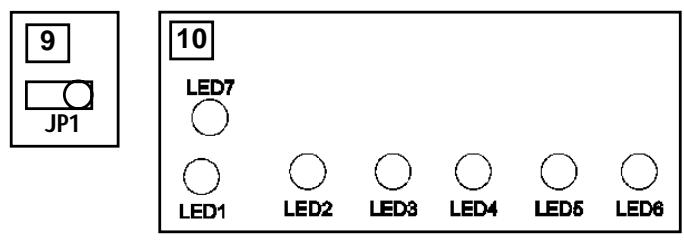
Instruction Manual Electronic Control: Page 4
Technical Features: Page 4
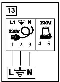
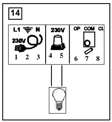
Electrical Installation: Page 4, Illustration 7
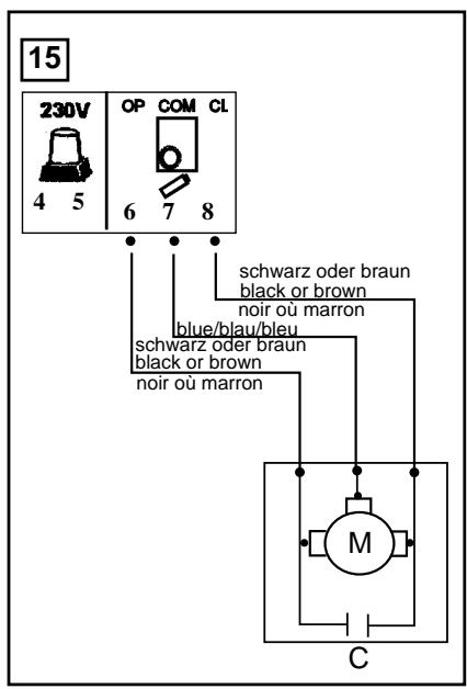
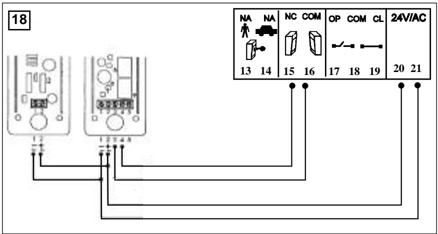
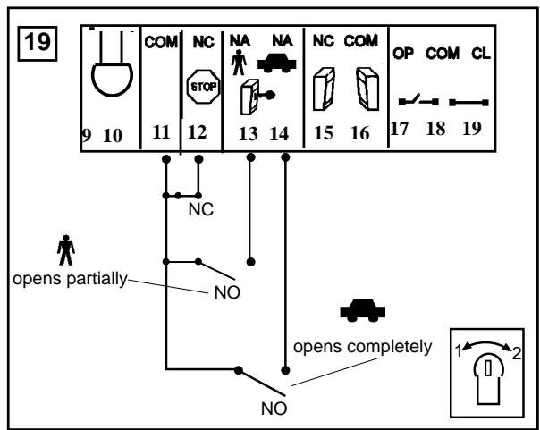
Summary of Motor Control Connections: Pages 5-6, Illustrations 8 -12
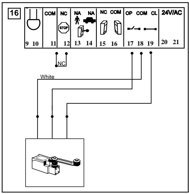
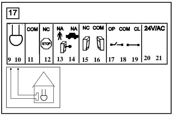
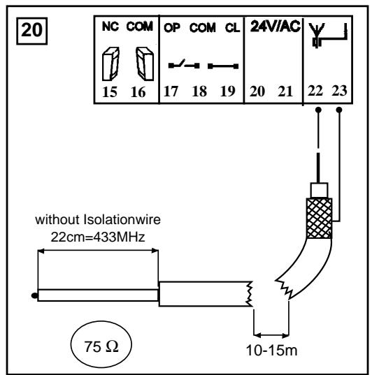
Installation of Accessories: Page 6, Illustrations | 13 | - | 20
Setting of Motor Control System: Page 7
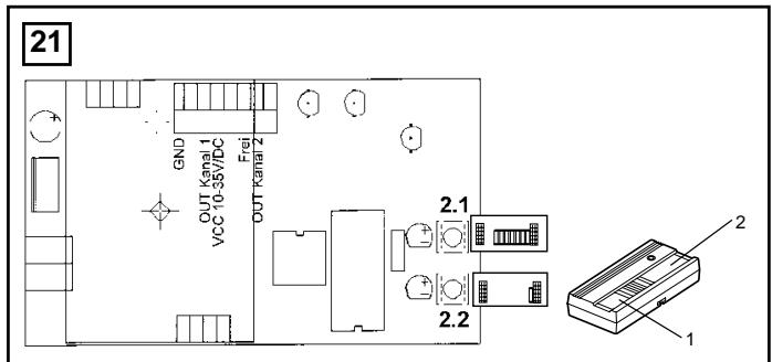
Setting of Remote Control: Page 7, Illustration 21
Warranty: Page 8
Accessories: Page 11, Illustration 22
BEGINNEN SIE MIT LESEN DIESER WICHTIGEN SICHERHEITSREGELN

Solche Warnzeichen bedeuten "Vorsicht!", eine Aufforderung zur Beachtung, da ihre Mißachtung Personen- bzw. Sachschäden verursachen kann.itte lessen Sie diese Warnungen sorgfällig.

Dieser Toröffner ist so konstruiert und geprüft, daß er bei Installation und Benutzung unter genauer Befolgung der anschließenden itsregeln angemessene Sicherheit bietet.
Die Nichtbeachtung der folgenden Sicherheitsregeln kann ernsthafte Personen- oder Sachschäden verursachen.

Esistwichtig,dasTorimmergutgangbarzuhalten.Toredie steckenbleibenoderverklemmen, sind unverzuglich zu reparieren.Versuchen Sienichtdas Tor selbst zu reparieren.BestellenSiedafur einenFachmann.

Beim Umgang mit Werkzeugen und Kleinteilen Vorsicht walten{lassen und weder Ringe, Uhren noch lose Kleidungsstücke tragen, wenn Sie Installations- oder Reparaturarbeiten an einem Tor vornehmen.
Elektrische Leitungen sind entsprechend den lokalen Bau- und Elektroinstallationsvorschriften zu verlegen. Das elektrische Kabelarfur an ein ordnungsgemäß geerdetes Netz angeschlossen werden.

Stellen Sie sicher, daß Personen, die den Antrieb montieren, warten oder bedienen diesen Anleitungen folgen.

Bewahren Sie die Anleitung an einem Ort auf, an dem schnell auf sie zurückgegriffen werden kann.

Enffernen Sieitte alle am Tor angebrachten Schlosserum Schaden am Tor zu vermeiden.

VORSICHT! Betätigten Sie den Offner nur, wenn Sie das Tor voll im Blickfeld haben, sich Dort keine behindernden Gegenstände befinden und der Offner richtig eingestellt ist. Kinder sollen nicht in Tornahe bei Betätigung des Offners spielen.

Unterbrechen Sie den Storm zum Torantrieb bevor Sie Reparaturen machen.

Entfernen Sie zusätzliches Zubehör aus der Nähe von Kindern. Erlauben Sie Kindern nicht Drucktaster und Fernbedienungen zu bedieten. Schwere Verletzungen können durch ein sich schließendes Tor verursacht werden.
Inhalt:
Sicherheitsregeln:Seite 1
Inhalt des Kartons: Seite 1, Abbildung 1
Produktbeschreibung: Seite 2, Abbildung 2
Technische Daten:Seite 2
Installation:Seite 2-3,Abbildungen3-6
Bedienung:Seite 3
Montageanleitung Steuerung:Seite 4
Technische Eigenschaften:Seite 4
Elektrische Installation:Seite 4,Abbildung
Anschlußübersicht:
Seite 5-6, Abbildungen 8 -12
Montage von Zubehör: Seite 6, Abbildungen [13] - | 20
Grundeinstellung: Page 7
Inbetriebnahme der Fernbedienung:Seite 7
Abbildung 21
Garantie:Seite 8
Zubehör:Seite 11,Abbildung 22
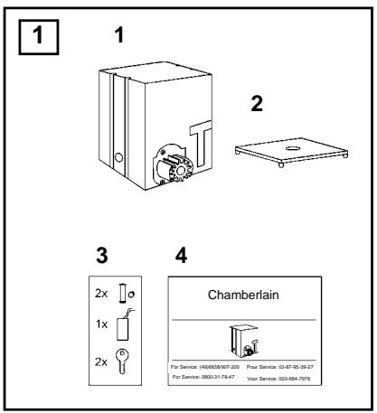
CONTENTS OF THE CARTON
(1) Sliding gate actuator unit
(2) Base Plate
(3) Installation accessories pack Hinge pins with circlips (2) Emergency opening handle (1) Capacitor (1)
(4) Instruction manual
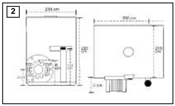
PRODUCT DESCRIPTION 2
For HC500, the maximum gate width may not exceed 6 m. The maximum weight may not exceed 600 kg.
For design reasons, all sliding gate actuator units, operating with a linear movement, must follow the given installation dimensions.
Technical data
| Power supply | 230V/50 Hz |
| Current Rating | 1,5 A |
| Power | 350 Watt |
| Capacitor | 10 mF |
| Cycles/Hr.-max | 20 |
| Speed | 12m/min. |
| Max. width of gate | 6 m |
| Max. weight of gate | 600 kg |
| Motor thermal overload switch | 140°C |
| IP Rating Motor | IP 54 |
| Rated weight | 10 kg |
| Dimensions | refer to Illustration 2 |
INSTALLATION 3 -6
PREPARATIONS
Before installation, please check contents of packaging. Please refer to Illustration 1.
Ensure your gate equipment functions correctly. The gate must move smoothly without jerking and must not stick at any point. Take into account the fact that the ground level may raise by several centimetres in the winter.
To avoid undesirable jerking movement, the gate should be stable and should have as little play as possible. The easier the gate movement, the finer the torque adjustment.
PROCEDURE:
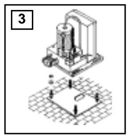
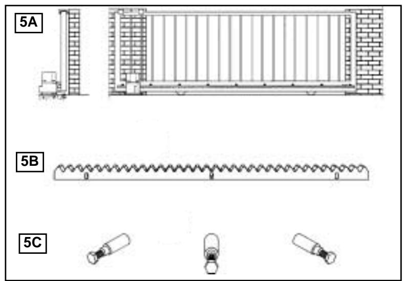
ASSEMBLY OVERVIEW
The assembly process is shown in Illustration 3 - 5. The drive must be mounted behind the wall, so that no part of it is visible in the gate opening (Illustracion 5A). The motor is mounted on the embedded base plate (Illustration 4). The toothed rack shown in Illustration 5B should be mounted on the gate with the aid of the mounting bolts (Illustration 5C).
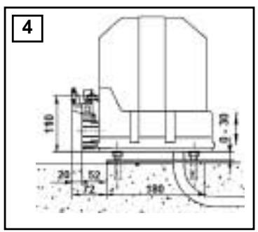
ASSEMBLY DIMENSIONS
Determine the appropriate height for mounting the toothed rack on the gate, and determine the assembly dimensions for the motor unit and base plate with reference to Illustration 4. If the gate design is unsuitable for direct mounting of the toothed rack, a mounting support (angular steel section, moulded tube, etc.) must be mounted first.
INHALT DES KARTONS 1
(1) Schiebetorantrieb
(2) Bodenplatte
(3) Montagezubehrbeutel Befestigungsbolzen mit Sicherheitsringen (2) Notentriebelung (1) Kondensator (1)
(4) Montageanleitung
PRODUKT BESCHREIBUNG 2
Beim HC500 davon die Torbreite 6 m nicht übersteigen. Das maximale Gewicht darf 600 kg nicht übersteigen. Bauartbedingt müssen bei allen Schiebertorantrieben, die mit linearer Bewegung arbeiten, bestimmte Einbaumße eingehalten werden.
Technische Daten
| Netzanschluß | 230V/50 Hz |
| Stromaufnahme | 1,5 A |
| Leistungsaufnahme | 350 Watt |
| Kondensator | 10 mF |
| Öffnungszyksen | 20 |
| Torblattgeschwindigkeit | 12m/min. |
| Max. Torbreite | 6 m |
| Max. Torgewicht | 600 kg |
| Motorthermoschutz | 140° C |
| Schutzgrad Motor | IP 54 |
| Nettogewicht | 10 kg |
| Abmessungen | siehe Abb. 2 |
INSTALLATION 3 - 6
VORBEREITUNGEN
Überprüfen Sieittevor der Montage den Inhalt der Verkaufsverpackung auf Vollständigkeit. Siehe Abbildung 1. Stellen Sie die einwandfrei Arbeitswise Ihrer Torvorrichtung safer. Das Tor muß gleichmäßig und stofffrei laufen, es dar an keiner Stelle hängenbleiben. Denken Sie daran, daß sich der Boden im Winter um eine Zentimeter haben kann. Um störende Pendelbewegungen zu vermeiden sollen das Tor stabil und möglichst spielfrei sein. Je leichtgänger der Flügel,esto feinfühliger ist die Kraft einzustellen.
VORGEHENSWEISE:
MONTAGEÜBERSICHT
Eine Montageübersicht zeigen die Abbildungen 3 bis 5. Der Antrieb muß hinter der Mauer so angebracht werden, daß kein Teil in die Toröffnung hereininragt (Abb. 5a). Auf die eingelassene Grundplatte (Abb 4) wird der Motor montiert. Die in Abb. 5b gezeigte Zahnstange ist mit Hilfe der Befestigungsbolzen (Abb. 5c) am Tor zu befestigen.
MONTAGEMABE
Stellen Sie fest, in welcher Höhe am Tor die Zahnstange am geeignetsten anzubringen ist und ermitteln Sie anhand der Abbildung 4 die Montagemaße für Motoreinheit und Grundplatte. Wenn die Torkonstruktion zum Befestigen der Zahnstange nicht geeignet ist, muß ein Befestigungsprofil (Winkeleisen, Formrohr etc.) montiert werden.
ASSEMBLY OF DRIVE BASE PLATE
The drive base plate can be embedded in concrete, mounted with dowels or welded on to the underlying surface.
ASSEMBLY OF MOTOR AND GEAR UNIT
The drive is now placed on the threaded bolts of the base plate as shown in Illustration 3. The height should be adjusted so that the distance between the cogwheel and the toothed rack is about 1 - 2cm . The long holes can be used to position the drive in relation to the toothed rack so as to comply with the assembly dimensions of Illustration 4.
ASSEMBLY OF TOOTHED RACK
After the motor and gear unit has been mounted, the rack rail can be mounted on the gate. Suitable mounting screws should be used to mount the rack to the gate. The simplest and fastest method of mounting the rack rail is to use self-tapping and self-cutting steel screws (e.g. 6.3 x 25 PIAS screws from Würth or the like).
If such screws are not available and if steel gates are used, an M6 thread must be cut. Please take care to ensure that the mounting screws are placed in the middle of the long holes on the mounting holder, so that the position of the rack rail can be corrected later.
NB: The simplest way of mounting the rack rail is to place it on the drive cogwheel of the motor, unlock the motor, and push the gate gradually open with the rack rail on it, screwing in the screws one by one in the process. This will ensure optimum meshing of the rack rail with the cogwheel.
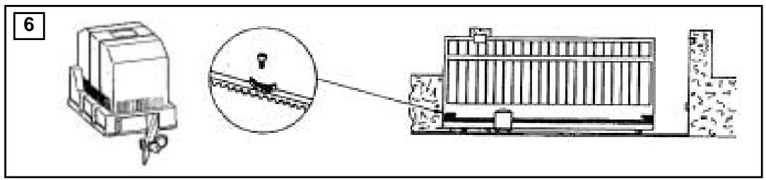
UNCOUPLING OF DRIVE
A lockable uncoupling device is provided so that the gate can be opened by hand in case of a power failure. The uncoupling process is shown in Illustration 6. The uncoupling lever can be unlocked and opened with the key, which releases the connection between the cogwheel and the worm gear. If the lever is returned to its original position, the drive is automatically coupled again.
ASSEMBLY OF LIMIT-SWITCH BRACKETS
The drive should be uncoupled before this part of the assembly work is carried out. Slide the gate into the closed position. Mount the limit switch bracket such that the roller of the switch is situated approximately int the middle of the bracket. Repeat this process for the open position. The bracket should be mounted with M6 screws with shims and washers. It is recommended that a 4.8mm hole be drilled in the toothed rack and an M6 thread cut in it. After final adjustments, the bracket can be fixed in place with the screw.
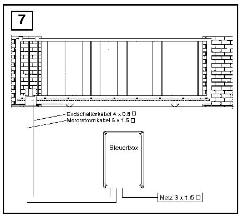
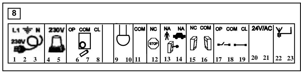
ELECTRICAL CONNECTIONS
Details of the electrical connections may be found in the instructions for the logic control box.
OPERATION
The sliding gate actuator can be operated by the remote control. After disengaging the drive coupling using the key provided, the gate can be operated manually.
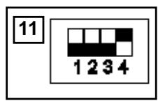
Various operation modes can be preset by changing the dip switches on the electronic control.
MONTAGE DER ANTRIEBSGRUNDPLATTE
Die Antriebsgrundplatte kann einbetoniert, angedüelt oder auch angeschweit werden.
MONTAGE DER MOTOR- UND GETRIEBEINHEIT
Der Antrieb wird dann gemäß Abb. 3 auf die Gewindebolzenden Grundplatte gesetzt. Die Höhe ist so einzustellen, daß zwischen Zahnrad und Zahnstange ca. 1 - 2 cm Abstand ist. Mittels der Langlocher kann der Antrieb so eingestellt werden, daß seine Lage zur Zahnstange den Montagemaßen aus Abb. 4 entspricht.
MONTAGE DER ZAHNSTANGE
Nachdem die Motor- und Getriebeeinheit montiert ist, kann die Zahnschiene am Tor befestigt werden. Dazu sind an der Zahnschiene angespritzte Halterungen mit Langlochemn für die Befestigungsschrauben vorhanden. Am schnellsten und einfachsten erfolgt die Montage der Zahnschiene mit selbstbohrenden und selbstschneidenden Stahlschrauben (z.B. PIAS-Schrauben 6,3 x 25 von der Fa. Würth oder ähnliches). Stehen solche Schrauben nicht zur Verfügung, muß bei Stahltoren ein M6-Gewinde geschritten werden.itte beachten Sie, daß die Befestigungsschrauben in der Mitte der Langlocher am Befestigungshalter angebracht werden, damit die Position der Zahnschiene später noch korrigiert werden kann.
Hinweis: Am einfachsten laßt sich die Zahnschiene montieren, wenn man die Zahnschiene bei der Montage auf dem Antriebszahnrad des Motors auflegt, den Motor entriegelt und durch Weiterschieben des Tores mit der aufgelegten Zahnschiene diese Stück für Stück festschraubt. Dadurch ist immer garantiert, daß die Zahnschiene mit dem Zahnrad optimal im Eingriff ist.
ENTKUPPLUNG DES ANTRIEBES
Um das Tor bei Stromausfall von Hand betätigten zu konnen, ist eine versperrbare Entkupplungsvorrichtung eingebaut. Die Entkupplung ist in Abb. 6 dargestellt. Der Entkupplungshebel kann mit Hilfe das Schlüssels Herausgehaklappt werden. Dadurch lost eine Klauenkapplung die Verbindung zwischen Zahnrad und dem selbsthemmenden Schneckengetriebe. Wird der Hebel zurückgeklappt, erfolgt die Wiedereinkupplung automatisch.
MONTAGE DER ENDSCHALTER
Vor der Montage ist der Antrieb zu entkuppeln. Montieren Sie dann wie in Abb. 5 gezeigt die beiden Endschalterbürger so, daß die Rolle des Endschalters etwa in der Mitte des Bügels stehen. Zu dieser Zweck schiben Sie das Tor in die jeweilige gewünschte Endposition. Die Bürger sind durch M6-Schrauben mit Beilagscheiben und Federring zu befestigen. Bohren Sie dazu in die Zahnstange ein Loch mit 4,8 mm Δ und schneider Sie ein Gewinde M6. Die Bürger können dann nach der endgültigen Einstellung durch die M6-Schrauben gesichert werden.
ELEKTRISCHER ANSCHLUB
Naheres zum elektrischen Anschluß kann der Anleitung zur Steuerelektronik werden.
BEDIENUNG
Der Schiebetoröffner kann durch Taster, Schlüsselschalter oder Schlüssellose Schalter oder per Fernbedienungsseteingeschaltet werden: Nach Entkuppelung des Antriebs mit dem zugehörigen Schlüssel kann das Tor von Hand geöffnet werden. Der Funktionsblauf nach Betätigung des Befehlgebers (Fernbedienung, Taster etc) hängt von der Einstellung der vier Dippschalter der Steuerelektronik ab.