
7255 - Imprimante multifonction KONICA MINOLTA - Notice d'utilisation et mode d'emploi gratuit
Retrouvez gratuitement la notice de l'appareil 7255 KONICA MINOLTA au format PDF.
| Type de produit | Imprimante multifonction (copieur, scanner, option imprimante/réseau) |
| Marque | KONICA MINOLTA |
| Modèle | 7255 |
| Vitesse de copie | 55 copies/minute (A4) |
| Résolution de copie | 600 x 600 ppp (par défaut) |
| Formats de papier supportés | A3, B4, A4, A4R, B5, A5, formats personnalisés (via bac multifonction) |
| Capacité papier standard | 3 600 feuilles (2 bacs de 500, 1 bac de 1 500, 1 bac de 1 000, bac multifonction de 100) |
| Capacité papier maximale | 7 600 feuilles (avec bac grande capacité LT-402/LT-412 en option) |
| Alimentation électrique | 230V ~ 50/60 Hz, >10A |
| Dimensions (L x P x H) approximatives | 650 x 700 x 900 mm (corps principal) |
| Poids approximatif | 110 kg (corps principal, sans options) |
| Fonctions principales | Copie recto-verso automatique, tri, agrafage (avec finisseur), perforation (option), pliage (option), impression de couverture, mode livret, duplication, combinaison 2/4/8 pages par feuille, programmation de travaux, fonctions réseau (option) |
| Sécurité | Étiquettes d'avertissement, protection contre les hautes tensions, arrêt automatique, mode économie d'énergie, verrouillage du panneau |
| Entretien et nettoyage | Nettoyage régulier de la vitre d'exposition, du guide RADF, du bac de déchets, ajout de toner et d'agrafes, vidage des déchets de perforation |
| Pièces détachées et réparabilité | Cartouche de toner, agrafes, bac de déchets, kit d'entretien (unité de fixation, tambour). Pour toute réparation ou pièce, contacter le service après-vente agréé |
| Informations générales | Écran tactile LCD, panneau de contrôle inclinable, fonction Auto Low Power et Auto Shut-Off pour économies d'énergie, compatible avec les programmes ENERGY STAR®. Notice d'utilisation de 436 pages disponible en téléchargement. |
FOIRE AUX QUESTIONS - 7255 KONICA MINOLTA
Questions des utilisateurs sur 7255 KONICA MINOLTA
0 question sur cet appareil. Repondez a celles que vous connaissez ou posez la votre.
Poser une nouvelle question sur cet appareil
Téléchargez la notice de votre Imprimante multifonction au format PDF gratuitement ! Retrouvez votre notice 7255 - KONICA MINOLTA et reprennez votre appareil électronique en main. Sur cette page sont publiés tous les documents nécessaires à l'utilisation de votre appareil 7255 de la marque KONICA MINOLTA.
MODE D'EMPLOI 7255 KONICA MINOLTA
Konica 7255 7272
#
1 Basic
2 Advanced
Thank you very much for your purchase of the Konica 7255/7272.
This Manual deals with making copies, correct handling of the machine, and precautions for safety. Please read before copying.
In order to maintain a satisfactory copying performance, please keep this Manual readily available for reference in the side pocket of the machine.

ENERGY STAR® Program
The ENERGY STAR Program has been established to encourage the widespread and voluntary use of energy-efficient technologies that reduce energy consumption and prevent pollution. As an ENERGY STAR Partner, we have determined that this product meets the ENERGY STAR guidelines for energy efficiency grounding it on the following features.
Auto Low Power
This function conserves energy by lowering the set temperature of the fixing unit. In the standard setting, Auto Low Power operates automatically when 1 minute have elapsed after completion of the last copy, with the copier remaining in the ready to copy state during that time.
The time period for the Auto Low Power function can be set for 1 minute, 5 minutes, 10 minutes, 15 minutes, 30 minutes, 60 minutes, 90 minutes, 120 minutes, or 240 minutes. See p. 2-21 for details.
Automatic Shut-Off
This function achieves further energy conservation by partially turning OFF the power supply, thereby reducing energy consumption to 20W or less. In the standard setting, Automatic Shut-Off follows Auto Low Power, operating automatically when 15 minutes have elapsed after completion of the last copy, with the copier remaining in the ready to copy state during that time.
The time period for the Automatic Shut-Off function can be set for 1 minute, 5 minutes, 10 minutes, 15 minutes, 30 minutes, 60 minutes, 90 minutes, 120 minutes or 240 minutes. See p. 2-21 for details.
Automatic Duplex Copying
To reduce paper consumption, use this function to make double-sided (duplex) copies, automatically.
We recommend that you utilize the Auto Low Power function, the Automatic Shut-Off function, and the Automatic Duplex Copying function.
Copyright © 2000 GoAhead Software, Inc. All rights reserved.
Contents
Features of the Konica 7255/7272
Basic
Section 1: Safety Information
Caution Labels and Indicators 1-2
Requirements for Safe Use 1-7
Power Source 1-7
Environment. 1-8
Precautions for Routine Handling 1-12
Section 2: Machine Information
Machine Configuration 2-2
External Machine Items 2-2
Internal Machine Items 2-5
Standard/Optional Equipment 2-6
FS-110/FS-210 Finisher (+PK-110/120/120 Type-A Punching Kit) ... 2-8
FS-111 Finisher 2-10
PI-110 Cover Sheet Feeder 2-12
PZ-108/PZ-109 Punching / Z-Folding Unit 2-13
SF-101 Shift Tray 2-14
Control Panel Layout 2-15
Basic Screen 2-16
Turning On the Main Power Switch and Power Switch 2-18
To Turn On the Power 2-18
To Turn Off the Power 2-20
Reducing the Power in Standby Mode (Auto Low Power) 2-21
Shutting Off Automatically (Auto Shut-Off) 2-21
Shutting Off / Reducing the Power Manually 2-22
Entering an EKC Password (EKC) 2-23
Loading Paper 2-24
Loading Paper in Tray 1 and 2 2-24
Loading Paper in Tray 3 and 4 2-26
Loading Paper in LCT (LT-402/LT-412) 2-28
Loading Paper in Multi-Sheet Bypass Tray 2-30
Loading Tabbed Sheets in Tray 3 or 4 2-31
Loading Tabbed Sheets in LCT (LT-402/LT-412) 2-32
Loading Tabbed Sheets in Multi-Sheet Bypass Tray 2-33
Changing Paper Size of Tray 3 and 4 2-34
Section 3: Copying Operations
Positioning Originals 3-2
Positioning Originals in RADF 3-2
Positioning Original on Platen Glass 3-5
Setting Print Quantity 3-6
To Set Print Quantity 3-6
To Change Print Quantity 3-6
Setting Job During Warm-up 3-7
To Stop Scanning/Printing 3-9
Selecting Paper Size 3-10
To Select Paper Size Automatically (APS) 3-10
To Specify Desired Paper Size (AMS) 3-12
Selecting Magnification Ratio (Lens Mode) 3-14
To Copy in 1.00 Magnification Mode 3-14
To Copy in Fixed Magnification Mode (RE) 3-15
To Copy in Zoom Mode 3-16
Selecting Density Level 3-18
To Select Copy Density 3-18
Density Shift. 3-20
Making Double-Sided Copy (1-2, 2-2) 3-21
Using RADF 3-21
Using Platen Glass 3-24
Making Single-Sided Copy from Double-Sided Originals (2-1) 3-27
Copying Using Special Paper (Multi-Sheet Bypass Tray) 3-29
Copying Using Memory 3-33
To Scan Originals into Memory (Store Mode) 3-33
To Set Next Copying Job (Reserve) 3-35
To Check/Control Jobs in Progress (Job Status Screen) 3-38
Output Mode for Machine without Finisher 3-41
Output Mode for Machine with Finisher 3-44
Output Mode for Machine with Shift Tray 3-50
Selecting Binding Mode 3-53
Recalling Previous Job Settings 3-54
Checking Feature Selections and Proof Copying 3-55
Interrupt Copying 3-59
Section 4: Job Memory & Help Mode
Storing Job Conditions (Job Memory: Job Store) 4-2
Recalling Stored Job Settings (Job Memory: Job Recall) 4-5
Displaying Screen for Operation Guide (Help Mode) 4-6
To Display Help Screen from Basic Screen 4-6
To Display Help Screen from Other Screens 4-8
Section 5: Troubleshooting
When "Call for Service" Message Is Displayed 5-2
Limited Use of the Copier in Trouble 5-3
Preventive Maintenance 5-4
To Check the PM Counter 5-4
Clearing Mishandled Paper 5-6
When "JAM" Appears on Folder Key (Or Arrow Key Flashes) 5-8
When "ADD PAPER" Appears on Folder Key (Or Arrow Key Flashes) ..5-10
When “Memory Full” Message Is Displayed (Memory Overflow) 5-11
Memory Overflow in Current Job 5-11
Memory Overflow in Reserve Job 5-12
When Power OFF/ON Screen Is Displayed 5-13
Troubleshooting Tips 5-14
Section 6: Machine Specifications
Main Body Specifications 6-2
Main Body. 6-2
RADF (DF-322) 6-3
Option Specifications 6-4
FS-110/210 In-Bin Stapler Finisher 6-4
FS-111 In-Bin Stapler Finisher 6-4
SF-101 Shift Tray. 6-4
PI-110 Cover Sheet Feeder 6-5
PK-110/120 Punching Kit 6-5
PK-120 Type-A Punching Kit 6-5
PZ-108 Punching / Z-Folding Unit 6-6
PZ-109 Punching / Z-Folding Unit 6-6
LT-402 Large Capacity Tray 6-7
LT-412 Large Capacity Tray 6-7
Expanded Memory Unit 6-7
Others 6-7
Advanced
Section 7: Advanced Information
Programmed Shut-Off (Weekly Timer) 7-2
Rotation 7-5
Vertical/Horizontal Zoom Mode 7-6
Making Folded Booklet (Fold / Stitch&Fold) 7-9
Punching File Holes in Copies (Punch) 7-12
Output Z-Folded Copies (Z-Fold) 7-16
Output Three-Folded Copies (Three-Fold) 7-18
Cover Sheet Feeding 7-20
Using Finisher Manually 7-24
Using Two Copiers in Tandem 7-27
To Stop Scanning/Printing 7-31
Troubleshooting 7-32
Section 8: Special Original
Specifying Original Direction 8-2
Selecting Original Binding Direction 8-4
Making Copy Quality Closer to Originals (Text/Photo Enhance) 8-6
Copying Mixed Size Originals (Mixed Original) 8-8
Copying Z-Folded Originals (Z-Folded Original) 8-10
Copying Non-Standard Size Originals (Original Form) 8-12
Section 9: Applications
To Display Application Selection Screen 9-2
Inserting Sheets and Covers (Sheet/Cover Insertion) 9-3
Locating Title Pages on the Right Side (Chapter) 9-7
Lay Out Several Pages onto One Sheet (Combination) 9-10
Making a Multiple Page Signature Booklet (Booklet) 9-13
Copying onto Transparent Films (OHP Interleave) 9-17
Inserting Images into Printed Sets (Image Insert) 9-19
Dividing an Image into Right and Left Pages (Dual Page) 9-22
Programming Different Settings for an Output Job (Program Job) 9-26
Erasing Outside of the Original (Non-Image Area Erase) 9-29
Reversing Colour in Black and White Image (Reverse Image) 9-31
Repeating Selected Image Area (Repeat: Vert./Horiz. Mode) 9-33
Repeating Automatically Or Selecting Repeating Times(Repeat: AUTO/
Repeat Mode) 9-36
Eliminating Black Copy Marks Along Borders (Frame/Fold Erasure) ....9-39
Section 9: Applications (continued)
Copying Image in the Centre of Copy Paper (AUTO Layout) 9-42
Printing Images Fully to the Edges (Full-Image Area) 9-44
Adjusting Position of Copy Image (Image Shift) 9-46
Reducing Images to Create Binding Margin (Reduce&Shift) 9-49
Printing Stamp, Page, Date/Time onto Copies (Stamp) 9-52
Printing Watermark onto Copies (Stamp) 9-58
Overlaying an Image onto Each Page Copied in the Job (Overlay) 9-61
Storing an Overlay Image in HDD / Overlaying Image Stored in HDD (Overlay Memory) 9-64
Section 10: Network Function
To Use Server Functions 10-2
Storing/Deleting Image Data in HDD/PC (Image Store/Delete) 10-4
To Store Image Data in HDD/PC 10-4
To Transmit Image Data from HDD to PC 10-8
To Delete Image Data from HDD/PC 10-13
Storing Image Data While Copying (Image Store&Output) 10-16
Recalling Image Data from HDD/PC (Image Recall) 10-19
Editing Image Data Using PC (Image Edit) 10-23
To Use Web Utilities 10-26
To Display Information on Machine 10-28
To Display Current Machine Status (Job Status) 10-29
Operating Image Data Stored in HDD (HDD Job Information) 10-31
Setting E-Mail Transmission Function (Environment Setup) 10-35
Setting E.K.C. Function (Environment Setup) 10-37
Setting Scan Transmission Function (Environment Setup) 10-47
Transmitting/Editing Machine Setting File (Environment Setup) 10-53
Section 11: Paper and Original Information
Paper Information 11-2
Paper Weight 11-2
Tray/Exit Tray Capacity 11-3
Paper Size 11-5
Special Paper in Multi-Sheet Bypass Tray 11-7
To Store Copy Paper 11-7
Original Information 11-8
Platen Glass Originals 11-8
RADF Originals 11-9
Section 12: Maintenance & Supplies
Adding Toner 12-2
Inserting a New Staple Cartridge into FS-110/210 Finisher 12-5
Inserting a New Staple Cartridge into FS-111 Finisher 12-8
Empty Waste Basket of PK-110/120/120 Type-A Punching Kit 12-12
Empty Waste Basket of PZ-108/109 Punching / Z-Folding Unit 12-14
Cleaning Image Scanning Section 12-16
Cleaning the Document Glass 12-16
Cleaning the Left Partition Glass 12-16
Cleaning the RADF Platen Guide Cover 12-17
Checking Copy Count 12-18
To Display the Counter List Screen 12-18
To Print the Counter List. 12-19
Copy Materials 12-20
Maintenance Kit 12-20
Section 13: Key Operator Mode
How to Access the Key Operator Mode 13-2
To Display the Key Operator Mode Screen 13-2
[1] System Initial Setting 13-4
[1] Date & Time Setting. 13-4
[2] Language Select Setting. 13-6
[3] IP Address Setting 13-7
[4] E-Mail Transmission Setting 13-8
[2] Copier Initial Setting 13-10
[3]User Setting Mode 13-12
[1]User Density Level 1 Setting. 13-12
[2]User Density Level 2 Setting. 13-13
[3] User Lens Mode Ratio Setting 13-14
[4] E.K.C. (Electronic Key Counter) Function Setting 13-15
How to Access the EKC Setting Mode 13-16
[1] E.K.C. Data Edit 13-17
[2] E.K.C. All Count Reset 13-20
[3] E.K.C. Function Setting 13-21
[5] Lock/Delete Job Memory 13-22
[6] Paper Type / Special Size Set 13-23
[7] Panel Contrast / Key Sound Adjustment 13-25
[8] Key Operator Data Setting 13-26
Section 13: Key Operator Modes (continued)
[9] Weekly Timer 13-27
How to Access the Weekly Timer Setting Mode 13-28
[1] Weekly Timer On/Off Setting 13-29
[2] Timer Setting 13-30
[3] Timer Action On/Off Setting 13-32
[4] Lunch Hour Off Setting 13-34
[5] Timer Interrupt Password Setting 13-35
[10] Control Panel Adjustment 13-36
[11] Tray Auto Select Setting 13-37
[12] Power Save Setting 13-38
[13] Memory Switch Setting 13-39
[14] Machine Management List Print 13-47
[15] Call Remote Centre 13-48
[16] Side 2 Lens Adjustment 13-49
[17] Finisher Adjustment 13-50
[18] HDD Management Setting 13-52
[19] Scan Transmission Setting 13-54
[20] Non-Image Area Erase Setting 13-56
[21] Background Adjustment 13-57
[22] Timing Adjustment 13-58
[23] Centring Adjustment 13-60
Index
- AE - Automatic Exposure
Automatically adjusts exposure to compensate for quality of the original.
- AMS - Automatic Magnification Selection
Automatically selects an appropriate magnification ratio when Paper Size is selected manually. Automatically selected when the AMS key is touched.
- APS - Automatic Paper Selection
Automatically selects copy paper size to match the original documents.
- ATS - Automatic Tray Switching
Automatically switches tray to allow copying to continue without interruption if the selected tray empties while copying is in progress.
- Auto Layout
The original image on the platen glass or in the document feeder is copied and centred on a sheet.
- Auto Low Power
Automatically lowers the power after a specified period of copier inactivity.
- Auto Reset
Automatically resets to auto mode defaults after a specified period of copier inactivity.
- Auto Shut-Off
Automatically shuts off the main power after a specified period of copier inactivity.
- Booklet
Creates A5 or A4 booklets from A4 size originals in 1-2 or 2-2 copy mode.
Chapter
Starts chapter pages on the right side (front pages) of the finished document. Only duplex mode (1-2) is compatible with this feature.
Combination
Copies a fixed number (2, 4, or 8) of pages onto one sheet of copy paper to create a draft copy of a multi-page report at the same time as saving paper.
- Copy Density
Manually selects up to 9 density levels.
- Copy Mode
Selects the desired simplex mode (1-1 or 2-1); or duplex mode (1-2 or 2-2).
Counter List
Displays on the screen and prints the following data: total counter of the machine, copier counter, print counter and the date when the counter started.
Density Shift
Shifts each of nine density levels in four density modes (Auto, Text, Photo, Increase Contrast) to three levels lighter or three levels darker.
- Dual Page
Copies both pages of an open book or book-size sheet separately onto two A4 sheets in 1-1 mode or separately onto each side of one A4 sheet in 1-2 mode. You can use the Dual Page mode with the Front or Front/Back cover mode. The cover page(s) will be scanned and copied normally before image division is performed on the other pages.
- Frame/Fold Erasure
Erases border and/or fold image area using Frame (1 - 300mm), Fold (1 - 99mm), or Frame & Fold.
- Full-Image Area
Makes copies printed completely to the edges of the paper to avoid image loss.
- Image Insert
Stores pages in memory from the platen glass, and inserts the pages into a document copied from the document feeder.
- Image Shift
Creates or removes a binding margin at the top, bottom, right and left edges (shift amount from 0 250mm , in 1mm increments); reduces image to prevent image loss (reduce & shift amount from 0 250mm , in 1mm increments).
- Interrupt Copying
Interrupts copying-in-progress to perform an urgent copy, using any of the copier features for the interrupt job.
Job Memory
Programs up to 30 jobs and recalls each job by job number or name, as needed. All compatible platen glass functions can be programmed into Job Memory directly after they are selected.
Job Status
Displays the Job Status Screen to view the current machine status, changes the operation order of reserve jobs, deletes the unused reserve job, or displays the previous job list.
- Lens Mode (RE, Zoom)
Selects fixed ratios, four reduction, four enlargement, and three user-set ratios. Zoom ratios can be selected from 25% 400% in 1% increments.
Machine Status Confirmation
Displays the current machine status on LCD for confirmation.
- Manual Shut-off
Shuts off the machine's power when pressing [POWER SAVER ON/OFF] on the control panel.
- Mixed Original
Copies mixed size originals from the document feeder in APS or AMS mode. APS automatically selects the paper size of each original. AMS mode allows you to select one paper size for all originals.
Network Function (option)
When the machine is connected to a PC over a network, it uses a web browser on the PC to manage the stored data, to check the machine or job information, and to perform the Key Operator settings concerning the network environment.
- Non-Image Area Erase
When copying from the platen glass when the document cover is open, copies only the image area and not the exposed area of glass, which would otherwise copy as black.
- Non STD Size for Multi-Sheet Bypass Tray
Enters the special paper size to be loaded on the Multi-sheet bypass tray using the touch screen keypad in order to avoid paper misfeed.
Non STD Size for Original
Identifies the special original size which the 7255/7272 cannot detect, in order to select the optimal paper size for copying or printing.
- OHP Interleave
When using transparency film, select either Blank or Copy Sheet Interleaving mode for each original.
- Output Mode for FS-110/210 Finisher with PI-110 Cover Sheet Feeder Installed:
Cover Sheet mode
Manual Finishing mode
For details, see Section 7: Advanced Information.
- Output Mode for Machine with FS-110/111/210 Finisher Installed: Non-Sort, Sort, Staple-Sort, and Group modes using the primary (main) tray Non-Sort Face Down exit, Non-Sort Face Up exit, Group Face Down exit, and Group Face Up exit modes using the secondary (sub) tray Fold, Stitch & Fold, and Three-Fold modes using the booklet tray (FS-210 only)
Selects an output tray and output mode on the Output Mode popup menu.
- Output Mode for Machine with SF-101 Shift Tray Installed:
Non-sort, Sort, and Group modes are available. Selects an output mode on the Output Mode popup menu.
- Output Mode for Machine with no Finisher Installed:
Non-sort, Rotation sort, Group, and Rotation group modes are available in combination with Face down or Face up exit. Selects an output mode on the Output Mode popup menu.
- Overlay
Inprints a scanned image onto the copy image.
- Overlay Memory
Stores the overlaying image in HDD and prints a stored image onto the copy image.
- Paper Capacity
Total 3,600 sheets, including two 500-sheet trays, a 1,500 sheet tray, a 1,000 sheet tray, and a 100-sheet Multi-sheet bypass tray.
Total 7,600 sheets, including 4,000-sheet optional large capacity tray.
- Platen Memory
Scans documents into memory from the platen glass and/or the document feeder and inserts the pages into another document copied from the document feeder. If an incompatible function is selected in this mode, the latter function will not be selected, and an Error message will be displayed.
Power Saver
Automatically turns off all but nominal power supply after a specified period of copier inactivity, for optimal efficiency. Power is returned after a brief warm up period by pressing [POWER SAVER ON/OFF] on the control panel.
- Program Job
Scans documents into memory while designating different copy conditions for each original, then prints all the documents collectively.
Proof Copy
To ensure correct output before running multiple copies, run a proof copy by pressing [PROOF COPY] on the control panel or touching PROOF COPY on the Check Screen.
- Punch Mode for FS-110/210 Finisher with PK-110/120/120 Type-A Punching Kit Installed:
Punches four holes in output copies.
PK-120 Type-A Punching kit punches four holes of the Swedish type.
- Punch/Z-Fold Mode for FS-110/111/210 Finisher with PZ-108 Punching/Z-Folding Unit Installed:
Punches four holes in output copies and Z-fold copied sheets.
- Punch/Z-Fold Mode for FS-110/111/210 Finisher with PZ-109 Punching/Z-Folding Unit Installed:
Punches two or four holes in output copies and Z-fold copied sheets.
Repeat
Selects the horizontal image area across the page, and repeats it down the page as many times as the repeat width setting (10 ~ 150mm) permits in manual or auto.
- Reserve
Scans in subsequent copy jobs while the 7255/7272 is busy printing or copying.
- Reverse Image
Reverses the image from black-on-white to white-on-black or vice versa.
- Rotation
Rotates the image before copying when the portrait/landscape orientation of the original is different from the orientation of the copy paper.
- Rotation Exit (Rotation Sort / Rotation Group)
When no Finisher is installed, Rotation exit alternately switches the horizontal and vertical orientation of each sorted set as it outputs to the exit tray. Be sure to load both A4 and A4R in separate trays (including the Multi-sheet bypass tray) before selecting this feature.
- Server Function (option)
Stores image data in the HDD for future printing (or transmits the data to a PC over a network for editing and printing).
- Sheet/Cover Insertion
Inserts up to 30 blank or copied sheets from any tray including the Multi-sheet bypass tray, or inserts blank or copied front and back covers from any tray including the Multi-sheet bypass tray.
- Stamp
Inprints a stamp, watermark, or scanned image onto the copy image.
Staple
Selects the stapling position and number of staples.
- STD Size (Special)
Detects the standard paper sizes which cannot normally be detected when loaded in a main body tray or Multi-sheet bypass tray.
- Tab Paper
Copies onto tabbed sheets from tabbed originals, allowing the image on the tab part of the original to be printed on the same part of the tabbed copy paper.
Tandem Mode for Two Copiers
Works in tandem to distribute a large copying job in half the time of non-tandem mode.
- Text/Photo Enhance
Enhances photo image in Photo mode, regular image in Auto mode, text image in Text mode, lighter image in Increase Contrast mode.
- 用户 Set Density (USERSET 1, USERSET 2)
Outputs up to 16 density samples on a total of 4 pages that display 4 samples per page, then programs the desired density under USERSET 1 and/or USERSET 2.
Weekly Timer
Can be set according to the needs of each work environment. Turns main body power Off/On daily or weekly, during lunch time, on holidays, and also enables the Timer Interrupt mode, which allows temporary use of the machine even when the machine is in the daily, weekly, or holiday Off mode.
Wide Size Paper
Copies onto paper slightly larger than the specified regular size.
- Z-Folded Original
This feature sets the RADF to accept Z-folded originals.
Basic
SECTION
1
Safety Information
Precautions for Installation and Use
Caution Labels and Indicators 1-2
Requirements for Safe Use 1-7
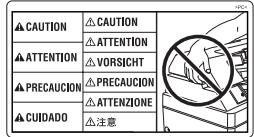
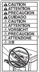
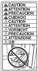
The caution labels and indicators are attached to the machine areas, as shown below, where you are advised to pay special attention to avoid any dangerous situations or serious injury.
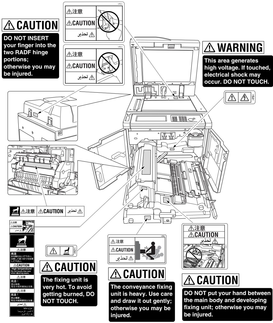
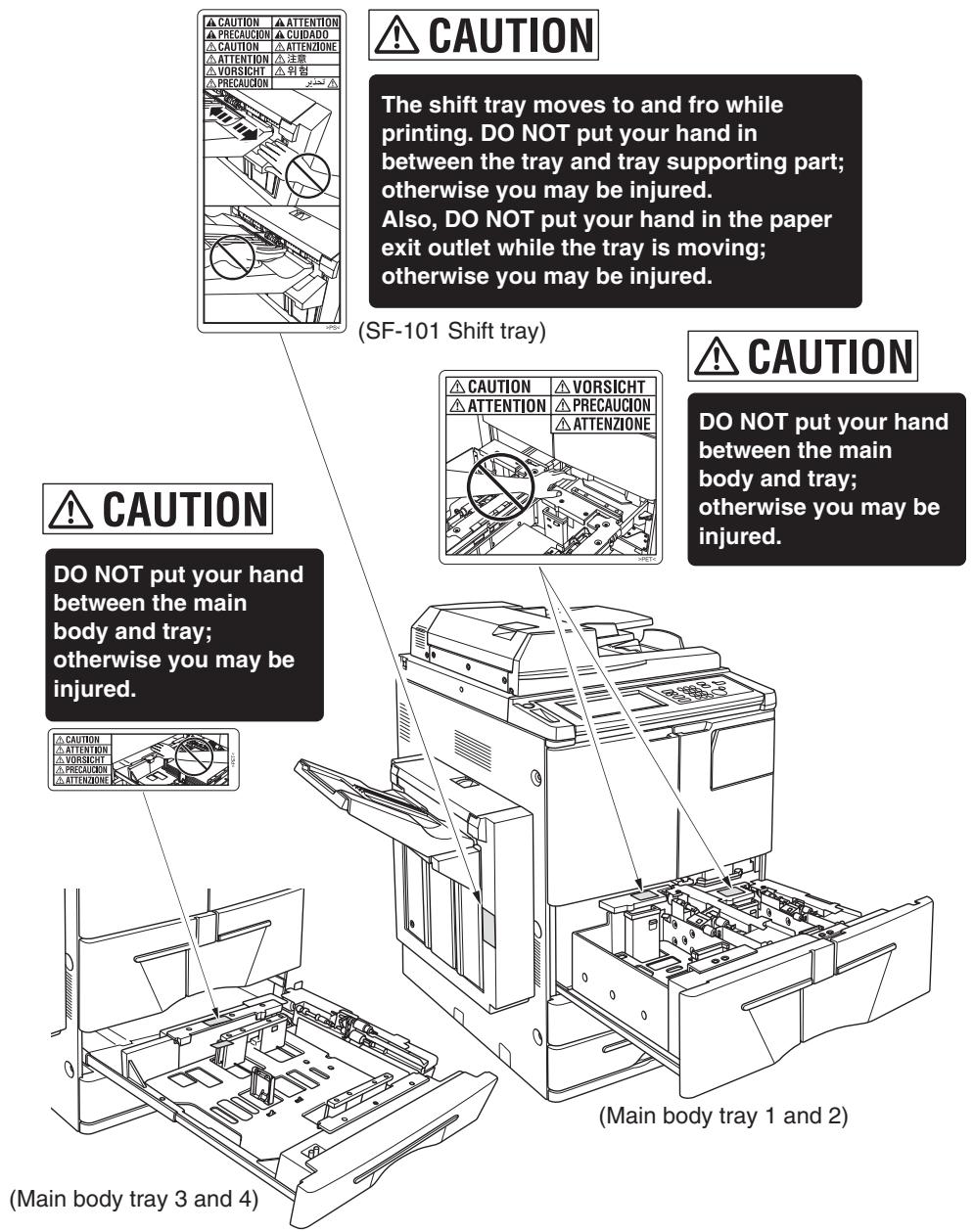

CAUTION
Burns or injury may occur from touching the areas detailed in the caution labels and caution indicators. Do not remove caution labels or indicators. If any caution label or caution indicator is soiled, please clean to make legible. If you cannot make them legible, or if the caution label or indicator is damaged, please contact your service representative.
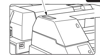
(Finisher with PI-110 Cover Sheet Feeder only)
CAUTION
DO NOT insert your finger into the bottom of the upper part of the feeder when returning to its original position; otherwise you may be injured.

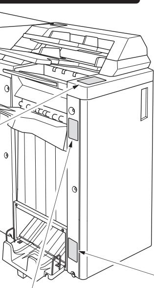
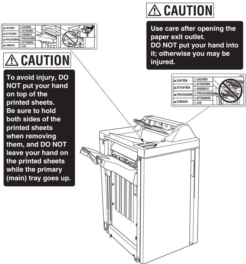
(FS-110/FS-210 Finisher)
CAUTION
To avoid injury, DO NOT put your hand on top of the printed sheets.
Be sure to hold both sides of the printed sheets when removing them, and DO
NOT leave your hand on the printed sheets while the primary (main) tray goes up.
(FS-110/210 Finisher)
CAUTION
Use care after opening the paper exit outlet. DO NOT put your hand into it; otherwise you may be injured.
(FS-210 Finisher only)
CAUTION
Inside the lower paper exit outlet is the roller drive unit. DO NOT put your hand into it; otherwise you may be injured.
(FS-111 Finisher)
The following indicators are used on the caution labels or in this manual to categorize the level of safety cautions.

DANGER:
Action highly liable to cause a death or serious injury.

WARNING:
Action liable to cause a death or serious injury.

CAUTION:
Action liable to cause minor injury, medium trouble or physical damage
If you find any of these indicators when removing jammed paper, adding toner, or reading the manual, be sure to follow the information.

Please Be Reminded!
If the safety cautions in the manual become illegible due to soilage, etc., please arrange a new copy from your service representative.
To ensure your safe use of the machine, the following describes the precautions you are required to observe without fail for the power source of the machine and during installation and routine handling. Be sure to read and observe them.
Power Source
CAUTION: Plug Socket
- A plug socket is limited in capacity. Use only a power source with the correct rating for the machine; otherwise, hazardous situations such as smoking or overheating may occur. See the following list to match the power supply and power consumption:
a) 230 ~V / 50 ~Hz : More than 10A
b) 230V / 60Hz : More than 10A
- Avoid multiple connections in the same outlet. Do not use multiple outlet adaptors.
CAUTION: Power Plug and Lead
- Be sure to insert the power plug firmly into the power socket. Otherwise an accident may occur as a result of smoking or overheating. If the inserted power plug is loose in the socket, even after it has been positively inserted, disconnect the plug and contact your electrical contractor.
- For plug cable equipment, that the socket-outlet shall be installed near the equipment and shall be easily accessible.
- Do not bend or crush the power lead. If your copier power lead is bent or damaged in any way, contact your service representative immediately. Do not attempt to repair it yourself, and do not continue to operate the copier. A damaged power lead may result in overheating, a short circuit, or fire.
- Do not bundle or coil the power lead of the copier. Otherwise an accident may occur as a result of overheating or fire.
- When using the power cord (inlet type) that came with this copier, be sure to observe the following precautions:
a. Make sure the copier-side power plug is securely inserted in the socket on the rear panel of the copier.
Secure the cord with a fixture properly.
b. If the power cord or sheath is damaged, replace with a new power cord (with plugs on both ends) specified by us.
If the power cord (inlet type) is not connected to the copier securely, a contact problem may lead to increased resistance, overheating, and risk of fire.
CAUTION: Connecting Multiple Loads to One Socket Outlet Prohibited
Never connect multiple loads to one socket outlet using a multi-outlet extension lead or branched socket. Otherwise an accident may occur as a result of overheating or fire.
CAUTION: Extension Lead
An extension lead must never be used with this machine.
Environment
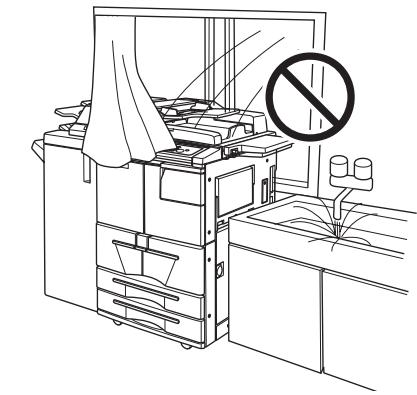
CAUTION: Prevention of Fire
Do not install near flammable materials, curtains and volatile combustibles, that can catch or cause fire.
CAUTION: Prevention of Short Circuit
Do not install the copier where it could be splashed with rain water, or water from a tap, to avoid a short circuit.
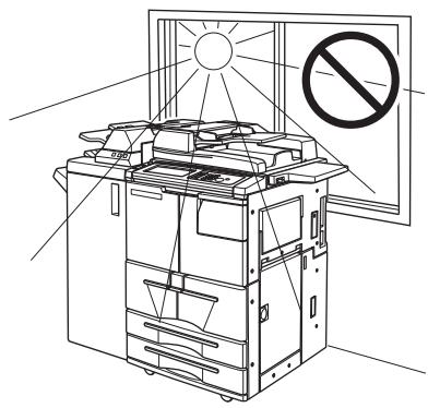
CAUTION: Temperature and Humidity
- Keep away from direct sunlight, heat sources such as stoves, cool air from an air conditioner and hot air from a heater.
- Avoid any environment that is outside the range shown below:
10 to 30^ in temperature
10 to 80% in humidity
CAUTION: Ventilation
- Maintain the installation place well-ventilated.
- Keep away from dust or corrosive gases. These materials may cause poor image quality.
- During the use of machine, the machine generates ozone but in an insufficient amount to cause any hazard to the human body.
However, if the machine is used in a poorly ventilated room, many copies are made, or plural copiers are used at the same time, an odour may be detected.
Ensure adequate ventilation for a comfortable working environment.
CAUTION: Vibration
Do not install on a floor which is subject to vibration or is not level.
CAUTION: Transportation
Be sure to contact your service representative when moving or transporting the machine. If you move the machine with the Hard disk drive or Memory unit installed, machine trouble may be caused by vibration.
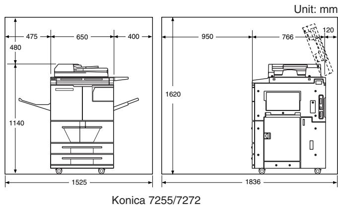
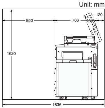
CAUTION: Installation Space
Allow sufficient space for facilitating copy operation, changing parts, and periodic inspection. Especially leave an adequate space behind the machine to let hot air out from the rear fan.
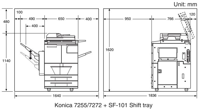

Please Be Reminded!
SF-101 Shift tray gradually goes down while printed materials output. DO NOT allow any object to interfere with the operation of the tray on the left side of the Shift tray, as any interference may cause damage to the Shift tray.
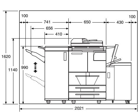
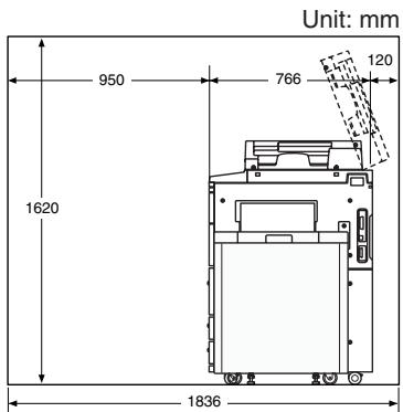
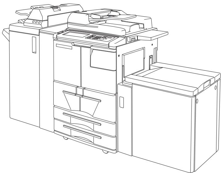
Konica 7255/7272 + FS-110 Finisher + LT-402 Large capacity tray
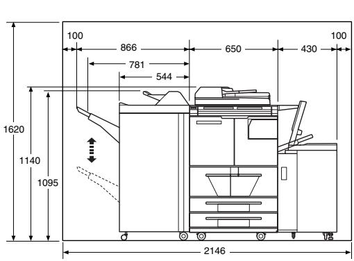
Konica 7255/7272 + FS-111 Finisher + LT-402 Large capacity tray
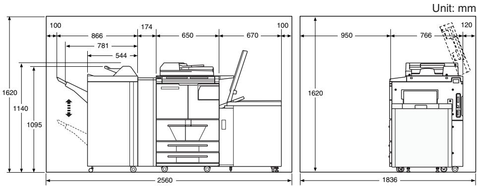
Konica 7255/7272 + PZ-108/PZ-109 Punching / Z-Folding unit + FS-111 Finisher + LT-412 Large capacity tray
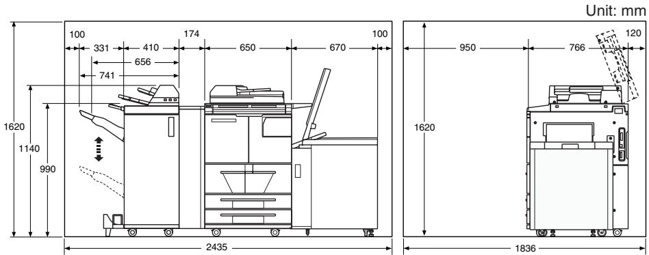
Konica 7255/7272 + PZ-108/PZ-109 Punching / Z-Folding unit + FS-210 Finisher + PI-110 Cover sheet feeder + LT-412 Large capacity tray

Please Be Reminded!
SF-101 Shift tray gradually goes down while printed materials output. DO NOT allow any object to interfere with the operation of the tray on the left side of the Shift tray, as any interference may cause damage to the Shift tray.
Precautions for Routine Handling
WARNING: High Voltage
DO NOT TOUCH the high voltage parts indicated with WARNING label or described in the manual.
CAUTION: Actions in Response to Troubles
- If the Service Call screen is displayed and copier operations cannot be continued any more, stop the operation to prevent any unexpected accident. Write down the report code as stated on the 2nd line of the message, then switch off the copier and disconnect from the power socket. Contact your service representative and inform them of the report code.
- Do not touch the high temperature parts indicated with CAUTION labels or described in the manual.
- Do not touch the inside of the machine for any other purpose than removing jammed paper or adding toner.
- If machine repair is necessary, be sure to contact your service representative. Never attempt to repair it by yourself.
- If any abnormal sound, smell or smoke comes from the machine, immediately stop using it, turn off the power switch, disconnect the power plug and contact your service representative.
- If the breaker trips or the fuse blows, turn off the power switch, reset the breaker or the fuse, and turn on the machine. If the same situation occurs again, contact your service representative.
- Insure the replacement fuse conforms with the rating of the power source. Never use a fuse with an incorrect rating.
CAUTION: Prevention of Fire
Do not use volatile combustibles such as a thinner or alcohol near the machine.
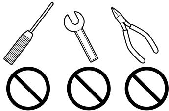
CAUTION: Prohibition of Machine Modification
Do not modify or remove any parts by yourself.

CAUTION: Prevention of Machine Troubles
- Do not drop small metallic objects such as paper clips or staples inside the machine.
- Do not place any heavy or hard objects such as a vase, books or ornaments on the machine.


CAUTION: Recommendation of Periodic Check
Be sure to check periodically the following points:
(1) The main lead or the power plug does not generate abnormal heat.
(2) The power plug is not inserted loosely or the lead is not cut or scratched.
(3) The earth wire is correctly connected.
(4) The power plug or the power outlet is not covered with dust.
If you find anything abnormal in the above items, stop using the machine and contact your service representative.

CAUTION: Toner
- Keep the toner cartridge away from children. The toner is nontoxic; however if you inhale or contact with eyes by accident, flush with water and seek medical advice.
- Do not throw the empty toner cartridge into a fire. If it is thrown into a fire, the toner may ignite and cause a dangerous situation.

CAUTION: Paper
- Check paper to be sure it is according to specifications outlined in Section 11.
- Do not use stapled paper or paper that conducts electricity (silver, carbon, etc.), otherwise an accident may occur as a result of fire.
- To avoid machine trouble, do not use heat-sensitive paper, coloured OHP film, or paper specifically designed for ink-jet printers, such as photo paper.

CAUTION: Power Saver and Weekly Timer
- During Power Saver mode the copier is still connected to the mains power supply and power is still applied to certain areas of the machine. To avoid any unexpected troubles turn the power OFF when not using the copier for long periods of time.
- When the Weekly Timer function is operating, turning power OFF will disable the function.
CAUTION: Inside the Booklet Mode Outlet
Inside the Booklet mode outlet is the roller drive unit. DO NOT put your hand into it, when removing the folded or stapled & folded sheet; otherwise you may be injured.
CAUTION: Finisher Paper Exit Outlet
To avoid injury when stapling large size copies, DO NOT put your hand into the open Paper Exit Outlet.
CAUTION: Fixing Unit
The Fixing unit is internally very hot. To avoid getting burned, DO NOT TOUCH. Be careful when withdrawing the fixing unit.
WARNING: Drum Unit
The drum unit has a high voltage generated. To avoid an electrical shock, DO NOT TOUCH.
CAUTION: Dispose of a Disused Copying Machine
Do not dispose of this copier yourself. Contact your service representative, who can arrange for its safe disposal. If you change the place of installation, please contact your service representative.
CAUTION: Paper Capacity for the Exit Tray
The exit tray capacity is max. 100 sheets. If a copy run of more than 100 is required, be sure to remove the copies from the exit tray before the maximum capacity is reached. Failure to do so will cause the copier to jam.
CAUTION: Finisher Paper Capacity
The FS-110/FS-111 Finisher is equipped with two exit trays, and FS-210 Finisher is equipped with three exit trays.
Select an exit tray and output mode on the Output Mode popup menu. To prevent paper misfeed, do not exceed the paper capacity of the Finisher.
When the total number of copies in the copy run exceeds the capacity stated in Section 11, be sure to unload the exit tray whilst the copier is still copying. Failure to do so will cause the copier to jam.
CAUTION: Finisher Primary (Main) Tray
When printed materials are removed from the primary (main) tray of FS-110/ FS-111/FS-210 Finisher, the tray goes up automatically. To avoid injury, DO NOT put your hand on top of the printed sheets. Be sure to hold both sides of the printed sheets when removing them, and DO NOT leave your hand on the printed sheets while the primary tray goes up.

CAUTION: SHIFT TRAY AND PAPER EXIT OUTLET
- The shift tray moves to and fro while printing. Do not put your hand in between the tray and tray supporting part; otherwise you may be injured.
- Do not put your hand in the paper exit outlet while the tray is moving; otherwise you may be injured.
SECTION
2
Machine Information
Machine Configuration, Turning On the Power and Loading Paper
Machine Configuration 2-2
Turning On the Main Power Switch and Power Switch 2-18
Loading Paper 2-24
Changing Paper Size of Tray 3 and 4. 2-34
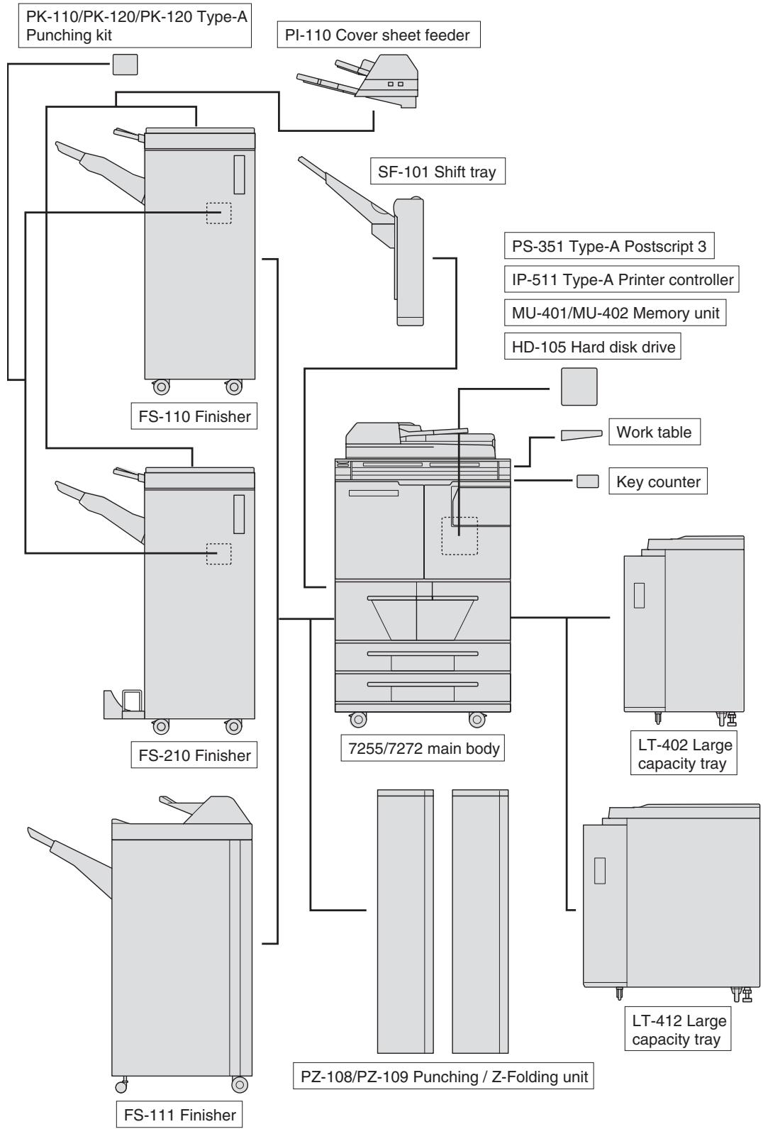
External Machine Items
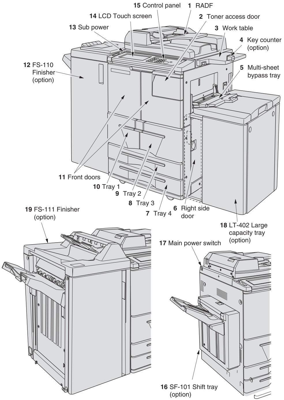
1 RADF (Reversing Automatic Document Feeder) automatically feeds multiple originals one at a time to the platen glass for copying.
2 Toner access door opens to allow replenishing of toner.
3 Work table provides a convenient workspace for documents both before and after copying.
4 Key counter (option) manages the number of copies made on the machine.
5 Multi-sheet bypass tray used for small quantity copying onto plain paper or special paper.
6 Right side door opens to allow removal of mishandled paper.
7 Tray 4 (universal tray) is user-adjustable and holds 500 sheets from A3 to A5.
8 Tray 3 (universal tray) is user-adjustable and holds 500 sheets from A3 to A5.
9 Tray 2 is service-adjustable and holds 1,000 sheets of A4 or B5.
10 Tray 1 is service-adjustable and holds 1,500 sheets of A4 or B5.

HINT
Tray 1, 2, 3, 4 and LCT are available for loading wide types of the regular sizes specified above.
11 Front doors open to the internal copier to allow clearing of mishandled paper.
12 FS-110 Finisher (option) sorts, staple-sorts, and groups into finished sets.
With PK-110/120/120 Type-A Punching kit (option) installed, file holes can be punched in the output copies.
With PI-110 Cover Sheet Feeder (option) installed, cover sheet paper can be inserted in the output copies.
13 Sub power switch turns copier power On/Off when pressed.
14 LCD Touch screen displays interactive operation screens.
15 Control panel controls copier operations.
16 SF-101 Shift tray (option) sorts and groups into finished sets, and offsets each set upon exit.
17 Main power switch turns machine power On/Off to operate it as copier/scanner/server/printer.
18 LCT (Large Capacity Tray LT-402) (option) holds 4,000 sheets.
19 FS-111 Finisher (option) sorts, staple-sorts, and groups into finished sets.
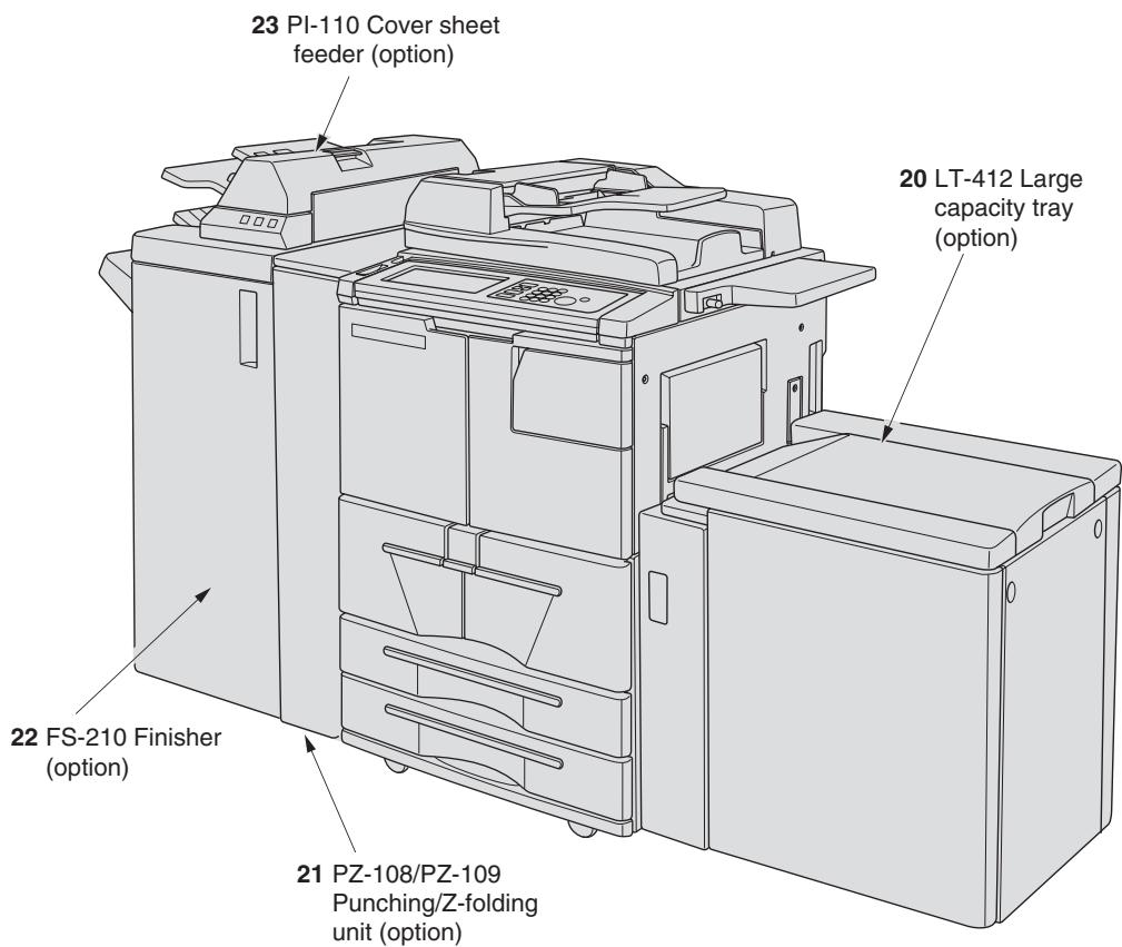
20 LCT (Large capacity tray LT-412) (option) holds 4,000 sheets.
21 PZ-108/PZ-109 Punching / Z-Folding unit (option) punches file holes and/or Z-folds the output copies.
22 FS-210 Finisher (option) sorts, staple-sorts, and groups into finished sets, folds or staple & folds copies into booklet-styled sets, and also folds max. 3 copies in three. With PK-110/120/120 Type-A Punching kit (option) installed, file holes can be punched in the output copies.
23 PI-110 Cover sheet feeder (option) loads cover sheet paper and feeds the sheet as cover.
Internal Machine Items
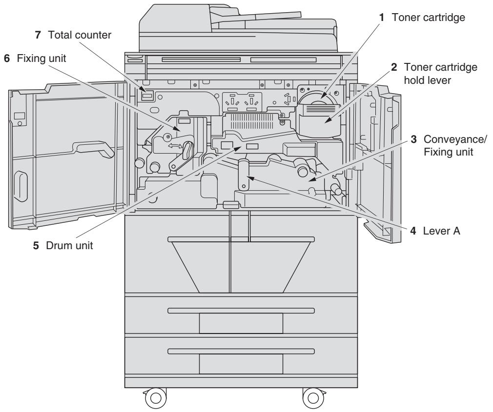
1 Toner cartridge holds toner and is to be replaced when supplying toner.
2 Toner cartridge holder lever can be pulled forward to withdraw the toner cartridge holder for replacing the toner cartridge.
3 Conveyance/Fixing unit passes the paper through the drum unit, and fuses the toner onto the copy paper, and is to be withdrawn for removal of mishandled paper.
4 Lever A can be moved to withdraw the conveyance fixing unit for removal of mishandled paper.
5 Drum unit forms the copy image.
6 Fixing unit fuses the toner onto the copy paper.
7 Total counter indicates the total number of copies and prints made.
Standard/Optional Equipment
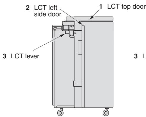
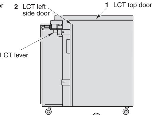
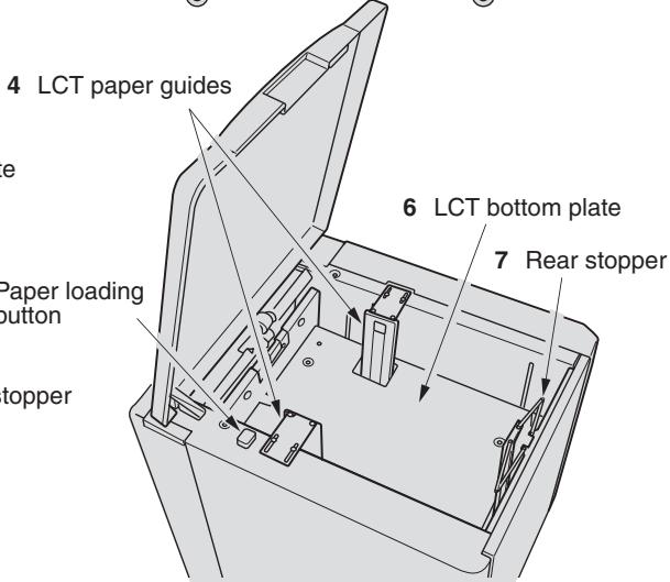
LT-402/LT-412 Large Capacity Tray
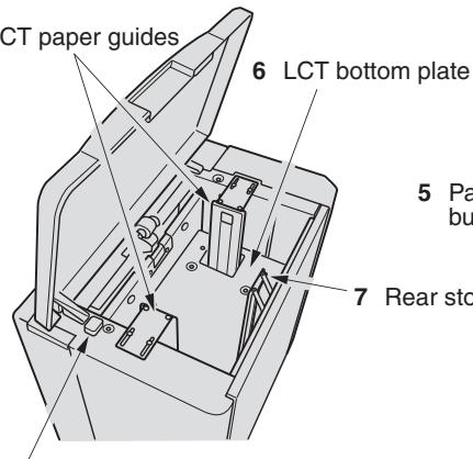
4 LCT paper guides
5 Paper loading button
LT-402 Large capacity tray
LT-412 Large capacity tray
1 LCT top door opens to allow paper loading.
2 LCT left side door opens to allow removal of mishandled paper.
3 LCT lever can be moved downward to ease removal of mishandled paper.
4 LCT paper guides hold copy paper to fix the position.
5 Paper loading button is pressed to lower the bottom plate to allow loading paper.
6 LCT bottom plate goes up automatically when paper supply becomes low, and goes down when the paper loading button is pressed.
7 Rear stopper fixes the rear end of copy paper.
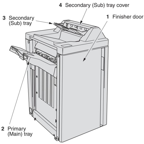
FS-110/FS-210 Finisher (+PK-110/120/120 Type-A Punching Kit)

1 Finisher door opens to the internal Finisher to allow clearing mishandled paper, replenishing staples, and emptying waste basket of Punching kit.
2 Booklet mode outlet (FS-210 Finisher only) ejects finished copied sets when selecting Fold mode, Stitch & Fold mode, or Three-fold mode.
3 Booklet tray (FS-210 Finisher only) holds sets output in Fold mode, Stitch & Fold mode, or Three-fold mode.
4 Primary (Main) tray holds sets output in Non-sort mode, Sort mode (offset), Staple-sort mode, or Group mode (offset).
5 Secondary (Sub) tray holds sets output in Non-sort mode or Group mode with face down/up mode.
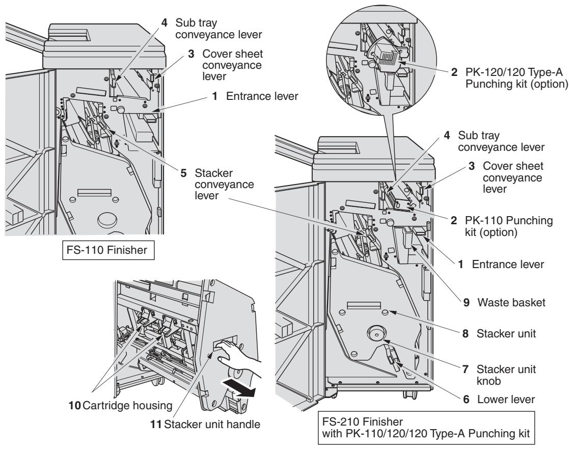
1 Entrance lever opens downward to remove mishandled paper.
2 PK-110/120/120 Type-A Punching kit (option) punches file holes in the output copies.
3 Cover sheet conveyance lever opens to remove mishandled paper.
4 Sub tray conveyance lever opens to remove mishandled paper.
5 Stacker conveyance lever opens to remove mishandled paper.
6 Lower lever opens to remove mishandled paper.
7 Stacker unit knob can be turned to ease removal of mishandled paper from the Stacker unit.
8 Stacker unit folds or staples & folds copies into booklet-styled sets, and also folds max. 3 copies in three.
9 Waste basket holds waste paper punched out.
10 Cartridge housing holds staple cartridge and is to be replaced when supplying staples.
11 Stacker unit handle withdraws unit to allow removal of mishandled paper and replacement of staple cartridge.
FS-111 Finisher
1 Finisher door opens to the internal Finisher to allow clearing mishandled paper and replenishing staples.
2 Primary (Main) tray holds sets output in Non-sort mode, Sort mode (offset), Staple-sort mode, or Group mode (offset).
3 Secondary (Sub) tray holds sets output in Non-sort mode or Group mode with face down/up mode.
4 Secondary (Sub) tray cover opens to allow clearing mishandled paper.
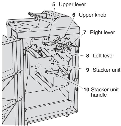
5 Upper lever opens upward to remove mishandled paper.
6 Upper knob can be turned to ease removal of mishandled paper.
7 Right lever opens to remove mishandled paper.
8 Left lever opens to remove mishandled paper.
9 Stacker unit holds stapler.
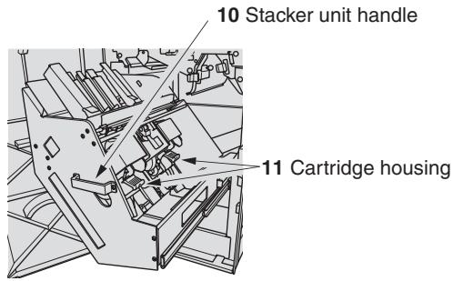
10 Stacker unit handle withdraws unit to allow removal of mishandled paper and replacement of staple cartridge.
11 Cartridge housing holds staple cartridge and is to be replaced when supplying staples.
PI-110 Cover Sheet Feeder
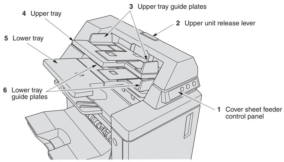
1 Cover sheet feeder control panel controls cover sheet feeder operations.
2 Upper unit release lever can be moved to slide the upper unit of cover sheet feeder for removal of mishandled paper.
3 Upper tray guide plates hold cover sheets to fix the position.
4 Upper tray holds cover sheets for use in cover sheet output mode.
5 Lower tray holds cover sheets for use in cover sheet output mode or a copied set in manual staple/punch/three-fold mode.
6 Lower tray guide plates hold cover sheets to fix the position.
PZ-108/PZ-109 Punching / Z-Folding Unit
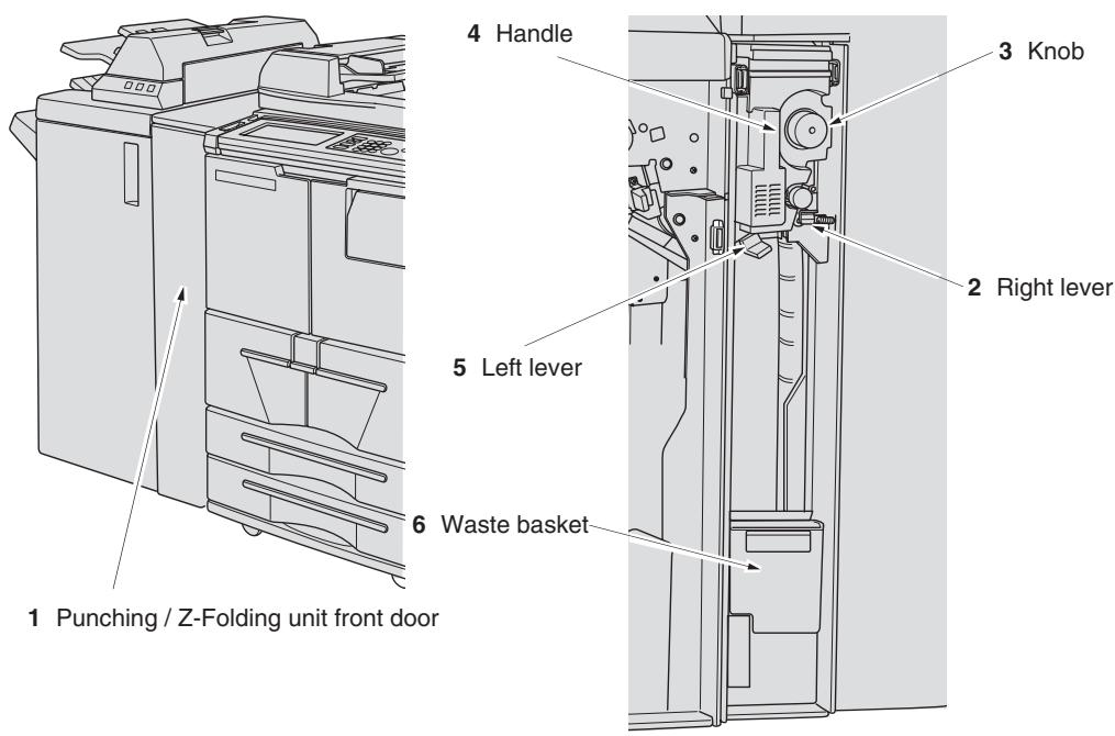
1 Punching / Z-Folding unit front door opens to allow removal of mishandled paper or waste paper.
2 Right lever opens to allow removal of mishandled paper.
3 Knob can be turned to ease removal of mishandled paper.
4 Handle can be withdrawn to allow removal of mishandled paper.
5 Left lever opens to allow removal of mishandled paper.
6 Waste basket holds waste paper punched out.
SF-101 Shift Tray
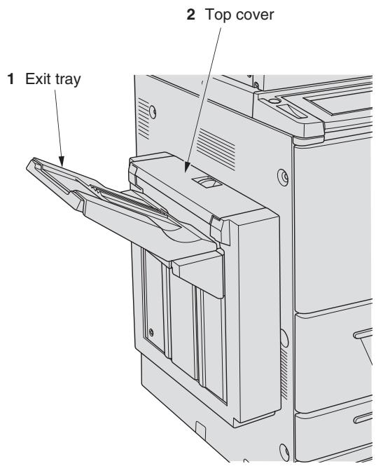
1 Exit tray holds sets output in Non-sort mode, Sort mode (offset), or Group mode (offset).
2 Top cover opens to allow clearing mishandled paper.
Control Panel Layout
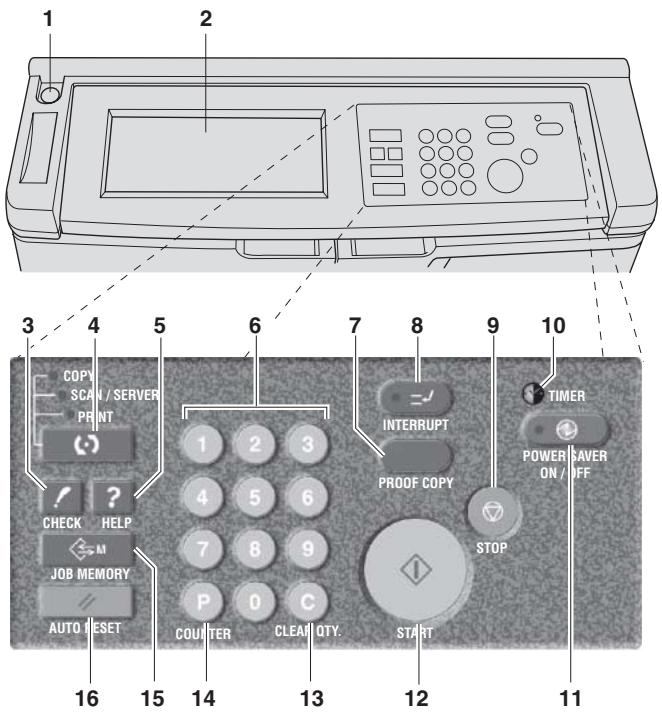
1 Sub power switch turns copier power On/Off when pressed.
2 LCD TOUCH SCREEN displays machine and copying status, help information, interactive screens, and touch keys for selecting all functions.
3 CHECK displays a screen showing all settings that are selected for the current job.
4 MODE switches the machine operation mode to copy, scan/server, and print.
5 HELP displays a screen with help for the currently selected function, or to access the Key Operator Mode Screen.
6 KEYPAD enters numeric values.
7 PROOF COPY outputs a single set of copies to confirm whether the current settings are selected properly.
8 INTERRUPT stops copying in progress to allow copying from the platen glass.
9 STOP stops the copying sequence; deletes the stored memory.
10 TIMER lights when the timer function is set.
11 POWER SAVER ON/OFF activates power-saving mode for times when the copier is inactive, or activates Timer Interrupt mode when Weekly Timer function is active.
12 START activates copying or scanning.
13 CLEAR QTY. allows resetting of print quantity.
14 [P] (counter) displays the Counter Screen or accesses programming modes for setting special functions.
15 JOB MEMORY displays screens for selecting job store/recall functions.
16 AUTO RESET restores copier to automatic mode settings or to Key Operator settings.

HINT
The control panel of this machine can be slightly lowered to ensure easy access by anyone, regardless of the physical or positional status of the operator. Your authorized service representative can make this setting for you.
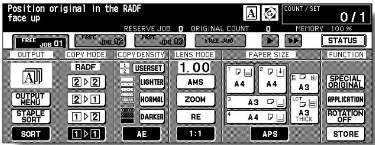
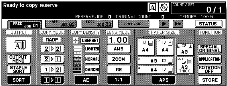
Basic Screen
The Basic Screen displays when copying operation becomes available after warm-up.
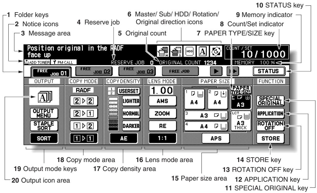
1 Folder keys
FREE JOB is selected to specify a copy job conditions.
When scanning starts, FREE JOB changes to SCAN JOB, then changes to PRINT JOB when the machine starts printing.
2 Notice icons
ADD TONER: ADD TONER icon is displayed when toner supply becomes low.
PMCALL: PM CALL icon is displayed when preventive maintenance is due.
3 Message area displays the machine status and procedure required at that time.
4 Reserve job counts the reserve jobs already specified.
5 Original count counts the original pages placed in the document feeder as they are scanned.
6: Master icon is displayed when the TANDEM key is selected on the Output Mode popup menu.
: Sub icon is displayed when the copier operates in tandem with the primary (master) copier.
HDD: HDD icon is displayed when using Image Store & Output mode of Server function.
: Rotation icon is displayed when Rotation automatically functions.
A V A
Original direction icon indicates the original direction specified on the Special Original popup menu.
7 PAPER TYPE/SIZE key is touched to specify the type and size of the paper loaded in the Multi-sheet bypass tray.
8 Count/Set indicator indicates the print quantity entered from the control panel keypad, and also indicates the print count on the left of the set count while printing.
9 Memory indicator indicates the remaining memory available for the next operation.
10 STATUS key is touched to view the current job status, to change the printing order of reserve jobs, or to cancel printing a reserve job.
11 SPECIAL ORIGINAL key is touched to specify the condition of originals to be scanned.
12 APPLICATION key is touched to select various application functions.
13 ROTATION OFF key is touched to release the Rotation function.
14 STORE key is touched to store scanned images into memory.
15 Paper size area is used to select the desired paper size or APS.
16 Lens mode area is used to select the desired magnification ratio.
17 Copy density area is used to specify the desired exposure level.
18 Copy mode area is used to select the copy mode (1-1, 1-2, 2-1, or 2-2).
19 Output mode keys are used to specify the desired output mode.
20 Output icon area displays the appropriate output icon according to the selected output mode.
Turning On the Main Power Switch and Power Switch
This machine is equipped with two power switches.
To Turn On the Power
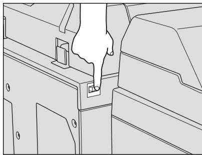
1. Turn ON the main power switch.
The main power switch is located on the rear left side of the main body.

Please Be Reminded!
When turning the main power switch OFF then ON, wait for 10 seconds or longer before turning it ON again; otherwise the copier may not function normally.
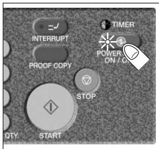
2. Turn ON the sub power switch.
The sub power switch is located on the far left side of the control panel.

3. The Wake-up Screen and Warm-up Screens will be displayed.
Please wait for a while
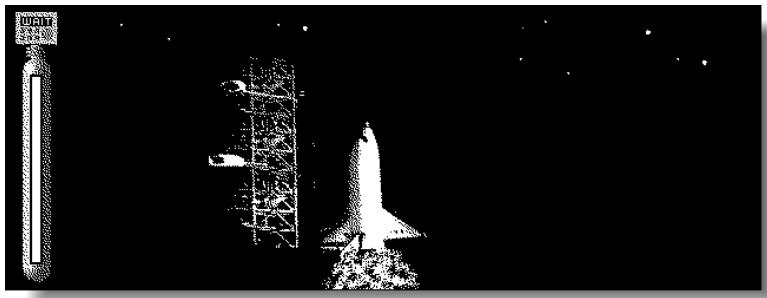
A few seconds after the Wake-up Screen appears in the LCD touch screen, seven types of Warm-up Screens will be displayed in succession for approx. 5 minutes (7255) / 6 minutes (7272).

HINT
Setting reserve job is available while the machine is warming up. Touch the LCD screen to change the Warm-up Screen to the Basic Screen, then check that the message "Ready to copy reserve" is displayed on the Basic Screen. See p. 3-7 to p. 3-8.
4. The Basic Screen will be displayed.
The message on the Basic Screen will inform you that copying job is now available.

FOR DETAILS
- When the initial settings are changed by the Key Operator, the modified conditions will be displayed on the Basic Screen.
- When "Enter E.K.C. password" is displayed, enter your password to use the machine.
To Turn Off the Power
1. Turn OFF the sub power switch.
The sub power switch is located on the far left side of the control panel. The touch screen and all the LEDs on the control panel will go out.
2. Turn OFF the main power switch.
The main power switch is located on the rear left side of the main body.

FOR DETAILS
- The main power switch is not required to be turned off usually.
- When the machine is under control of the Weekly Timer function, turning off the main power switch will deactivate the function.
Reducing the Power in Standby Mode (Auto Low Power)
This function automatically lowers the power after a specified period (initially 15 minutes) of copier inactivity. When activated, the LCD screen will go off.

HINT
The Auto Low Power function can be set to 5 minutes/ 10 minutes/ 15 minutes/ 30 minutes/ 60 minutes/ 90 minutes/ 120 minutes/ 240 minutes in the Key Operator mode. For the Key Operator setting, see p. 13-38.
To start a copying job, press any key on the control panel.
The Auto low power will be released and the LCD screen will be displayed.

FOR DETAILS
- If the Auto Shut-Off function activates at the same time, the power will be turned off.
- The LCD screen will not go off during a duplex copying job or when the Jam Position Screen is displayed.
Shutting Off Automatically (Auto Shut-Off)
This function automatically shuts off the power after a specified period (initially 90 minutes) of copier inactivity.
To start a copying job, press [POWER Saver ON/OFF].
The copying operation will become available.

HINTS
- The Auto shut-off can be set for 30 minutes/ 60 minutes/ 90 minutes/ 120 minutes/ 240 minutes in the Key Operator mode. For the Key Operator setting, see p. 13-38.
- When "Timer interrupt mode / Enter password" is displayed after pressing [POWER Saver ON/OFF], see p. 7-2 and follow the procedure to continue.
Shutting Off / Reducing the Power Manually
Follow the procedure below to shut off the power manually.

HINT
The machine is initially set to activate the Manual Shut-Off function. The Manual Low Power can be selected in the Key Operator setting. See p. 13-39 to p. 13-46.
1. Press [POWER Saver ON/OFF] for one second or longer, then release it.
![KONICA MINOLTA 7255 - Press [POWER Saver ON/OFF] for one second or longer, then release it. - 1](/content/2025/01/139764/images/219e8f3b4dd7dc7fd036cfcac28e77be156eb2494963cf19aa4b5c96c368a783.jpg)
![KONICA MINOLTA 7255 - Press [POWER Saver ON/OFF] for one second or longer, then release it. - 2](/content/2025/01/139764/images/1695509f59a03bdedbf0ca4f97e485a808b70e31ca93aea72656b19cf5256099.jpg)
FOR DETAILS
If the Manual Low Power is selected in the Key Operator setting, the machine automatically activates the Low Power mode before releasing [POWER Saver ON/OFF].
2. The Shut-Off mode will be activated.
The [POWER SAVER ON/OFF] LED will be lit and all other LEDs and the LCD screen will be turned off.

FOR DETAILS
Be sure to press [POWER Saver ON/OFF] for one second or longer, otherwise the following message will be displayed and the Shut-Off (Low Power) mode will not be activated.
Press POWER SAVER more than one second, then release it for shut off mode
Press POWER SAVER more than one second for low power mode
To release the mode, press [POWER Saver ON/OFF]. The machine will be available for copying operation.
Entering an EKC Password (EKC)
The Electronic Key Counter (EKC) allows the Key Operator to monitor all copying activities by controlling EKC password accounts. Copy quantity limits for specific accounts can be set.
The EKC is not factory-set. An EKC password is required only when the EKC is activated; a User Password is assigned; and "Enter E.K.C. password" is displayed on the touch screen.
Copying will be available by following procedure.

HINT
For details of the EKC setting, see p. 13-15 to p. 13-21.
1. Enter EKC password.
Enter your 8-digit EKC password, using the keypad.

HINT
For setting an EKC password, see p. 13-17 to p. 13-19.

FOR DETAILS
If an invalid EKC password is entered, continue by entering the correct password.
2. Press [START].
Your current copy count and copy limit will be displayed for 3 sec.
Current count / limit
018888/025000
3. Start a copying job.
When the message changes to "Ready to copy", copying job is available on the machine.

FOR DETAILS
When your copy count reaches the copy limit, the message "Copy limit reached" will be displayed. In that case, contact the Key Operator to reset your copy limit.
4. Press [C] while pressing [P] .
The initial state will be restored, with the message "Enter E.K.C. password" displayed on the screen.
A paper indicator is shown on each tray key of the Basic Screen to indicate the paper level of the tray. (Six levels are provided:
When paper in a tray becomes empty, the indicator “ ” appears on the tray key.
![KONICA MINOLTA 7255 - Press [C] while pressing [P] . - 1](/content/2025/01/139764/images/f49bcd4e1ee5996f2802c263e61b05b9070c129bf5eecd60f9960937fbff4418.jpg)
Follow the procedure below to supply the empty tray with copy paper.
![KONICA MINOLTA 7255 - Press [C] while pressing [P] . - 2](/content/2025/01/139764/images/5e30aa1d936c7d0d211927ce6eeb38037cacb7dda88bd9087e8b7cb1c67871aa.jpg)
HINT
When Thick or Thin is displayed on the tray key of the Basic Screen, be sure to load the specified paper; otherwise mishandled paper may occur. For details, see p. 13-23 to p. 13-24.
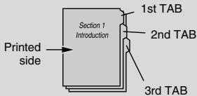
When TAB is displayed, see p. 2-31 for loading tabbed sheets.
Loading Paper in Tray 1 and 2
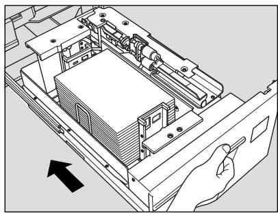
1. Withdraw tray 1 or 2.

HINT
See p. 2-2 to check positions of each tray.

Please Be Reminded!
Do not withdraw the tray forcibly; otherwise you may be injured.
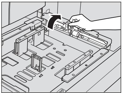
2. Open the paper feed roller.
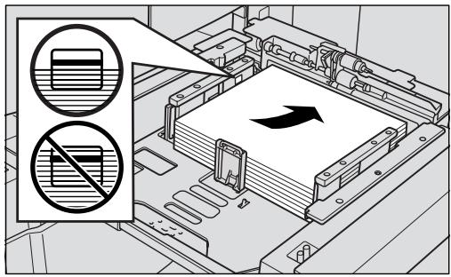
3. Place paper on the tray with the curl side turning up.
Load paper aligning it to the right side of the tray.

Please Be Reminded!
- Do not load above the limit indicated on the side guide plate.
- Be sure that the rear guide plate is correctly positioned according to the paper size to be loaded; otherwise machine trouble may occur.
4. Push in the tray until it locks into place.
The indicator “ ” on the tray key will change to “ ”.

Please Be Reminded!
Do not bump the tray into the main body; otherwise machine trouble may be caused.
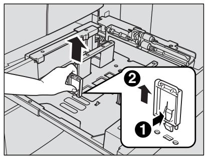
Loading Paper in Tray 3 and 4
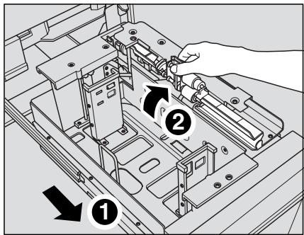
1. Withdraw tray 3 or 4.

HINT
See p. 2-2 to check positions of each tray.

Please Be Reminded!
Do not withdraw the tray forcibly; otherwise you may be injured.
2. Open the paper feed roller.
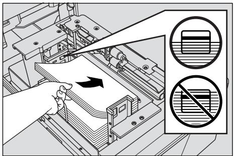
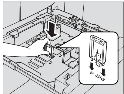
3. Place paper on the tray with the curl side turning up.
Load paper aligning it to the right side of the tray.

Please Be Reminded!
- Do not load above the limit indicated on the side guide plate.
- Be sure that the rear guide plate is correctly positioned according to the paper size to be loaded; otherwise machine trouble may occur.
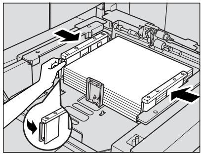
4. While pressing the release knob, move the rear side guide plate against the paper.
Release the release knob to lock the side guide plate.
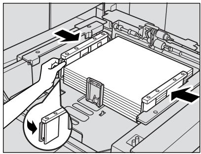

Please Be Reminded!
Be sure that the side guide plates are securely aligned to the paper; otherwise the machine cannot detect the correct paper size, or copies may not be punched in position.
5. When paper is seated properly, close the paper feed roller.
6. Push in the tray until it locks into place.
The indicator “ ” on the tray key will change to “ ”.

Please Be Reminded!
Do not bump the tray into the main body; otherwise machine trouble may be caused.
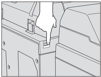
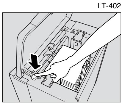
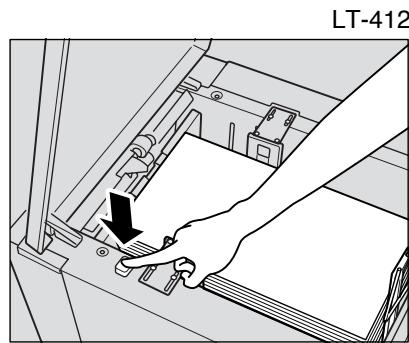
Loading Paper in LCT (LT-402/LT-412)
- Open the LCT top door.
- Press the paper loading button to lower the LCT bottom plate.
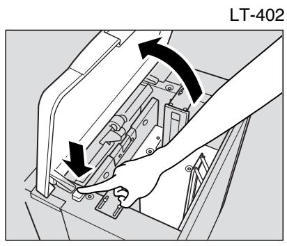
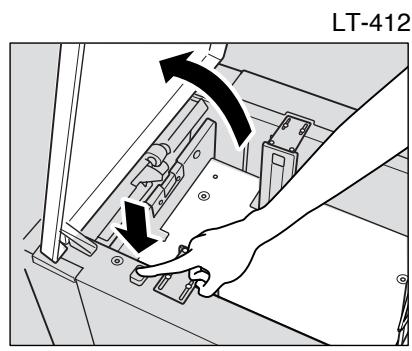

Please Be Reminded!
Be sure that both main power switch and sub power switch are turned on before loading paper in the LCT. Without the power turned on, the LCT bottom plate will not function.
- Load the paper into the LCT with the paper curl turning downward, making sure it is the same size as the tray has been set to.
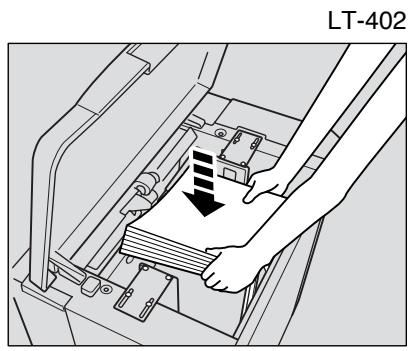
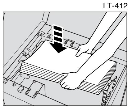

Please Be Reminded!
Be sure to load only the paper size fixed for the LCT. To change the paper size of the LCT, contact your service representative.
4. Repeat the steps 2 and 3 until the bottom plate will not go down any more.

Please Be Reminded!
- Do not load above the red line on the side guide plates.
- Be sure that the rear stopper is correctly positioned according to the paper size to be loaded; otherwise machine trouble may occur.
5. Close the LCT top door.
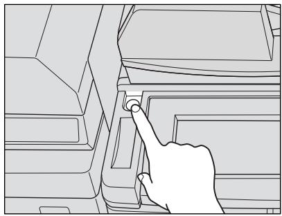
Loading Paper in Multi-Sheet Bypass Tray
- Open the Multi-sheet bypass tray located on the right side of the copier.
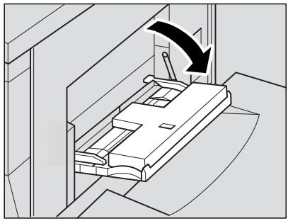
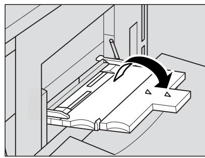
- Load copy paper, and adjust the paper guides to the paper size.
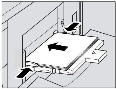
The loaded paper size will be indicated on the bypass tray key of the Basic Screen.

Please Be Reminded!
Load OHP film or thin/thick paper one sheet at a time; or, stack paper, up to 100 sheets 80g / m^2
- When copying is completed, close the Multi-sheet bypass tray.

CAUTION
Do not use stapled paper or paper that conducts electricity (silver, carbon, etc.), otherwise an accident may occur as a result of fire.

Please Be Reminded!
To avoid machine trouble, do not use heat-sensitive paper, coloured OHP film, or paper specifically designed for ink-jet printers, such as photo paper.
Loading Tabbed Sheets in Tray 3 or 4
When TAB is displayed on the tray key of the Basic Screen, follow the procedure below to supply the tray with tabbed sheets.

HINT
The tray paper type can be specified in the Key Operator setting. For details, see p. 13-23 to p. 13-24.

FOR DETAILS
- Service can set the tray 1 or 2 to have the tabbed sheets loaded. Contact your service representative, if desired.
- The tab extension width should be 12.5 mm or less.
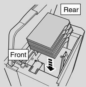
- Withdraw tray 3, or 4.
- Open the paper feed roller.
- Position the rear guide plate according to the size of the tabbed sheets to be loaded.

HINT
See p. 2-34 for details on positioning the rear guide plate.
- Place the tabbed sheets on the tray as illustrated above.
- While pressing the release knob, move the rear side guide plate against the paper.
- Close the paper feed roller, then push in the tray until it locks into place. 2-31
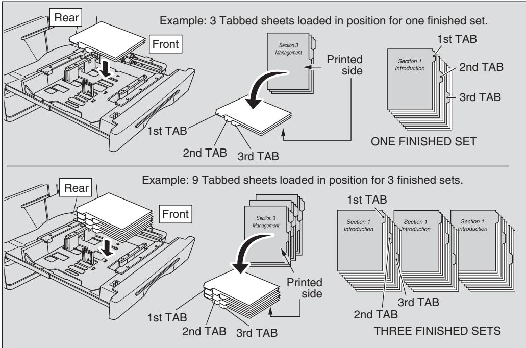
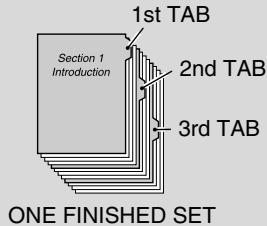
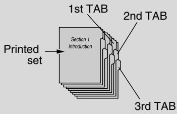
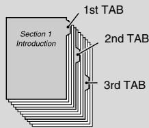
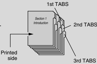
Loading Tabbed Sheets in LCT (LT-402/LT-412)
Example: 3 Tabbed sheets loaded in position for one finished set.

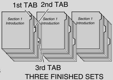
Example: 9 Tabbed sheets loaded in position for 3 finished sets.

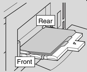
FOR DETAILS
- The tab extension width should be 12.5 mm or less.
-
To load the tabbed sheets into LCT, contact your service representative for positioning the rear stopper for the paper size to be loaded.
-
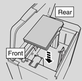
Open the LCT top door.
- Press the paper loading button to lower the LCT bottom plate.
- Load the tabbed sheets into the LCT as illustrated above.
- Close the LCT top door.
Loading Tabbed Sheets in Multi-Sheet Bypass Tray
Example: 3 Tabbed sheets loaded in position for one finished set.
ONE FINISHED SET
Example: 9 Tabbed sheets loaded in position for 3 finished sets.
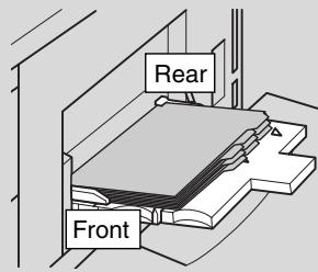

3 FINISHED SETS

FOR DETAILS
The tab extension width should be 12.5mm or less.
- Open the Multi-sheet bypass tray located on the right side of the copier.
- Load tabbed sheets as illustrated above.
- Adjust the paper guides to the paper size.
- Specify the paper type as TAB for the Multi-sheet bypass tray.

HINT
See p. 3-29 to p. 3-32 for specifying the paper type of the Multi-sheet bypass tray.
The main body trays 3 and 4 are user-adjustable. Change the paper size of the tray according to the procedure below.
- Withdraw the tray of the size to be changed.
- Open the paper feed roller.
- Remove the rear guide plate while pressing the knob, then insert it into the position designated for your desired paper size.
The rear guide plate positions are marked on the tray base plate.

Please Be Reminded!
Be sure to insert the rear guide plate into the position of the paper size to be set; otherwise machine trouble may occur.
- Stack paper, then move the rear side guide plate against the paper.
Press the release knob to move the rear side guide plate, then release it to lock.
- Close the paper feed roller, then push in the tray until it locks into place.
The tray key on the Basic Screen will indicate the paper size currently specified.
SECTION
3
Copying Operations
How to Make a Basic Copy
Positioning Originals 3-2
Setting Print Quantity 3-6
Setting Job During Warm-up 3-7
To Stop Scanning/Printing 3-9
Selecting Paper Size 3-10
Selecting Magnification Ratio (Lens Mode) 3-14
Selecting Density Level 3-18
Making Double-Sided Copy (1-2, 2-2) 3-21
Making Single-Sided Copy from Double-Sided Originals (2-1)......3-27
Copying Using Special Paper (Multi-Sheet Bypass Tray) 3-29
Copying Using Memory 3-33
Output Mode for Machine without Finisher 3-41
Output Mode for Machine with Finisher 3-44
Output Mode for Machine with Shift Tray 3-50
Selecting Binding Mode 3-53
Recalling Previous Job Settings 3-54
Checking Feature Selections and Proof Copying 3-55
Interrupt Copying 3-59
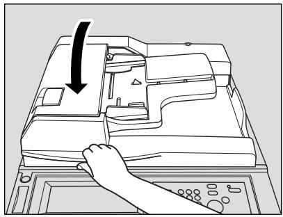
Positioning Originals in RADF
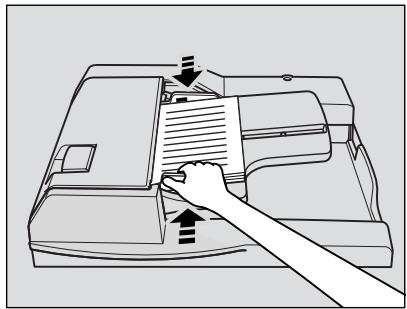
The document feeder (RADF) automatically feeds up to 100 originals directly to the platen area, starting with the top sheet. The RADF should only be used for unstapled, smooth, flat originals.
Positioning originals in Normal mode
1. Arrange originals in order.

Please Be Reminded!
- Before placing originals in the tray, be sure the document feeder is closed fully. Once closed, do not open the document feeder, otherwise the selected copy conditions may be altered automatically.
- Be sure not to use unsuitable RADF originals. See p. 11-8 for details.
2. Position original(s) FACE UP in the document feeder tray.
Place two-sided originals with page one FACE UP. Up to 100 originals can be set at a time.
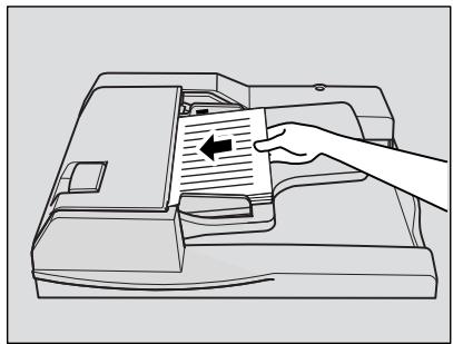

Please Be Reminded!
- Do not set more than 100 originals or over the red line indicated on the paper guides; otherwise a paper misfeed will occur.
- If the number of originals exceeds 100, divide them into blocks not exceeding 100 sheets, then load them from the block with the first page. See p. 3-33 to p. 3-34.
3. Adjust paper guides.
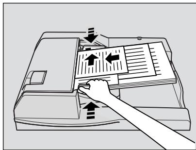
Positioning originals in Mixed original mode
Mixed size originals can be copied together from the document feeder.

HINT
To use the Mixed original mode, see procedure on p. 8-8 to p. 8-9.
1. Arrange originals in order.
Arrange the mixed size originals as illustrated below.
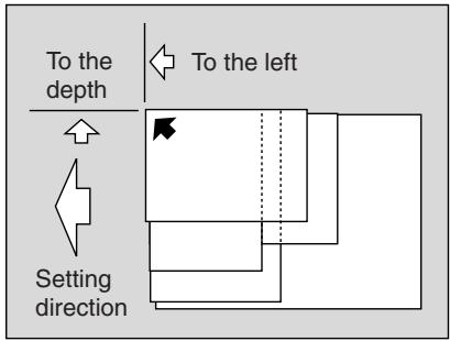

Please Be Reminded!
- Before placing originals in the tray, be sure the document feeder is closed fully. Once closed, do not open the document feeder, otherwise the selected copy conditions may be altered automatically.
- Be sure not to use unsuitable RADF originals. See p. 11-8 for details.

HINT
See p. 11-10 for available combinations of mixed originals.
2. Position mixed originals FACE UP, aligned with the left rear side of the document feeder tray.
Place two-sided originals with page one FACE UP.
Up to 100 originals can be set at a time.
3. Adjust paper guides.
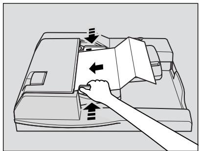
Positioning originals in Z-Folded original mode
Z-Folded original mode detects the folded original size without using the size detection sensor of the RADF.

HINT
To use the Z-Folded original mode, see procedure on p. 8-10 to p. 8-11.
1. Arrange originals in order.
2. Position original(s) FACE UP in the document feeder tray.
Place two-sided originals with page one FACE UP. Up to 100 originals can be set at a time.

Please Be Reminded!
- Before placing originals in the tray, be sure the document feeder is closed fully. Once closed, do not open the document feeder, otherwise the selected copy conditions may be altered automatically.
- Be sure not to use unsuitable RADF originals. See p. 11-8 for details.
3. Adjust paper guides.
Positioning Original on Platen Glass
Use the platen glass when originals are not suitable for use with the document feeder, e.g., when size is incompatible, or when originals are folded, stapled, torn, or in generally poor condition.
1. Raise the document feeder.
Place original FACE DOWN in the left rear corner, aligning the edge with the left measuring guide.
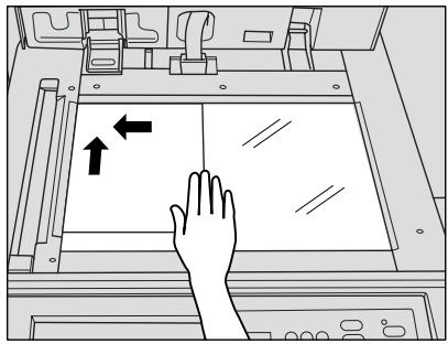
- Gently close the document feeder to prevent the original from shifting on the glass.

Please Be Reminded!
When selecting Dual Page, Non-Image Area Erase, AUTO mode in Repeat, or AUTO Layout, DO NOT CLOSE the document feeder. For details on each function, see Section 9.

CAUTION
Do not place too heavy originals, or do not press strongly when thick original is placed and is under pressure of RADF; otherwise the glass may be broken and you may be injured.
This section describes how to set or change print quantity.
To Set Print Quantity
The copier is initially set to copy the original set in amounts determined by the print quantity setting, then outputs sorted sets.
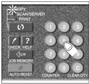
1. Enter the desired print quantity from the control panel keypad.
Entered quantity will be displayed on the touch panel.
To Change Print Quantity
Follow the procedure below to change the print quantity which has been already entered.
1. Press [C (CLEAR QTY.)].
![KONICA MINOLTA 7255 - Press [C (CLEAR QTY.)]. - 1](/content/2025/01/139764/images/15b96689d1a687f684ffe52f307aeda2e5d1fee49f1cfb35c1c5ac2075ba8506.jpg)
![KONICA MINOLTA 7255 - Press [C (CLEAR QTY.)]. - 2](/content/2025/01/139764/images/7121a3b1055723cac5489828624519250dd7f4129bd9ed61022434b068f09a5c.jpg)
The quantity displayed on the touch panel will return to 1.
2. Enter the correct quantity.
Entered quantity will be displayed on the touch panel.
While the copier is warming up after power is turned on, select copy conditions and start scanning so that the copier may start printing immediately the copier engine is ready.
1. Turn on the main power and power switches of the machine.
A few seconds after the Wake-up Screen appears in the LCD touch panel, seven types of Warm-up Screen display in succession for approx. 5 minutes (7255) / 6 minutes (7272).

2. Touch the LCD panel to change the Warm-up Screen to the Basic Screen.
Check that the message "Ready to copy reserve" is displayed on the Basic Screen.
3. Set the desired copying conditions, and enter the print quantity.

HINT
See p. 3-6 for details on setting print quantity.
4. Position original(s) FACE UP in the RADF or FACE DOWN on the platen glass.

HINT
See p. 3-2 to p. 3-5 for details on positioning originals.
5. Press [START].
The original for the job will be scanned.
When scanning is completed, the highlighted FREE JOB folder key will change to RESERVE JOB, and the next FREE JOB becomes active.
![KONICA MINOLTA 7255 - Press [START]. - 1](/content/2025/01/139764/images/ea29692b5a4de9e4be9e8063672eda35ed0888bc48c1c6be86fedfb9ad3acd10.jpg)
6. If setting more than one reserve job, touch the next FREE JOB to highlight it.
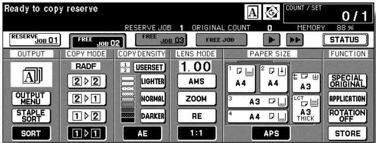
Repeat step 3 to 5. Up to 10 reserve jobs can be prepared.
Copying on the reserve job will start automatically after completing the warm-up.

HINTS
- To set the fourth reserve job, touch the arrow key on the far right in the Folder key area to display succeeding folder keys. See p. 3-35 ~ p. 3-37.
- To stop printing, press [STOP]. See p. 3-9 for details.
- The Job Status Screen allows you to alter the output order of the reserve jobs or to delete the reserve job. See p. 3-38 ~ p. 3-40.
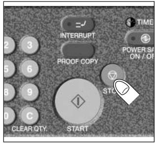
Follow the procedure below to stop scanning or printing.
- Touch to highlight SCAN JOB or PRINT JOB to be suspended.
- Press [STOP].
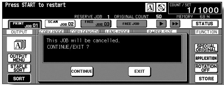
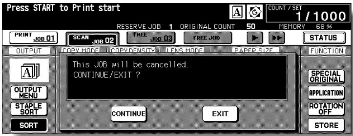
The current machine operation of the selected job will be suspended, and the popup menu will display on the Basic Screen to ask you to continue or cancel the job.
3. Touch EXIT to cancel the job and delete the data, or CONTINUE to complete the job.
To select an appropriate paper size for getting your desired copy result, use APS (Automatic Paper Selection), or select paper size manually on the touch screen, as required.
To Select Paper Size Automatically (APS)
APS detects the size of originals placed on the RADF or platen glass and automatically selects and feeds copy paper of the same size, or selects an appropriate size according to the magnification ratio selected.

HINTS
- See the table on the following page for the relation of original size, magnification ratio and copy paper size.
- The initial settings may have been altered by Key Operator. See p. 13-10 to p. 13-11.
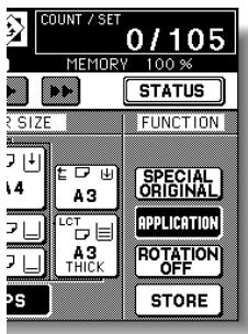
1. Touch to highlight APS at lower right corner of the Basic Screen.
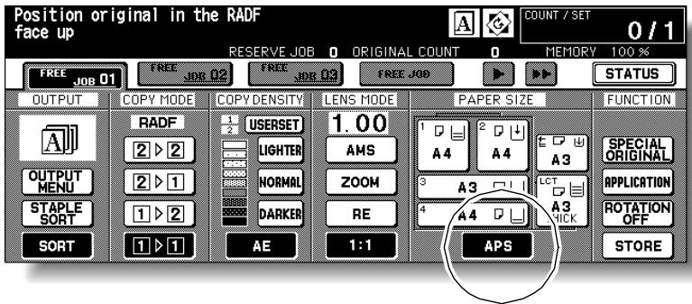
APS is already highlighted when the initial settings are restored.
2. Select additional copy conditions, as desired.
3. Enter the desired print quantity from the control panel keypad.

HINT
See p. 3-6 for details on setting print quantity.
4. Position original(s).

HINTS
- See p. 11-8 to p. 11-10 for paper sizes detectable from the RADF or on the platen glass.
- See p. 3-2 to p. 3-5 for details on positioning originals.
- Key Operator can deactivate APS when original is set in the RADF or on the platen glass. See p. 13-39 to p. 13-46.
5. Press [START].
Scanned image will be printed on the paper size automatically selected.
![KONICA MINOLTA 7255 - Press [START]. - 1](/content/2025/01/139764/images/5dfe447fabf1cc8ff1b84399b5421e66c2ec62eb3b6a66f20b3cd6f061d30157.jpg)
FOR DETAILS
- If the appropriate copy paper is not loaded in any tray, no copying will be performed, and a message will prompt you to load the appropriate paper.
- Copy result may not be satisfactory due to the Rotation function. In this case, set the function OFF manually. See. p. 7-5.
See the table below for the relation of original size, magnification ratio and copy paper size.
| Paper size | Original size | Paper size | |||||||||
| A3 | B4 | F4 | A4 | A4R | B5 | B5R | A5 | A5R | |||
| Magnification ratio | 0.25 - 0.42 | B6R | B6R | B6R | B6R | B6R | B6R | B6R | B6R | B6R | 0.25 - 0.42 |
| 0.43 - 0.50 | A5R | A5 | 0.43 - 0.50 | ||||||||
| 0.51 - 0.55 | B5R | A5R | A5 | 0.51 - 0.55 | |||||||
| 0.56 - 0.57 | A5R | 0.56 - 0.57 | |||||||||
| 0.58 - 0.61 | B5R | A5R | A5 | 0.58 - 0.61 | |||||||
| 0.62 - 0.64 | A4R | 0.62 - 0.64 | |||||||||
| 0.65 - 0.71 | B5R | 0.65 - 0.71 | |||||||||
| 0.72 - 0.78 | B4 | A4R | B5 | B5R | A5R | 0.72 - 0.78 | |||||
| 0.79 - 0.82 | A4R | 0.79 - 0.82 | |||||||||
| 0.83 - 0.86 | B4 | B5 | B5R | 0.83 - 0.86 | |||||||
| 0.87 - 0.90 | A3 | A4 | A4R | A5R | 0.87 - 0.90 | ||||||
| 0.91 - 1.00 | F4 | 0.91 - 1.00 | |||||||||
| 1.01 - 1.10 | A3 | B4 | A3 | B4 | A4 | A4R | B5 | B5R | 1.01 - 1.10 | ||
| 1.11 - 1.15 | A3 | A3 | B4 | 1.11 - 1.15 | |||||||
| 1.16 - 1.22 | 1.16 - 1.22 | ||||||||||
| 1.23 - 1.41 | A3 | A4 | A4R | A4R | 1.23 - 1.41 | ||||||
| 1.42 - 1.73 | A3 | A3 | B4 | 1.42 - 1.73 | |||||||
| 1.74 - 4.00 | A3 | 1.74 - 4.00 | |||||||||
To Specify Desired Paper Size (AMS)
When a paper size is specified on the touch screen, an appropriate reduction or enlargement ratio will be selected automatically according to the original size detected from the RADF or the platen glass.

HINTS
- See the table on the following page for the relation of original size, copy paper size, and magnification ratio automatically selected.
- Wide paper size can be specified when AMS is in use. In this case, the same magnification ratio as that of the standard size will be selected automatically.
-
If copying in 1.00 (100%) magnification mode with specifying a paper size is desired, see p. 3-14.
-
Touch a tray key on the Basic Screen to select the desired paper size.
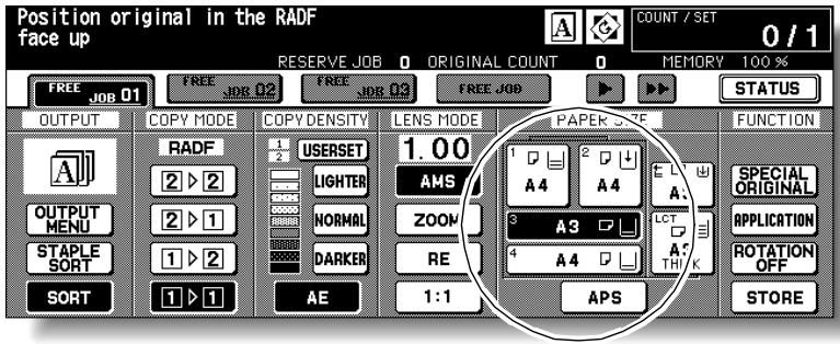
Selected tray key will be highlighted, and under the LENS MODE AMS indication will also be highlighted.
- Select additional copy conditions, as desired.
- Enter the desired print quantity from the control panel keypad.

HINT
See p. 3-6 for details on setting print quantity.
- Position original(s).

HINTS
- See p. 11-8 to p. 11-10 for paper sizes detectable from the RADF on the platen glass.
-
See p. 3-2 to p. 3-5 for details on positioning originals.
-
Press [START].
Scanned image will be printed on the specified paper size in the magnification ratio automatically selected.

FOR DETAILS
Copy result may not be satisfactory due to the Rotation function. In this case, set the function OFF manually. See. p. 7-5.
See the table below for the relation of original size, copy paper size, and magnification ratio automatically selected.
| Original size | ||||||||||
| A3 | B4 | F4 | A4 | A4R | B5 | B5R | A5 | A5R | ||
| Paper size | A3 | 1.00 | 1.15 | 1.27 | 1.00 | 1.41 | 1.15 | 1.63 | 1.41 | 2.00 |
| B4R | 0.86 | 1.00 | 1.10 | 0.86 | 1.22 | 1.00 | 1.41 | 1.22 | 1.73 | |
| A4 | 0.50 | 0.58 | 0.64 | 1.00 | 0.71 | 1.15 | 0.82 | 1.41 | 1.00 | |
| A4R | 0.71 | 0.82 | 0.90 | 0.71 | 1.00 | 0.82 | 1.15 | 1.00 | 1.41 | |
| B5 | 0.43 | 0.50 | 0.55 | 0.86 | 0.61 | 1.00 | 0.71 | 1.22 | 0.86 | |
| B5R | 0.61 | 0.71 | 0.78 | 0.61 | 0.86 | 0.71 | 1.00 | 0.86 | 1.22 | |
| A5 | 0.35 | 0.41 | 0.45 | 0.71 | 0.50 | 0.81 | 0.58 | 1.00 | 0.71 | |
| A5R | 0.50 | 0.58 | 0.64 | 0.50 | 0.71 | 0.58 | 0.81 | 0.71 | 1.00 | |
When the copier is turned ON, the magnification ratio is set to 1.00 (100%) automatically on the Basic Screen.
Follow each procedure described in this section to select the desired magnification ratio.
To Copy in 1.00 Magnification Mode
Follow this procedure to make a 100 % copy of the original image.
1. Close the RADF securely, then press [AUTO RESET].
![KONICA MINOLTA 7255 - Close the RADF securely, then press [AUTO RESET]. - 1](/content/2025/01/139764/images/5a9ada5b9d380c8746ef6f777bb2476669059b1edd80c7f10e1996d2d20e65b9.jpg)
The initial settings are restored. Check that APS is highlighted to indicate that the 1.00 magnification is selected.
![KONICA MINOLTA 7255 - Close the RADF securely, then press [AUTO RESET]. - 2](/content/2025/01/139764/images/34d60d85d6eabef13a874f1e0372b608707667cef65099d033eb187c38c6d178.jpg)
HINT
The initial settings may have been altered by Key Operator. See p. 13-10 to p. 13-11.
2. Select additional copy conditions, as desired.

FOR DETAILS
Specifying paper size will release 1.00 magnification and set AMS automatically. In this case, touch 1:1 to highlight it again.
3. Enter the desired print quantity from the control panel keypad.

HINT
See p. 3-6 for details on setting print quantity.
4. Position original(s).

HINT
See p. 3-2 to p. 3-5 for details on positioning originals.
5. Press [START].
To Copy in Fixed Magnification Mode (RE)
Use the 8 preset ratios (0.50, 0.71, 0.82, 0.86, 1.15, 1.22, 1.41, 2.00) and 3 user preset ratios to increase or decrease magnification in fixed amounts.
Specification for Fixed Magnification Mode <<
Incompatible Conditions: AMS, Repeat mode in Repeat, Reduce & Shift in Image Shift
1. Touch RE on the Basic Screen.
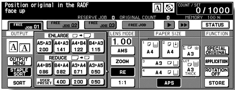
The popup menu for selecting the desired preset/user preset ratio will be displayed.

Please Be Reminded!
When starting a new copying job, be sure to close the RADF securely, then press [AUTO RESET].
2. Select the desired magnification.

FOR DETAILS
Touching any key on the popup menu will momentarily highlight that key, then the popup menu will disappear automatically.
The selected ratio will be displayed on the Basic Screen.
Three user preset ratios are adjustable by the Key Operator. See p. 13-14.
3. Select additional copy conditions, as desired.
4. Enter the desired print quantity from the control panel keypad.

HINT
See p. 3-6 for details on setting print quantity.
5. Position original(s).

HINT
See p. 3-2 to p. 3-5 for details on positioning originals.
6. Press [START].
To Copy in Zoom Mode
Use the Zoom mode to reduce or enlarge the copied original image in 1% increments.
Specification for Zoom Mode <<
Zoom range: 0.25 4.00
Incompatible Conditions: AMS, Repeat mode in Repeat, Reduce & Shift in Image Shift
1. Touch ZOOM on the Basic Screen.
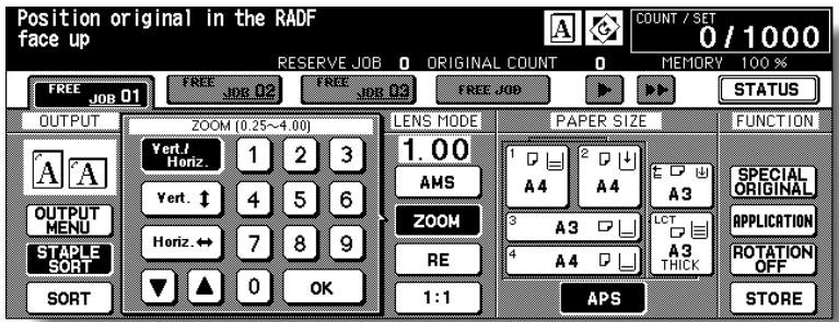
The popup menu for setting a zoom ratio will be displayed.

Please Be Reminded!
When starting a new copying job, be sure to close the RADF securely, then press [AUTO RESET].
2. Touch Vert./Horiz. on the popup menu, if not highlighted, then set the desired zoom ratio.

FOR DETAILS
Use the keypad on the popup menu to enter the desired magnification ratio in 3 digits, or use arrows ( / ) to scroll to the desired ratio.
If an incorrect ratio is entered, continue by entering the correct 3-digit ratio.
3. Touch OK.
The popup menu disappears automatically and the specified zoom ratio will be displayed on the Basic Screen.
4. Select additional copy conditions, as desired.
5. Enter the desired print quantity from the control panel keypad.

HINT
See p. 3-6 for details on setting print quantity.
6. Position original(s).

HINT
See p. 3-2 to p. 3-5 for details on positioning originals.
7. Press [START].
Automatic Exposure (AE) operates with the default settings. It detects the density of the original image and automatically selects the appropriate exposure for the copy.
![KONICA MINOLTA 7255 - Press [START]. - 1](/content/2025/01/139764/images/1d7a79f0d548e26c329044ef369ef68fcd8e04b0bcaa67acf0633a7506ec7790.jpg)
To Select Copy Density
Select manual copy density to adjust exposure (density) when originals are too light or too dark. Manual adjustments can be made in 9 levels on the Basic Screen.
- Touch DARKER to darken, or touch LIGHTER to lighten the copy image.
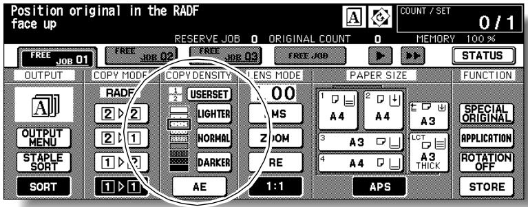
Highlight the desired exposure level indicator.

Please Be Reminded!
When starting a new copying job, be sure to close the RADF securely, then press [AUTO RESET].

FOR DETAILS
- Touch NORMAL to select the middle density level.
- To select the user-set density (USERSET1 or USERSET2), touch USERSET to highlight the desired indicator.
- When resuming AE, touch AE.
2. Select additional copy conditions, as desired.

HINT
See p. 13-12 to p. 13-13 to set the user-set density.
3. Enter the desired print quantity from the control panel keypad.

HINT
See p. 3-6 for details on setting print quantity.
4. Position original(s).

HINT
See p. 3-2 to p. 3-5 for details on positioning originals.
5. Press [START].
Density Shift
Use this function to shift each of nine density levels to three levels lighter or three levels darker.
This function can be set to use in combination with each of AUTO (Text/Photo), Text, Photo and Increase Contrast modes other than the general mode.
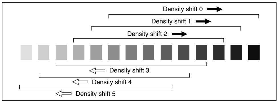
1. Touch SPECIAL ORIGINAL on the Basic Screen.
The Special Original popup menu will be displayed.
2. Select the desired mode.
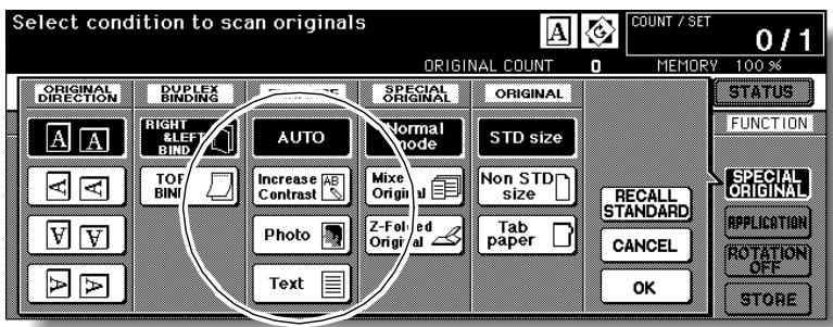
(eg.) To set the Text mode, touch Text to highlight it.
3. Press [P (COUNTER)].
The following message will be displayed.
Density Shift (Text)
2 (0 5)
4. Press any key (from 0 to 5) using the keypad to determine the Density shift.
Entering 6 or above will be ignored.
5. Touch OK on the Special Original popup menu.
Density shift in the selected enhance mode is determined.
The Basic Screen is initially set to 1-1 copy mode to make single-sided copies from single-sided originals.
Follow the procedure below to make double-sided copies from the originals scanned from the document feeder or from the platen glass.
Using RADF
Select the copy mode according to the original type (single-sided or double-sided).
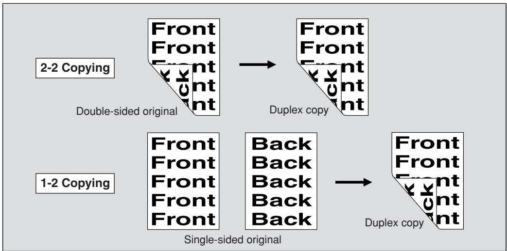
1. Touch 1-2 or 2-2 on the Basic Screen to highlight it.
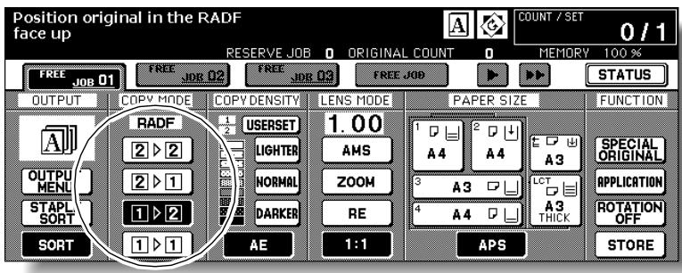

Please Be Reminded!
When starting a new copying job, be sure to close the RADF securely, then press [AUTO RESET].
2. Check and specify the original set direction and binding mode.
The Original direction icon is located at the upper left corner of the Basic Screen.
To change the original set direction, touch SPECIAL ORIGINAL on the Basic Screen to display the Special Original popup menu, then touch the desired original direction key to highlight it.

If double-sided originals are upside down on the reverse side and you want to make single-sided copies of the same direction, touch TOP BIND.
With this feature specified, next step is not needed. Proceed to step 4.
Touch OK to return to the Basic Screen.
3. Select the binding mode.
Touch OUTPUT MODE on the Basic Screen to display the Output Mode dropdown menu, then touch the desired binding mode key to highlight it.
Output Mode popup menu with Finisher
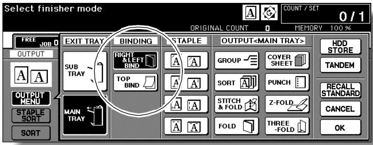
Output Mode popup menu without Finisher
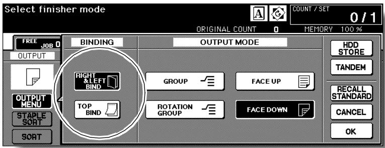

FOR DETAILS
Selecting TOP BIND will make copies upside down on the reverse side, while RIGHT&LEFT BIND copies normally.
Touch OK to return to the Basic Screen.
4. Select additional copy conditions, as desired.

FOR DETAILS
Some incompatible conditions may automatically release the selected copy mode. In this case, arrange all the settings to be compatible with the selected copy mode.
5. Enter the desired print quantity from the control panel keypad.

HINT
See p. 3-6 for details on setting print quantity.
6. Position originals FACE UP in the document feeder according to the original direction specified in step 2.

HINTS
- See p. 3-2 to p. 3-4 for details on positioning originals.
- Use RADF store mode (p. 3-33 to p. 3-34) when the original count exceeds 100.
7. Press [START].
The machine starts to scan originals, then to print duplex copies when ready for output.
Press [STOP] to suspend the scanning or printing job.
![KONICA MINOLTA 7255 - Press [START]. - 1](/content/2025/01/139764/images/5af1f0c59d88faedb0f3cbee1b7687adf356635e7a9550cb9a6423e4c59dc9af.jpg)
CAUTION
When the finisher / shift tray / paper exit tray capacity is exceeded due to the print quantity selected, remove the copied sets as they exit; otherwise, mishandled paper will occur.
Using Platen Glass
Use the platen glass to scan originals unsuitable for the document feeder.
Specification for Double-Sided Copying Using Platen Glass<<<
Use the Platen store mode.
See p. 11-8 for the information on unsuitable RADF originals.
□Incompatible Conditions: Face up exit using Secondary (sub) tray, Image Insert, OHP Interleave
1. Check and specify the original set direction and binding mode.
The Original direction icon is located at the upper left corner of the Basic Screen.
To change the original set direction, touch SPECIAL ORIGINAL on the Basic Screen to display the Special Original popup menu, then touch the desired original direction key to highlight it.
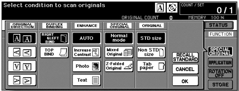
If the originals are upside down on the reverse side and you want to make copies of the same direction on both sides, touch TOP BIND.
With this feature specified, next step is not needed. Proceed to step 3.
Touch OK to return to the Basic Screen.
2. Select the binding mode.
Touch OUTPUT MODE on the Basic Screen to display the Output Mode dropdown menu, then touch the desired binding mode key to highlight it.
Output Mode popup menu with Finisher
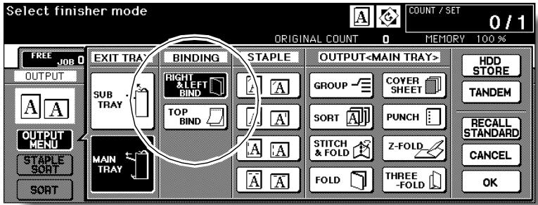
Output Mode popup menu without Finisher
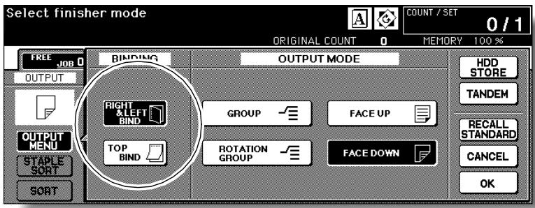

FOR DETAILS
Selecting TOP BIND will make copies upside down on the reverse side, while RIGHT&LEFT BIND copies normally.
Touch OK to return to the Basic Screen.
3. Position original FACE DOWN on the platen glass according to the original direction specified in step 1.
Be sure to start from the first page.

HINTS
- See p. 11-8 for paper sizes detectable on the platen glass.
See p. 3-5 for details on positioning originals. - Use Non-Image Area Erase to prevent the black copy mark to be produced when scanning the original with the document feeder open. See p. 9-29 to p. 9-30.
4. Touch 1-2 on the Basic Screen to highlight it.
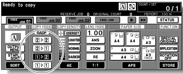
The STORE key will be automatically highlighted on the screen.

Please Be Reminded!
DO NOT press [AUTO RESET] at this point, otherwise the platen mode will be released to disable the copier from scanning the original placed on the platen glass.
5. Select additional copy conditions, as desired.

FOR DETAILS
Some incompatible conditions may automatically release the selected copy mode. In this case, arrange all the settings to be compatible with the selected copy mode.
6. Enter the desired print quantity from the control panel keypad.

HINT
See p. 3-6 for details on setting print quantity.
7. Press [START] to scan.
The front side image of the double-sided copy will be scanned into memory.
8. Replace the original on the platen glass with the back side image original, then press [START].
![KONICA MINOLTA 7255 - Replace the original on the platen glass with the back side image original, then press [START]. - 1](/content/2025/01/139764/images/df9895ddc1a96664e1d60bcf408f2d8e915ad58039e43d37835bd9915bd24180.jpg)
FOR DETAILS
Repeat this step until all originals are scanned.
Memory indicator on the upper right of the Basic Screen allows you to check the remaining memory.
To delete the scanned data without printing, press [STOP], then touch CANCEL on the popup menu to be sure the data is deleted.
9. Touch STORE to exit the Store mode.
STORE will return to the normal display.
10. Press [START] to print.
All the data in memory will be output.
Press [STOP] to suspend the printing job.
![KONICA MINOLTA 7255 - Press [START] to print. - 1](/content/2025/01/139764/images/ba0ecdce4e554e7663271f346e39accccdc49cc5ed9106f835f6a75321f9bbe6.jpg)
CAUTION
When the finisher / shift tray / paper exit tray capacity is exceeded due to the print quantity selected, remove the copied sets as they exit; otherwise, mishandled paper will occur.
Making Single-Sided Copy from Double-Sided Originals (2-1)
Use RADF and select 2-1 copy mode to make single-sided copies from double-sided originals.
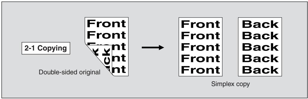
1. Touch 2-1 on the Basic Screen to highlight it.
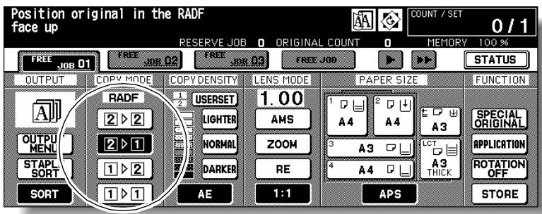

Please Be Reminded!
When starting a new copying job, be sure to close the RADF securely, then press [AUTO RESET].
2. Check and specify the original set direction and binding mode.
The Original direction icon is located at the upper left corner of the Basic Screen.
To change the original set direction, touch SPECIAL ORIGINAL on the Basic Screen to display the Special Original popup menu, then touch the desired original direction key to highlight it.
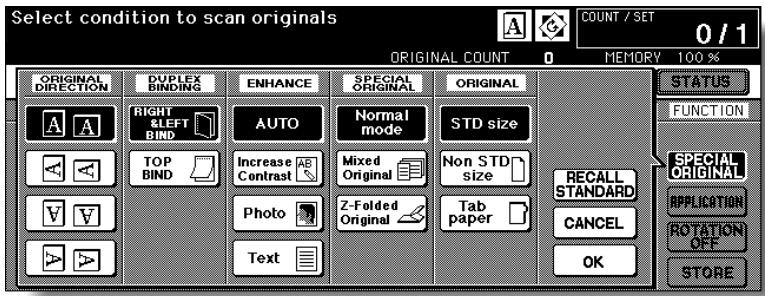
If double-sided originals are upside down on the reverse side and you want to make single-sided copies of the same direction, touch TOP BIND.
Touch OK to return to the Basic Screen.
3. Select additional copy conditions, as desired.

FOR DETAILS
Some incompatible conditions may automatically release the selected copy mode. In this case, arrange all the settings to be compatible with the selected copy mode.
4. Enter the desired print quantity from the control panel keypad.

HINT
See p. 3-6 for details on setting print quantity.
5. Position originals FACE UP in the document feeder according to the original direction specified in step 2.

HINTS
- See p. 3-2 to p. 3-4 for details on positioning originals.
- Use RADF store mode (p. 3-33 to p. 3-34) when the original count exceeds 100.
6. Press [START].
The machine starts to scan originals, then to print simplex copies when ready for output.
Press [STOP] to suspend the scanning or printing job.
![KONICA MINOLTA 7255 - Press [START]. - 1](/content/2025/01/139764/images/bb2e56a3d7a02785ab2fef56a3b33665ed03e6696d8717ca8a887edfe75521ba.jpg)
CAUTION
When the finisher / shift tray / paper exit tray capacity is exceeded due to the print quantity selected, remove the copied sets as they exit; otherwise, mishandled paper will occur.
Copying Using Special Paper (Multi-Sheet Bypass Tray)
Use the Multi-sheet bypass tray to copy using special (non-standard) paper. Specify the paper type and size to be loaded on the Multi-sheet bypass tray, as described below.

HINT
When loading special paper in the main body tray or in the LCT to use it on a regular basis, the paper type and size should be specified in the Key Operator setting. See p. 13-23 to p. 13-24.
1. Open the Multi-sheet bypass tray, and load the copy paper.

HINT
See p. 2-30 for further details.
2. Touch the Bypass key to highlight it.
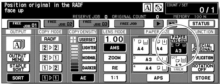
The PAPER TYPE/SIZE key will appear above the Bypass key. APS will be deselected, and AMS will be highlighted on the Basic Screen.
3. Touch PAPER TYPE/SIZE
The Paper Type/Size popup menu will be displayed.
4. Touch the desired paper type key.
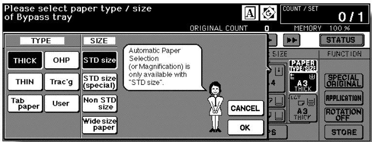
When THICK, THIN, Tab paper, OHP, Trac'g, or User is highlighted, a print job will conform to the selected paper type.
If no paper type indication is needed, touch the highlighted key to clear the selection in the TYPE area.
The selection will be reflected on the Basic Screen when restored.

FOR DETAILS
When Tab paper is selected, AMS is automatically selected. In this case, STD size (special) and Non STD size cannot be selected, and the loaded copy paper cannot be fed in 1-2 or 2-2 copying.
5. Specify the paper size.
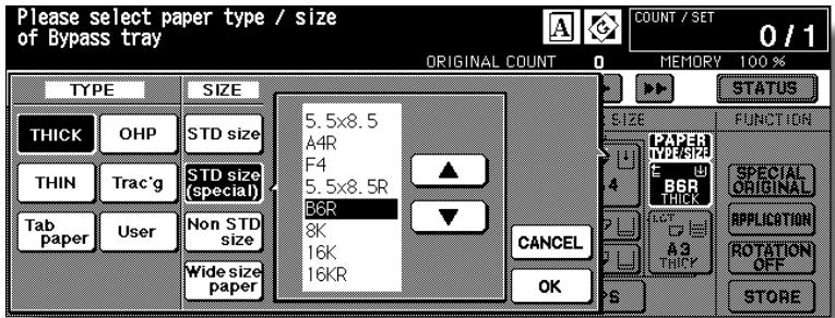
When STD size (special) is highlighted, the popup menu will appear. Use arrow keys to scroll to the desired size. In this case, both the paper size and type selected will be indicated on the Basic Screen.
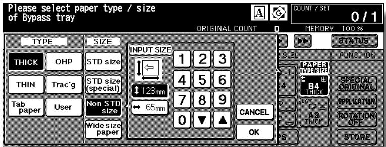
When Non STD size is highlighted, the popup menu will appear.
To set the vertical size, touch the vertical size key to highlight it, then use the keypad on the popup menu to enter the vertical size, or use arrows to scroll to that number.
To set the horizontal size, touch the horizontal size key to highlight it, then use the keypad on the popup menu to enter the horizontal size, or use arrows to scroll to that number.
In this case, the Special indication and paper type selected will be displayed on the Basic Screen, but the actual size information cannot be displayed.
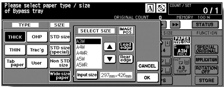
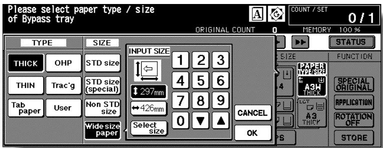
When Wide size paper is highlighted, the popup menu will appear.
Use arrow keys to scroll to the desired wide size, then specify the precise dimensions of paper to be used, following the procedure below.
(1) Touch Input size. The Input Size popup menu will appear.
(2) Touch the vertical size key to highlight it. Use the keypad on the popup menu to enter the vertical size, or use arrow keys to scroll to that number. The entered number should fall within the range from the vertical size of the standard size corresponding to the selected wide size, to a maximum of 314mm.
(3) Similarly, touch the horizontal size key to highlight it, then use the keypad on the popup menu to enter the horizontal size, or use arrow keys to scroll that number.
The entered number should fall within the range from the horizontal size of the standard size corresponding to the selected wide size, to a maximum of 459mm.
(4) Touch Select size to return to the Select Size popup menu.
Touch Lead edge or Rear edge to select the image starting position.
6. Touch OK to return to the Basic Screen.
7. Select additional copy conditions, as desired.

HINTS
- See p. 8-12 to p. 8-13 for details on copying non-standard size or tab paper originals.
See p. 9-17 to p. 9-18 for details on copying onto OHP films.
8. Enter the desired print quantity from the control panel keypad.

HINT
See p. 3-6 for details on setting print quantity.
9. Position original(s) FACE UP in the document feeder or FACE DOWN on the platen glass.

HINT
See p. 3-2 to p. 3-5 for details on positioning originals.
10. Press [START].
![KONICA MINOLTA 7255 - Press [START]. - 1](/content/2025/01/139764/images/770308dd5237543c39bf6af67eb8616eed864f115357edd2906165df0bcd968f.jpg)
FOR DETAILS
When using A5 thick paper for copying, move the conveyance lever as shown below.
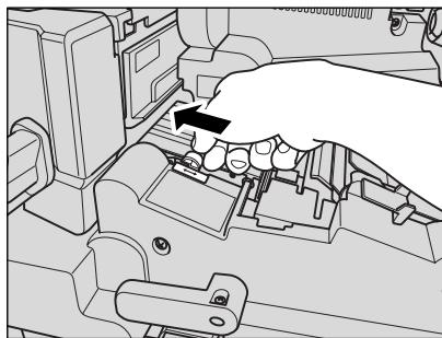
When completed, return the conveyance lever to its original position.
This section describes various copying features available on this machine using built-in memory.
To Scan Originals into Memory (Store Mode)
Store mode allows you to scan all the originals first, then to start continuous printing job.
Use RADF store mode for scanning large amount of originals.
Use Platen store mode for originals that cannot be fed through the document feeder due to thickness, size or condition.

FOR DETAILS
RADF tray capacity is 100; however, more than 100 originals can be scanned into memory using RADF store mode.
Specification for Store Mode<<<
Incompatible with RADF store mode: Image Insert, Dual Page, Storing image in Overlay Memory
Incompatible with Platen store mode: Storing image in Overlay Memory
1. Make copying selections, as desired.

Please Be Reminded!
When starting a new copying job, be sure to close the RADF securely, then press [AUTO RESET].
2. Touch STORE on the Basic Screen to highlight it.
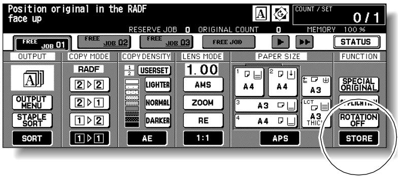
3. Enter the desired print quantity from the control panel keypad.

HINT
See p. 3-6 for details on setting print quantity.
4. Position original(s).
Using platen glass:
Place original FACE DOWN. Start scanning from the first page.

Please Be Reminded!
When Dual Page, Non-Image Area Erase, Auto detection mode of Repeat, or AUTO Layout is selected, keep the RADF open throughout the scanning procedure.
Using RADF:
Position originals FACE UP.
If the number of originals exceeds 100, divide them into blocks not exceeding 100 sheets and load them from the block with the first page.

HINT
See p. 3-2 to p. 3-5 for details on positioning originals.
5. Press [START] to scan.
![KONICA MINOLTA 7255 - Press [START] to scan. - 1](/content/2025/01/139764/images/cfd6a220f1841b8673e8557246c1fd67e6e2c2eaa7d9619a66547f8c7d2efea6.jpg)
FOR DETAILS
Repeat steps 4 and 5 until all originals are scanned.
Memory indicator on the upper right of the Basic Screen allows you to check the remaining memory.
To delete the scanned data without printing, press [STOP], then touch EXIT on the confirmation screen to be sure the data is deleted.

HINT
Should memory overflow occur frequently, it is recommended that you contact your Konica service representative to extend the memory capacity in your machine.
6. Touch STORE to exit the Store mode.
STORE will return to the normal display.
7. Press [START].
All the data in memory will be output.
Press [STOP] to suspend the printing job.
![KONICA MINOLTA 7255 - Press [START]. - 1](/content/2025/01/139764/images/4bea76c6ed7c87447b70c97c1ecc95f6e810c0aea1c989ee8d4b8afd9b0d9737.jpg)
CAUTION
When the finisher / shift tray / paper exit tray capacity is exceeded due to the print quantity selected, remove the copied sets as they exit; otherwise, mishandled paper will occur.
To Set Next Copying Job (Reserve)
The Reserve function allows you to set up a new job while a current (scan/ print) job is in process. When the current job is finished, the Reserve job starts printing immediately.
Specifications for Reserve<<
Job settings: Max. 10 (current job plus 9 reserve jobs)
□ When the current job is under Store mode, Image Insert, or Dual Page, the reserve job setting will be available after the copier starts to print the current job.
□ Incompatible Conditions: Interrupt copying, Scanning in Store mode, Proof copy, Storing image in Overlay Memory
1. Press [START] to start scanning/printing for the current job.
FREE JOB will become active to show that the reserve job setting is now available.
![KONICA MINOLTA 7255 - Press [START] to start scanning/printing for the current job. - 1](/content/2025/01/139764/images/f9681de71864a4feef0aab765794814d64375c2fe786a92956a52f556e434fa8.jpg)
2. Touch FREE JOB to highlight it.
The Reserve Job Setting Screen will be displayed.
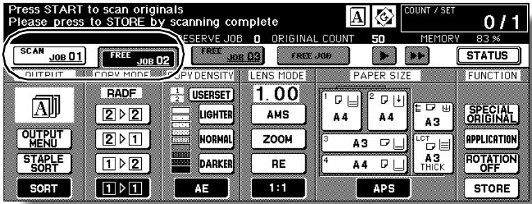
On the Reserve Job Setting Screen, all keys on the LCD and control panel will function for the reserve job.
3. Select copy conditions for the reserve job, as desired.

HINT
When trouble occurs while setting the reserve job, the PRINT or SCAN JOB key on the Basic Screen will change to JAM or ADD PAPER key. See p. 5-8 to p. 5-10.
4. Position original(s) after completing the scan for the current job.

HINT
See p. 3-2 to p. 3-5 for details on positioning originals.
5. Press [START] to start scanning for the reserve job.
![KONICA MINOLTA 7255 - Press [START] to start scanning for the reserve job. - 1](/content/2025/01/139764/images/19f2eff9df400b04f6210ce6203c412e002340bd5267dc99fa39f5682e8ec479.jpg)
![KONICA MINOLTA 7255 - Press [START] to start scanning for the reserve job. - 2](/content/2025/01/139764/images/ce9dd06a58b6e337acf661f79220e11d0cdd5a690ea9304ac5971980a5e76e22.jpg)
FOR DETAILS
When setting more than one reserve job, the next reserve job setting will be available after the copier starts to scan for the previous reserve job.
When setting the fourth copying job, touch the active FREE JOB key at the far right to scroll to the next reserve setting screen. Another three reserve job settings (04-06) will be available.
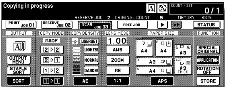
When setting the seventh copying job, touch the active FREE JOB key at the far right to scroll to the next reserve setting screen. Another four reserve job settings (07-10) will be available.
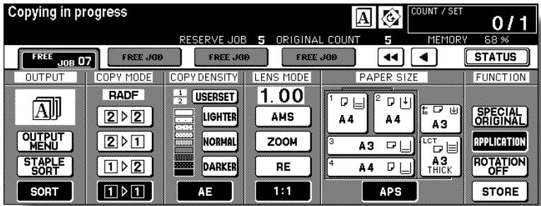
When completed, the Basic Screen for the current printing job will be restored.
To scroll to the next/previous screen, touch the arrow keys displayed at the right side of the folder keys.

HINT
When trouble occurs on a reserve job which is not currently displayed on the screen, the arrow key to scroll to that job will blink. See p. 5-8 to p. 5-10.
6. Copying of the reserve job will start automatically after completing the current job.

CAUTION
When the finisher / shift tray / paper exit tray capacity is exceeded due to the print quantity selected, remove the copied sets as they exit; otherwise, mishandled paper will occur.
To Check/Control Jobs in Progress (Job Status Screen)
The Job Status Screen allows you to perform the following functions.
- Confirm machine status
- Change order of reserve job
- Delete reserve job
View previous job list
View noncomplete job list - View tray information and machine status of the other machine in tandem mode.
1. Touch STATUS on the Basic Screen.
The Job Status Screen will be displayed.
Check the current status of the machine.
2. Perform the desired setting on the screen.
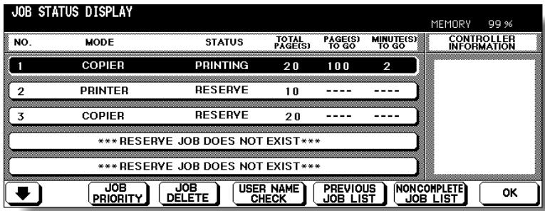

HINT
See the next page for details of the screen.
To change the order of reserve job:
Touch to highlight the desired reserve job key, then touch JOB PRIORITY.
The highlighted reserve job is advanced by one in printing order unless the job preceding the selected one is already in progress.
To clear reserve job:
Touch to highlight the desired reserve job key, then touch JOB CLEAR.
Touch YES to clear the highlighted reserve job, or NO to cancel.
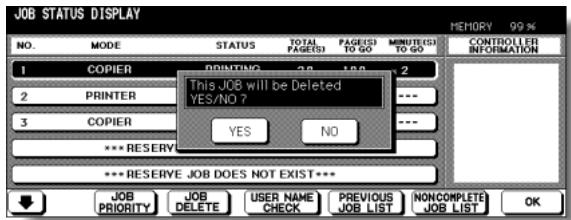
To check user name (not copier information):
Touch USER NAME CHECK to display the User Name Check Screen.
Check the user name indicated on the right side of the job number and operatio mode.
Touch OK to return to the Job Status Screen.
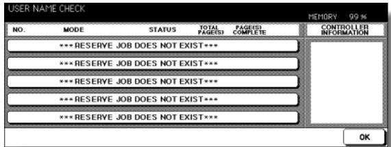
To display previous job list: Touch PREVIOUS JOB LIST to display the Previous Job List Screen.
Touch to scroll to the next page. Up to 16 previous jobs (4 pages) can be displayed. Touch
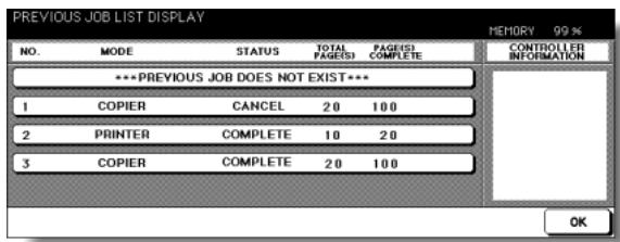
to return to the previous page.
Touch OK to return to the Job Status Screen.
To display noncomplete job list: Touch NONCOMPLETE JOB LIST to display the Noncomplete Job List Screen.
Touch to scroll to the next page. Up to 16 noncomplete jobs (4 pages) can be displayed.
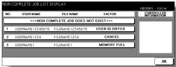
Touch to return to the previous page.
Touch OK to return to the Job Status Screen.
3. Touch OK on the Job Status Screen.
The Basic Screen will be restored.
Contents of Job Status Screen
NO.: Displays the No. (01-99) for each job assigned to the machine.
MODE: Displays the machine's current mode of operation. Three modes are listed below.
COPIER
PRINTER
SCANNER
STATUS: Displays the current status of the machine for each job.
READY :Ready to use in each mode
INTERRUPT : Interrupting the previous job
ERROR :Error in each mode
PRINTING : Printing in each mode
NO PAPER : No paper in copy/print mode
STOP : Stop in each mode
RESERVE :Ready to reserve
JAM : Jam in each mode
TOTAL PAGE(s): Displays the number of scanned pages for each job. (0 to 9999)
PAGE(s) LEFT: Displays the remaining copy count of the job.
0 to 9999 (The number exceeding 9999 will be displayed as 9999^ .)
Copy count
= No. of scanned pages x Print quantity
MINUTE(s) TO GO: Displays the time (in minutes) required for completing the job.
Exceeding 999 minutes: 999^
Shorter than 1 minute: < 1
Other: The following message will be displayed on the bar when the reserved job does not exist.
RESERVED JOB DOES NOT EXIST
TANDEM CONNECTED INFORMATION:
Displays the tray information and current status of the other machine when two copiers are connected and operate in tandem mode.
[Information]
Paper size loaded in each tray
Paper out indicator (when depleted in the tray)
Current status: OPERATING
STOP
PAPER SUPPLY
JAM
ERROR
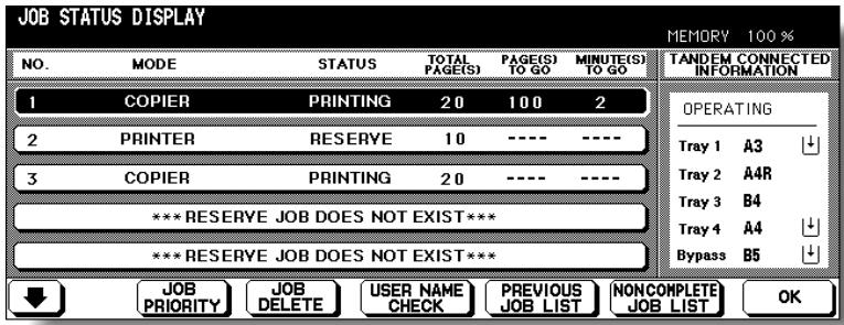
This section describes the output modes for a copier without the Finisher. The Non-sort mode is initially selected.
1 Non-sort mode copies the original set in amounts determined by the print quantity setting, then outputs sorted sets normally.
2 Rotation sort mode rotates every other sorted sets by 90^ upon exit, provided the same paper size is loaded in two trays, one tray with paper loaded in portrait orientation and the other tray with paper loaded in landscape orientation, e.g., A4 and A4R.
3 Group mode copies each original page in amounts determined by the print quantity setting, then outputs grouped sets normally.
4 Rotation group mode rotates every other grouped set by 90^ upon exit, provided the same paper size is loaded in two trays, one tray with paper loaded in portrait orientation and the other tray with paper loaded in landscape orientation, e.g., A4 and A4R.
Using Face Up mode in combination with the above four modes, simplex copies and odd numbered duplex copies exit face up on the exit tray.
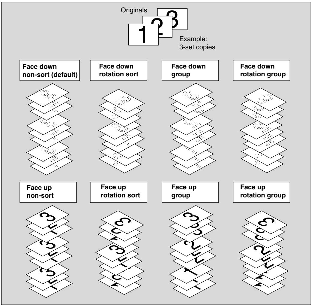
1. When using Rotation sort or Rotation group mode, load the same paper size into two trays in different orientation.

HINT
Non-sort mode is initially selected. Key Operator can change the initial output mode. See p. 13-10.
2. Select the desired output mode.
To select Non-sort mode:
Confirm that OUTPUT MENU and SORT are not highlighted on the Basic Screen.
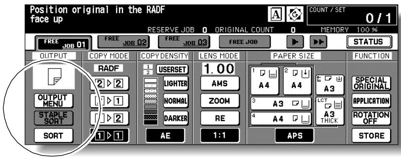
To select Rotation sort mode:
Confirm that OUTPUT MENU is not highlighted, then touch SORT to highlight it.
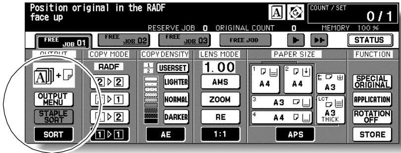
To select Group, Rotation group, or Face up mode:
(1) Touch OUTPUT MENU on the Basic Screen. The Output Mode popup menu will be displayed.
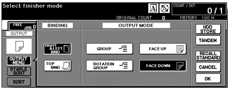
(2) Touch to highlight the desired mode key.
To use Face Up mode in combination, simply touch to highlight FACE UP instead of FACE DOWN.
(3) Touch OK.
The Basic Screen will be restored, with OUTPUT MENU highlighted.
- Select additional copy conditions, as desired.
- Enter the desired print quantity from the control panel keypad.

HINTS
-
See p. 11-3 to be sure that the exit tray capacity is not exceeded.
See p. 3-6 for details on setting print quantity. -
Position original(s) FACE UP in the document feeder or FACE DOWN on the platen glass.

HINT
See p. 3-2 to p. 3-5 for details on positioning originals.
- Press [START].
Press [STOP] to suspend the scanning or printing job.

CAUTION
When the paper exit tray capacity is exceeded due to the print quantity selected, remove the copied sets as they exit; otherwise, mishandled paper will occur.

FOR DETAILS: Output Icons on the Basic Screen
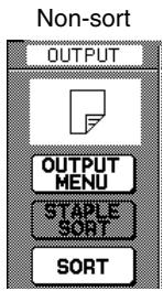
Face Down
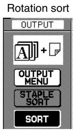
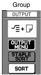
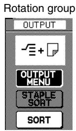
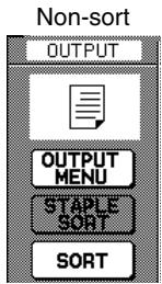
Face Up
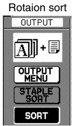
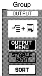
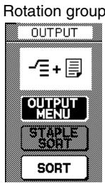
Finisher FS-110/111/210 is equipped with a primary (main) and a secondary (sub) exit trays. Without using any optional equipment, each exit tray provides the output modes as described below.
Primay (Main) Tray:
1 Non-sort mode simply means that the offset-stacker finisher modes are not selected. Copies will be stacked upon exit without being offset by sorted sets.
2 Sort mode outputs multiple copies of the original set, having each sorted set offset by 30mm upon exit.
3 Staple-sort mode offsets and staples each sorted set. Up to 50 sheets or within 5mm thick (FS-110/210) / 100 sheets or within 10mm thick (FS-111) can be stapled.
4 Group mode groups together multiple copies of each original and offsets the sets by 30mm upon exit.
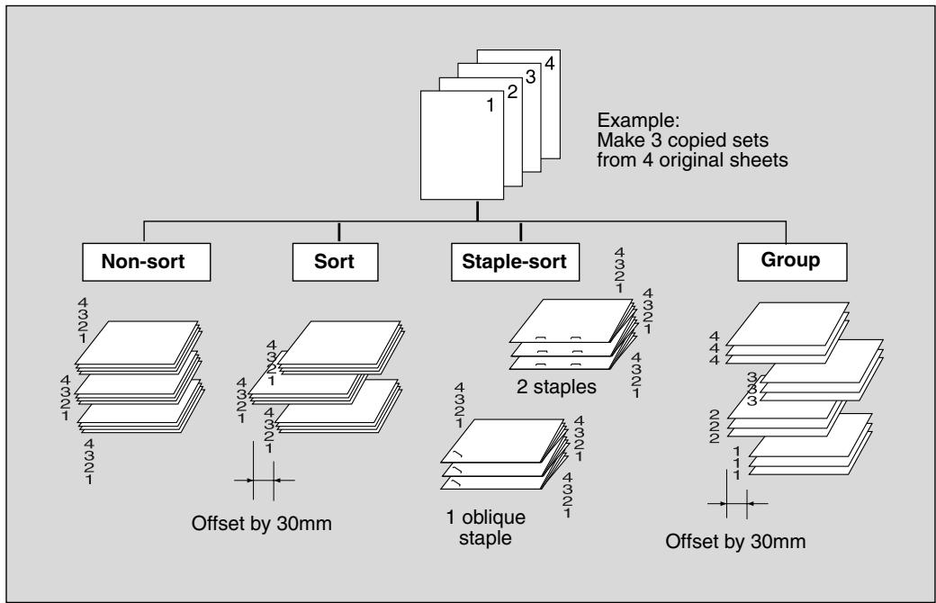
Secondary (Sub) Tray:
1 Face down non-sort exit outputs simplex copies and odd numbered duplex copies face down, without offsetting the sorted sets.
2 Face down group exit outputs multiple copies of each original face down, without offsetting the grouped sets upon exit.
3 Face up non-sort exit outputs simplex copies and odd numbered duplex copies face up, without offsetting the sorted sets.
4 Face up group exit outputs multiple copies of each original face up, without offsetting the grouped sets upon exit.
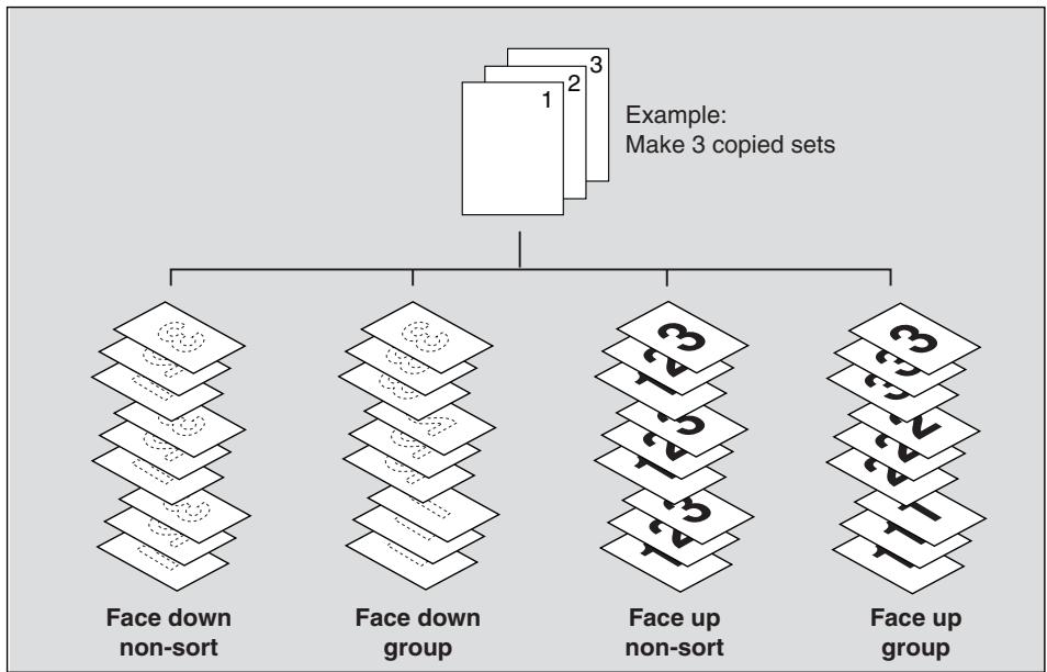
The copier is initially set to output to Primary (main) tray in Sort mode. Follow the procedure on the next page to change the output mode, as desired.

HINT
See Section 7 for the output modes using Finisher options.
>>>Specification for Output Modes with Finisher<<
Incompatible with Sort mode: Using platen glass (unless Image Insert, Dual Page, or Platen store mode is used), Fold, Stitch & Fold, Three-Fold, OHP Interleave
□ Incompatible with Staple-sort mode: Using platen glass (unless Image Insert, Dual Page, or Platen store mode is used), Fold, Stitch & Fold, Three-Fold, OHP Interleave

Please Be Reminded!
Using excessively curled paper or some types of thin paper in Staplesort mode may cause poor results in arrangement of the stapled sets.
□ Incompatible with Group mode: 1-2 or 2-2 mode using platen glass (unless Platen store mode is used), Proof Copy, Fold, Stitch & Fold, Three-Fold, Sheet/Cover Insertion, Chapter, Combination, Booklet, OHP Interleave, Image Insert, Repeat
□ Incompatible with Group using Secondary (sub) tray: 1-2 or 2-2 mode using platen glass (unless Platen store mode is used), Proof Copy, Fold, Stitch & Fold, Three-Fold, Punch, Cover sheet feeding, Sheet/Cover Insertion, Chapter, Combination, Booklet, OHP Interleave, Image Insert, Repeat
□ Incompatible with Face Up exit: 1-2 or 2-2 mode using platen glass, Fold, Stitch & Fold, Three-Fold, Punch, Cover sheet feeding
1. Close the RADF securely, then press [AUTO RESET].
![KONICA MINOLTA 7255 - Close the RADF securely, then press [AUTO RESET]. - 1](/content/2025/01/139764/images/65547c017c8a989d29e00062e992b489387d0f427c511022e470bc1ac640ea54.jpg)
HINT
The Sort mode using Primay (main) tray is initially selected.
Key Operator can change the initial output mode. See p. 13-10.
2. Select the desired output mode.
To set Non-sort or Sort mode using Primary (main) tray: proceed to the next step.
To set Staple-sort mode using Primary (main) tray: proceed to step 4.
To set Group mode using Primary (main) tray or output to Secondary (sub) tray: proceed to step 5.
3. To set Non-sort or Sort mode:
Check that SORT is already highlighted on the Basic Screen in initial condition. To select Non-sort mode, touch SORT to deselect it.
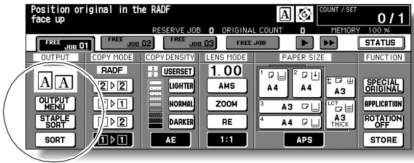
Proceed to step 6.
4. To set Staple-sort mode:
(1) Touch STAPLE SORT on the Basic Screen to highlight it.
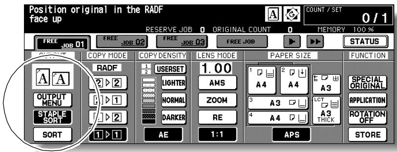
The staple position icon will be displayed in the output icon area.
(2) Touch OUTPUT MENU on the Basic Screen to display the Output Mode dropdown menu.
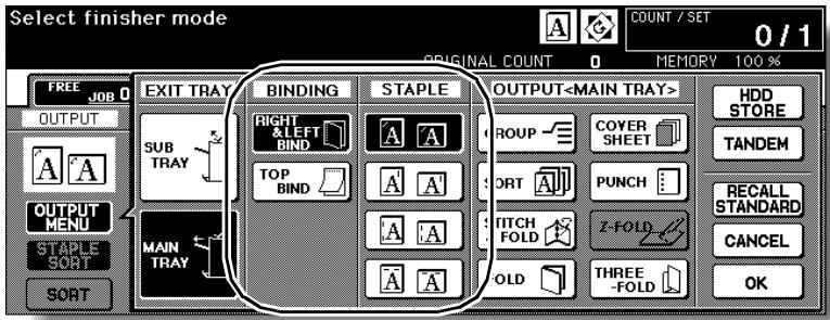
(3) Touch the desired staple position key, then touch OK.
The Basic Screen will be restored, with the selected staple position icon displayed.

FOR DETAILS
When making double-sided copies, select the desired binding mode on the Output Mode popup menu. See p. 3-53 for detail.
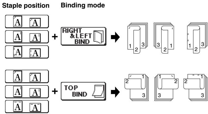
(4) Touch SPECIAL ORIGINAL on the Basic Screen to display the Special Original popup menu.
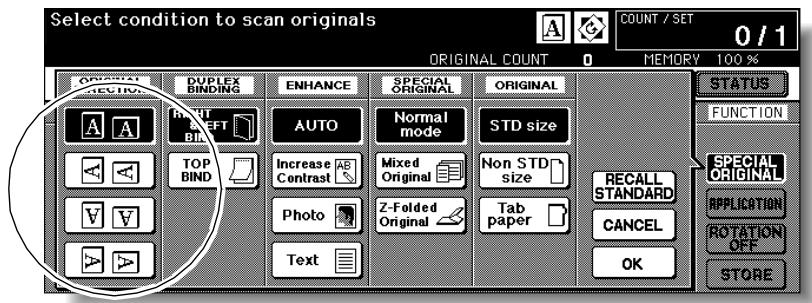
(5) Touch the desired original set direction key, then touch OK to return to the Basic Screen.
Proceed to step 6.
5. To set Group mode or output to Secondary (sub) tray:
Touch OUTPUT MENU on the Basic Screen to display the Output Mode popup menu.
Select the desired output mode.
To set the Group mode, touch GROUP to highlight it.
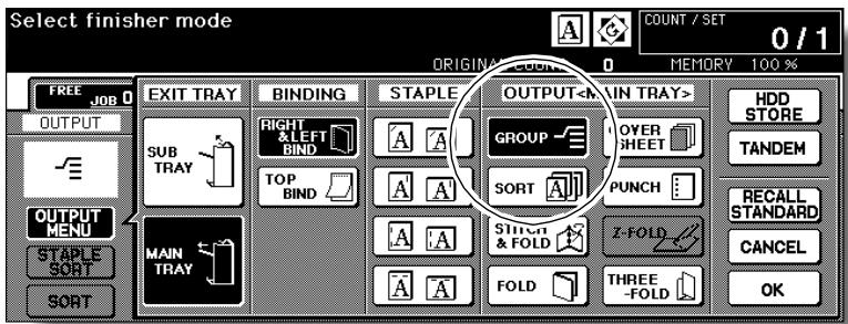
To set the output to Secondary (sub) tray, touch SUB TRAY to display the popup menu, then touch to highlight the desired key(s).
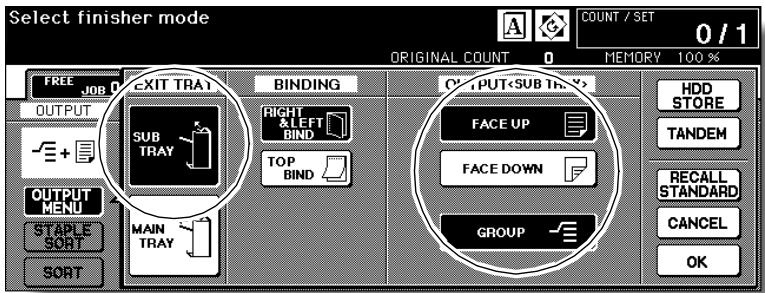
- Face down non-sort exit: FACE DOWN
- Face down group exit: FACE DOWN and GROUP
- Face up non-sort exit: FACE UP
- Face up group exit: FACE UP and GROUP
Touch OK to restore the Basic Screen. OUTPUT MENU will be highlighted, and the output icon of the selected output mode will be displayed in the output icon area.
- Select additional copy conditions, as desired.
- Enter the desired print quantity from the control panel keypad.

HINT
See p. 11-3 to be sure that the finisher capacity is not exceeded.
- Position original(s).

HINT
See p. 3-2 to p. 3-5 for details on positioning originals.
- Press [START].
Press [STOP] to suspend the scanning or printing job.

CAUTION
When the finisher exit tray capacity is exceeded due to the print quantity selected, remove the copied sets as they exit; otherwise, mishandled paper will occur.
This section describes output modes for a machine with Shift tray SF-101.
- Non-sort mode outputs multiple copies of the original set. Copies will be stacked upon exit without being offset by sorted sets.
- Sort mode outputs multiple copies of the original set, having each sorted set offset by 30mm upon exit.
- Group mode groups together multiple copies of each original and offsets the sets by 30 ~mm upon exit.
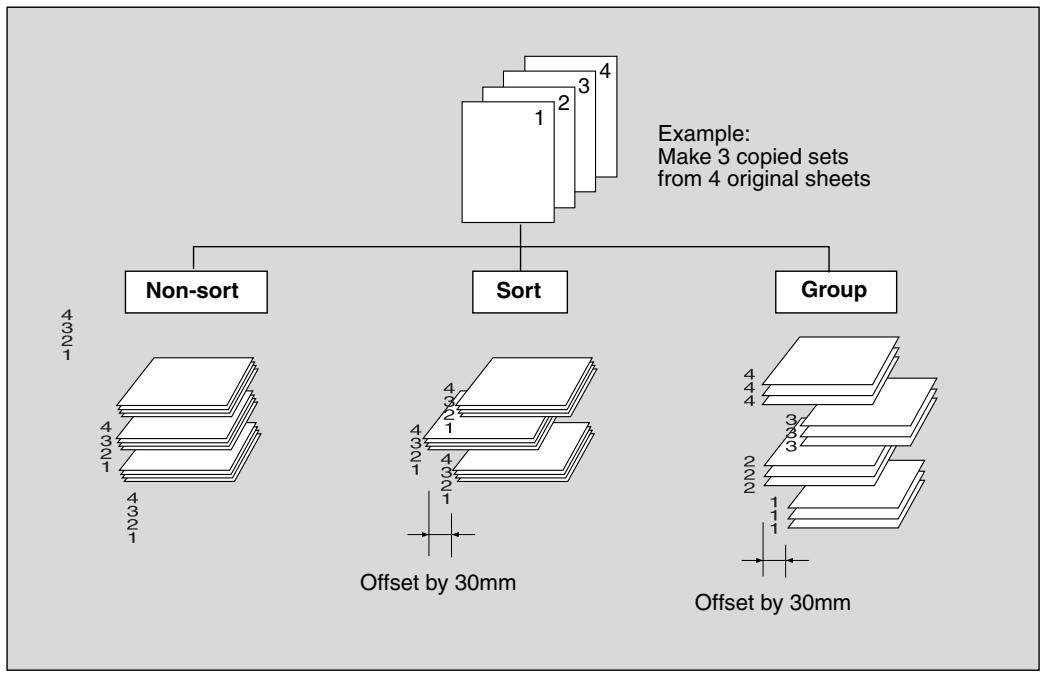
The copier is initially set to output in Sort mode.
Follow the procedure on the next page to change the output mode, as desired.
>>>Specification for Output Modes with Shift Tray<<
Incompatible with Sort mode: Using platen glass (unless Image Insert, Dual Page, or Platen store mode is used), OHP Interleave
□ Incompatible with Group mode: 1-2 or 2-2 mode using platen glass (unless Platen store mode is used), Proof Copy, Tandem Copying, Sheet/Cover Insertion, Chapter, Combination, Booklet, OHP Interleave, Image Insert, Repeat
1. Close the RADF securely, then press [AUTO RESET].
![KONICA MINOLTA 7255 - Close the RADF securely, then press [AUTO RESET]. - 1](/content/2025/01/139764/images/47d87e7c6b8bbba083ec098d0523ddd72d9339c94336bd2aa18d0f754a7cf1f9.jpg)
HINT
Key Operator can change the initial output mode. See p. 13-10.
2. Select the desired output mode.
To set Non-sort or Sort mode: proceed to the next step.
To set Group mode: proceed to step 4.
3. To set Non-sort or Sort mode:
Check that SORT is already highlighted on the Basic Screen in initial condition. To select Non-sort mode, touch SORT to deselect it.
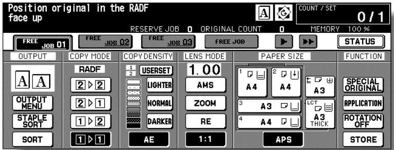
Proceed to step 5.
4. To set Group mode:
Touch OUTPUT MENU on the Basic Screen to display the Output Mode dropdown menu.
Select the desired output mode.
To set the Group mode, touch GROUP to highlight it
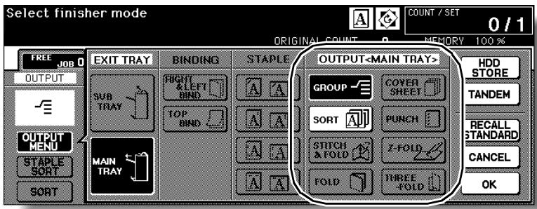
Touch OK to restore the Basic Screen. OUTPUT MENU will be highlighted.
5. Select additional copy conditions, as desired.
6. Enter the desired print quantity from the control panel keypad.

HINT
See p. 11-3 to be sure that the finisher capacity is not exceeded.
7. Position original(s).

HINT
See p. 3-2 to p. 3-5 for details on positioning originals.
8. Press [START].
Press [STOP] to suspend the scanning or printing job.
![KONICA MINOLTA 7255 - Press [START]. - 1](/content/2025/01/139764/images/a2acd1ba6adc43d60ca424e49a2272ef6936cb0d472ca4f13b5da026a7e53c63.jpg)
CAUTION
When the shift tray capacity is exceeded due to the print quantity selected, remove the copied sets as they exit; otherwise, mishandled paper will occur.
TIP: Output Icons on the Basic Screen
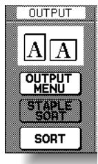
Non-sort
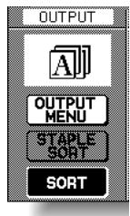
Sort
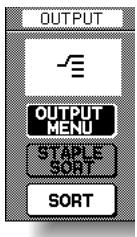
Group
When copying in 1-2 or 2-2 mode, specify the binding mode on the Output Mode popup menu to obtain the desired copy result.
Right & Left bind: Normal duplex copies
Top bind: Duplex copies arranged upside down on the reverse side

HINT
If the originals are upside down on the reverse side and you want to make copies of the same direction or both sides, specify the original binding mode on the Special Original popup menu. See p.8-4 for details.
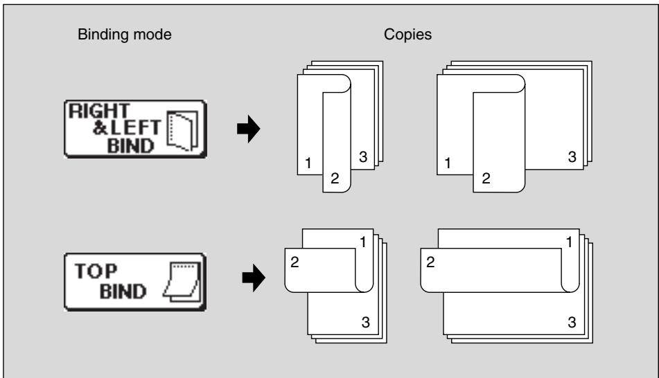
- Touch OUTPUT MENU to display the Output Mode popup menu.
- Touch to highlight the desired binding mode key.
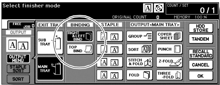
- Touch OK to return to the Basic Screen.
Follow the procedure below to copy with a previous job's settings.

FOR DETAILS
- Only the last-completed output job settings can be recalled as the previous job settings. Non-complete job or reserve job settings cannot be recalled, even if the setting operations have been made last.
- The previous job settings can be recalled, even after the machine power is turned off then on.
1. Press [JOB MEMORY] on the control panel.
The Job No. Selection Screen will be displayed.
2. Touch PRE-JOB RECALL.
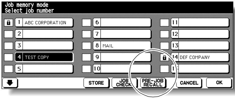
3. Touch OK to return to the Basic Screen.
4. Change the settings recalled on the screen, if desired.
5. When all settings are acceptable, position original(s) in the document feeder or on the platen glass, then press [START].
The settings of the previous output job is recalled on the screen.
Checking Feature Selections and Proof Copying
Use the Check mode to confirm copying selections before starting print operation.
In this mode, use Proof copy to produce a sample of the copied set before making multiple copies. This is a convenient and cost effective way of viewing the results of the following copying selections.
-
Copying conditions using Store mode
-
Booklet
-
Sheet/Cover insertion
-
Image insert
Chapter
- Dual page
Combination
- Program job
Specifications for Check Mode and Proof Copy<<
Proof copy is available when using RADF, or Platen store mode for multiple originals.
Proof copy cannot be used for testing the Userset density.
Proof copy is unavailable with Group output mode.
1. Select the desired copy conditions and enter the desired print quantity.

Please Be Reminded!
When starting a new copying job, be sure to close the RADF securely, then press [AUTO RESET].
2. Position original(s).

HINT
See p. 3-2 to p. 3-5 for details on positioning originals.
3. Press [CHECK] on the control panel.
![KONICA MINOLTA 7255 - Press [CHECK] on the control panel. - 1](/content/2025/01/139764/images/e5ff9f1314a51e6548cf9057551f05df7eae6e73a6b2406f066e1a5e091ff354.jpg)
The Check Screen will be displayed.
![KONICA MINOLTA 7255 - Press [CHECK] on the control panel. - 2](/content/2025/01/139764/images/f8a44973d149193408a660c8242a8a04c858037dab3c8eab288edf38ab9829bf.jpg)
Verify the settings made for the current job.
- When settings are OK, proceed to step 8.
- When a set of sample copy is needed, proceed to step 6.
- When making any setting change from the Check Screen, proceed to the next step.
- When releasing any setting from the Check Screen, proceed to step 5.
4. To change the settings:
Touch the desired copying condition key on the Check Screen to highlight it. Any key that cannot be highlighted indicates that the copying condition cannot be changed from the Check Screen.
Touch CHANGE SETTING.
The LCD will display an appropriate screen to change the copying condition selected.

FOR DETAILS
- Selecting a basic copying condition key will display the Basic Screen.
- Selecting Enhance Mode, Special Orig., or Original key will display the Special Original popup menu.
- Selecting an application function key will display the Change Application Selection Screen.
When BOOK MARK has been checked on a subsequent screen, selecting the application function key will jump to that screen. See p. 9-2 for details.
- CHANGE SETTING will not function for the following application functions, however they can be released by touching RELEASE SETTING: Non-Image Area Erase, Reverse Image, AUTO Layout, Full-Image Area, Overlay.
Change the setting as desired, then restore the Check Screen to return to the checking steps.
From the Basic Screen, press [CHECK] to return to the Check Screen.
From the Special Original popup menu or Change Application Selection Screen, touch OK to return to the Check Screen.
- When making a set or sample copy, proceed to step 6.
- To start printing without proofcopying, proceed to step 8.
5. To release the settings:
Touch the desired copying condition key on the Check Screen to highlight it, then touch RELEASE SETTING.
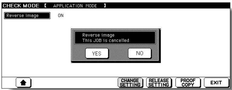
The confirmation screen will appear on the Check Screen.
Touch YES to cancel the function, or NO to restore.
- When making a set of sample copy, proceed to the next step.
To start printing without proofcopying, proceed to step 8.
6. Press [PROOF COPY] on the control panel or touch PROOF COPY on the Check Screen.
A set of sample copy will be output.
![KONICA MINOLTA 7255 - Press [PROOF COPY] on the control panel or touch PROOF COPY on the Check Screen. - 1](/content/2025/01/139764/images/610d6d9154f26cb199793ca258e7f928e88296cfb1cc60282124a9ec7028b8bd.jpg)
FOR DETAILS
- Press [STOP] to suspend the proof copying. In this case, the scanned image data will not be deleted from memory.
- As to the copying conditions indicated on the keys that appear dimmed after proof copying, you cannot change or release the selection.
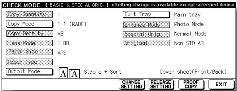
- When the copy result is satisfactory, proceed to the next step.
- When any setting change is required, return to step 4, then repeat proof copying, as required.
If the desired selection cannot be changed, press [STOP] to delete all the data in memory, then press [AUTO RESET] to restart the job setting.
7. Change the print quantity, as required.

FOR DETAILS
Proof copy can be performed as needed, until the print quantity amount on the Basic Screen reaches zero. (Note that the print quantity amount on the Check Screen does not change.)
If required, change the print quantity on the Basic Screen.
8. Press [START].
If the print quantity is not changed, the copier will output the rest, except the sample sets.
![KONICA MINOLTA 7255 - Press [START]. - 1](/content/2025/01/139764/images/c78852387d488ccc878050803fd785d9210538fd0f219a35c8fe2c54f131c8e6.jpg)
CAUTION
When the finisher / shift tray / paper exit tray capacity is exceeded due to the print quantity selected, remove the copied sets as they exit; otherwise, mishandled paper will occur.
Use the Interrupt mode to interrupt copying in progress to perform a simple job. When interrupt copying is completed, the settings for the initial job restore automatically and the Basic Screen displays.
Interrupt copying is available when the copier is performing the following operations:
- Continuously printing the image stored in memory
- Scanning the originals into memory
- Scanning the originals into memory while printing in Reserve mode

HINT
If desired, Key Operator can change the timing to stop current machine operation for interrupt copying.
Note that the compatible copying conditions vary according to the timing selected. See p. 13-39 to p. 13-46.
Specification for Interrupt Mode<<
The Interrupt mode cannot be selected with the following copier conditions: The Basic Screen is not displayed.
Overlay Memory is in use.
The Call for Service message displays or a paper misfeed occurs.
□Incompatible: Reserve, Storing image in Overlay Memory
1. Press [INTERRUPT] on the control panel.
The [INTERRUPT] LED turns on and all JOB indicators on the Basic Screen change to INTERRUPT.
![KONICA MINOLTA 7255 - Press [INTERRUPT] on the control panel. - 1](/content/2025/01/139764/images/64a5f84c403303d1ba3f5791915a378ce9c4bfb8ac9c492ec5a4de76e79345c6.jpg)
![KONICA MINOLTA 7255 - Press [INTERRUPT] on the control panel. - 2](/content/2025/01/139764/images/237f5bb216e7eddaddd8e562306a56c6862d893bf12c953d351ccd50675c294f.jpg)
HINT
The timing to enter the Interrupt mode varies according to the job in progress on the machine when [INTERRUPT] is pressed.
See the following page.

FOR DETAILS
In Reserve mode, pressing [INTERRUPT] before the copier finishes scanning the reserve job originals clears the settings selected for the reserve job.
For details of Reserve mode, see p. 3-35 to p. 3-36.
2. Set copy conditions, as desired.
The initial settings in Interrupt mode are as follows.
Copy Mode : 1-1
RADF : ON
AE : ON
Lens Mode : 1.00 (100%)
APS : ON
Print Quantity : 1
Finisher : Output to Secondary (Sub) tray

FOR DETAILS
Remove any document from the platen glass or from the document feeder, if present.
3. Position original(s).

HINT
See p. 3-2 to p. 3-5 for details on positioning originals.
4. Press [START] to start the interrupt copying.
![KONICA MINOLTA 7255 - Press [START] to start the interrupt copying. - 1](/content/2025/01/139764/images/55757c2d684c23b93985574c744ef9b6882ce6df07fe5125eb26535137491156.jpg)
FOR DETAILS
When [CHECK] is pressed during Interrupt copying, the information displayed reflects the initial copy job settings. Check mode will not display Interrupt copy job information.
5. When Interrupt copying is completed, press [INTERRUPT] again.
The [INTERRUPT] LED turns out and the INTERRUPT indicator on the Basic Screen returns to the JOB indicators.
The settings of the initial job will be restored on the Basic Screen.
6. Press [START] to resume copying.
![KONICA MINOLTA 7255 - Press [START] to resume copying. - 1](/content/2025/01/139764/images/46b1628427e8d349f05f12fa0708d5b6e7dc74aa0435ccff6189c2b1da68d054.jpg)
CAUTION
When the finisher / shift tray / paper exit tray capacity is exceeded due to the print quantity selected, remove the copied sets as they exit; otherwise, mishandled paper will occur.

FOR DETAILS
For particular jobs in progress, copying will cease only after certain phases of the immediate operation are completed, as indicated by the [INTERRUPT] LED conditions described below.
Collectively printing image stored in memory
The LED blinks until one set of the current job is printed.
Then the LED remains steady for the temporary job performed in Interrupt mode.
- Scanning originals into memory
The LED blinks until scanning is completed for all originals placed in the document feeder.
Then, the LED remains steady for the temporary job performed in Interrupt mode.
- Scanning originals into memory while printing in Reserve mode
The LED blinks until the copier completes the current printing job, scans all originals placed on the document feeder, and prints one set of the Reserved job.
The LED remains steady for the temporary job performed in Interrupt mode.
SECTION
4
Memory & Help Mode
How to Use Helpful Functions
Storing Job Conditions (Job Memory: Job Store) 4-2
Recalling Stored Job Settings (Job Memory: Job Recall) 4-5
Displaying Screen for Operation Guide (Help Mode) 4-6
A
Job Memory &Help Mode
Job Memory
Help Mode
Use Job Store to store up to 30 frequently used copy job settings, which can be recalled at any time. The stored jobs can be given alphabetical names.
Specifications for Job Memory<<
All copying functions can be selected.
Interrupt mode cannot be used while in Job Memory.
1. Make job selections from the Basic Screen and/or Application Selection Screen.

Please Be Reminded!
When starting a new copying job, be sure to close the RADF securely, then press [AUTO RESET].
2. Press [JOB MEMORY] on the control panel.
![KONICA MINOLTA 7255 - Press [JOB MEMORY] on the control panel. - 1](/content/2025/01/139764/images/1151639a862aa86bc90453c9095420833b77764283dd40d2d6c64483f6bbbe3a.jpg)
The Job No. Selection Screen will be displayed.
3. Touch STORE.
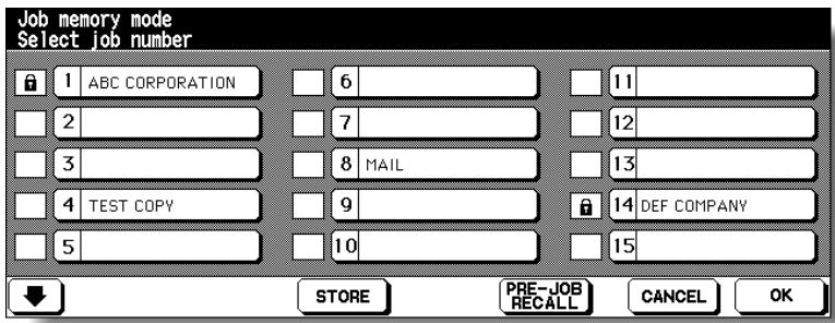
The Job Store Check Screen will be displayed.
4. Review the settings on the Job Store Check Screen.
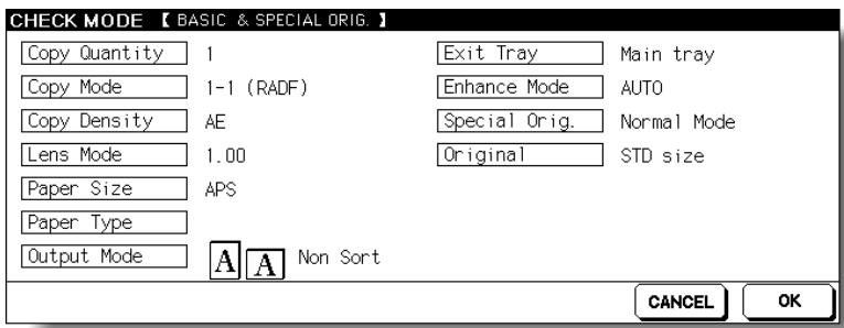
Check that the selections made in step 1 are correctly entered.

FOR DETAILS
If any correction is required, touch CANCEL to return to the Basic Screen. Make new selections, then restart the Job Store operation from step 2.
5. Touch OK.
The Job No. Selection Screen will be restored.

FOR DETAILS
To suspend the storing job after step 6, press [AUTO RESET]. Job Memory mode will be cancelled, and the Basic Screen will return from any screen.
6. Touch to highlight one of the keys numbered from 1~30 to store the job under that number.
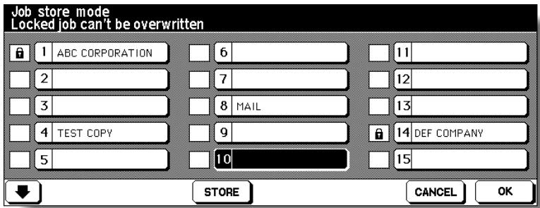
The screen displays 15 job number keys. The arrow key at the lower left corner can be used to scroll to the next/previous page.
A blank key indicates that no job is stored under that key, and a named job without a lock icon ( ⌒ ) displayed can be overwritten.
The key with a lock icon ( ) displayed is locked and cannot be selected.

HINT
To lock or unlock a job, and to delete a locked job, see p. 13-22.

Job Memory
Help Mode

FOR DETAILS
If you wish to cancel the job number selection, touch CANCEL to restore the Basic Screen, which displays the settings made in step 1. If you wish to cancel the settings, press [AUTO RESET].
7. Touch OK.
The Job Name Registration Screen will be displayed.
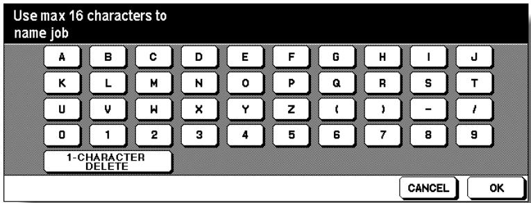
8. Enter a job name.
Enter a job name in up to 16 characters, using the touch screen alphabet keypad.
To correct an entry, touch 1-CHARACTER DELETE repeatedly to delete each character entered, then enter the correct job name.

FOR DETAILS
If you do not wish to enter a name, simply touch OK. The key displays 16 asterisks (*) in place of a name.
When changing the name of a job previously stored, touch 1-CHARACTER DELETE repeatedly to delete the previous name, then enter the new name.
9. Touch OK.
The Job No. Selection Screen will be restored.
Check that the job name has been correctly entered.
10. Touch OK to complete the setting and return to the Basic Screen.
Use Job Recall to recall jobs that are already stored in Job Memory.
1. Press [JOB MEMORY] on the control panel.
The Job No. Selection Screen will be displayed.
2. Touch to highlight a job number key to select a job you want to recall.
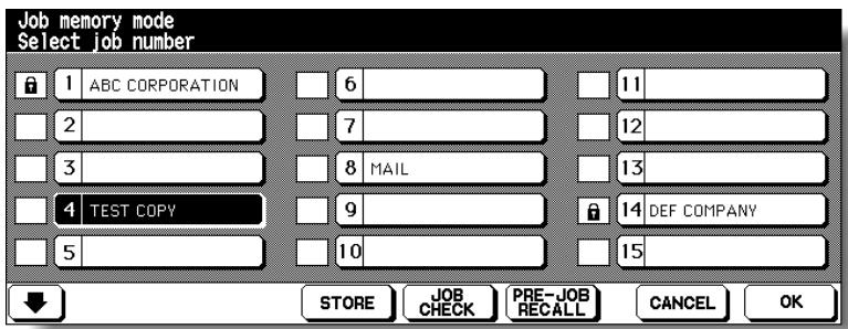
The screen displays 15 job number keys. If required, scroll to the next page with the arrow key to reach the desired job number key (16~30).
3. If desired, touch JOB CHECK.
The Job Recall Check Screen displays to enable you to review the settings.
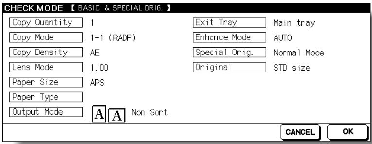
4. Touch OK.
The settings of the selected job will be recalled on the restored Basic Screen. To cancel the recall mode, touch CANCEL to return to the Basic Screen.
5. Position original(s), then press [START] to print.
Displaying Screen for Operation Guide (Help Mode)
The Help Screen provides you with the information about the current screen mode and about setting procedures. Help mode can be accessed from any screen except Job Memory and Key Operator Screens.
Help mode provides two types of Help Screen according to the current screen mode:
q Help Screen accessed from Basic Screen
w Help Screen accessed from screens other than Basic Screen
To Display Help Screen from Basic Screen
1. Return to the Basic Screen, then press [HELP].
![KONICA MINOLTA 7255 - Return to the Basic Screen, then press [HELP]. - 1](/content/2025/01/139764/images/62f8e65b06557ad45038d0a661b9a2d26f8ee7e77ac4a49bcbbe783eac68ca96.jpg)
The Help Screen will be displayed.
2. Touch the desired key to display specific information.

STAPLE SUPPLY provides information on replacing staple cartridge.
- PUNCH provides information on emptying trash basket.
- RADF provides information on positioning originals in the document feeder.
- TONER SUPPLY provides information on adding toner.
- PAPER SUPPLY provides information on loading paper in each tray.
- HELP MENU displays the Help Menu Screen which provides a list of all of the copier functions. When a function item is touched, the Help Screen displays information specific to that topic.

HINT
See the following page for details of the Help Menu Screen.
- PANEL CONTRAST displays the screen to adjust the contrast of the LCD panel.
- WEEKLY TIMER provides the current setting information of Weekly Timer. This key appears when the Weekly Timer function is turned ON.
FOR ASSISTANCE displays the extension number of the Key Operator. - TELEPHONE/FAX displays the phone/fax number of your service centre.

FOR DETAILS
- Touch on the Help Screen, if provided, to scroll to the next page.
Touch to return to the previous page. - Touch KEY OPERATOR MODE to enter the Key Operator mode. See p. 13-2.
3. Touch EXIT to return to the Basic Screen.

FOR DETAILS: Help Menu Screen
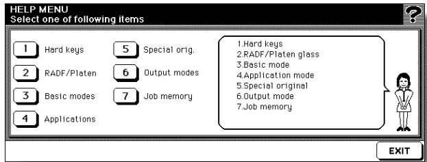
Select one of the 7 help menu items on the Help Menu Screen to display subsequent Help Screens.
Touch on the Help Screen, if provided, to scroll to the next page. Touch to return to the previous page.
Touch MENU on the subsequent Help Screen to return to the Help Menu Screen, then touch EXIT to restore the Basic Screen.
- "1. Hard keys" displays the information on control panel buttons.
- “2. RADF/Platen” displays the information on unsuitable RADF originals and maintenance of the document feeder and platen glass.
- "3. Basic modes" displays the information on basic functions provided on the Basic Screen.
- "4. Applications" displays operational information on 16 application functions provided on the Application Selection Screen.
- "5. Special orig." displays the information on functions provided on the Special Original popup menu.
- “6. Output modes” displays the information on Finisher functions.
- "7. Job memory" displays the information on Job Memory.
To Display Help Screen from Other Screens
1. While in any screen other than the Basic Screen, press [HELP].
![KONICA MINOLTA 7255 - While in any screen other than the Basic Screen, press [HELP]. - 1](/content/2025/01/139764/images/116313cd6f4a3b7c337df5c7c0c0f2a818ebc6aabba272888197b63f6a045768.jpg)
The Help Screen displays to provide the information about the current screen mode and setting procedures.
2. Touch EXIT.
The screen that was displayed before pressing [HELP] will be restored.
SECTION
5
Troubleshooting
How to Handle Machine Troubles
When "Call for Service" Message Is Displayed 5-2
Preventive Maintenance 5-4
Clearing Mishandled Paper 5-6
When "JAM" Appears on Folder Key (Or Arrow Key Flashes) ....5-8
When "ADD PAPER" Appears on Folder Key (Or Arrow Key Flashes)5-10
When “Memory Full” Message Is Displayed (Memory Overflow) ...5-11
When Power OFF/ON Screen Is Displayed. 5-13
Troubleshooting Tips 5-14
When “Call for Service” Message Is Displayed
A "Call for Service" message indicates a machine condition that requires the attention of your service representative.
The Call for Service Screen usually displays the telephone and facsimile numbers of your service representative.
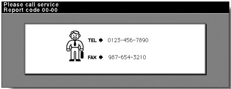

CAUTION
When the Call for Service Screen is displayed, be sure to contact your service representative immediately by following the procedure below.
1. Make note of the Report code No. indicated in the second line of the message area.

HINT
In the event the machine with the Remote Diagnostics option is automatically monitored by your service representative, the Key Operator can call for service using the Key Operator setting. See p. 13-48.

Please Be Reminded!
After calling for service using the Key Operator setting, be sure to turn OFF the sub power switch and main power switch immediately, then unplug the machine as described here.
2. Turn OFF the sub power switch and main power switch.
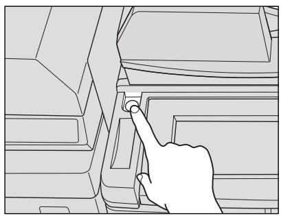
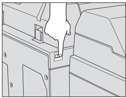
- Unplug the machine.
- Contact your service representative and report the condition and code No.
Limited Use of the Copier in Trouble
If the message shown below is displayed on the Call for Service Screen, you may continue operating the copier on a limited function basis and utilize the trays and ADU that are not affected by the trouble. To obtain this limited functionality of the copier, consult your service representative. Be sure to utilize the limited function only temporarily, and arrange for machine repair immediately.
- If the limited use of the copier is available, the following message is displayed in the message area instead of the Report code.
ex. Tray 2 failure Press AUTO to select except this tray
- Press [AUTO RESET].
Please switch ON/OFF E 18-2
Make note of the Report code No.
- Turn OFF then ON the power switch.
A copying job can be continued without using the troubled portion of the machine (ex. Tray 2).
CAUTION
EVEN IF THE COOPYING JOB CAN BE CONTINUED WITH THE ABOVE OPERATION, BE SURE TO CONTACT YOUR SERVICE REPRESENTATIVE IMMEDIATELY WHEN THE CALL FOR SERVICE SCREEN IS DISPLAYED.
After a set number of copies have been made on your copier, Preventive Maintenance (PM) will be required for maintaining optimal performance.
When preventive maintenance is due, a message and an icon (PMCALL) will prompt you to contact your service representative for maintenance.
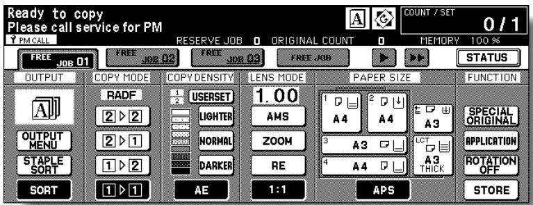
To Check the PM Counter
Follow the procedure below to check the PM counter to estimate the time when Preventive Maintenance is due.
- Press [P (COUNTER)] on the control panel.
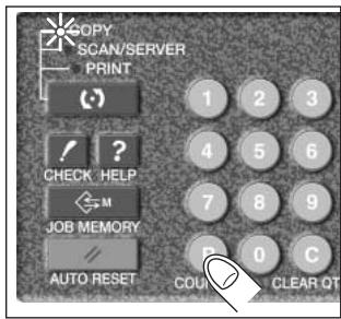
The Counter List Screen will be displayed.
- Press [CHECK].
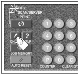
The PM counter will appear under the Printer counter on the screen.
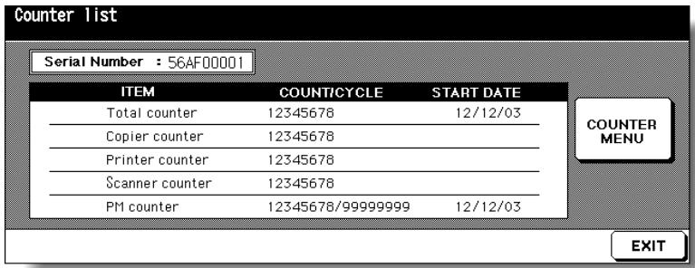

HINT
To print the Counter list including the PM counter, see p. 12-19.
3. Touch EXIT.
The Basic Screen will be restored.
When a paper misfeed occurs, the copier stops making copies and mishandled paper codes display on the screen to indicate misfeed area(s). Copying operation cannot be continued until all the misfeed locations are cleared.
Graphic Illustration key
Touch to display the subsequent screens for the disposal action.
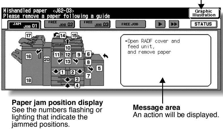

FOR DETAILS
The above screen displays all the jam numbers for the sake of explanation. Actually a few numbers appear when a paper misfeed occurs.
1. Touch Graphic Illustration on the screen.
The screen illustrating the method for the disposal action will be displayed.

Please Be Reminded!
Before performing the clearing procedure, see p. 1-2 for the caution label locations inside the machine.
2. Follow the procedure on the screen to remove misfed paper.
Touch on the screen, if provided, to go to the next page of a series of illustrations.

Please Be Reminded!
When removing mishandled paper, be sure to leave no torn paper inside the machine.
3. When completed, the Basic Screen will be restored.
If any misfeed location is left, the screen displays the next disposal procedure in the message area and the location number in the jam position display. Repeat steps 1 to 2 until all the locations are cleared.

WARNING
The drum unit generates high voltage.
To avoid bodily electrical shock, NEVER TOUCH the area.

CAUTION
The internal fixing unit is very hot.
To avoid getting burned, DO NOT TOUCH.

CAUTION
Be careful of removing staples stuck inside the machine so as not to get injured.

CAUTION
DO NOT INSERT your finger into the two RADF hinge portions, otherwise you may be injured.
When “JAM” Appears on Folder Key (Or Arrow Key Flashes)
If a misfeed occurs with the print/scan job in progress while you are setting a reserve job, SCAN or PRINT JOB folder key on the Basic Screen will change to flashing JAM JOB.
When more than four jobs have been specified and the folder key of the print/scan job in trouble is not currently displayed on the screen, the arrow key to scroll to that job will flash.
Follow the procedure below to remove mishandled paper.
1. Display the Jam Position Screen.
Touch JAM JOB. The Jam Position Screen will be displayd.
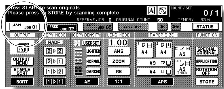
When the arrow key flashes, touch the key to scroll to the JAM JOB folder key, then touch it to display the Jam Position Screen.
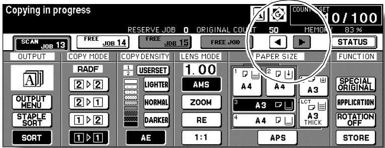

HINT
If ADD PAPER is displayed instead of JAM JOB, see p. 5-10.
2. Touch Graphic Illustration.
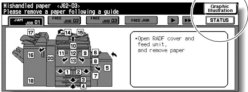
The screen illustrating the method for the disposal action will be displayed.

HINT
See p. 5-6 to p. 5-7 for details on clearing procedure.
3. Follow the procedure on the screen to remove misfed paper.
When all procedures are completed, the Basic Screen will be restored.

FOR DETAILS
JAM JOB has changed to STOP, and the settings for the current printing job are displayed on the screen.
4. Press [START].
The scan/print job will resume.
5. Touch FREE JOB to continue the reserve job setting.

WARNING
The drum unit generates high voltage. To avoid bodily electrical shock, NEVER TOUCH the area.

CAUTION
The internal fixing unit is very hot. To avoid getting burned, DO NOT TOUCH.

CAUTION
Be careful of removing staples stuck inside the machine so as not to get injured.

CAUTION
DO NOT INSERT your finger into the two RADF hinge portions, otherwise you may be injured.
When “ADD PAPER” Appears on Folder Key (Or Arrow Key Flashes)
If the paper supply for a print job in progress becomes depleted while you are setting a reserve job, PRINT JOB on the Basic Screen will change to flashing ADD PAPER.
When more than four jobs have been specified and the folder key of the print job in trouble is not currently displayed on the screen, the arrow key to scroll to that job will flash.
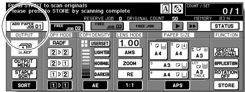
Follow the procedure below to continue the copying operation.
1. Display the Basic Screen for the print job in progress.
Touch ADD PAPER. The Basic Screen for the print job will be displayed.
When the arrow key flashes, touch the key to scroll to the ADD PAPER folder key, then touch it to display the Basic Screen for the print job.
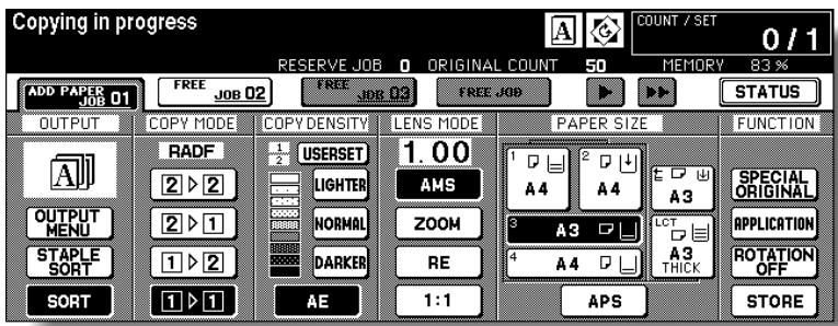
2. Check the flashing tray key, then supply that empty tray with copy paper.
When paper supply is completed, ADD PAPER changes to STOP.

HINT
See p. 2-24 to p. 2-33 for details on loading paper.
3. Press [START].
The print job will resume.
4. Touch FREE JOB to continue the reserve job setting.
When “Memory Full” Message Is Displayed (Memory Overflow)
In certain modes, this printer/copier uses memory to make operations convenient and smooth flowing. Occasional memory overflow may occur if the installed memory is inadequate for the copy conditions selected.
To handle the Memory overflow condition while in a job, take the appropriate action described below. These actions enable you to continue the job or suspend the job.

FOR DETAILS
Should memory overflow occur frequently, it is recommended that you contact your service representative to extend the memory capacity in your machine.
Memory Overflow in Current Job
When memory overflow occurs while scanning the first job, the machine stops immediately, and the screen provides JOB STOP and SCAN STOP as the only two available options.
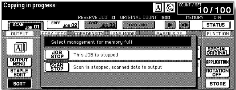

FOR DETAILS
If the job settings include Booklet mode, SCAN STOP will disappear.
- To delete all the scanned data and discontinue the job, touch JOB STOP.
- To give up further scanning but print out all the data already scanned into memory, touch SCAN STOP.
Memory Overflow in Reserve Job
When memory overflow occurs during the reserve operation, CONTINUE also appears on the active screen. In this case, the machine will not stop until all the jobs on standby for printing are completed.
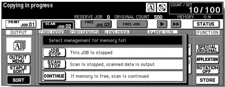

FOR DETAILS
If the job settings include Booklet mode, SCAN STOP will disappear.
- To delete the scanned data and discontinue the last reserve job, touch JOB STOP.
- To give up further scanning but print out the data already scanned for the last reserve job, touch SCAN STOP.
- To continue scanning the last reserve job, touch CONTINUE as the current printing job gradually enables memory for new data.
When Power OFF/ON Screen Is Displayed
When any trouble affects the electric signal of the copier, the Power OFF/ON Screen will be displayed.
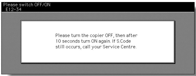
Follow the procedure below to turn the machine power off then on.
- Turn OFF the sub power switch.
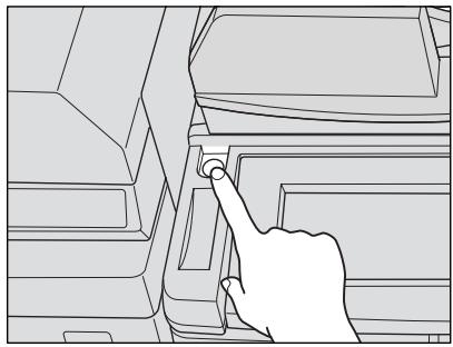
The main power switch is not required to be turned off.
- Wait about 10 seconds.
- Turn ON the sub power switch.
COPIER DOES NOT OPERATE WHEN POWER SWITCH IS ON
Fully insert paper trays.
Close RADF.
Close Front doors of main body.
Close Finisher door.
Check to be sure main power switch is ON.
Check to be sure power plug is firmly inserted in electrical socket.
COPY IMAGE IS TOO LIGHT
Manually adjust copy density to darker density.
Check toner indicator and add toner, if required.
Check paper for dampness. Do not leave paper in copier when humidity is high.
Check to see if Photo, Text, or Increase Contrast mode is required.
Check the Density shift.
COPY IMAGE IS TOO DARK
Manually adjust copy density to lighter density.
Check to see if Photo, Text, or Increase Contrast mode is required.
Check the Density shift.
COPY IMAGE IS NOT CLEAN OR SHOWS SPOTS
Use clean originals since dirt marks may be copied.
Keep platen glass and inner surface of document cover clean.
Call for service if "Call for service" is displayed in the message area.
Check density indicator and lighten if required.
COPY PAPER MISHANGLES DURING COPYING
Fan copy paper and load it with curl side in proper location. Do not exceed the tray capacity.
COPY IMAGE CAN BE RUBBED OFF
Check copy paper thickness. Use Thick paper mode, if paper weight requires it.
MAGNIFICATION CANNOT BE CHANGED
Reduce & Shift is incompatible with magnification.
Press [AUTO RESET] and set desired copying conditions without using Reduce & Shift.
DUPLEX MODES CANNOT BE SELECTED
Fully close RADF, then select Duplex mode again.
COPYING DOES NOT BEGIN AFTER PRESSING [START]
Insert or adjust the appropriate paper tray for paper size selected.
Close document cover firmly.
Close Front doors and Toner access door of main body completely.
Close Finisher door completely.
COPYING DOES NOT RESUME AFTER MISHHANDLED PAPER IS REMOVED
Check copier diagram on touch screen for additional indications of mishandled paper.
COPY QUALITY IS POOR
Check paper for dampness, and replace it if necessary.
THE ORIGINAL PAPER IS MISHHANDLED OR SKEWED IN THE DOCUMENT FEEDER
Originals should conform to the recommended size and weight.
Be sure originals are not stapled.
Align originals evenly in the RADF.
Check to make sure paper guides meet the width of mixed size originals.
COPY IMAGE IS SKEWED WHEN BYPASS IS USED
Be sure copy paper is inserted straight.
USING EKC, COPIES CANNOT BE MADE AFTER PASSWORD IS ENTERED
Check to see if the message EXCEEDS LIMIT is displayed.
Contact Key Operator to reset limit.
FINISHER DOES NOT OPERATE
Touch OUTPUT MENU.
Check for a paper misfeed and remove it, as required. Properly close finisher door.
RADF INDICATOR WILL NOT LIGHT AFTER [AUTO RESET] IS PRESSED
Fully close RADF.
RADF LIGHT IS FLASHING
The document feeder is ready to accept originals.
Insert originals on RADF tray, press [AUTO RESET], then [START].
ADD TONERMESSAGE IS DISPLAYED
New toner supply is needed. Follow instructions for adding toner.
CALL FOR PM IS DISPLAYED INMESSAGE AREA
Contact your service representative for Preventive Maintenance.
APS SELECTS THE WRONG PAPER SIZE
Paper guides must be adjusted exactly to the size of originals.
IN MIXED ORIGINAL MODE, AMESSAGE TO LOAD A REQUIRED PAPER SIZE DISPLAYS, EVEN THOUGH THAT SIZE IS LOADED IN ONE OF THE TRAYS
Paper sizes loaded in the trays must be consistent with the tray position size; otherwise, the tray key on the Basic Screen will blink.
THE BASIC SCREEN DOES NOT DISPLAY SETTINGS AS DESCRIBED IN INSTRUCTION MANUAL
Check with the Key Operator, as Initial Settings may have been changed.
"PLEASE CHECK ORIGINAL"
This message displays when the copier detects a non-standard paper size on the platen glass.
Select paper size and press [START]. 1.00 magnification will be selected automatically.
If this message continues to display after selecting paper size, select 1.00 magnification, even if it is already indicated, then press [START]. If desired, ask your service representative to enable the machine to default to 1.00 magnification in this situation.
SHEET INSERTION RESULT IS NOT AS EXPECTED
Blank insertion: Be sure manuscript originals do not already include blank sheets in the locations designated for sheet insertion.
Copy insertion: To ensure that chapter sheets in 1-2 mode always appear on the right hand side in the finished set, insertion sheets must be designated on the page setting screen with odd numbers, not even. If required, make an even numbered original page odd by inserting a blank sheet in front of that page, so that the blank sheet is even and the insertion sheet is odd.
FINISHER STAPLE RESULT IS NOT AS EXPECTED
The 2 staple position functions only on copy paper that is loaded vertically (portrait style).
COPIES SKEW IN THE STAPLED SETS
Check to see if copy paper is excessively curled in the tray.
Reload the copy paper upside down.
USING PUNCH, COPIES CANNOT BE PUNCHED
Check to see if the message "Waste basket of Punching kit (unit) is full" is displayed.
Empty the waste basket.
COPIES CANNOT BE STAPLED OR PUNCHED IN POSITION
Check to make sure the side guide plates are securely aligned to the copy paper in the paper tray to be used.
Check to see if copy paper is excessively curled in the tray.
Reload the copy paper upside down.
SECTION
6
Machine Specifications
Main Body & Option Specifications
Main Body Specifications. 6-2
Option Specifications 6-4

Main Body
Name: Konica 7255/7272
Type: Console type
Transfer method: Indirect electrostatic method
Platen glass: Fixed
Light-sensitive unit: OPC
Light source: Xenon lamp
Developing method: Dry, 2-component magnetic brush developing
Fixing method: Heat roller
Density adjustment: Automatic and manual (9 steps)
Magnification ratio: 1:1 ± 1.0%
Enlargement: 1:1.150 (115%), 1:1.220 (122%), 1:1.410 (141%), 1:2.000 (200%)
Reduction: 1:0.860 (86%), 1:0.820 (82%), 1:0.710 (71%), 1:0.500 (50%)
Zoom/Special magnification ratio: 25% to 400% in 1% increments Userset: 3
Copy paper: Plain paper: 50 to 200g / m^2
Special paper: Transparent film, Labels, Tab, 3-hole
Copying speed: 7255; 55 copies/min. (A4), 43 copies/min. (A4R), 32 copies/min.
(A3), 55 copies/min. (B5), 48 copies/min. (B5R), 37 copies/min. (B4)
7272; 72 copies/min. (A4), 54 copies/min. (A4R), 41 copies/min.
(A3), 72 copies/min. (B5), 60 copies/min. (B5R), 46 copies/min. (B4)
Continuous copying: 1 to 9,999 copies
Types of original: Sheet, book originals
Original size: A3 or 11"x17" maximum
Copy size: A3 to A6R (image cutoff width: leading and trailing ends 3.0mm± 4.0mm top and bottom 2.0mm± 2.0mm)
Paper supply method: Tray 1 (fixed); 1,500 sheets (80g / m^2) (main body tray)
Tray 2 (fixed); 1,000 sheets (80g / m^2) (main body tray)
Tray 3 (universal); 500 sheets (80g / m^2) (main body tray)
Tray 4 (universal); 500 sheets (80g / m^2) (main body)
LCT (fixed); 4,000 sheets (80g / m^2) (LT-402 option)
LCT (fixed); 4,000 sheets (80g / m^2) (LT-412 option)
Multi-sheet bypass tray; 100 sheets (80g / m^2)
Warm-up time: Approximately 5 minutes (7255) / 6 minutes (7272)
First copy time: Approx. 3.4 seconds (A4) (7255) / 3.0 seconds (A4) (7272)
Power: AC 230V/50Hz (This equipment selects the correct voltage automatically.)
Power consumption: 2.0 KW max. (with option)
Sound power level: 75 dB max. (main body)
Weight: Approx. 216kg (main body 204.5kg + RADF 11.5kg)
These specifications are subject to change without notice.
Size: 650(W) x 766(D) x 1140(H)mm (main body + RADF )
1742(W) x 766(D) x 1140(H)mm (main body + RADF + FS-110/210 + LT-402)
Effective size*: 1276(W) x 766(D) mm (main body + RADF)
1821(W) x 766(D) mm (main body + RADF + FS-110/210 + LT-402)
*: Effective size is the dimensions required when the Multi-sheet bypass tray is opened.
RADF (DF-322)
Function: Feeds 1- and 2-sided originals automatically
Type of original: Plain paper (50 to 130g / m^2
Original size: A3, B4, F4, A4, A4R, B5, B5R, A5, A5R, 11"x17", 8.5"x11"
Original capacity: 100 sheets max. (80g / m^2)
Original insertion: Automatic feed at a time
Dimensions: 600(W) x 570(D) x 150(H)mm
Weight: Approx. 11.5kg
Power source: Supply from main body

FS-110/210 In-Bin Stapler Finisher
Type: Offset catch tray
Sorting system: Sorting by shifting (approx. 30mm)
Paper size: A3, B4, F4, A4R, A4, B5R, B5, A5, A5R, B6, 11"x17", 8.5"x14", 8.5"x11", 8.5"x11"R, 5.5"x8.5"
- A4R / 8.5"x11"R only in Three-Fold mode
Secondary (sub) tray is also available for exiting Non STD size paper.
Paper type: Normal (60 to 90g/m²)
Thick (91 to 200g / m^2 ), Thin (50 to 59g / m^2
- 60 to 80g / m^2 in Three-Fold mode
Special (Transparent film, Labels, Tab, 4-hole)
Number of stapled sheet: 50 sheets max. or 5 mm or less (80g/m² paper)
Staple cartridge: 5,000 staples
Dimensions: 656(W) x 656(D) x 990(H) mm
Weight: Approx. 55kg (FS-110) / 65kg (FS-210)
Power source: Supply from main body
FS-111 In-Bin Stapler Finisher
Type: Offset catch tray
Sorting system: Sorting by shifting (approx. 30mm)
Paper size: A3, B4, F4, A4, A4R, B5, B5R, A5, B6, 11"x17", 8.5"x14", 8.5"x11", 8.5"x11"R, 5.5"x8.5"
Secondary (sub) tray is also available for exiting Non STD size paper.
Paper type: Normal (60 to 90g/m²)
Thick (91 to 200g / m^2 ), Thin (50 to 59g / m^2
Special (Transparent fim, Labels, Tab, 4-hole)
Number of stapled sheet: 100 sheets max. or 10 mm or less (80g/m² paper)
Staple cartridge: 5,000 staples
Dimensions: 544(W) x 656(D) x 1095(H) mm
Weight: Approx. 65kg
Power source: Supply from main body
SF-101 Shift Tray
Type: Offset catch tray
Sorting system: Sorting by shifting (30± 2mm) (copies are delivered face down)
Paper sizes: A3, B4, F4, A4, A4R, B5, B5R, A5, A5R, A6R, 11"x17", 8.5"x14", 8.5"x11", 8.5"x11"R, 5.5"x8.5" (50 to 200 g/m² paper)
Dimensions: 400 / 490^*(W) × 480(D) × 600(H) mm
- When the tray is extended.
Weight: Approx. 15 kg
Power source: Supply from main body
These specifications are subject to change without notice.
PI-110 Cover Sheet Feeder
Function: Paper feed into Finisher FS-110/210
Configuration: 2 trays (upper/lower)
Capacity: 200 sheets max. or 30mm or less (200g/m² paper) each
Paper type: Plain/Recycled (60 to 90g / m^2 ), Thick (91 to 200g / m^2 ),
Thin (50 to 59g / m^2 ), Special (Transparent film, Labels, Tab, 4-hole)
Paper size: Upper tray:A4,A4R,B5,B5R,A5,8.5"x11",8.5"x11"R,5.5"x8.5"
Lower tray:A3,B4,F4,A4,A4R,B5,B5R,A5,11"x17",
8.5"x14", 8.5"x11", 8.5"x11"R, 5.5"x8.5", Wide size
(max. 314mm x 445mm)
Dimensions: 511(W) x 620(D) x 220(H) mm
Weight: Approx. 10.5kg
Power source: Supply from finisher
PK-110/120 Punching Kit
Function: Punching file holes in copies
Number of punch holes: 4
Hole diameter: 6.5mm ± 0.5mm
Hole pitch: 80mm ± 0.5mm
Paper type: Plain/Recycled (60 to 90g/m²)
Thick (91 to 170g / m^2 ), Thin (50 to 59g / m^2
*Some 170g / m^2 paper types may not be punched easily.
Paper size: A3, B4, F4, A4, B5, 11"x17", 8.5"x11"
Dimensions: PK-110: 68(W) x 442(D) x 120(H) mm
PK-120: 130(W) x 470(D) x 115(H) mm
Weight: PK-110: Approx. 2kg
PK-120: Approx. 3kg
Power source: Supply from finisher
PK-120 Type-A Punching Kit
Function: Punching file holes in copies
Number of punch holes: 4
Hole diameter: 6.5mm ± 0.5mm
Hole pitch: 21mm ± 0.5mm / 70mm ± 0.5mm / 21mm ± 0.5mm
Paper type: Plain/Recycled (60 to 90g/m²)
Thick (91 to 170g / m^2 ), Thin (50 to 59g / m^2
*Some 170g / m^2 paper types may not be punched easily.
Paper size: A3, B4, F4, A4, B5, 11"x17", 8.5"x11"
Dimensions: 130(W) x 470(D) x 115(H) mm
Weight: Approx. 3kg
Power source: Supply from finisher
PZ-108 Punching / Z-Folding Unit
Function: Punching file holes in copies and Z-folding the copies
Number of punch holes: 4
Hole diameter: 6.5mm ± 0.5mm
Hole pitch: 80mm ± 0.5mm
Paper in Punch mode: A3, B4, A4, B5 (50 to 170g / m^2
*Some 170g / m^2 paper types may not be punched easily.
Paper in Z-Fold mode: A3, B4 (60 to 90g/m²)
Folded width: 209mm or less for A3
181mm or less for B4
Dimensions: 169(W) x 660(D) x 930(H) mm
Weight: Approx. 38kg
Power source: Supply from outlet
PZ-109 Punching / Z-Folding Unit
Function: Punching file holes in copies and Z-folding the copies
Number of holes: 2 holes or 4 holes
Hole diameter: 6.5mm ± 0.5mm
Hole pitch: 80mm ± 0.5mm
Folding type: Z-fold for A3, B4, 11"x17", double-fold for 8.5"x14"
Folded width: 209mm or less for A3
181mm or less for B4
215mm or less for 11"x17"
261.6mm or less for 8.5"x14"
Dimensions: 169(W) x 660(D) x 930(H) mm
Weight: Approx. 38kg
Power source: Supply from outlet
Paper weight: 50 170^* ~g / m^2
60 90^*g / m^2 for Z-Fold mode
*Some 170g / m^2 paper types may not be punched easily.
Paper in Punch mode: 2 holes: A3, B4, A4, A4R, B5, B5R, A5, A5R, 8.5"x11",
8.5"x11"R, 5.5"x8.5", 5.5"x8.5"R
4 holes: A3, B4, A4, B5, 8.5"x11"
Paper in Z-Fold mode: A3, B4, 11"x17"(Z-fold), 8.5"x14"(double-fold)
All other paper sizes will be output without Z-fold/double-fold.
LT-402 Large Capacity Tray
Function: Paper feed into main body
Capacity: 4,000 sheets (80g/m² paper)
Paper type: Plain/Recycled (60 to 90g/m²)
Thick (91 to 200g / m^2
Paper size: A4, B5, 8.5"x11", Wide size (314mm x 223mm)
Dimensions: 430(W) x 639(D) x 690(H) mm
Weight: Approx. 30kg
Power source: Supply from main body
LT-412 Large Capacity Tray
Function: Paper feed into main body
Capacity: 4,000 sheets (80g / m^2 paper)
Paper type: Plain/Recycled (60 to 90g/m²)
Thick (91 to 200g / m^2
Paper size: A3, B4, F4, A4, A4R, 11"x17", 8.5"x14", 8.5"x11", 8.5"x11"R,
Wide size (max. 314mm x 459mm)
Dimensions: 670(W) x 639(D) x 695(H) mm
Weight: Approx. 42kg
Power source: Supply from main body
Expanded Memory Unit
MU-401:64MB
MU-402:128MB
Others
IP-511 Image Processor
HD-105 Type-A Hard Disk Drive
PS-351 Type-A Post Script Level 3
Key Counter
Advanced
SECTION
7
Advanced Information
How to Use Advanced Functions
Programmed Shut-Off (Weekly Timer) 7-2
Rotation 7-5
Vertical/Horizontal Zoom Mode 7-6
Making Folded Booklet (Fold / Stitch&Fold) 7-9
Punching File Holes in Copies (Punch) 7-12
Output Z-Folded Copies (Z-Fold) 7-16
Output Three-Folded Copies (Three-Fold) 7-18
Cover Sheet Feeding 7-20
Using Finisher Manually 7-24
Using Two Copiers in Tandem 7-27
The Weekly Timer function manages a copier to be turned on and off at the time specified by the Key Operator to disable copying during off time.
This function is not factory-set.
When a copier is under control of the Weekly Timer function, the TIMER indicator on the right side of the control panel is lit.
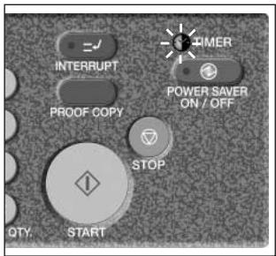

Please Be Reminded!
IMPORTANT: WHEN THE TIMER INDICATOR IS LIT, THE COPIER WILL TURN OFF AUTOMATICALLY. DO NOT TURN IT OFF BY PRESSING POWER SWITCH.
When the TIMER indicator light is on and other indicators are off, copying is unavailable due to the Weekly Timer function.
However, copying will be available by using the following procedure.
1. Press [POWER SAVER ON/OFF] on the control panel.
![KONICA MINOLTA 7255 - Press [POWER SAVER ON/OFF] on the control panel. - 1](/content/2025/01/139764/images/1bcd00329a981ec972596bf978f6a246842e55c10dfce08418b7cd402c8f0988.jpg)
![KONICA MINOLTA 7255 - Press [POWER SAVER ON/OFF] on the control panel. - 2](/content/2025/01/139764/images/12d012e4626b10fcbb2d78c689a5a8a6255c9614be01c4e302f0be86e2460324.jpg)
HINT
For details of the Weekly Timer function, see p. 13-27 to p. 13-35.
The Basic screen will be displayed along with the message shown below.
Timer interrupt mode
Enter password

FOR DETAILS
The machine power will be turned off automatically after 5 minutes from this state.
The Timer Interrupt password is not factory set and must be entered by the Key Operator.
In the event the Timer Interrupt password has not been entered by the Key Operator, the following message will display instead.
Input copy time
0 hour(s) 05 minute(s)
When the above message displays, proceed to step 4.
2. Enter the password.
Enter a 4-digit number Timer Interrupt password using the keypad on the control panel.

HINT
For setting the Timer Interrupt password, see p. 13-35.

FOR DETAILS
If an invalid password is entered, continue by entering the valid 4-digit password.
3. Press [START].
The following message will be displayed on the Basic Screen.
Input copy time
0 hour(s) 05 minute(s)
4. Set the hour for the interrupt use.
Enter a 1-digit hour (ex. 3 hours is 3) using the keypad on the control panel. (0 9)
5. Press [START].
6. Set the minute for the interrupt use.
Enter a 2-digit minute (ex. 7 minutes is 07) using the keypad on the control panel. (00 59)

FOR DETAILS
Entering a number smaller than 5 will set the minute at 5.
7. Press [START].
Copying is available until the set time is up.
8. When Timer Interrupt of the copier is finished, press [POWER SAVER ON/OFF] for one second or longer, then release it.
The copier returns to the OFF condition and copying is again disabled.
This function allows you to utilize APS or AMS and copy the original documents onto size A4 or B5, irrespective of the copy paper feeding direction.
![KONICA MINOLTA 7255 - When Timer Interrupt of the copier is finished, press [POWER SAVER ON/OFF] for one second or longer, then release it. - 1](/content/2025/01/139764/images/2e849b7853a9e1cd1ac6f660a6c279aff1e60ccb9824998be53fe55568c6e5e4.jpg)
FOR DETAILS
By default, Rotation requires APS or AMS to function. The Key Operator can set this function ON, or to operate when APS, AMS or reduce functions. See p. 13-39 to p. 13-45.
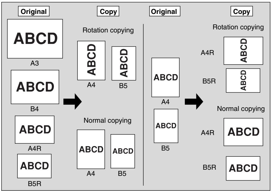
The copier is initially set to activate the Rotation function automatically. Follow the procedure below to release/resume this function.
1. Touch ROTATION OFF on the Basic Screen to highlight it.
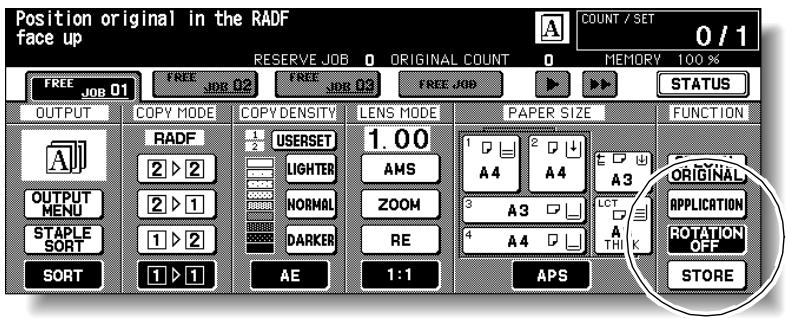
When Rotation is released, the Rotation icon on the Basic Screen will disappear to indicate that this function is cancelled.
2. Touch to deselect ROTATION OFF to resume this function.
When Rotation is resumed, the Rotation icon will be displayed on the screen.
Use the Vertical/Horizontal zoom mode to reduce or enlarge vertical and horizontal dimensions, independently.
Vertical/Horizontal Zoom Mode Specifications<<
Vertical/Horizontal zoom range: 0.25 4.00
□ Incompatible Conditions: APS, AMS, Reduce & Shift in Image Shift, Overlay with Repeat
The figure shown below is the sample image using the Vertical/Horizontal zoom.
Length: 0.50, Width: 0.50
Length: 0.50, Width: 1.00

Length: 0.50, Width: 2.00

Length: 0.50, Width: 4.00
Length: 1.00, Width: 0.50
Length: 1.00, Width: 1.00

Length: 1.00, Width: 2.00

Length: 1.00, Width: 4.00
Length: 2.00, Width: 0.50

Length: 2.00, Width: 1.00
Length: 2.00, Width: 2.00

Length: 2.00, Width: 4.00
Length: 4.00, Width: 0.50
Length: 4.00, Width: 1.00
Length: 4.00, Width: 2.00

Length: 4.00, Width: 4.00
1. Touch ZOOM on the Basic Screen.
The popup menu for setting a zoom ratio will be displayed.

Please Be Reminded!
When starting a new copying job, be sure to close the RADF securely, then press [AUTO RESET].
2. Touch Vert. on the popup menu to highlight it, then set the vertical zoom ratio.
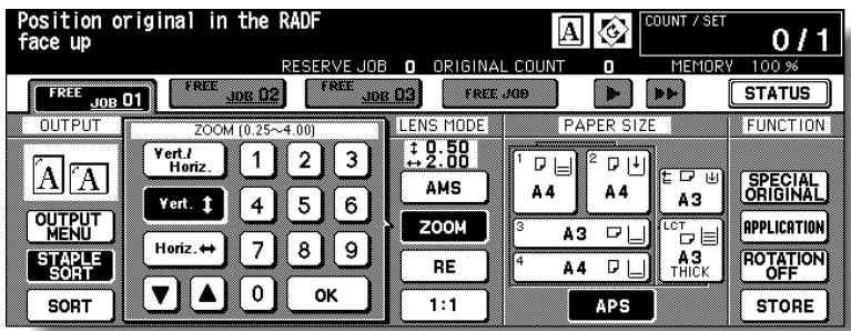
Use the keypad on the popup menu to enter a 3-digit vertical zoom ratio, or use arrow keys ( / ) to scroll to the desired ratio.
Similarly, touch Horiz. to highlight it, then set the horizontal zoom ratio.
3. Touch OK.
The popup menu disappears automatically and the specified zoom ratio will be displayed on the Basic Screen.
4. Select additional copy conditions, as desired.
5. Enter the desired print quantity from the control panel keypad.

HINT
See p. 3-6 for details on setting print quantity.
6. Position original(s).

HINT
See p. 3-2 to p. 3-5 for details on positioning originals.
7. Press [START].
![KONICA MINOLTA 7255 - Press [START]. - 1](/content/2025/01/139764/images/fd092f887e95b2a6c621a12e7cffb894e41e02883cd6c9a95447c977ad5ee823.jpg)
FOR DETAILS
The figure shown below is the sample image using the Vertical/Horizontal zoom with an original placed slantwise on the platen glass.
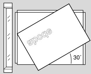

Length: 0.50, Width: 2.00
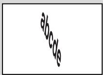
Length: 2.00, Width: 0.50
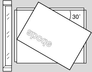

Length: 0.50, Width: 2.00
Length: 2.00, Width: 0.50
The Fold and Stitch & Fold modes are available only when the FS-210 Finisher option is installed. When either mode is selected, the Booklet feature is automatically selected and indicated on the Application Selection Screen.

FOR DETAILS
- When copying two-sided signature originals using the Fold or Stitch & Fold mode, release the automatically selected Booklet mode on the Application Selection Screen.
- When copying dark originals or using Reverse Image mode together with Fold or Stitch & Fold mode, the folded line of the output copies may be slightly shifted.
The following copy results may be expected when using Fold or Stitch & Fold mode:
In the Fold mode, each copied set is folded and output to the Booklet tray of the Finisher.
In the Stitch & Fold mode, each copied set is stapled at two positions (saddle stitched), then folded and output to the Booklet tray of the Finisher.
Specifications for Fold /Stitch & Fold Mode<<
Max. number of folded sheets (80 g/m² paper) in both modes:
3 sheets (less than in Stitch & Fold mode because they are not clinched first)
Stitch & Fold: 20 sheets 19 sheets when using thick cover paper
□ Paper size: A3, B4, A4R, 11"x17", 8.5"x14", 8.5"x11"R (60 ~ 90 g/m²)
- Booklet tray capacity:
- When the Booklet tray capacity is exceeded, the Finisher will stop operating.
- Select the appropriate print quantity by referring to the following capacities.
Approx. 100 sheets max. (A3, B4, 11"x17", 8.5"x14")
Fold: 33 sets max. of 3-sheet-folded booklet (33 x 3 = 99 sheets)
Stitch & Fold: 20 sets max. of 5-sheet-folded booklet (20 x 5 = 100 sheets)
5 sets max. of 20-sheet-folded booklet ( 5 × 20 = 100 sheets)
Approx. 75 sheets max. (A4R, 8.5"x11"R)
Fold: 25 sets max. of 3-sheet-folded booklet (25 x 3 = 75 sheets)
Stitch & Fold: 15 sets max. of 5-sheet-folded booklet (15 x 5 = 75 sheets)
Incompatible Conditions with Booklet selected: APS, 1-1, 2-1, Sort, Staplesort, Group, Rotation sort, Rotation group, Output to Secondary (sub) tray, Three-Fold, Punch, Mixed Original, Full Area in Non STD size, Tab Paper, Sheet/Cover Insertion, Combination, OHP Interleave, Program Job, NonImage Area Erase, Reverse Image, Repeat
Incompatible conditions without Booklet: Sort, Staple-sort, Group, Rotation Sort, Rotation Group, Output to Secondary (sub) tray, Three-Fold, Punch, OHP Interleave, Reverse Image
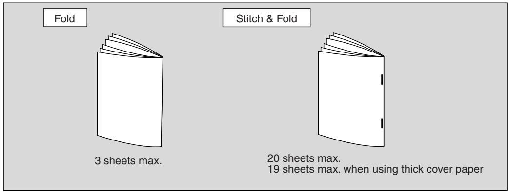
1. Touch OUTPUT MENU on the Basic Screen
The Output Mode popup menu will be displayed.
2. Touch MAIN TRAY, if not highlighted.
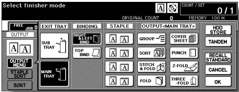
3. Touch STITCH & FOLD or FOLD, as desired.
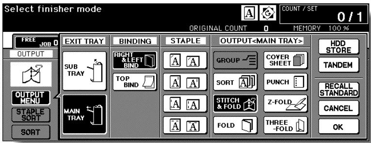

FOR DETAILS
Selecting FOLD or STITCH & FOLD will automatically switch the output tray to Booklet tray. Notice that the arrow pointing from the MAIN TRAY shifts to the Booklet tray.
4. Touch OK on the Output Mode popup menu.
The Basic Screen will be restored and the selection made in the output mode will be reflected in the OUTPUT icon area.
5. Select additional copying features, as required.

FOR DETAILS
NO COVER SHEET of Booklet is initially selected.
To change this selection, touch APPLICATION on the Basic Screen to display the Application Selection Screen, then touch Booklet twice to display the Booklet Mode Selection Screen to make another selection or to release the setting.
6. Enter the desired print quantity from the control panel keypad.

HINT
See p. 3-6 for details on setting print quantity.
7. Position original(s).

HINT
See p. 3-2 to p. 3-5 for details on positioning originals.

FOR DETAILS
When loading originals, heed the following limits on capacity:
Fold mode:
12 pages or less for simplex copying
6 pages or less for duplex copying
Stitch & Fold mode:
80 pages or less for simplex copying
40 pages or less for duplex copying
Exceeding the above capacity limits may cause trouble in the Finisher.
8. Press [START].
![KONICA MINOLTA 7255 - Press [START]. - 1](/content/2025/01/139764/images/e2ed3d8c15659fa90a94e4be750f93ffae09c1f38c39dcddae35b66f1488cca6.jpg)
CAUTION
When the Booklet tray capacity is exceeded, the Finisher will cease operating. To avoid this, select the appropriate print quantity from the specifications shown on p. 11-3.
The Punch mode is available only when the PK-110/120/120 Type-A Punching kit or PZ-108/109 Punching / Z-Folding unit option is installed in the FS-110/FS-210 Finisher, or PZ-108/109 Punching / Z-Folding unit option is installed in the FS-111 Finisher.
If both PK-110/120/120 Type-A Punching kit and PZ-108/109 Punching / Z-Folding unit are installed in the FS-110/FS-210 Finisher, the PZ-108/109 Punching / Z-Folding unit is used.
When the Punch mode is selected in combination with any of the Primary (Main) tray output modes, each copied sheet is punched and output to the Primary tray according to the selected output mode.

FOR DETAILS
- Some staple positions previously selected may conflict with this function.
- Special size paper (STD size (special), Non STD size, Wide size) cannot be punched.
- If the ATS (Automatic Tray Switching) functions while the machine uses the PK-110 Punching kit in Punch mode, the punch holes may be slightly off the appropriate positions.

Please Be Reminded!
- Do not punch special paper type such as transparent films, labels, tabbed sheets, etc. Otherwise, machine trouble may occur in Punching kit.
- Be sure that the side guide plates of the paper tray are securely aligned to the paper; otherwise the copies may not be punched in position.
>>>Specifications for Punch Mode<<
Number of holes:
PK-110/120 Punching kit; 4 holes
PK-120 Type-A Punching kit; 4 holes (Swedish type)
PZ-108 Punching / Z-Folding unit; 4 holes
PZ-109 Punching / Z-Folding unit; 2 or 4 holes (user-selective)
Hole diameter: 6.5mm± 0.5mm
Hole pitch:
80mm± 0.5mm
21 mm ± 0.5 mm / 70 mm ± 0.5 mm / 21 mm ± 0.5 mm (PK-120 Type-A)
Copy paper size:
4 holes; A3, B4, F4, A4, B5, 8.5"x11"
2 holes; A3, B4, F4, A4, A4R, B5, B5R, A5, A5R, 8.5"x11", 8.5"x11"R, 5.5"x8.5", 5.5"x8.5"R
Paper weight: 60 90 g/m^2 (80 g/m² paper recommended)
Thin paper: 50 59 g/m^2
Thick paper: 91 170^* ~g / m^2
*Some 170g / m^2 paper types may not be punched easily.
□ Incompatible Conditions: Using platen glass (available when using Platen store mode), Fold, Stitch & Fold, Three-Fold, Output to Secondary (sub) tray, Non STD Size, OHP Interleave
Incompatible Conditions with Punch mode using PK-110 Punching kit: Cover sheet feeding, Mixed Original (A4R, B5R, A5, A5R mixed and/or selecting APS mode), Sheet/Cover Insertion, Copy Insertion mode in Chapter, Cover Sheet mode in Booklet, Program Job
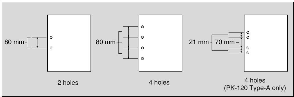
1. Touch OUTPUT MENU on the Basic Screen
The Output Mode popup menu will be displayed.
2. Touch MAIN TRAY, if not highlighted.

3. Touch PUNCH.
The Punch Position popup menu will be displayed.
4. Touch the desired punch position key on the screen to highlight it.
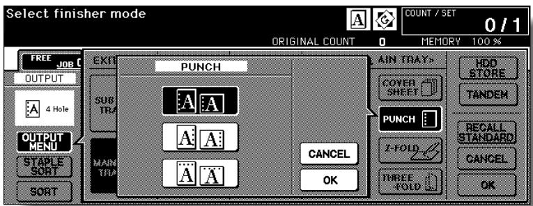
Punch Position popup menu (PZ-109)
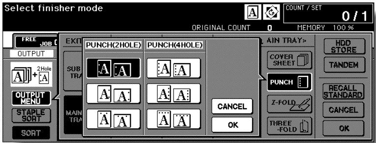
5. Touch OK on the Punch Position popup menu to restore the Output Mode popup menu.
6. Touch OK on the Output Mode popup menu to complete the setting and return to the Basic Screen.
The selection made in punch position will be displayed in the OUTPUT icon area.
7. Specify the original set direction.

Touch SPECIAL ORIGINAL on the Basic Screen to display the Special Original popup menu.
Touch to select the desired original set direction, then touch OK to return to the Basic Screen.
- Select additional copying features, as required.
- Enter the desired print quantity from the control panel keypad.

HINT
See p. 3-6 for details on setting print quantity.
- Position originals in the document feeder.

HINT
See p. 3-2 to p. 3-4 for details on positioning originals.
- Press [START].

CAUTION
When the finisher exit tray capacity is exceeded due to the print quantity selected, remove the copied sets as they exit; otherwise, mishandled paper will occur.
The Z-Fold mode is available only when the PZ-108/109 Punching / Z-Folding unit option is installed in the FS-110/111/210 Finisher.
When the Z-Fold mode is selected in combination with any of the Primary (main) tray output modes, the original image is copied on copy paper and output to the Primary (main) tray of the Finisher according to the selected output mode.
Specifications for Z-Fold Mode<<<
- Fold type: Z-fold (A3, B4, 11"x17"), double-fold (8.5"x14")
□ Paper size: A3, B4, 11"x17", 8.5"x14" (60 ~ 90 g/m² paper)
All other paper sizes will be output without Z-fold or double-fold.
- Folded width*: 209 mm or less for A3
181 mm or less for B4
215 mm or less for 11"x17"
261.6 mm or less for 8.5"x14"
- The width from the paper edge to the first folded line
□ When using Mixed Original mode with Z-Fold mode, A3 and B4 originals should not be mixed, otherwise the Z-Fold mode may not function properly.
Special paper type (Thick 2, transparent films, labels, tabbed sheets) and non-standard size (STD size (special), Non STD size, Wide paper) cannot be Z-folded. Using special paper will cause the machine trouble.
Some plain paper types may cause folded line to shift in Z-Fold mode.
□ When using Z-fold, Staple-sort and APS for mixed size originals, heed the limits on capacity described on p. 11-4.
□ Incompatible Conditions: Using platen glass (available when Platen store mode is selected), Staple-sort using B4 or 8.5"x14", Output to Secondary (sub) tray, Fold, Stitch & Fold, Tandem mode, OHP Interleave
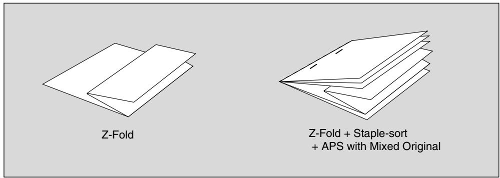
1. Touch OUTPUT MENU on the Basic Screen
The Output Mode popup menu will be displayed.
2. Touch MAIN TRAY, if not highlighted.
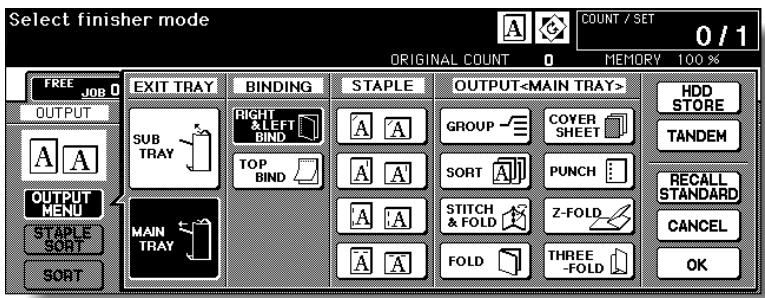
3. Touch Z-FOLD to highlight it.
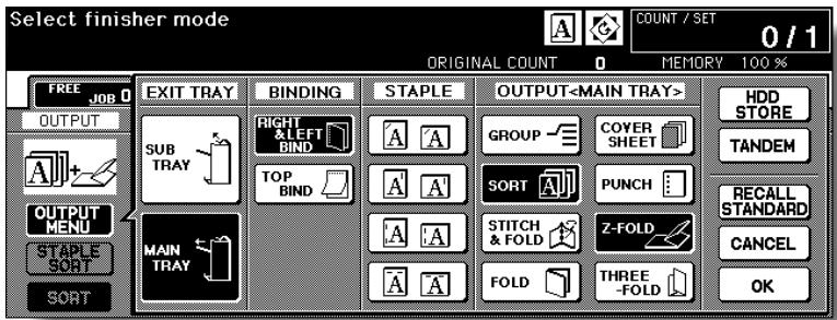
4. Touch OK on the Output Mode popup menu to complete the setting and return to the Basic Screen.
The Z-FOLD icon will be displayed in the OUTPUT icon area.
5. Select additional copying features, as required.
6. Enter the desired print quantity from the control panel keypad.

HINT
See p. 3-6 for details on setting print quantity.
7. Position originals.

HINT
See p. 3-2 to p. 3-5 for details on positioning originals.
8. Press [START].
![KONICA MINOLTA 7255 - Press [START]. - 1](/content/2025/01/139764/images/2d919ebae29e1fd4f98fbf363f40b1fa4c91bc27f05f347cec1497671c045526.jpg)
CAUTION
When the finisher exit tray capacity is exceeded due to the print quantity selected, remove the copied sets as they exit; otherwise, mishandled paper will occur.
The Three-Fold mode is available only when the FS-210 Finisher option is installed.
In this mode, the original image is copied on A4R/8.5"x11"R copy paper and output to the Booklet tray of the Finisher.
Specifications for Three-Fold Mode<<
Copy paper size: A4R, 8.5"x11"R (60 ~ 80 g/m² paper)
Number of folded sheets: 3 sheets max. (80 g/m² only)
- Booklet tray capacity: 50 sets max. of 1-sheet-folded set (50 sheets)
□ Incompatible Conditions: Sort, Staple-sort, Group, Output to Secondary (sub) tray, Fold, Stitch & Fold, Punch, OHP Interleave, Dual Page, Program Job, Reverse Image
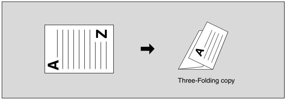
- Load A4R or 8.5"x11"R copy paper in a tray.
- Touch OUTPUT MENU on the Basic Screen
The Output Mode popup menu will be displayed.
- Touch MAIN TRAY, if not highlighted.

4. Touch THREE-FOLD to highlight it.
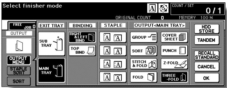
5. Touch OK on the Output Mode popup menu to complete the setting and return to the Basic Screen.
The THREE-FOLD icon will be displayed in the OUTPUT icon area.
6. Select additional copying features, as required.
Touch to highlight the A4R or 8.5"x11"R tray key, if not already highlighted.
7. Enter the desired print quantity from the control panel keypad.

HINT
See p. 3-6 for details on setting print quantity.
8. Position originals.

HINT
See p. 3-2 to p. 3-5 for details on positioning originals.
9. Press [START].
![KONICA MINOLTA 7255 - Press [START]. - 1](/content/2025/01/139764/images/aa9ed9c89810c8780c13e7a5c0877323b6ee06fa36e53b5d4ea5b13fdc53a894.jpg)
CAUTION
When the Booklet tray capacity is exceeded, the Finisher will cease operating. To avoid this, select the appropriate print quantity from the specifications shown on p. 11-3.
The Cover Sheet Feeder (PI-110) is available as an option on the FS-110/210 Finisher.
Load cover sheet paper into this device and use the sheets as front covers for copied sets output to the Main tray or use the sheets as booklet-type covers for copied sets output to the Booklet tray in the Fold, Stitch & Fold, or Three-Fold mode.

FOR DETAILS
- Paper loaded into the cover sheet feeder cannot be copied.
- This function is incompatible with cover sheet mode (COVER WITH COPY SHEET and COVER WITH BLANK SHEET) in Booklet and cover mode in Sheet/Cover Insertion.
>>>Specifications for Cover Sheet Feeding<<
Cover paper size:
Upper tray: A4, A4R, B5, B5R, A5, 8.5"x11", 8.5"x11"R, 5.5"x8.5"
Lower tray: A3, B4, A4, A4R, B5, B5R, A5, 11"x17", 8.5"x14", 8.5"x11", 8.5"x11"R, 5.5"x8.5"
*A5 and 5.5"x8.5" paper sizes are available in portrait type feeding only.
Tray capacity: 200 sheets (200 g/m² paper) or 30 mm thick for both trays
□ Incompatible Conditions: Output to Secondary (sub) tray, Punch using PK-110 Punching kit, Z-Fold, OHP Interleave
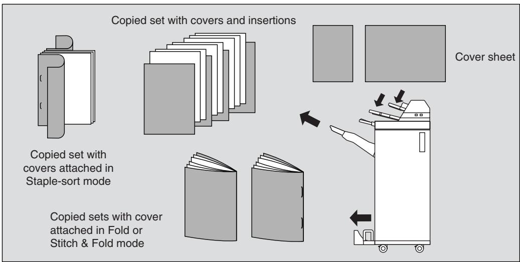
1. Touch OUTPUT MENU on the Basic Screen
The Output Mode popup menu will be displayed.
2. Touch MAIN TRAY, if not highlighted.
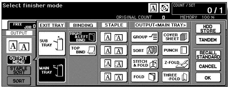
3. Touch COVER SHEET.
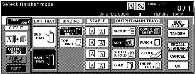
The Cover Sheet Mode Selection Screen will be displayed.
4. Touch FRONT COVER and/or BACK COVER to highlight it, then select the covers tray.
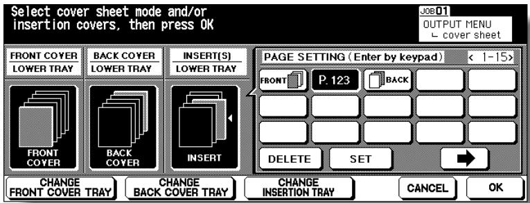
Touch CHANGE FRONT COVER TRAY and/or CHANGE BACK COVER TRAY to display the desired tray above the selected key.

FOR DETAILS
Touch and highlight FRONT COVER only, if using Fold or Stitch & Fold mode.

HINT
Copy paper sizes available to be loaded are different in each tray. See the specification on the previous page to select the appropriate tray.
If no insertions are needed, proceed to step 6.
5. Specify the insertion location.
To use cover paper for insertions, touch INSERT to highlight it. Use the control panel keypad to enter the page number of the insertion location, then touch SET to complete the entry and move to the next key.
To clear an incorrect entry, touch DELETE.
If p. 4 is entered, a cover sheet will be inserted between p. 4 and p. 5. If setting more than 15 locations including covers, touch the arrow key to move to the next page.

FOR DETAILS
- Page numbers entered out of order will be sorted automatically.
- Entering "0" or the same page number twice will be ignored on the screen.
- When a page number entered is larger than the total original page count, it will be ignored.
6. Touch OK to restore the Output Mode popup menu.
7. Touch OK on the Output Mode popup menu.
The Basic Screen will be restored.
8. Select additional copying features, as required.
9. Load the cover sheet paper into the optional cover sheet feeder of the FS-110/210 Finisher.
If the paper size loaded in the cover sheet feeder is not suitable for the selected copy conditions, the following messages will be displayed and copying will be unavailable till the correct size is loaded.
Please load cover sheet in cover sheet feeder
Adapt paper size between cover sheet and selected paper
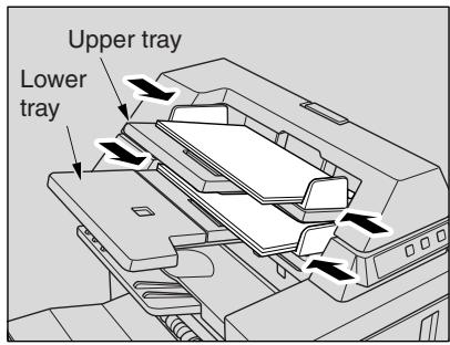
10. Enter the desired print quantity from the control panel keypad.

HINT
See p. 3-6 for details on setting print quantity.
11. Position originals.

HINT
See p. 3-2 to p. 3-5 for details on positioning originals.
12. Press [START].
![KONICA MINOLTA 7255 - Press [START]. - 1](/content/2025/01/139764/images/9275343a1f19be6b3fe3e3c04e161a6aab7ecb7ff7ed48eab28677c80e5850ef.jpg)
CAUTION
When the finisher exit tray capacity is exceeded due to the print quantity selected, remove the copied sets as they exit; otherwise, mishandled paper will occur.
This function is available only with the Cover Sheet Feeder option (PI-110) installed on the FS-110/210 Finisher. To use this convenient function, simply place a set of paper into the lower tray of the cover sheet feeder, select the desired mode from the Manual Finishing operation panel located on the top of the Finisher, then press the Start/Stop button.
Available finishing modes according to the optional configuration are described below.
FS-110 Finisher + PI-110 Cover Sheet Feeder
1 oblique staple
2 parallel staples
FS-110 Finisher + PI-110 Cover Sheet Feeder + PK-110/120/120 Type-A Punching Kit
1 oblique staple
2 parallel staples
Punch
FS-210 Finisher + PI-110 Cover Sheet Feeder
1 oblique staple
2 parallel staples
- Stitch & Fold (2 staples in the centre + Fold)
Three-Fold
FS-210 Finisher + PI-110 Cover Sheet Feeder + PK-110/120/120 Type-A Punching Kit
1 oblique staple
2 parallel staples
- Stitch & Fold (2 staples in the centre + Fold)
Three-Fold
- Punch
Specifications for Manual Staple 1 oblique staple and 2 parallel staples<<
□ Paper size: A3, B4, A4, A4R, B5, B5R, A5*, 11"x17", 8.5"x14", 8.5"x11", 8.5"x11"R
*A5 paper is available in portrait type feeding only.
Paper weight: 50 200 g/m^2
Staple capacity: 50 sheets max.
Output tray: Primary (main) tray
Specifications for Manual Punch<<
Paper size: A3 to B5
Paper weight: 50 170^ g/m²
*: Some 170 g/m^2 paper types may not be punched easily.
Punch capacity: 200 sheets max. (200 g/m² paper) or within 30 mm thick
Output tray: Primary (main) tray
The machine with PZ-108/109 Punching / Z-Folding unit requires PK-110/ 120/120 Type-A Punching kit to use this function.
Specifications for Manual Stitch & Fold mode<<
□ Paper size: A3, B4, A4R, 11"x17", 8.5"x14", 8.5"x11"R
Paper weight: 60 200 ~g / m^2
Staple capacity: 20 sheets max. (80g/m² paper)
19 sheets max. (80g/m² paper with a thick paper cover)
Output tray: Booklet tray
Specifications for Three-Fold mode<<
Paper size: A4R, 8.5"x11"R
Paper weight: 60 80g / m^2
Folding capacity: 3 sheets max. (80g/m² only)
Output tray: Booklet tray
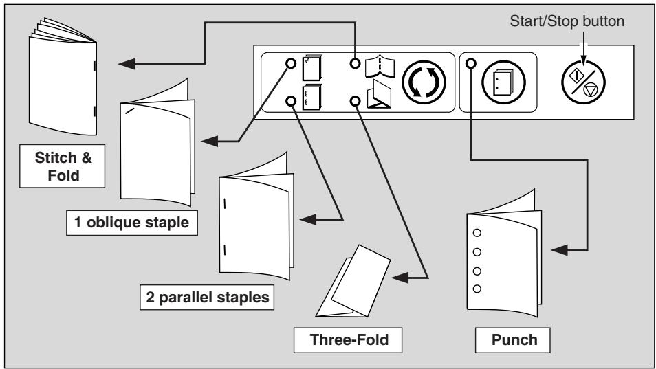
1. Place a set of paper to be finished into the lower tray of the cover sheet feeder, as described below for each mode.
1 oblique staple / 2 parallel staples: FACE UP
- Punch: FACE UP
- Stitch & Fold:
FACE UP for the outside of the finished set
Three-Fold:
FACE UP for the outside of the folded set Align the guide plate. The indicator light of Start/Stop button will turn green.
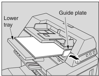

HINT
Refer to the specifications for available paper size and capacity in each mode.

Please Be Reminded!
Do not punch special paper type such as transparent films, labels, tabbed sheets, etc. Otherwise, machine trouble may occur in Punching kit.
2. Press Staple Mode Selection button and/or Punch button to select the desired mode.
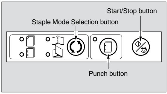

FOR DETAILS
Punch mode is compatible with 1 oblique staple, 2 parallel staples, or Stitch & Fold mode.
3. Press Start/Stop button.
Finished sheets will be delivered to the appropriate tray according to the selected mode.

FOR DETAILS
If you want to stop the Manual Finishing operation, press the Start/Stop button again. The Finisher will cease operating. When using Stitch & Fold mode, the unfinished set will be left in the stacker unit inside the Finisher.

CAUTION
When the finisher exit tray capacity is exceeded due to the print quantity selected, remove the copied sets as they exit; otherwise, mishandled paper will occur.
Tandem mode enables your 7255/7272 primary (master) copier to work in tandem with the 7255/7272 secondary (sub) copier for the purpose of providing faster completion of large copying jobs. Two units working in tandem distribute a job in half the time of non-tandem mode.
Service setting is required to use the tandem mode. Contact your service representative, if desired.
>>>Specifications for Tandem Mode<<
The two copiers should be connected in either way described below.
(1) Connect the two copiers directly using a crossover cable. In this case, other network functions provided to the copier will be unavailable.
(2) Connect each of the two copiers to the hub in a network using straight-through cables.
Use the straight-through or crossover cables of Category 5 or of the later standard to connect the machines.
The combination of the two copiers can be either the same models (two 7255 copiers or two 7272 copiers) or different models (7255 and 7272).
- Two copiers should have the same optional configuration except for the option tray (LT-402/LT-412).
Two copiers should be turned on and ready for copying.
The copier with the TANDEM key highlighted on the Output Mode popup menu will be the primary (master) copier, turning both copiers into the tandem mode.
Select the copying conditions, scan originals, and press [START] on the primary copier to operate both copiers in tandem to complete a job.
-
Print quantity must be set for [2] or more copies to activate the tandem mode. When the print quantity entered is an odd number, the primary copier will copy and output one sheet/set more than the secondary copier to accommodate the job.
Auto low power/Auto shut-off may function while tandem mode is selected. -
If the tandem mode is selected while the secondary copier is in Auto low power mode, the power saving mode will be released automatically.
- The tandem mode will not be selected when the secondary copier is turned off by Auto shut-off. Release the Auto shut-off mode by pressing [POWER SAVER ON/OFF].
- If Auto low power is activated on the secondary copier during the tandem job setting, the power saving mode will be released automatically when printing job starts.
- If Auto shut-off is activated on the secondary copier during the tandem job setting, the tandem mode will be released automatically.
- If Auto low power/Auto shut-off is activated on the primary copier, the tandem mode will be released automatically.
Auto reset may function while tandem mode is selected.
Initially, the tandem mode will be released automatically if Auto reset is activated on the primary copier.
Key operator can set the primary copier to select the tandem mode as initial setting. Apply this setting to the primary copier only, if desired. Setting on both copiers will deactivate the tandem mode.
The 7255/7272 is provided with an Allocation recovery mode, which functions when trouble occurs in either the primary or secondary copier to allow the trouble-free copier to complete the job.
- When the two copiers in tandem mode have the same EKC password registered, copying will be available by entering the EKC password in the primary copier only. The password will be transmitted to the secondary copier.
Interrupt copying is available only on the copier with [INTERRUPT] pressed.
□ If the primary copier is installed with HDD, the image data stored in HDD can be output in tandem mode copying.
□ Corresponding tray sizes on the primary and secondary copiers should be the same when using multiple trays for a single job.
Incompatible Conditions: Rotation Sort, Rotation Group, Group, Rotation, OHP Interleave, SET NUMBERING and WATERMARK NUMBERING in Stamp
1. Turn power on by pressing the Power switches of the two copiers.
Confirm that both copiers are ready to copy with the Basic Screen displayed.
2. Touch OUTPUT MENU on the Basic Screen of either copier.
The Output Mode popup menu will be displayed.
3. Touch TANDEM to highlight it, then touch OK.
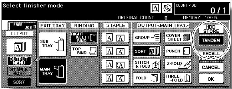
The copier with TANDEM highlighted will become the primary copier; the other copier will function as the secondary copier. The Master icon displays on the Basic Screen of the primary copier to indicate that the two units are ready to work in tandem mode.
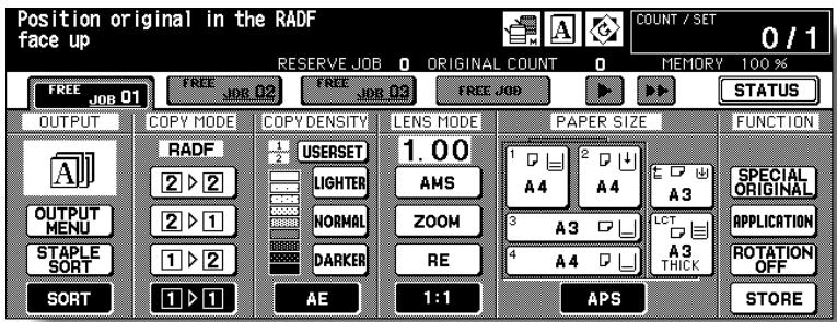

FOR DETAILS
The Sub icon will display on the Basic Screen of the secondary copier when [START] is pressed on the primary copier to start the tandem printing operation.

FOR DETAILS
The tandem mode cannot be selected/continued in the cases shown below. The message "Please wait/ Reserve is not available in Sub machine," "Sub machine error/ Please check sub machine," or "Please check sub machine" will be displayed, as required.
- The tandem mode cannot be selected while the secondary copier is in the off state, due to Auto shut-off. Press [POWER SAVER ON/OFF] to release it.
- Selected tandem mode will be released automatically when the secondary copier activates Auto shut-off. Press [POWER SAVER ON/OFF] to release it, then select the tandem mode again to restart the procedure.
- When any problem occurs in the secondary copier, such as a paper misfeed or lack of paper, the secondary copier will be unavailable for printing; however, the problem will not cause tandem mode to be released. Take the appropriate troubleshooting measures to be ready for copying.
- Tandem printing job cannot be started if 10 reserve jobs (not in tandem mode) are entered on the secondary copier. Wait until the reserve jobs are completed on the secondary copier.
- Selected tandem mode will be released automatically when the primary copier activates Auto low power/Auto shut-off.
Press [POWER SAVER ON/OFF] to release Auto shut-off if required, then select the tandem mode again to restart the procedure.
4. Select the desired copying conditions on the primary copier.

FOR DETAILS
Ordinary copying operation is still available on the secondary copier during the tandem mode setting.
5. Enter print quantity on the primary copier, using the keypad.
When a print quantity amount of 100 is entered, the primary and secondary copiers will each copy and output 50 sheets.

FOR DETAILS
- Print quantity must be set for [2] or more copies to activate the tandem mode.
- When the print quantity entered is an odd number, the primary copier will copy and output one sheet/set more than the secondary copier to accommodate the job.
6. Position original(s) FACE UP in the document feeder or FACE DOWN on the platen glass of the primary copier.

HINT
See p. 3-2 to p. 3-5 for details on positioning originals.
7. Press [START] on the control panel of the primary copier.
The Sub icon ( ) will display on the Basic Screen of the secondary copier to indicate that the two copiers will start working in tandem.
The tandem mode will be released automatically when the tandem mode copying is completed, and the Master and Sub icons on each Basic Screen will disappear.
![KONICA MINOLTA 7255 - Press [START] on the control panel of the primary copier. - 1](/content/2025/01/139764/images/2c23ccc1fc12d1c0a048b7e2d7fa45fdd2d6b490d54d89ed7e6b4deca11e0a54.jpg)
FOR DETAILS: Entering reserve job during Tandem mode copying
If scanning of the next reserved job is performed during the tandem mode copying, that job will also be performed in the tandem mode. Up to 10 jobs including the present job can be reserved.
Interrupt mode during Tandem mode copying
Interrupt copying is available only on the copier with [INTERRUPT] pressed. The tandem mode copying on the copier in interrupt mode will be suspended until the interrupt copying is completed.
If the interrupt mode period is of long standing, the Allocation recovery mode will activate to enable the other copier to handle the remaining print quantity.
To Stop Scanning/Printing
To cancel the tandem copying job:
1. Press [STOP] on the control panel of the primary copier.
The scanning/printing job stops immediately, and the popup menu appears on the Basic Screen of the primary copier to ask you whether to continue or terminate the job. At this time, the tandem mode is not released.
![KONICA MINOLTA 7255 - Press [STOP] on the control panel of the primary copier. - 1](/content/2025/01/139764/images/e2f1735a3bf1869a58a60ed56e14aba328176331927fde57b0caa8e117b3a1e6.jpg)
2. Touch CONTINUE to go on, or EXIT to delete all the scanned data and to release the tandem mode.
To cancel the job in the secondary copier only:
1. Press [STOP] on the control panel of the secondary copier.
The secondary copier stops the current operation immediately, and the popup menu appears on the Basic Screen of the secondary copier to ask you whether to continue or cease the operation. At this time, the tandem mode is not released.
![KONICA MINOLTA 7255 - Press [STOP] on the control panel of the secondary copier. - 1](/content/2025/01/139764/images/24e9a9ef5081da9e03a7afacd51bef92e4aebf89f77d039d737bca850cbbef6b.jpg)
FOR DETAILS
If temporary suspension in the secondary copier takes a long time, the Allocation recovery mode will activate, enabling the primary copier to handle the remaining print quantity.
2. Touch CONTINUE to go on, or EXIT to delete all the data transmitted to the secondary copier and to release the tandem mode.
The primary copier will take over the remaining print quantity and complete the job.

FOR DETAILS
Once the Allocation recovery mode is activated and the primary copier is already handling the remaining print quantity, the secondary copier cannot continue with the tandem printing job, even when CONTINUE is touched on the popup menu.
Troubleshooting
Copying with the Allocation recovery mode:
The Allocation recovery mode enables you to complete your copying job even when trouble occurs in either the primary or secondary copier, such as a paper jam.
In that case, the copier that is trouble free completes the job.

FOR DETAILS
The copier is initially set to activate this function. Contact your service representative, if you do not require this function.
When a paper jam, SC-code (E-code, F-code) trouble or unloaded paper occurs on either the primary or secondary copier:
The copier that is trouble free handles the remaining print quantity and completes the job.
When the job is completed, take the appropriate troubleshooting measures to correct the problem.
When memory overflow occurs on either the primary or secondary copier:
On the primary copier
The scanning job will stop immediately, and the tandem copying job will be suspended on both copiers. At this time, the tandem mode is not released.
Take the same measure to be applied for single copier referring to p. 5-11 ~ p. 5-12.
On the secondary copier
The secondary copier will start the tandem copying job when the memory becomes available after completing some reserve jobs. In this case, the Allocation recovery mode functions to continue the tandem printing job on the primary copier until the secondary copier becomes available for the job.
If the memory of the secondary copier cannot be available despite the elapse of time, the tandem mode will be released on the secondary copier, and the Allocation recovery mode functions to complete the job on the primary copier.
When the power is turned off on either the primary or secondary copier:
The tandem mode will be released automatically in either case. Restart the procedure from the first step.
SECTION
8
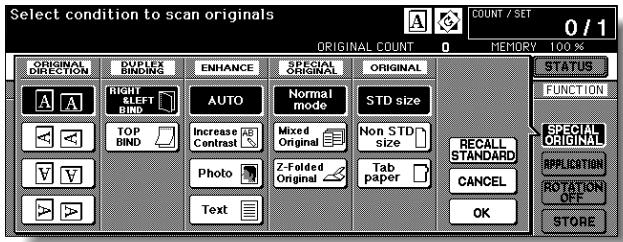
Special Original
How to Make a Copy of Special Original
Specifying Original Direction 8-2
Selecting Original Binding Direction 8-4
Making Copy Quality Closer to Originals (Text/Photo Enhance) ....8-6
Copying Mixed Size Originals (Mixed Original) 8-8
Copying Z-Folded Originals (Z-Folded Original) 8-10
Copying Non-Standard Size Originals (Original Form) 8-12
Specify the direction of the originals placed on RADF or platen glass.
This setting is required to obtain copy results as expected when making double-sided copies with binding position specified or when staple position is specified.
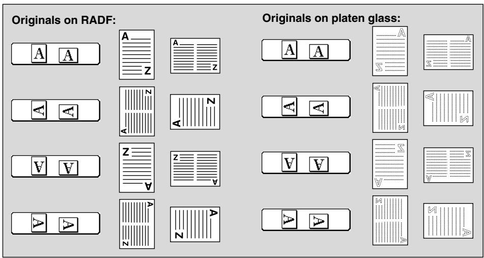
1. Touch SPECIAL ORIGINAL on the Basic Screen.
The Special Original popup menu will be displayed.

Please Be Reminded!
When starting a new copying job, be sure to close the RADF securely, then press [AUTO RESET].
2. Touch to highlight the desired original direction key.
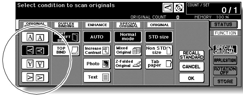
3. Touch OK to complete the setting and return to the Basic Screen.
The SPECIAL ORIGINAL key on the Basic Screen is highlighted, and the icon in the message area indicates the selected original direction.
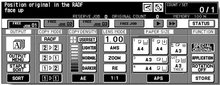
- Make other compatible selections.
- Enter the desired print quantity from the control panel keypad.

HINT
See p. 3-6 for details on setting print quantity.
- Position originals FACE UP in the document feeder or FACE DOWN on the platen glass according to the original direction specified in step 2.

HINT
See the illustration on previous page, and p. 3-2 to p. 3-5 for details on positioning originals.
- Press [START].

CAUTION
When the finisher / shift tray / paper exit tray capacity is exceeded due to the print quantity selected, remove the copied sets as they exit; otherwise, mishandled paper will occur.
When copying in 2-1 or 2-2 mode, specify the binding direction of the originals on the Special Original popup menu to obtain the desired copy result. RIGHT&LEFT BINDING is initially selected to make copies in the same direction as the originals.
1. Touch SPECIAL ORIGINAL on the Basic Screen.
The Special Original popup menu will be displayed.

Please Be Reminded!
When starting a new copying job, be sure to close the RADF securely, then press [AUTO RESET].
2. Touch to highlight the desired binding direction key.
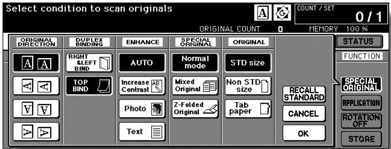
3. Touch OK to complete the setting and return to the Basic Screen. The SPECIAL ORIGINAL key on the Basic Screen is highlighted.
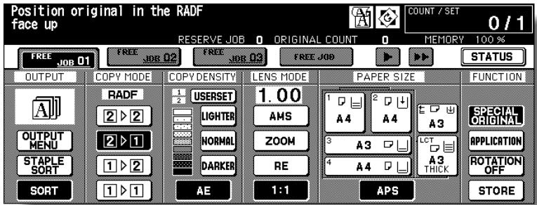
4. Make other compatible selections.
5. Enter the desired print quantity from the control panel keypad.

HINT
See p. 3-6 for details on setting print quantity.
6. Position originals FACE UP in the document feeder or FACE DOWN on the platen glass.

HINT
See p. 3-2 to p. 3-5 for details on positioning originals.
7. Press [START].
![KONICA MINOLTA 7255 - Press [START]. - 1](/content/2025/01/139764/images/ba5e268fa12a468ccdf1d07922410b0e93286379d80d13e3181a29e77a74ace6.jpg)
CAUTION
When the finisher / shift tray / paper exit tray capacity is exceeded due to the print quantity selected, remove the copied sets as they exit; otherwise, mishandled paper will occur.
Making Copy Quality Closer to Originals (Text/ Photo Enhance)
Use this function to enhance the reproducibility of half tones so that the copy quality more closely matches to that of the original.
Text Mode
Use the Text mode when copying a text original. In this mode, text is improved in comparison to using the general mode.
Photo Mode
Use the Photo mode to reproduce a half-tone photo image. The copy will closely represent the half-tones of the original image.
Increase Contrast Mode
Select Increase Contrast to darken lightly printed images (e.g., pencil) without changing background exposure. In cases where the image is light and background is dark, the background will not be changed.

FOR DETAILS
In each enhance mode, the copy density level can be shifted three levels darker or three levels lighter (Density Shift). See p. 3-20 if this setting is desired.
Specifications for Text/Photo Enhance<<
Incompatible Copying Conditions: None
Original

Auto mode
Photo mode

Original
Auto mode
Text mode
Original

Auto mode
Increase contrast mode
1. Touch SPECIAL ORIGINAL on the Basic Screen.
The Special Original popup menu will be displayed.

Please Be Reminded!
When starting a new copying job, be sure to close the RADF securely, then press [AUTO RESET].
2. Touch Text, Photo, or Increase Contrast, as required.
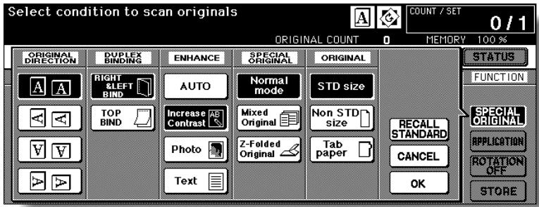
- Touch OK to return to the Basic Screen.
- Select additional copying features, as desired.
- Enter the desired print quantity from the control panel keypad.

HINT
See p. 3-6 for details on setting print quantity.
6. Position original(s) FACE UP in the document feeder or FACE DOWN on the platen glass.

HINTS
- See p. 3-2 to p. 3-5 for details on positioning originals.
- Use RADF store mode (p. 3-33 to p. 3-34) when the original count exceeds 100.
7. Press [START].
![KONICA MINOLTA 7255 - Press [START]. - 1](/content/2025/01/139764/images/4a8078b941898674c0f0ce814733477e4c2b84680923551c7af2522885b97d8c.jpg)
CAUTION
When the finisher / shift tray / paper exit tray capacity is exceeded due to the print quantity selected, remove the copied sets as they exit; otherwise, mishandled paper will occur.
Use the Mixed original mode with the document feeder or with Store mode to copy mixed size originals.
Each original in the mixed set will be copied to paper of the same size (APS mode) or to paper of desired size with appropriate ratio automatically selected (AMS mode).
>>>Specifications for Mixed Original<<
Use RADF.
Combination of original sizes to be mixed depends on the width of the RADF original guides. See p. 11-9 to p. 11-10 for details.
Incompatible Conditions: Staple-Sort with APS, Rotation Sort, Fold, Stitch & Fold, Three-Fold, Punch using PK-110 Punching kit (B6R mixed and/or selecting APS mode), Z-Folded Original, Non STD Size, Tab Paper, Sheet/ Cover Insertion, Chapter, Combination, Booklet, OHP Interleave, Image Insert, Dual Page, Program Job, Non-Image Area Erase, Repeat, AUTO Layout, Overlay, Storing image in Overlay Memory
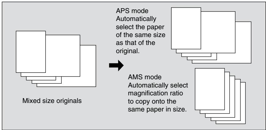
1. Touch SPECIAL ORIGINAL on the Basic Screen.
The Special Original popup menu will be displayed.

Please Be Reminded!
When starting a new copying job, be sure to close the RADF securely, then press [AUTO RESET].
2. Touch Mixed Original.
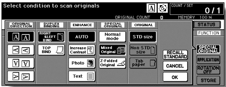
- Touch OK to return to the Basic Screen.
- Select additional copying features, as desired.

FOR DETAILS
APS is automatically selected on the Basic Screen.
To select AMS, touch the tray key on the Basic Screen to select the desired paper size.
- Enter the desired print quantity from the control panel keypad.

HINT
See p. 3-6 for details on setting print quantity.
- Position mixed original(s) FACE UP in the document feeder.

HINTS
See p. 3-3 for details on positioning originals.
- Use RADF store mode (p. 3-33 to p. 3-34) when the original count exceeds 100.
- Press [START].

CAUTION
When the finisher / shift tray / paper exit tray capacity is exceeded due to the print quantity selected, remove the copied sets as they exit; otherwise, mishandled paper will occur.
Copying Z-Folded Originals (Z-Folded Original)
Use the Z-folded original mode with the document feeder to copy Z-folded originals. Otherwise, the size detection sensor of the RADF may function incorrectly.
This mode requires more scanning time to detect the original size.
Specifications of Z-Folded Original<<
Use RADF.
Incompatible Conditions: Using platen glass, Mixed Original, Non STD Size, Tab Paper, Non-Image Area Erase, Repeat, AUTO Layout, Storing image in Overlay Memory
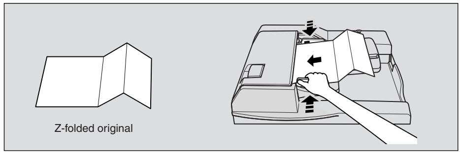
1. Touch SPECIAL ORIGINAL on the Basic Screen.
The Special Original popup menu will be displayed.

Please Be Reminded!
When starting a new copying job, be sure to close the RADF securely, then press [AUTO RESET].
2. Touch Z-Folded original.
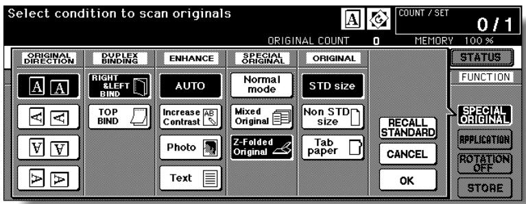
- Touch OK to return to the Basic Screen.
- Select additional copying features, as desired.
5. Enter the desired print quantity from the control panel keypad.

HINT
See p. 3-6 for details on setting print quantity.
6. Position mixed original(s) FACE UP in the document feeder.

FOR DETAILS
Normal originals can also be loaded at the same time.

HINTS
See p. 3-4 for details on positioning originals.
- Use RADF store mode (p. 3-33 to p. 3-34) when the original count exceeds 100.
7. Press [START].
![KONICA MINOLTA 7255 - Press [START]. - 1](/content/2025/01/139764/images/f29c881898260a046442714818673067879e42dfe799607fe935e77473b512e7.jpg)
CAUTION
When the finisher / shfit tray / paper exit tray capacity is exceeded due to the print quantity selected, remove the copied sets as they exit; otherwise, mishandled paper will occur.
The copier usually detects the standard size of originals fed through RADF or positioned on the platen glass (STD size mode).
Use Non STD size mode to specify the scanning area manually for copying or printing special size originals. Use Tab paper mode to copy a tabbed original, including the image of the tab part, onto tabbed copy paper.
>>>Specifications of Original Form<<
Tab extension width: 12.5 mm or less
Incompatible with Non STD Size: Mixed Original, Z-Folded Original, Tab Paper, Storing image in Overlay Memory
□ Incompatible with FULL AREA: Combination, Booklet, Dual Page, Non-Image Area Erase, Image Shift
□ Incompatible with Tab Paper: Mixed Original, Z-Folded Original, Non STD Size, Sheet/Cover Insertion, Chapter, Combination, Booklet, OHP Interleave, Image Insert, Dual Page, Storing image in Overlay Memory
1. Touch SPECIAL ORIGINAL on the Basic Screen.
The Special Original popup menu will be displayed.

Please Be Reminded!
When starting a new copying job, be sure to close the RADF securely, then press [AUTO RESET].
2. Touch Non STD Size or Tab paper.
The popup menu will appear for Non STD size or Tab paper size setting.
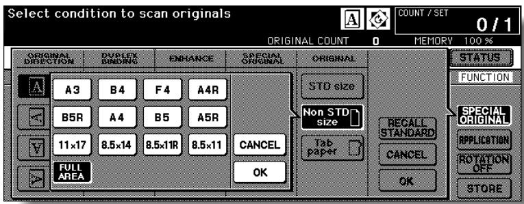
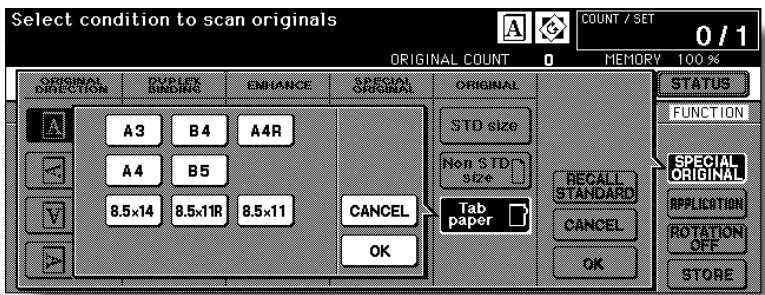
3. Touch the desired size key.

FOR DETAILS
When selecting FULL AREA on the Non STD size mode menu, the copier scans the whole area of the platen glass and copies with the paper size or magnification ratio currently selected.
4. Touch OK on the popup menu to complete the setting.
The popup menu will disappear.
5. Touch OK to complete the setting and return to the Basic Screen.
6. Load copy paper.

HINTS
- To load tabbed copy paper in the Multi-sheet bypass tray, specify the paper type as Tab paper. See p. 3-29 to p. 3-32.
To load tabbed copy paper in any other tray, specify the paper type as Tab paper in the Key Operator mode. See p. 13-23 to p. 13-24. - For the procedure of tabbed copy paper supply, see p. 2-31 to p. 2-33.
7. Enter the desired print quantity from the control panel keypad.

HINT
See p. 3-6 for details on setting print quantity.
8. Position original(s) FACE UP in the document feeder, or FACE DOWN on the platen glass.

HINTS
- See p. 3-3 to p. 3-5 for details on positioning originals.
- Use RADF store mode (p. 3-33 to p. 3-34) when the original count exceeds 100.
9. Press [START].
![KONICA MINOLTA 7255 - Press [START]. - 1](/content/2025/01/139764/images/9c3810ab96451854c3733b65dcdc835afc8acfb20134cb3cf1427db25b95e24b.jpg)
CAUTION
When the finisher / shift tray / paper exit tray capacity is exceeded due to the print quantity selected, remove the copied
sots as they exit; otherwise, mishandled paper will soon
SECTION
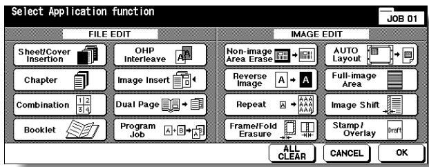
9
Applications
How to Use Application Functions
To Display Application Selection Screen 9-2
Inserting Sheets and Covers (Sheet/Cover Insertion) 9-3
Locating Title Pages on the Right Side (Chapter) 9-7
Lay Out Several Pages onto One Sheet (Combination) 9-10
Making a Multiple Page Signature Booklet (Booklet) 9-13
Copying onto Transparent Films (OHP Interleave) 9-17
Inserting Images into Printed Sets (Image Insert) 9-19
Dividing an Image into Right and Left Pages (Dual Page) 9-22
Programming Different Settings for an Output Job (Program Job) ....9-26
Erasing Outside of the Original (Non-Image Area Erase)............9-29
Reversing Colour in Black and White Image (Reverse Image) ......9-31
Repeating Selected Image Area (Repeat: Vert./Horiz. Mode) .....9-33
Repeating Automatically Or Selecting Repeating Times(Repeat:
AUTO/ Repeat Mode) 9-36
Eliminating Black Copy Marks Along Borders (Frame/Fold Erasure).9-39
Copying Image in the Centre of Copy Paper (AUTO Layout)......9-42
Printing Images Fully to the Edges (Full-Image Area) 9-44
Adjusting Position of Copy Image (Image Shift) 9-46
Reducing Images to Create Binding Margin (Reduce&Shift) 9-49
Printing Stamp, Page, Date/Time onto Copies (Stamp) 9-52
Printing Watermark onto Copies (Stamp) 9-58
Overlaying an Image onto Each Page Copied in the Job (Overlay) 9-61
Storing an Overlay Image in HDD / Overlaying Image Stored in HDD (Overlay Memory) 9-64
Follow the procedure below to display the Application Selection Screen and select the desired copying features.
1. Touch APPLICATION on the Basic Screen.
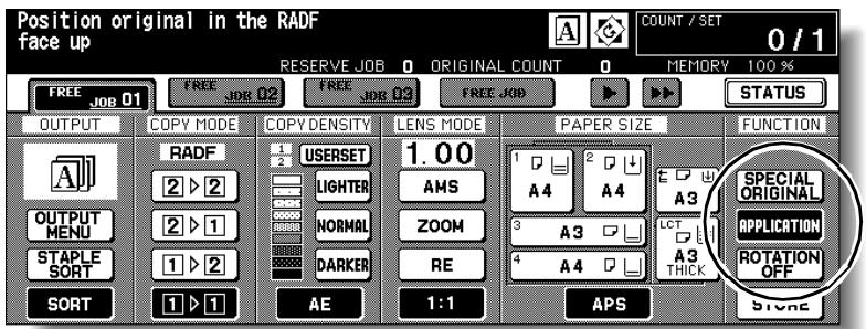
The Application Selection Screen will be displayed on the touch panel.


FOR DETAILS
- When a function key is touched, it becomes highlighted. If you touch a function key, another screen or two will display to enable you to enter the appropriate settings.
- Check BOOK MARK in the message area of the subsequent screen, if desired, so that the screen may be directly accessed from the Check Screen to change the setting you made.
- If one function on the menu is incompatible with another, it will appear dimmed.
- The APPLICATION key on the Basic Screen will be highlighted when application selections have been made.
To restore the original copying conditions, touch CANCEL.
To clear all Application settings, touch ALL CLEAR.
2. Touch OK on the Application Selection Screen.
Selections will be completed and the Basic Screen will be restored.

Please Be Reminded!
With the Basic Screen displayed, you can press [START] to perform the operation.
Inserting Sheets and Covers (Sheet/Cover Insertion)
Use Sheet/Cover Insertion in copy mode or blank mode to insert chapter sheets or separator sheets into the finished set, as well as front and back covers.
>>>Specifications for Sheet/Cover Insertion<<
Use RADF.
Trays for copy paper, front/back covers, and insertions should have the same paper size loaded. AMS (Automatic Magnification Selection) is automatically selected.
Max. insert sheets: 30 locations, from 1~999, including front and back covers
□ Incompatible Conditions: APS, Group, Rotation Sort, Rotaion Group, Punch with PK-110 Punching kit, Mixed Original, Tab Paper, Combination, Booklet, OHP Interleave, Image Insert, Dual Page, Program Job, Non-image Area Erase, Repeat except 2/4/8 Repeat, AUTO Layout, Overlay, Storing image in Overlay Memory
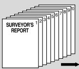
FRONT COVER COPIED
Originals
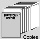
Copies

BACK COVER COPIED
Originals
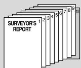
Copies
COPY SHEET INSERTION
Originals

Copies
Combination samples:
FRONT & BACK COVERS COPIED, AND COPY SHEET INSERTION
FRONT COVER BLANK
Originals
BACK COVER BLANK
Originals
Copies
BLANK SHEET INSERTION
Originals

Copies
FRONT & BACK COVERS BLANK, AND BLANK SHEET INSERTION
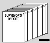
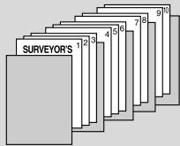
- Load regular sheets into any tray, and insertion sheets and covers into each tray source to be designated on the Sheet/Cover Insertion Screen.

FOR DETAILS
- When using thick paper or tabbed paper for covers or insertions, load them in the Multi-sheet bypass tray, unless previously specified and loaded in any other tray.
-
Be sure that the trays for copy paper, front/back covers, and insertions should have the same paper size loaded.
-
Touch APPLICATION on the Basic Screen.

Please Be Reminded!
When starting a new copying job, be sure to close the RADF securely, then press [AUTO RESET].
- Touch Sheet/Cover Insertion on the Application Selection Screen.
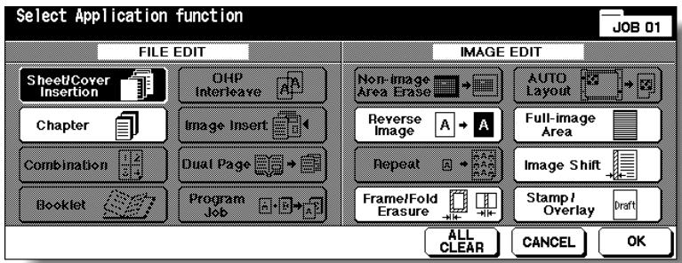
The Sheet/Cover Insertion Screen will be displayed.
- Select the desired cover mode.
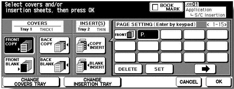
Example: Touch FRONT COPY to insert a copied front cover.
5. Touch CHANGE COVERS TRAY to select the cover sheet tray source.
The tray source for covers currently selected is displayed on the Sheet/Cover Insertion Screen.
Every touch of the key shifts the selection in the display that includes paper type as specified in Key Operator mode.
If no insertion is desired, proceed to step 8.
6. When selecting Insertion mode: Enter the page number.
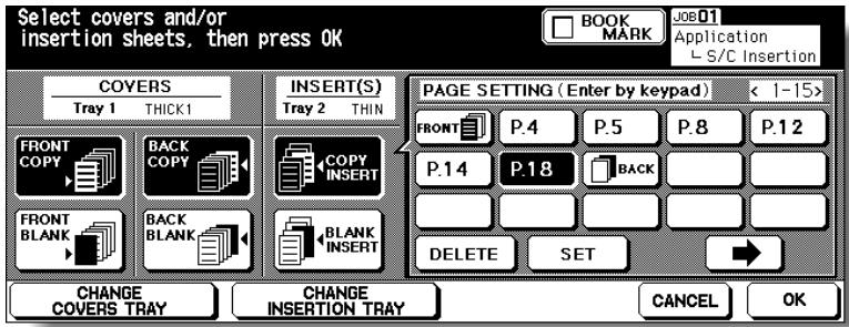
Touch to select the desired insertion mode, then use the control panel keypad to enter the page number of insertion location.
Touch SET after each entry to move to the next key.
To clear an incorrect entry, touch DELETE. The insertion location will be deleted.

HINT
See p. 9-6 for details on entering page numbers.
7. Touch CHANGE INSERTION TRAY to select the insertion tray source.
The tray source for covers currently selected is displayed on the Sheet/Cover Insertion Screen.
Every touch of the key shifts the selection in the display that includes paper type as specified in Key Operator mode.
8. When all settings are completed, touch OK to return to the Application Selection Screen.
The Basic Screen will be restored.
9. Enter the desired print quantity from the control panel keypad.

HINT
See p. 3-6 for details on setting print quantity.
10. Position originals FACE UP in the document feeder.

HINTS
- For details on positioning originals, see p. 3-2.
- Use RADF store mode (p. 3-33 to p. 3-34) when the original count exceeds 100.
11. Press [START].
![KONICA MINOLTA 7255 - Press [START]. - 1](/content/2025/01/139764/images/753db9419ca2001e83590ed522e4a39547e105f3c54fd95feca3497d66393084.jpg)
CAUTION
When the finisher / shift tray / paper exit tray capacity is exceeded due to the print quantity selected, remove the copied sets as they exit; otherwise, mishandled paper will occur.

FOR DETAILS: Entering Page Numbers
Fifteen keys are displayed on the screen to designate each insertion location. When setting more than 15 locations, touch the arrow key to move to the next page.
The first (upper left) key displays the Front Cover icon if selected. The Back Cover icon appears, if selected, as the last (fixed) key, with one active blank key preceding it.
Example: If p. 4 is entered in blank mode, a blank sheet will be inserted between p. 4 and p. 5; in copy mode, a copied sheet is inserted at p. 4.
NOTES:
- The page numbers entered at random will be sorted automatically.
- Entering "0" or the same page number twice will be ignored on the screen.
- When a page number entered is larger than the total original page count, it will be ignored.
Locating Title Pages on the Right Side (Chapter)
Chapter is used with RADF in 1-2 mode for the purpose of locating title pages on the right side, rather than reverse side, of a duplex copy to improve the presentation of double-sided copies.
To effectively locate the title page on the right, a blank sheet will be automatically created on the reverse side of a sheet, if required.
Specifications for Chapter<<
Use RADF.
Max. title pages: 30 sheets, from 1 999
Use STAMP together with this function to print chapter number onto chapter page in addition to page number, numbering, or watermark numbering. See p. 9-52 to p. 9-60.
Incompatible Conditions: 1-1, 2-2, 2-1, Group, Rotation Sort, Rotation Group, Face Up, Punch with PK-110 Punching kit (when selecting Copy Insertion mode), Mixed Original, Tab Paper, Combination, OHP Interleave, Image Insert, Program Job, Non-Image Area Erase, Repeat, Storing image in Overlay Memory
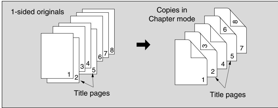
1. Touch APPLICATION on the Basic Screen.

Please Be Reminded!
When starting a new copying job, be sure to close the RADF securely, then press [AUTO RESET].
2. Touch Chapter on the Application Selection Screen.
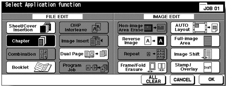
The Chapter Insertion Setting No. Screen will be displayed.
3. Use the control panel keypad to enter the page number of each title page.
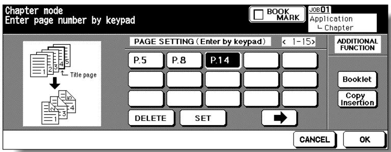
Touch SET after each entry to move to the next key.
When setting more than 15 locations, touch the arrow key to move to the next page.
To clear an incorrect entry, touch DELETE. The entered number will be deleted.

FOR DETAILS
- Entering "0" or the same page number twice will be ignored on the screen.
- Chapter insertions occur in sequence even if original page numbers are entered out of sequence.
- When a page number is larger than the total original page count, insertion occurs as the last page of the document.

OPTION
Touch Booklet on the Chapter Insertion Setting No. Screen to use this function.
To change the selection of paper tray for copying title pages, touch Copy Insertion on the screen. In this case, you can touch CHANGE OF THE INSERTION TRAY to change the currently selected paper tray displayed on the screen.
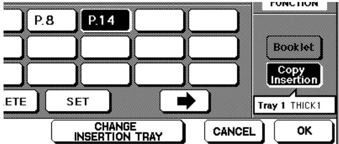
4. When all entries are made, touch OK.
The Application Selection Screen will be restored.
5. Touch OK on the Application Selection Screen.
The Basic Screen will be restored.
6. Enter the desired print quantity from the control panel keypad.

HINT
See p. 3-6 for details on setting print quantity.
7. Position originals FACE UP in the document feeder.

HINTS
- For details on positioning originals, see p. 3-2 to p. 3-4.
- Use RADF store mode (p. 3-33 to p. 3-34) when the original count exceeds 100.
8. Press [START].
![KONICA MINOLTA 7255 - Press [START]. - 1](/content/2025/01/139764/images/1637e644af33bd6f86d55444949a28939205f9e3380df47484740fbc6030fd84.jpg)
CAUTION
When the finisher / shift tray / paper exit tray capacity is exceeded due to the print quantity selected, remove the copied sets as they exit; otherwise, mishandled paper will occur.
Lay Out Several Pages onto One Sheet (Combination)
Use this function to lay out and copy a fixed number (2, 4, or 8) of pages onto one sheet of copy paper (2 in 1, 4 in 1, or 8 in 1).
Specifications for Combination<<
Use RADF.
□AMS is automatically selected. (Normally the fixed size of Tray 1 will be selected.)
Incompatible Conditions: APS, Group, Rotation Sort, Rotation Group, Mixed Original, Sheet/Cover Insertion, Chapter, Booklet, OHP Interleave, Image Insert, Dual page, Program Job, Non-Image Area Erase, Repeat, Storing image in Overlay Memory
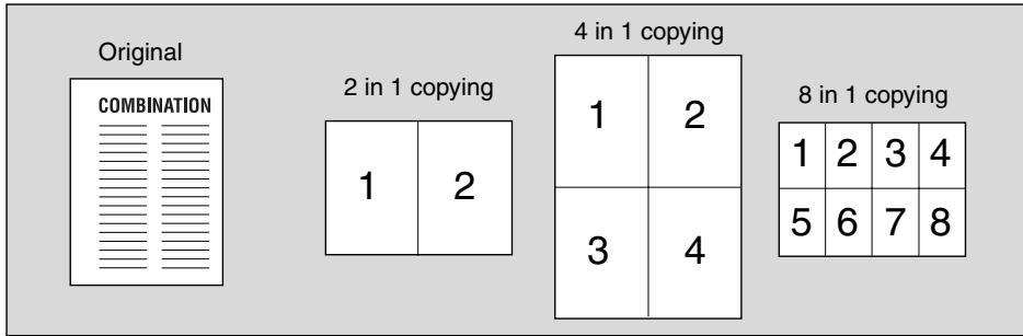
1. Touch APPLICATION on the Basic Screen.

Please Be Reminded!
When starting a new copying job, be sure to close the RADF securely, then press [AUTO RESET].
2. Touch Combination on the Application Selection Screen.
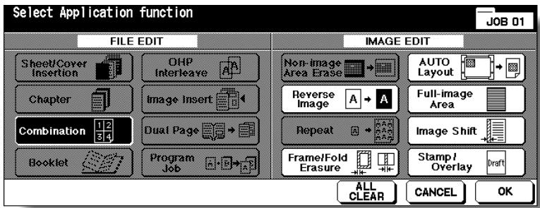
The Combination Mode Selection Screen will be displayed.
3. Select the desired Combination mode.
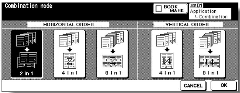
Touch 2 in 1, 4 in 1 or 8 in 1 in the desired order area, referring to the illustration on the following page.
4. Touch OK.
The Application Selection Screen will be restored.
5. Touch OK on the Application Selection Screen.
The Basic Screen will be restored.
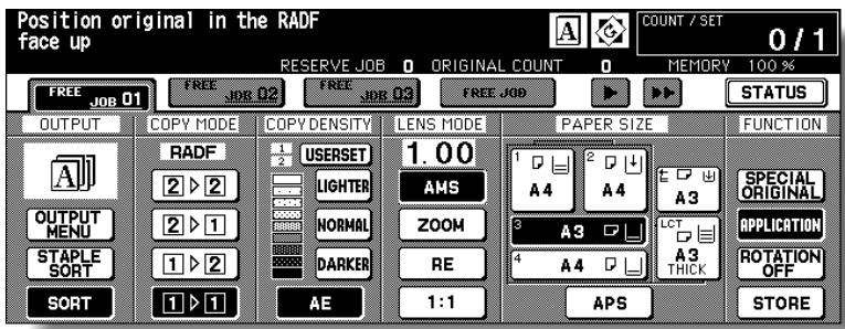
AMS is automatically selected. When selecting any tray other than the one that is set and displayed on the Basic Screen, touch the desired tray key.
6. Select the desired original direction.

Touch SPECIAL ORIGINAL on the Basic Screen to display the Special Original popup menu. Touch to select the desired original direction, then touch OK to return to the Basic Screen.
7. Enter the desired print quantity from the control panel keypad.

HINT
See p. 3-6 for details on setting print quantity.
8. Position originals FACE UP in the document feeder.

HINTS
- For details on positioning originals, see p. 3-2 to p. 3-4.
- Use RADF store mode (p. 3-33 to p. 3-34) when the original count exceeds 100.
9. Press [START].
![KONICA MINOLTA 7255 - Press [START]. - 1](/content/2025/01/139764/images/06d1d0a3d8cd1137e57e1ce3b82c30221871dc6d72e12b8f93190af9c8535627.jpg)
CAUTION
When the finisher / shift tray / paper exit tray capacity is exceeded due to the print quantity selected, remove the copied sets as they exit; otherwise, mishandled paper will occur.
![KONICA MINOLTA 7255 - Press [START]. - 2](/content/2025/01/139764/images/f72f6a35d04176b708b4454e15effb9996e46c5a481a454be05cec9fdda16775.jpg)
FOR DETAILS: Original Type and Layout Order
Refer to the table below to select the desired Combination mode.
| Layout Original | Horizontal order | Vertical order | ||||||||
| 2 in 1 | 4 in 1 | 8 in 1 | 4 in 1 | 8 in 1 | ||||||
| Portrait type COMBINATION | 1 | 2 | 1 | 2 | 1 | 2 | 3 | 4 | 1 | 3 |
| 3 | 4 | 5 | 6 | 7 | 8 | 2 | 4 | |||
| Landscape type COMBINATION | 1 | 1 | 2 | 1 | 2 | 1 | 5 | |||
| 3 | 4 | 3 | 4 | 2 | 6 | |||||
| 5 | 6 | 2 | 7 | |||||||
| 7 | 8 | 4 | 8 | |||||||
Making a Multiple Page Signature Booklet (Booklet)
Use the Booklet to make a multiple page signature booklet on both sides of paper from any tray unless it is specified as Thick or Tab paper of the paper type in the Key Operator mode. Original images are scanned into memory and automatically arranged in booklet format in correct order.
Specifications for Booklet<<
Use RADF.
- Original pages should be a multiple of 4 in 1-2 mode or a multiple of 2 in 2-2 mode; otherwise blank pages are automatically inserted to the last.
AMS is automatically selected. Select the desired paper size.
Original size: A3, B4, A4R, A4, B5R, or B5
□ Incompatible Conditions: APS, 1-1, 2-1, Group, Rotation Sort, Rotation Group, Punch with PK-110 Punching kit (when selecting Cover Sheet mode), Face Up, Cover sheet feeder with Cover mode in Booklet, Mixed Original, Tab Paper, Sheet/Cover Insertion, Combination, OHP Interleave, Program Job, Non-Image Area Erase, Repeat, Storing image in Overlay Memory
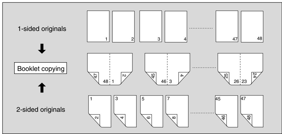
1. Load Copy Paper.
Load A3, B4, A4R, A4, B5R, or B5 copy paper in a tray.
When selecting cover sheet mode (Cover with Copy sheet or Cover with Blank sheet), load the same size paper in any other tray unless it is specified as Thick or Tab paper of the paper type in the Key Operator mode.
2. Touch APPLICATION on the Basic Screen.

Please Be Reminded!
When starting a new copying job, be sure to close the RADF securely, then press [AUTO RESET].
3. Touch Booklet on the Application Selection Screen.
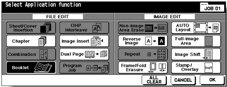
4. Touch to highlight the desired Booklet mode key.
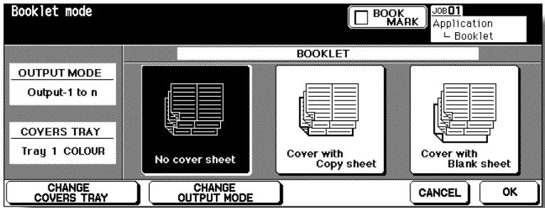
When a cover sheet is required, touch CHANGE COVERS TRAY to select the cover sheet tray source.
Touch CHANGE OUTPUT MODE is you want to change the output order.
5. Touch OK.
The Application Selection Screen will be restored.
Select additional Applications, as desired.

HINT
Key Operator can set the machine to position the page numbers automatically on the outside edges of the copy when using Booklet with Page Numbing in Stamp. See p. 13-39 to p. 13-46.
6. Touch OK on the Application Selection Screen.
The Basic Screen will be restored.
AMS is selected automatically.
7. Select the tray in which you loaded copy paper in step 1.
To release AMS, select the desired magnification, then select paper size.
8. Select the desired copy mode.
Touch 1-2 or 2-2 to specify the desired copy mode.

FOR DETAILS
If the copier is equipped with FS-210 Finisher, Fold or Stitch&Fold output mode is available. Follow the procedure on p. 9-16 to use the function.
9. Enter the desired print quantity from the control panel keypad.

HINT
See p. 3-6 for details on setting print quantity.
10. Position originals FACE UP in the document feeder.

HINTS
- For details on positioning originals, see p. 3-2 to p. 3-4.
- Use RADF store mode (p. 3-33 to p. 3-34) when the original count exceeds 100.

Please Be Reminded!
Original pages should be a multiple of 4 in 1-2 mode or a multiple of 2 in 2-2 mode; otherwise blank pages are automatically inserted to the last.

Please Be Reminded!
When loading originals, heed the following limits on capacity:
Fold mode
12 pages or less for simplex copying
6 pages or less for duplex copying
Stitch&Fold mode
80 pages or less for simplex copying
40 pages or less for duplex copying
Exceeding the above limits on capacity may cause misfeeds in the finisher.
11. Press [START].
![KONICA MINOLTA 7255 - Press [START]. - 1](/content/2025/01/139764/images/dc626021b87a0387a5f5e75ddfd10f2686cbef69fd867595d58389b50bd82092.jpg)
CAUTION
When the finisher / shift tray / paper exit tray capacity is exceeded due to the print quantity selected, remove the copied sets as they exit; otherwise, mishandled paper will occur.
When the Booklet tray capacity is exceeded, the finisher will cease operating. To avoid such trouble, select an appropriate print quantity from the specifications on p. 11-3.
The roller drive unit is located inside the Booklet tray of the finisher. DO NOT put your hand into the roller drive unit when removing folded or stapled & folded sheets; otherwise, you may
be injured.

FOR DETAILS: Selecting Fold / Stitch&Fold Mode
1 Touch OUTPUT MENU on the Basic Screen to display the Output Mode popup menu, then touch MAIN TRAY to highlight it.
2 Touch Stitch&Fold or FOLD, as desired.
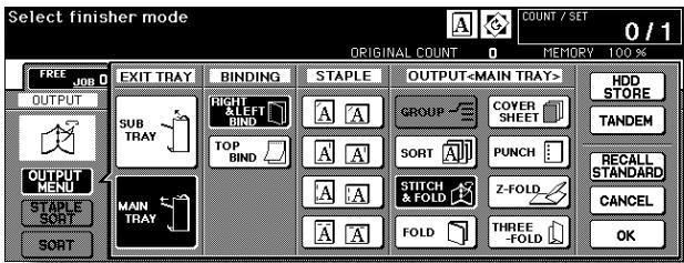
NOTE:
Selecting FOLD or Stitch&Fold will automatically switch the output tray to Booklet tray. Notice that the arrow shown beside the Main tray shifts to the Booklet tray.
3 Touch OK on the Output Mode popup menu. The Basic Screen will be restored with the OUTPUT MENU highlighted.
Copying onto Transparent Films (OHP Interleave)
Use the OHP Interleave function in 1-1 or 2-1 mode to copy onto overhead projection transparent films, and output a blank or copied interleaf sheet with each copied transparent film.
In the Blank sheet interleaving mode, a blank interleaf sheet is output with each transparent film to keep the film material from sticking together.
In the Copy sheet interleaving mode, a copied interleaf sheet is output with each transparent film to provide reference during a presentation; a medium for photocopying; and a set for filing or inserting into a binder.
>>>Specifications for OHP Interleave<<
Transparent film source: Multi-sheet bypass tray
Print quantity: 1
□ Finisher cannot be used.
AMS is automatically selected.
Incompatible Conditions: APS, 1-2, 2-2, Sort, Staple-sort, Group, Rotation Sort, Rotation Group, Fold, Stitch&Fold, Three-Fold, Cover sheet feeding, Punch, Mixed Original, Tab Paper, Sheet/Cover Insertion, Chapter, Combination, Booklet, Image Insert, Program Job, Repeat, Overlay, Storing image in Overlay Memory, Tandem mode
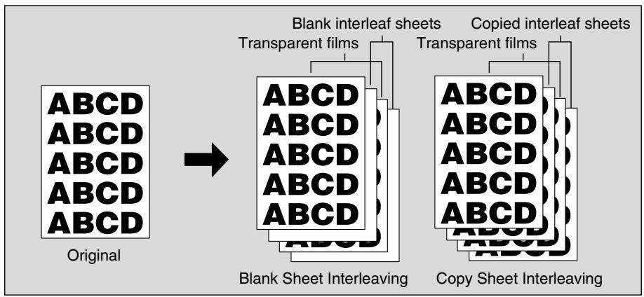
1. Insert a sheet of transparent film into the Multi-sheet bypass tray.

Please Be Reminded!
Do not load transparent films into any other tray.
2. When interleaf sheet is needed, load copy paper in any other tray to match the size of transparent films.
3. Touch APPLICATION on the Basic Screen.

Please Be Reminded!
When starting a new copying job, be sure to close the RADF securely, then press [AUTO RESET].
4. Touch OHP Interleave on the Application Selection Screen.
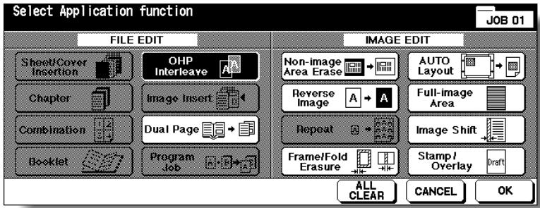
5. Select the desired OHP Interleave mode, then touch OK.
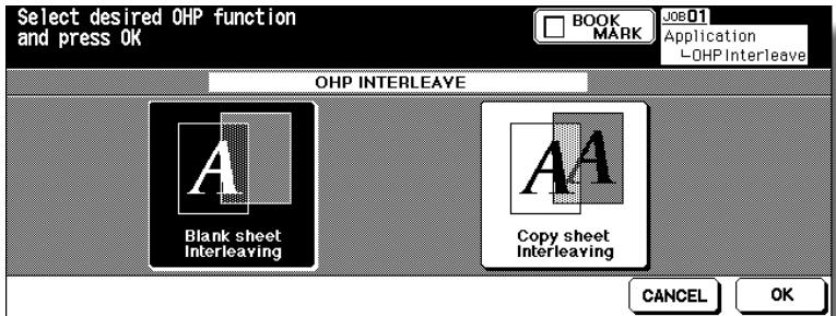
6. Touch OK on the Application Selection Screen.
The Basic Screen will be restored.

FOR DETAILS
AMS is selected automatically.
To release AMS, select the desired magnification.
- Print quantity is already set to 1. You cannot enter any other quantity.
7. Position original(s) FACE UP in the document feeder or FACE DOWN on the platen glass.

HINTS
For details on positioning originals, see p. 3-2 to p. 3-5.
8. Press [START].
Inserting Images into Printed Sets (Image Insert)
Use the Image insert mode to combine images scanned from the platen glass, such as photos, paste-ups, newspaper articles, graphs, etc., with images scanned from the document feeder. Then, output the combined images as a finished set. The selected copy paper size is determined by the size of originals loaded in the document feeder.
Specifications for Image Insert<<
Use RADF and platen glass.
Max. image insert: 30 locations, from p. 1 to p. 999
□Incompatible Conditions: Group, Rotation Sort, Rotation Group, Mixed Original, Tab Paper, Sheet/Cover Insertion, Chapter, Combination, OHP Interleave, Dual Page, Program Job, Non-image Area Erase, Repeat, AUTO Layout, Overlay, Storing image in Overlay Memory
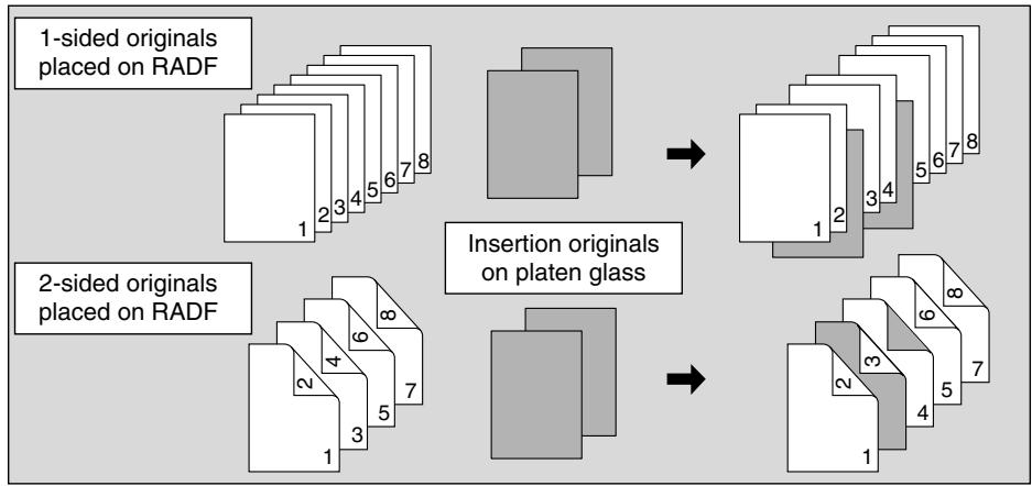
1. Touch APPLICATION on the Basic Screen.

Please Be Reminded!
When starting a new copying job, be sure to close the RADF securely, then press [AUTO RESET].
2. Touch Image Insert on the Application Selection Screen.
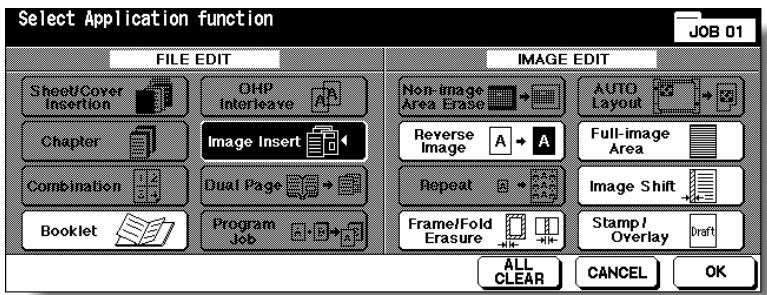
The Image Insertion No. Setting Screen will be displayed.
3. Use the control panel keypad to enter the page number.
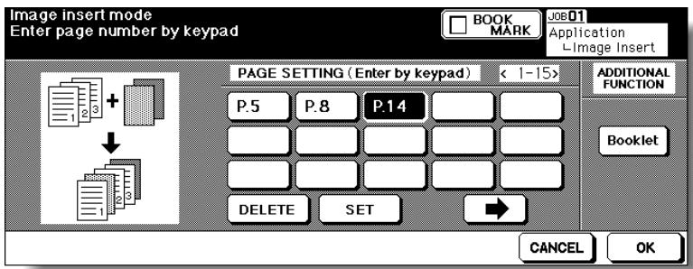
Touch SET after each entry to move to the next key.
When setting more than 15 locations, touch the arrow key to move to the next page.
To clear an incorrect entry, touch DELETE. The entered page number will be deleted.

HINT
See p. 9-21 for detailed example.

OPTION
Touch Booklet on the Image Insertion No. Setting Screen to use this function.
4. When all page number entries are made, touch OK.
The Application Selection Screen will be restored.
5. Touch OK on the Application Selection Screen.
The Basic Screen will be restored.
The STORE key on the Basic Screen appears highlighted to show that the Store mode is automatically selected.
6. Enter the desired print quantity from the control panel keypad.

HINT
See p. 3-6 for details on setting print quantity.
7. Scan the document feeder images: Position originals FACE UP in the document feeder.
If the number of originals exceeds 100, divide them into blocks not exceeding 100 sheets and load them from the block with the first page.
8. Press [START].
The originals positioned in the document feeder will be scanned into memory.
9. Scan the platen glass images.
Open the document feeder.
Position an original FACE DOWN on the platen glass, then close the document feeder.

Please Be Reminded!
PLACE AND SCAN THE ORIGINALS ACCORDING TO PAGINATION.
10. Press [START].
11. Repeat steps 9 and 10 for all originals.

HINTS
- Memory overflow may occur during scanning. See p. 5-11 to p. 5-12.
- Should memory overflow occur frequently, it is recommended that you contact your service representative to extend the memory capacity in your machine.
12. Touch STORE to exit the Store mode.
13. Press [START].
The copier will start printing when ready for output.
![KONICA MINOLTA 7255 - Press [START]. - 1](/content/2025/01/139764/images/0b729d6632e600ee92a4728144759310c5d369a4cbc9eb8dc75dbbe94ad63cfd.jpg)
CAUTION
When the finisher / shift tray / paper exit tray capacity is exceeded due to the print quantity selected, remove the copied sets as they exit; otherwise, mishandled paper will occur.

FOR DETAILS: Entering Page Numbers
For example, if insertion locations are [2/2/6], scanned platen images will be inserted as follows:
The first scanned platen image will be inserted after page 2.
The second scanned platen image will be inserted directly after the first scanned Image insertion.
The third scanned platen image will be inserted after page 6.
NOTES:
- When a page number is larger than the total original count, a sheet is inserted as the last page.
- Insertions occur in sequence, even if page numbers are entered out of sequence.
- Entering the same page number twice will insert two sheets at that location.
Dividing an Image into Right and Left Pages (Dual Page)
The Dual Page mode performs image division on the original image. Use this function to copy an open book or a A3/B4 size sheet onto two A4/B5 sheets in 1-1 or 2-1 mode, or onto the front and back sides of one A4/B5 sheet in 1-2 or 2-2 mode.
The following three modes can be selected from the Dual Page Screen.
- Facing Pages mode: Image division starts from the first scan.
- Front Cover+Facing Pages mode: Image division starts from the second scan, after the first scan copies normally.
- Front/Back Cover+Facing Pages mode: Image division starts from the third scan, after the first and second scan copy normally.
Specifications for Dual Page<<
Store mode is automatically selected.
Paper size: A4, B5
□ Incompatible Conditions: APS, AMS, Rotation Sort, Rotation Group, Fold, Stitch&Fold without Booklet selected, Three-Fold, Mixed Original, Tab Paper, Sheet/Cover Insertion, Combination, Image Insert, Program Job, Repeat, Reduce & Shift in Image Shift, Overlay, Storing image in Overlay Memory
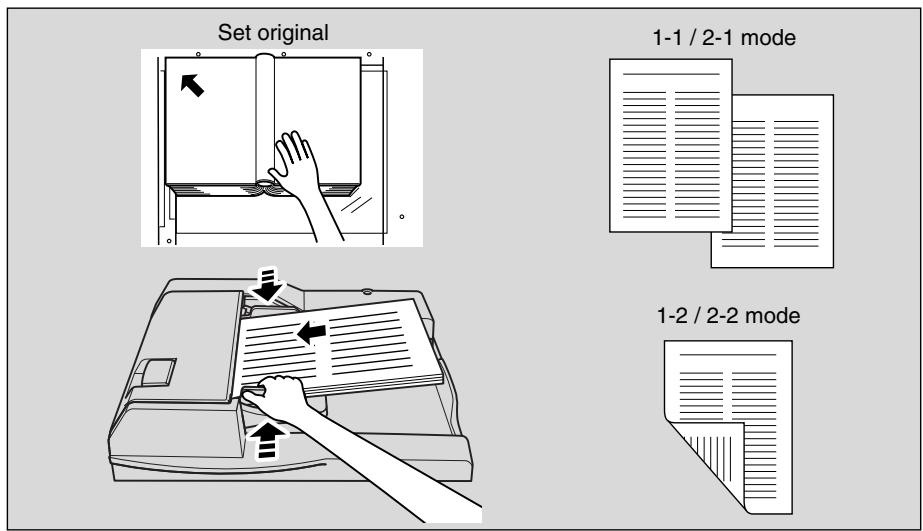
1. Touch APPLICATION on the Basic Screen.

Please Be Reminded!
When starting a new copying job, be sure to close the RADF securely, then press [AUTO RESET].
2. Touch Dual Page on the Application Selection Screen.
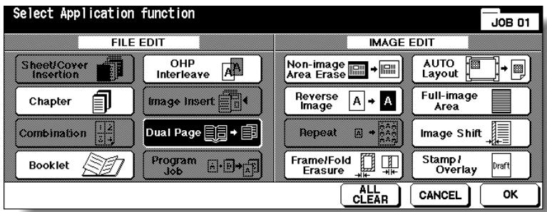
The Dual Page Screen will be displayed.
3. Select the desired Dual Page mode.
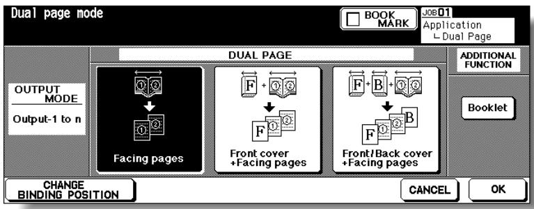
Touch to highlight the desired mode key.
4. Touch CHANGE BINDING POSITION to select the output order according to the original pagination.

OPTION
Touch Booklet on the Dual Page Screen to use this function.
5. Touch OK.
The Application Selection Screen will be restored.
6. Touch OK on the Application Selection Screen.
The Basic Screen will be restored.
APS and AMS are automatically released, and the STORE key appears highlighted to show that the Store mode is automatically selected.
7. Select the desired copy mode, magnification, and paper size.

FOR DETAILS
Available paper size is A4 or B5.
- When selecting Facing pages mode and scanning from the platen glass, select 1-1 or 1-2 copy mode.
- APS and AMS are released and 1.00 magnification is selected automatically. Change the magnification manually, if desired.
8. Enter the desired print quantity from the control panel keypad.

HINT
See p. 3-6 for details on setting print quantity.
9. Position original(s).
When using platen glass to scan, position the first page FACE DOWN with document feeder kept open.
When using document feeder, position original(s) FACE UP.
For details on scanning originals in Front cover + Facing pages and Front/ Back Cover + Facing pages mode, see the description on the following page.
10. Press [START] to scan.
11. Repeat steps 9 and 10 for all originals.

Please Be Reminded!
When using platen glass, Non-Image Area Erase and AUTO Layout are automatically selected.
DO NOT CLOSE the document feeder throughout the scanning job.
12. Touch STORE to exit the Store mode.
13. Press [START].
The copier will start printing when ready for output.
![KONICA MINOLTA 7255 - Press [START]. - 1](/content/2025/01/139764/images/9436361466f782f251bf9cfd798cb5ab51744754a200fb3eca107c7b7546a1f4.jpg)
CAUTION
When the finisher / shift tray / paper exit tray capacity is exceeded due to the print quantity selected, remove the copied sets as they exit; otherwise, mishandled paper will occur.

Scanning Original for Cover
Use platen glass for scanning original for cover.
1 Open the document feeder.
2 Position original for front cover FACE DOWN on the platen glass.
3 Press [START] to start scanning.
4 When Front/Back Cover + Facing pages is selected, scan original for back cover according to the above steps 2 and 3.
5 Use platen glass or document feeder, as required, for scanning body text originals.
To output the set in the same order as the originals, start scanning from the first page.
6 Press [START] to start scanning.
7 Repeat steps 5 and 6 for subsequent originals.
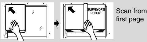
Front cover + Facing pages
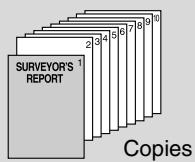
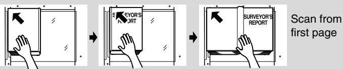
Front/Back cover + Facing pages
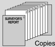
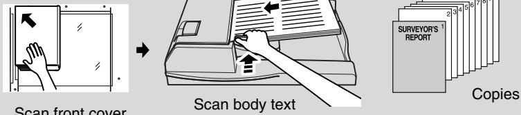
Front cover + Facing pages
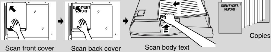
Front/Back cover + Facing pages
NOTES:
- Memory overflow may occur during scanning. See p. 5-11 to p. 5-12.
- When using platen glass, Non-Image Area Erase and AUTO Layout are automatically selected. DO NOT CLOSE the document feeder throughout the scanning job.
Programming Different Settings for an Output Job (Program Job)
In the ordinary Store mode, the combined features selected for the job are applied to all originals to be scanned. In the Program Job mode, you may scan multiple sets of originals and apply different settings on each set (referred to as JOB), then output them all as a complete set.
>>>Specifications for Program Job<<
Max. 100 JOBs can be programmed for an output job.
Once specified, paper size and the paper type/size setting for Multi-sheet bypass tray cannot be changed for another JOB.
- Output mode and print quantity setting cannot be specified for each JOB. The last setting made will be applied to all JOBs.
□ Program Job settings cannot be stored in Job Memory.
□ Incompatible Conditions: APS, Change paper size, Rotation, Group, Rotation Sort, Rotation Group, Fold, Stitch&Fold, Punch with PK-110 Punching kit, Three-Fold, Server function except Image Store & Output mode, Mixed Original, Sheet/Cover Insertion, Chapter, Combination, Booklet, OHP Interleave, Image Insert, Dual Page, 2/4/8 Repeat in Repeat, Overlay, Storing image in Overlay Memory
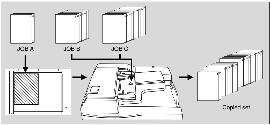
1. Touch APPLICATION on the Basic Screen.

Please Be Reminded!
When starting a new copying job, be sure to close the RADF securely, then press [AUTO RESET].
2. Touch Program Job on the Application Selection Screen.
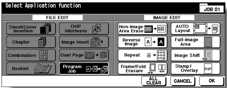
The incompatible function keys will be dimmed to show inactivity.
3. Touch OK on the Application Selection Screen.
The Basic Screen will be restored.
The STORE key on the Basic Screen appears highlighted to show that the Store mode is automatically selected.
4. Select the desired copy conditions.
5. Position originals FACE UP in the document feeder or FACE DOWN on the platen glass.
If the number of document feeder originals exceeds 100, divide them into blocks not exceeding 100 sheets and load them from the block with the first page.
6. Press [START].
The paper size determined at this time will be applied to all subsequent JOBs. When scanning for the current JOB is completed, the popup menu will be displayed in the Basic Screen.
7. Touch CONFIRM.
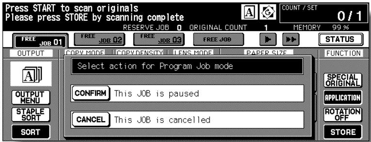
The current JOB images will be stored. To delete the images, touch CANCEL.
8. Repeat steps 4 to 7 until all JOB originals are scanned.

Please Be Reminded!
PLACE AND SCAN EACH ORIGINAL SET IN THE CORRECT ORDER OF PAGINATION.

HINTS
- Memory overflow may occur during scanning. See p. 5-11 to p. 5-12.
- Should memory overflow occur frequently, it is recommended that you contact your service representative to extend the memory capacity in your machine.
9. Select the desired output mode and enter the print quantity from the control panel keypad.

HINT
See p. 3-6 for details on setting print quantity.
10. Touch STORE to exit the Store mode.
11. Press [START].
![KONICA MINOLTA 7255 - Press [START]. - 1](/content/2025/01/139764/images/5a6d2045577b53b4090c32fd5fefd3f7b4f428c4bacf5c5dbd8d383aa5e3d2db.jpg)
CAUTION
When the finisher / shift tray / paper exit tray capacity is exceeded due to the print quantity selected, remove the copied sets as they exit; otherwise, mishandled paper will occur.
Erasing Outside of the Original (Non-Image Area Erase)
The Non-image area erase mode is used to copy non standard or special originals, such as books, magazines, paste-ups, graphs, thick or thin materials, etc. from the platen glass. The exposed glass area outside the borders of the original will not be copied.
>>>Specifications for Non-Image Area Erase<<
Use the platen glass only. Keep RADF open throughout the procedure.
□ Incompatible Conditions: Using RADF, 2-2, 2-1, APS, AMS, Rotation, Rotation Sort, Rotation Group, Mixed Original, Z-Folded Original, Sheet/Cover Insertion, Chapter, Combination, Booklet, Image Insert, Dual Page in RADF Store mode, Reverse Image, Full-Image Area, Reduce & Shift in Image Shift, Storing image in Overlay Memory
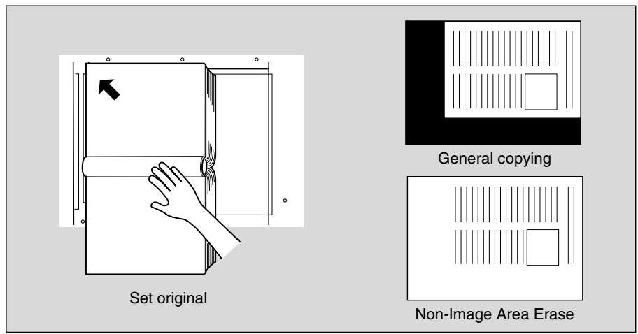
1. Touch APPLICATION on the Basic Screen.

Please Be Reminded!
When starting a new copying job, be sure to close the RADF securely, then press [AUTO RESET].
2. Touch Non-image Area Erase on the Application Selection Screen.
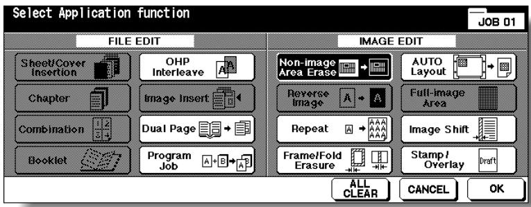
The incompatible function keys will be dimmed to show inactivity.
3. Touch OK on the Application Selection Screen.
The Basic Screen will be restored.
4. Select magnification and paper size, as desired.

FOR DETAILS
- APS and AMS are automatically released.
- Copy mode is automatically set to 1-1. When selecting 1-2 mode, Platen store mode will function automatically.
5. Enter the desired print quantity from the control panel keypad.

HINT
See p. 3-6 for details on setting print quantity.
6. Position original FACE DOWN on the platen glass.

Please Be Reminded!
DO NOT CLOSE THE DOCUMENT FEEDER.
Original size should be larger than 10mm× 10mm
7. Press [START].
![KONICA MINOLTA 7255 - Press [START]. - 1](/content/2025/01/139764/images/12356e9308a8cdd97a17f294cbb88ba2ccf9369b9f990bf338f4ecea02857be7.jpg)
FOR DETAILS: Oblique Erase and Rectangle Erase Modes
The Non-image area erase has two modes; Rectangle erase mode and Oblique erase mode. The copier is initially set to select either mode appropriate for the original placed on the platen glass (AUTO mode). Key Operator can specify either mode and the original density level manually so that the Non-Image Area Erase functions without fail. See p. 13-56.

Oblique erase mode
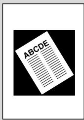
Rectangle erase mode
Having Any Problem?
This function may perform incorrectly if the lighting in the work place is directly over the platen glass. In this case, consult your service representative about an appropriate place for installation.
Reversing Colour in Black and White Image (Reverse Image)
Use Reverse image to reverse the image from black-on-white to white-on-black, and vice versa. This is very good for copying white-on-black originals and reversing them ready to fax.
Specifications for Reverse Image<<
□Incompatible Conditions: Fold, Stitch&Fold, Three-Fold, Non-Image Area Erase, Repeat, Full-Image Area, Stamp, Overlay
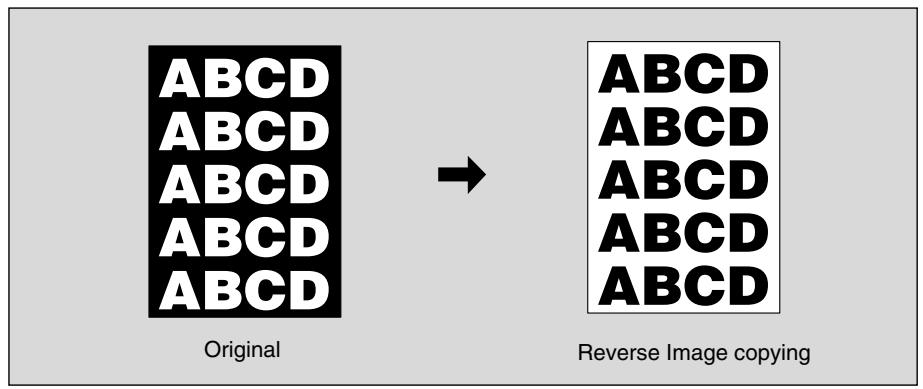
1. Touch APPLICATION on the Basic Screen.

Please Be Reminded!
When starting a new copying job, be sure to close the RADF securely, then press [AUTO RESET].
2. Touch Reverse Image on the Application Selection Screen.
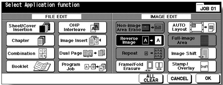
The incompatible function keys will be dimmed to show inactivity.
3. Touch OK on the Application Selection Screen.
The Basic Screen will be restored.
4. Enter the desired print quantity from the control panel keypad.

HINT
See p. 3-6 for details on setting print quantity.
5. Position original(s) FACE UP in the document feeder or FACE DOWN on the platen glass.

HINT
For details on positioning originals, see p. 3-2 to p. 3-5.
6. Press [START].
![KONICA MINOLTA 7255 - Press [START]. - 1](/content/2025/01/139764/images/04053e4b042939cbdcad66a44cc21c49b84bd7817fbfe42ece81c444e61ce10a.jpg)
CAUTION
When the finisher / shift tray / paper exit tray capacity is exceeded due to the print quantity selected, remove the copied sets as they exit; otherwise, mishandled paper will occur.
Repeating Selected Image Area (Repeat: Vert./ Horiz. Mode)
Use this function to repeat the selected image area of 10 mm 150 mm in both vertical and horizontal widths measured from the rear left corner of the A3 original area indicated on the left edge of the platen glass.
>>>Vertical/Horizontal Width Setting Mode Specifications<<
Use the platen glass. (Document feeder cannot be used.)
□Incompatible Conditions: Using RADF, 2-2, 2-1, APS, AMS, Rotation, Group, Rotation Sort, Rotation Group, Mixed Original, Z-Folded Original, Sheet/Cover Insertion, Chapter, Combination, Booklet, OHP Interleave, Image Insert, Dual Page, Non-Image Area Erase, Frame/Fold Erasure, AUTO Layout, Reduce & Shift in Image Shift, Stamp/Overlay
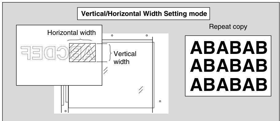
1. Touch APPLICATION on the Basic Screen.

Please Be Reminded!
When starting a new copying job, be sure to close the RADF securely, then press [AUTO RESET].
2. Touch Repeat on the Application Selection Screen.
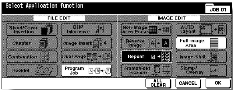
The Repeat Mode Selection Screen will be displayed.
3. Touch Vertical/Horizontal, then specify the vertical and horizontal widths of the scanning area.
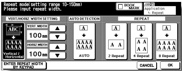
Use up/down arrow key to enter the width from 10 to 150 ~mm in 1 ~mm increments. Keep touching the key to increase/decrease the value continuously.
Or, touch ENTER REPEAT WIDTH BY KEYPAD to display the popup menu to enter the value from the touch screen keypad.
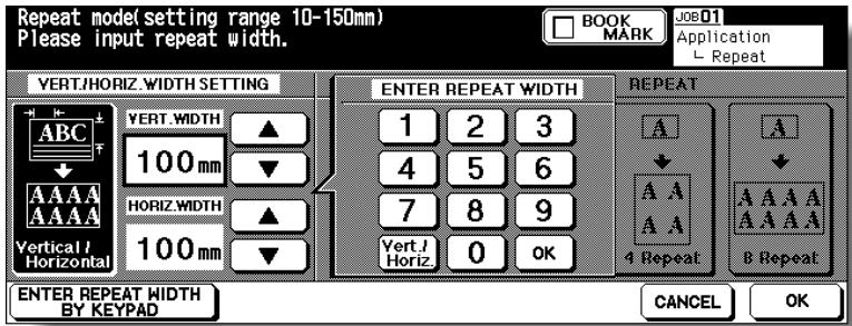
Touch Vert./Horiz. on the popup menu each time to shift it from one to another. Enter the value, then touch OK to restore the Repeat Mode Selection Screen.
4. Touch OK.
The Application Selection Screen will be restored.
5. Touch OK on the Application Selection Screen.
The Basic Screen will be restored.
6. Select the desired magnification and paper size.

FOR DETAILS
- APS and AMS are automatically released, and 1.00 (100%) is selected as a magnification ratio.
- Copy mode is automatically set to 1-1. When selecting 1-2 mode, Platen store mode will function automatically.
7. Enter the desired print quantity from the control panel keypad.

HINT
See p. 3-6 for details on setting print quantity.
8. Position original FACE DOWN on the platen glass.

HINT
See the illustration on p. 9-33 for details.
9. Press [START].
![KONICA MINOLTA 7255 - Press [START]. - 1](/content/2025/01/139764/images/066c9726941ec702ad9f9c27ae0889abb5effd3e1e4062609dd21c69b5855ce9.jpg)
CAUTION
When the finisher / shift tray / paper exit tray capacity is exceeded due to the print quantity selected, remove the copied sets as they exit; otherwise, mishandled paper will occur.
Repeating Automatically Or Selecting Repeating Times(Repeat: AUTO/ Repeat Mode)
Auto Detection mode will automatically set the equal repeat area to the size of the original placed onto the platen glass by activating Non-image area erase. Repeat mode will scan the image area specified by the selected paper size and mode (2 Repeat, 4 Repeat, or 8 Repeat), then arrange the image by specified times in one copy sheet.
>>Auto Detection/ Repeat Mode Specifications<<
□Auto Detection Mode: Use the platen glass. RADF cannot be used.
Repeat Mode Magnification ratio: 1.00 (100%) fixed
□Incompatible Conditions with Auto Detection Mode
Using RADF, 2-2, 2-1, APS, AMS, Rotation, Group, Rotation Sort, Rotation Group, Mixed Original, Z-Folded Original, Sheet/Cover Insertion, Chapter, Combination, Booklet, OHP Interleave, Image Insert, Dual Page, Reverse Image, Frame/Fold Erasure, AUTO Layout, Full-Image Area, Reduce & Shift in Image Shift, Stamp/Overlay
□Incompatible Conditions with Repeat Mode
APS, AMS, Rotation (if magnification is changed from 1.00), Group, Rotation Sort, Rotation Group, Mixed Original, Z-Folded Original, Chapter, Combination, Booklet, OHP Interleave, Image Insert, Dual Page, Non-Image Area Erase, Reverse Image, Frame/Fold Erasure, AUTO Layout, Reduce & Shift in Image Shift, Overlay, Overlay Memory
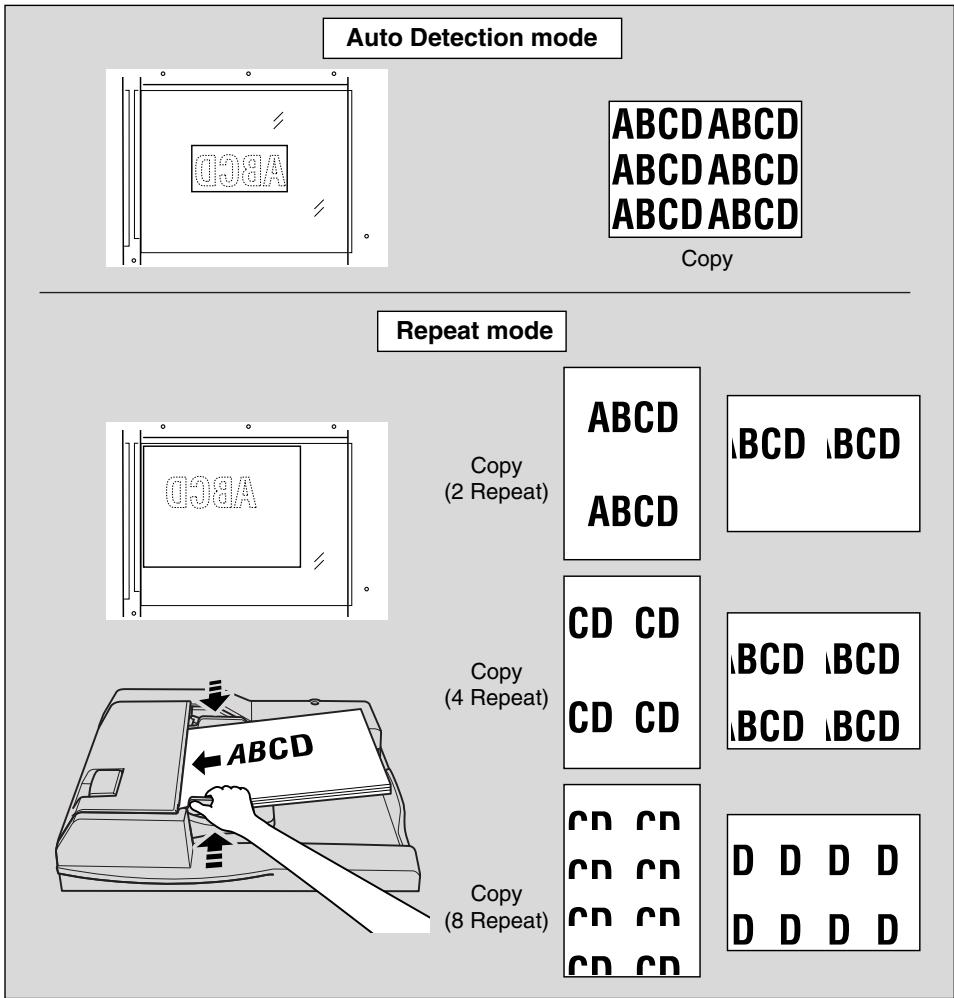
1. Touch APPLICATION on the Basic Screen.

Please Be Reminded!
When starting a new copying job, be sure to close the RADF securely, then press [AUTO RESET].
2. Touch Repeat on the Application Selection Screen.
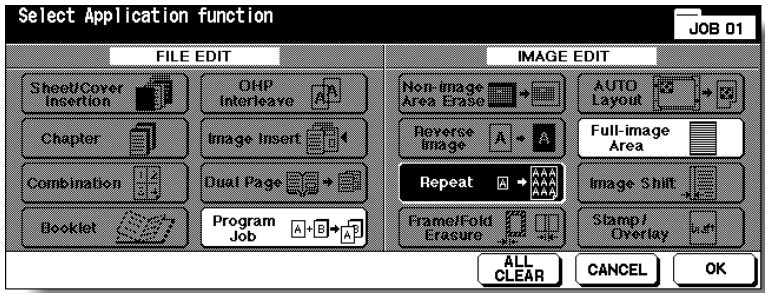
The Repeat Mode Selection Screen will be displayed.
3. Touch to highlight the desired mode key.
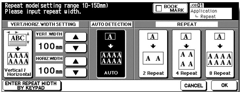
Touch AUTO to select the Auto Detection mode.
Touch 2 Repeat, 4 Repeat, or 8 Repeat to select the desired Repeat mode.
4. Touch OK.
The Application Selection Screen will be restored.

FOR DETAILS
Non-Image Area Erase is automatically selected on the Application Selection Screen when AUTO mode is selected.

HINT
When 2 Repeat mode is selected, Page space function of Image Shift can be used to make the desired amount of blank space between the two images on a page. See p. 9-46 to p. 9-48.
5. Touch OK on the Application Selection Screen.
The Basic Screen will be restored.
6. Select the desired magnification and paper size.

FOR DETAILS
- APS and AMS are automatically released, and 1.00 (100%) is selected as a magnification ratio.
- When 2 Repeat, 4 Repeat, or 8 Repeat is selected, the scanning area will be a portion of the selected paper size equally divided according to the selected mode.
In this case, magnification ratio will be fixed to 1.00 (100%).
- Copy mode is automatically set to 1-1. When selecting 1-2 mode, Platen store mode will function automatically.
7. Enter the desired print quantity from the control panel keypad.

HINT
See p. 3-6 for details on setting print quantity.
8. Position original.
For AUTO mode original, open the document feeder, then position the original FACE DOWN on the platen glass.
For 2 Repeat, 4 Repeat or 8 Repeat mode original, RADF is also available.

HINT
See the illustration on p. 9-36 for details.

Please Be Reminded!
When AUTO mode is selected, Non-Image Area Erase functions automatically.
DO NOT close the document feeder.
9. Press [START].
![KONICA MINOLTA 7255 - Press [START]. - 1](/content/2025/01/139764/images/77a3d991242fee0e682cd906964e6415bdf71123d4d21c8d03e442d75f0edf96.jpg)
CAUTION
When the finisher / shift tray / paper exit tray capacity is exceeded due to the print quantity selected, remove the copied sets as they exit; otherwise, mishandled paper will occur.

FOR DETAILS
The AUTO mode may not operate properly if the lighting in the work place is directly over the platen glass. In this case, consult your service representative about an appropriate place for installation.
Eliminating Black Copy Marks Along Borders (Frame/Fold Erasure)
Use Frame/Fold Erasure to eliminate black copy marks along borders to clean up and improve the presentation of the copy.
Specifications for Frame/Fold Erasure<<
□ Incompatible Conditions: Repeat, Full-Image Area
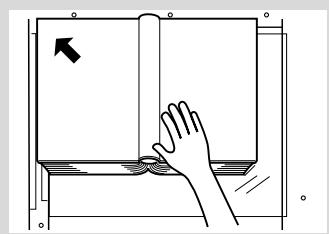
Set original
Frame erasure
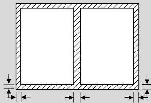
Frame erasure
Folde erasure
Frame erasure

General copying
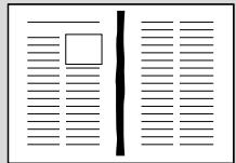
Frame Erasure copying

Fold Erasure copying
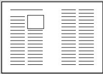
Frame/Fold Erasure copying
1. Touch APPLICATION on the Basic Screen.

Please Be Reminded!
When starting a new copying job, be sure to close the RADF securely, then press [AUTO RESET].
2. Touch Frame/Fold Erasure on the Application Selection Screen.
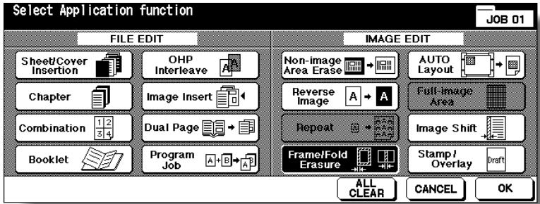
The Frame/Fold Erasure Selection Screen will be displayed.
3. Touch to highlight the desired mode key.
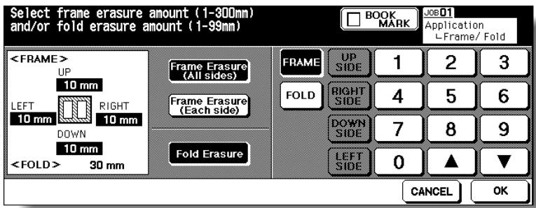
Touch Frame Erasure (All sides), Frame Erasure (Each side), or Fold Erasure to highlight it.
Either Frame erasure mode and Fold erasure can be selected in combination.
4. Specify the erasure amount in the selected mode.
To specify Frame Erasure (All sides) amount:
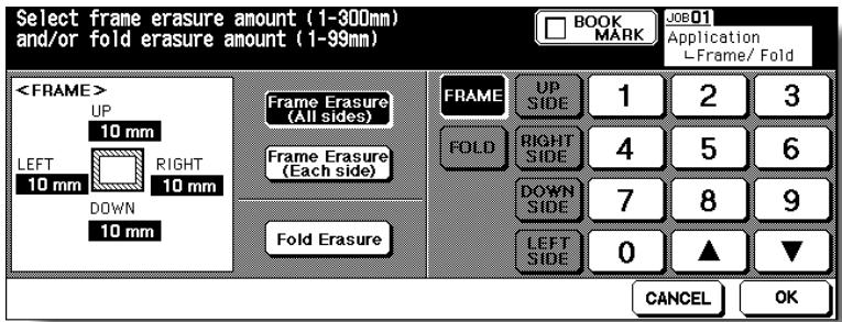
- Touch to highlight FRAME, if not highlighted, then use the touch screen keypad or up/down arrow key to enter the desired erasure amount of the UP, DOWN, LEFT, and RIGHT sides collectively, from 1 to 300mm in 1 mm increments.
To specify Frame Erasure (Each side) amount:
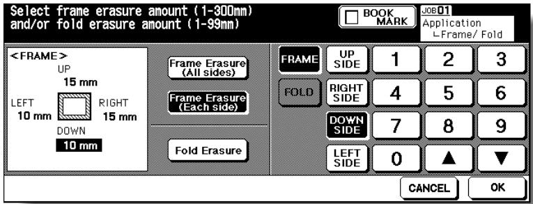
- Touch to highlight FRAME, if not highlighted, then touch UP SIDE, RIGHT SIDE, DOWN SIDE, or LEFT SIDE. The selected side amount will be highlighted in the left illustration area of the screen.
Use the touch screen keypad or up/down arrow key to enter the desired erasure amount, from 1 to 300mm in 1 mm increments.
To specify Fold Erasure amount:
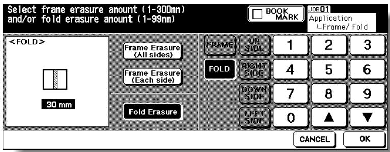
- Touch to highlight FOLD, if not highlighted, then use the touch screen keypad or up/down arrow key to enter the desired erasure amount, from 1 to 99 mm in 1 mm increments.
5. Touch OK.
The Application Selection Screen will be restored.
6. Touch OK on the Application Selection Screen.
The Basic Screen will be restored.
7. Enter the desired print quantity from the control panel keypad.

HINT
See p. 3-6 for details on setting print quantity.
8. Position original(s) FACE UP in the document feeder or FACE DOWN on the platen glass.

HINT
For details on positioning originals, see p. 3-2 to p. 3-5.

FOR DETAILS
When lowering the document feeder onto thick original (e.g. open book), do not press it down too hard. Keep the document feeder open, if required.
9. Press [START].
![KONICA MINOLTA 7255 - Press [START]. - 1](/content/2025/01/139764/images/4560d81e8cf2389152fde51d9c5e047495038f4e46a04dbc21d0aa86d026f693.jpg)
CAUTION
When the finisher / shift tray / paper exit tray capacity is exceeded due to the print quantity selected, remove the copied sets as they exit; otherwise, mishandled paper will occur.
Copying Image in the Centre of Copy Paper (AUTO Layout)
Use this function to detect the image area of the original and centre the whole image on the copy paper making it easy to copy small pieces of paper.
Specifications for AUTO Layout<<
Non-Image Area Erase is automatically selected. Release it manually when using RADF to scan originals.
Incompatible Conditions: 2-2, 2-1, APS, AMS, Rotation, Rotation Sort, Rotation Group, Mixed Original, Z-Folded Original, Sheet/Cover Insertion, Chapter (available when Non-Image Area Erase is released manually), Combination, Booklet, Image Insert, Reverse Image, Repeat, Full-Image Area, Image Shift, Overlay, Storing image in Overlay Memory

1. Touch APPLICATION on the Basic Screen.

Please Be Reminded!
When starting a new copying job, be sure to close the RADF securely, then press [AUTO RESET].
2. Touch AUTO Layout on the Application Selection Screen.
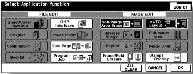
The incompatible function keys will be dimmed to show inactivity.

FOR DETAILS
- Non-Image Area Erase will be selected automatically. When using RADF to scan the original, touch to deselect this function.
- When using Dual Page with this function, the original smaller than the selected paper size will be printed in the centre of the copy paper without image division performed.
3. Touch OK on the Application Selection Screen.
The Basic Screen will be restored.
4. Select the desired magnification and paper size on the Basic Screen.

FOR DETAILS
- APS and AMS are automatically released, and 1.00 (100%) is selected as a magnification ratio.
- Copy mode is automatically set to 1-1. When selecting 1-2 mode, Platen store mode will function automatically.
5. Enter the desired print quantity from the control panel keypad.

HINT
See p. 3-6 for details on setting print quantity.
6. Position original(s) FACE UP in the document feeder or FACE DOWN on the platen glass.

HINT
For details on positioning originals, see p. 3-2 to p. 3-5.

Please Be Reminded!
DO NOT close the RADF when Non-Image Area Erase is selected. Placing original obliquely on the platen glass may cause black copy marks.
7. Press [START].
![KONICA MINOLTA 7255 - Press [START]. - 1](/content/2025/01/139764/images/4715fca6f023a7c28138ab6d1126e29061300c0f6495215052860d2b566c2d09.jpg)
CAUTION
When the finisher / shift tray / paper exit tray capacity is exceeded due to the print quantity selected, remove the copied sets as they exit; otherwise, mishandled paper will occur.

Having Any Problem?
The AUTO layout function may not operate properly if the lighting in the work place is directly over the platen glass. In this case, consult your service representative about an appropriate place for installation.
Use this function to make copies printed completely to the edges.
Specifications for Full-Image Area<<
□ Incompatible Conditions: Rotation Sort, Rotation Group, Non-Image Area Erase, Reverse Image, Frame/Fold Erasure

Original
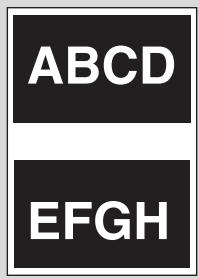
Normal copy

Full-Image Area copy
1. Touch APPLICATION on the Basic Screen.

Please Be Reminded!
When starting a new copying job, be sure to close the RADF securely, then press [AUTO RESET].
2. Touch Full-image Area on the Application Selection Screen.
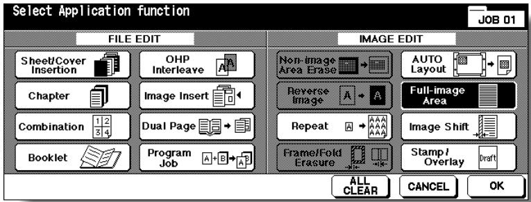
The incompatible function keys will be dimmed to show inactivity.
3. Touch OK on the Application Selection Screen.
The Basic Screen will be restored.
4. Select additional copy conditions, as desired.
5. Enter the desired print quantity from the control panel keypad.

HINT
See p. 3-6 for details on setting print quantity.
6. Position original(s) FACE UP in the document feeder or FACE DOWN on the platen glass.

HINTS
For details on positioning originals, see p. 3-2 to p. 3-5.
7. Press [START].
![KONICA MINOLTA 7255 - Press [START]. - 1](/content/2025/01/139764/images/12b6727eb6e4b561cdd73b8ca125139a475e0e98904b0fe0c9e02371315e30b7.jpg)
CAUTION
When the finisher / shift tray / paper exit tray capacity is exceeded due to the print quantity selected, remove the copied sets as they exit; otherwise, mishandled paper will occur.
Use Image Shift to adjust the position of copy images, e.g. for the purpose of creating a new binding margin on originals to make it easier for filing purposes.
Page Space function is available only when Booklet or 2 Repeat mode of Repeat has been already selected. Use this function to make the desired amount of blank space between the two images on a page. See the illustration on p. 9-48 for details.
If image loss is likely, select the Reduce & Shift mode instead of regular Image shift. See p. 9-49.
Specifications for Image Shift<<
Shift amount: 0 to 250mm in 1 mm increments
Setting in 0.1 mm increments using up/down arrow key is also available by Key Operator setting. See p. 13-39 to 13-46.
□ Incompatible Conditions: AUTO Layout, Storing images in Overlay Memory
- Select the copy mode and paper size from the Basic Screen, as required.
- Touch APPLICATION on the Basic Screen.

Please Be Reminded!
When starting a new copying job, be sure to close the RADF securely, then press [AUTO RESET].
3. Touch Image Shift on the Application Selection Screen.
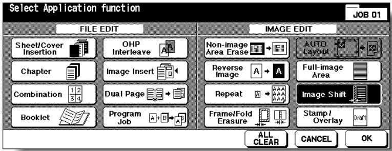
4. Touch Image Shift on the Image Shift Setting Screen, then specify the shift direction and amount.
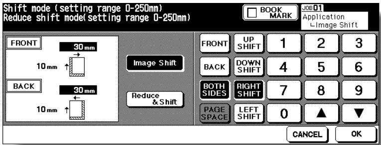
Touch FRONT or BACK to specify the shift direction and amount individually; or BOTH SIDES to specify collectively. The BACK and BOTH SIDES keys function only for duplex copying.
Touch the desired shift direction key to highlight it, then use the touch screen keypad or up/down arrow key to enter the desired shift amount, from 0 mm to 250 mm in 1 mm increments.
The image display on the screen allows you to view the shift direction and amount to be created on the printed sheets.
When Booklet or 2 Repeat mode of Repeat has been already selected, the PAGE SPACE key appears clear on the screen to show its availability.
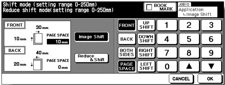
If desired, touch PAGE SPACE to highlight it, then enter the desired amount using the touch screen keypad or up/down arrow key.
5. Touch OK.
The Application Selection Screen will be restored.
6. Touch OK on the Application Selection Screen.
The Basic Screen will be restored.
7. Enter the desired print quantity from the control panel keypad.

HINT
See p. 3-6 for details on setting print quantity.
8. Position original(s) FACE UP in the document feeder or FACE DOWN on the platen glass.

HINT
For details on positioning originals, see p. 3-2 to p. 3-5.
9. Press [START].
![KONICA MINOLTA 7255 - Press [START]. - 1](/content/2025/01/139764/images/f7796c444b20e48319cbee8022eb4e521880fff4fe98a579bbb2a7ccbd1f0973.jpg)
CAUTION
When the finisher / shift tray / paper exit tray capacity is exceeded due to the print quantity selected, remove the copied sets as they exit; otherwise, mishandled paper will occur.

FOR DETAILS: Page Space Function
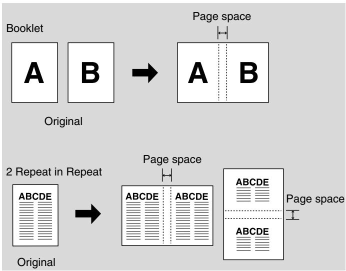
Reducing Images to Create Binding Margin (Reduce&Shift)
Use Reduce & Shift instead of regular Image Shift to prevent image loss when creating a binding margin.
Specifications for Reduce & Shift<<
AMS is automatically selected and cannot be released.
Shift amount: 0 to 250mm in 1 mm increments
Setting in 0.1 mm increments using up/down arrow key is also available by Key Operator setting. See p. 13-39 to 13-46.
Incompatible Conditions: Change magnification, V/H zoom, APS, Mixed Original, Dual Page, Non-Image Area Erase, Repeat, AUTO Layout, Overlay, Storing image in Overlay Memory
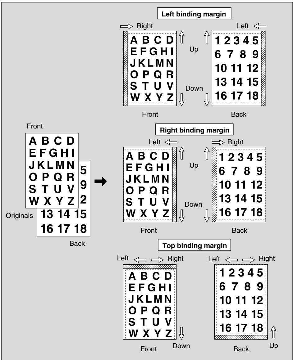
- Select the copy mode and paper size, as required.
- Touch APPLICATION on the Basic Screen.

Please Be Reminded!
When starting a new copying job, be sure to close the RADF securely, then press [AUTO RESET].
- Touch Image Shift on the Application Selection Screen.
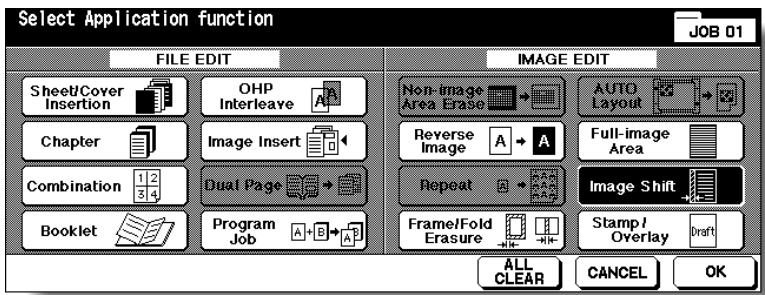
- Touch Reduce & Shift on the Image Shift Setting Screen, then specify the shift direction and amount.
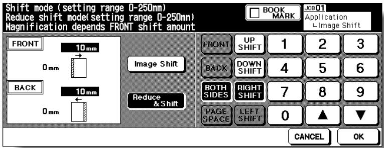
Touch FRONT or BACK. In Reduce & Shift mode, the BOTH SIDES key appears dimmed to show inactivity.
Touch the desired shift direction key to highlight it, then use the touch screen keypad or up/down arrow key to enter the desired shift amount, from 0 mm to 250 mm in 1 mm increments.
The image display on the screen allows you to view the shift direction and amount to be created on the printed sheets.

FOR DETAILS
The AMS will automatically determine the magnification ratio according to the shift amount specified for the front page. The shift amount and magnification ratio determined for the front page will be automatically applied to the back page. If any positioning adjustment is required, touch BACK and make direction and amount change.
5. Touch OK.
The Application Selection Screen will be restored.
6. Touch OK on the Application Selection Screen.
The Basic Screen will be restored.
7. Enter the desired print quantity from the control panel keypad.

HINT
See p. 3-6 for details on setting print quantity.
8. Position original(s) FACE UP in the document feeder or FACE DOWN on the platen glass.

HINT
For details on positioning originals, see p. 3-2 to p. 3-5.
9. Press [START].
![KONICA MINOLTA 7255 - Press [START]. - 1](/content/2025/01/139764/images/785afffc6c79f198971a6785ea38d244dd7f298602290977e50e4707bb057b33.jpg)
CAUTION
When the finisher / shift tray / paper exit tray capacity is exceeded due to the print quantity selected, remove the copied sets as they exit; otherwise, mishandled paper will occur.
This function allows you to print onto output copies the desired type of stamp, page number, numbering, and date/time at the location designated on the screen.
The four stamp types and watermark (described in the next subsection) provided on the Stamp/Overlay Selection Screen can be used individually or in multiple combinations.
>>>Specification for STAMP, SET NUMBERING, PAGE NUMBERING, DATE/TIME<<
To use STAMP, the optional HDD (HD-105) is required to be installed in the machine. Without HDD, this function key will be dimmed to show inactivity.
□ Incompatible Conditions: Reverse Image, Repeat except 2/4/8 Repeat, Overlay (with STAMP and SET NUMBERING), Overlay Memory
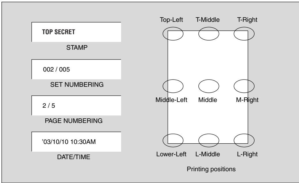
1. Touch APPLICATION on the Basic Screen.

Please Be Reminded!
When starting a new copying job, be sure to close the RADF securely, then press [AUTO RESET].
2. Touch Stamp/Overlay on the Application Selection Screen.
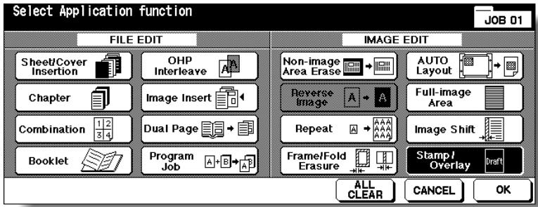
The Stamp/Overlay Selection Screen will be displayed.
3. Touch to select the desired key in the STAMP area.
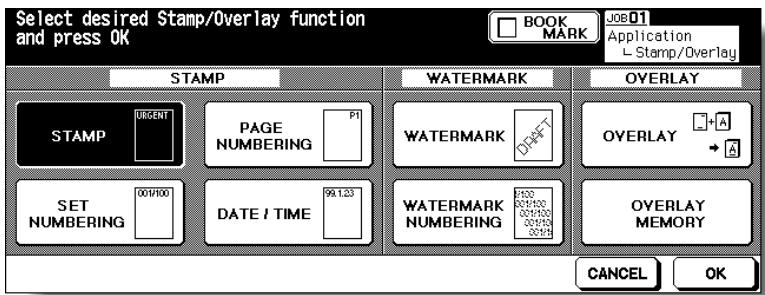
The subsequent screen will be displayed to allow you to specify the selected stamp type.
4. When selecting STAMP: Specify the stamp type, printing position, character size and printed page.
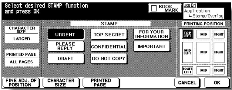
Touch to highlight the desired stamp key and printing position key on the screen. If fine adjustment is required, touch FINE ADJ. OF POSITION to display the Fine Adjustment Setting Screen. See p. 9-56 for details.
Touch CHARACTER SIZE to select LARGER or SMALLER.
Touch PRINTED PAGE to designate whether to print the selected stamp on the cover only or on all pages.
When selecting SET NUMBERING: Specify the numbering type, printing position, character size, printed page and starting No.
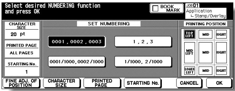
Touch to highlight the desired numbering type key and printing position key on the screen. If fine adjustment is required, touch FINE ADJ. OF POSITION to display the Fine Adjustment Setting Screen. See p. 9-56 for details.
Touch CHARACTER SIZE to select 20 pt or 36 pt.
Touch PRINTED PAGE to designate whether to print the selected stamp on the cover only or on all pages.
Touch STARTING No. to designate the starting number, if required. See p. 9-56 for details.
When selecting PAGE NUMBERING: Specify the page numbering type, printing position, character size, printed page and starting No.
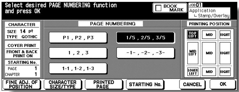
Touch to highlight the desired page numbering type key and printing position key on the screen. If fine adjustment is required, touch FINE ADJ. OF POSI-TION to display the Fine Adjustment Setting Screen. See p. 9-56 for details.
Touch CHARACTER SIZE/TYPE to select the character size (8 pt, 10 pt, 12 pt or 14 pt) and type (GOTHIC or MING). See p. 9-57 for details.
Touch PRINTED PAGE to designate whether to print the selected stamp on the front/back cover or insertions. See p. 9-57 for details.
Touch STARTING No. to designate the starting number, if required. See p. 9-56 for details.
When selecting DATE/TIME: Specify the date/time type, printing position, character size and printed page.
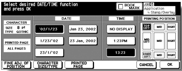
Touch to highlight the desired date, time, and printing position keys on the screen. If fine adjustment is required, touch FINE ADJ. OF POSITION to display the Fine Adjustment Setting Screen. See p. 9-56 for details.
Touch CHARACTER SIZE/TYPE to select the character size (8 pt, 10 pt, 12 pt or 14 pt) and type (GOTHIC or MING). See p. 9-57 for details.
Touch PRINTED PAGE to designate whether to print the selected stamp on the cover only or on all pages.
5. Touch OK.
The Stamp/Overlay Selection Screen will be restored.
Touch to select another stamp function key to use in combination, if desired.
6. Touch OK on the Stamp/Overlay Selection Screen.
The Application Selection Screen will be restored.
7. Touch OK on the Application Selection Screen.
The Basic Screen will be restored.
8. Enter the desired print quantity from the control panel keypad.

HINT
See p. 3-6 for details on setting print quantity.
9. Position original(s) FACE UP in the document feeder or FACE DOWN on the platen glass.

HINT
For details on positioning originals, see p. 3-2 to p. 3-5.
10. Press [START].
![KONICA MINOLTA 7255 - Press [START]. - 1](/content/2025/01/139764/images/c55c9ee8a845220833f773501f72e92972640f577a801703a2a5527d702bcca7.jpg)
CAUTION
When the finisher / shift tray / paper exit tray capacity is exceeded due to the print quantity selected, remove the copied sets as they exit; otherwise, mishandled paper will occur.

FOR DETAILS: Fine Adjustment Setting Screen
When FINE ADJ. OF POSITION is touched, the Fine Adjustment Setting Screen will be displayed.
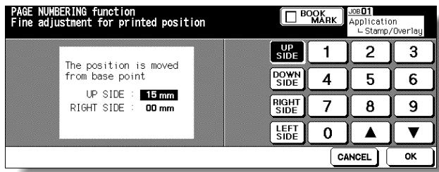
Touch UP SIDE, DOWN SIDE, RIGHT SIDE, or LEFT SIDE to specify the direction, then use the touch screen keypad or up/down arrow key to enter the desired amount, from 0 to 50~mm .
Touch OK to return to the previous screen.
Starting No. Setting Screen: Available from SET NUMBERING or WATERMARK NUMBERING
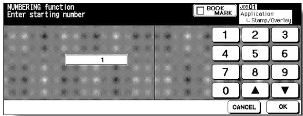
Use the touch screen keypad or up/down arrow key to enter the desired starting number, then touch OK to return to the previous screen.
Starting No. Setting Screen: Available from PAGE NUMBERING
When Chapter is already selected, the chapter starting number can also be specified on the Starting No. Setting Screen.
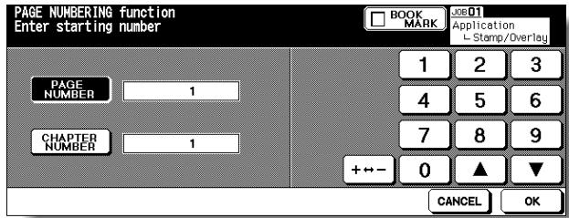
Touch PAGE NUMBER or CHAPTER NUMBER to highlight it, then use the touch screen keypad or up/down arrow key to enter the desired starting number for each.
Use + to enter a minus number to print from halfway through, e.g. -2 to print "1" from page 4.
Touch OK to return to the previous screen.
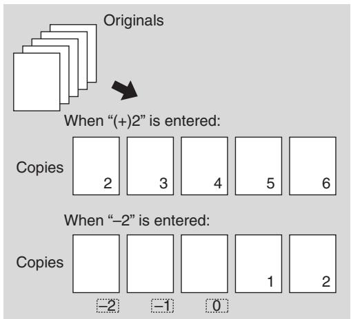
Character Size/Type Selection Screen: from PAGENUMBERING or DATE/TIME When CHARACTER SIZE/TYPE is touched, the Character Size/Type Selection Screen will be displayed.
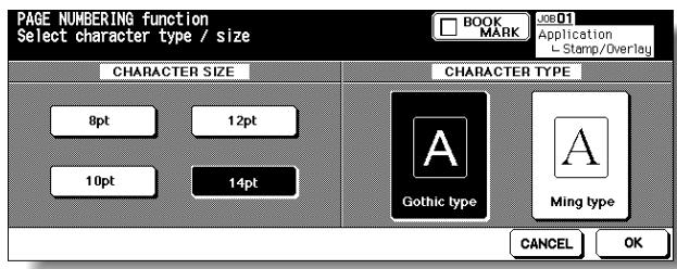
Touch to select the desired key, then touch OK to return to the previous screen.
Cover/Insert Print Setting Selection Screen: from PAGE NUMBERING
When copied/blank insertion mode of Sheet/Cover Insertion has been already selected, this screen allows you to specify whether to print the page number on insertions, or skip them from the page count.
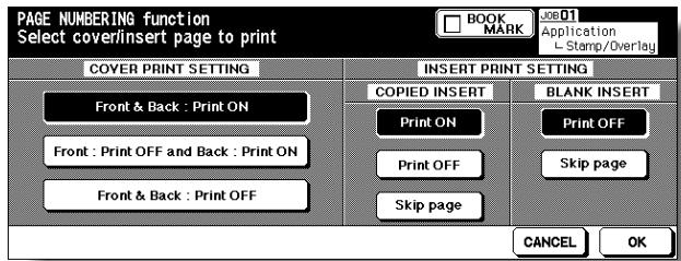
Touch to select the desired key, then touch OK to return to the Page Numbering Type Selection Screen.
Use this function to print the desired letter type obliquely in the centre of the page (WATERMARK), or the numbers in the specified form repeatedly over the scanned image (WATERMARK NUMBERING).
Specification for WATERMARK and WATERMARK NUMBERING<<
To use WATERMARK, the optional HDD (HD-105) is required to be installed in the machine. Without HDD, this function key will be dimmed to show inactivity.
□Incompatible Conditions: Reverse Image, Repeat except 2/4/8 Repeat, Overlay, Overlay Memory
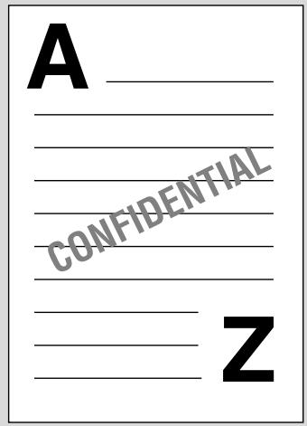
WATERMARK
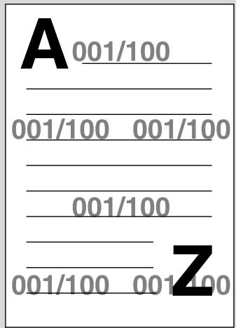
WATERMARK NUMBERING
1. Touch APPLICATION on the Basic Screen.

Please Be Reminded!
When starting a new copying job, be sure to close the RADF securely, then press [AUTO RESET].
2. Touch Stamp/Overlay on the Application Selection Screen.
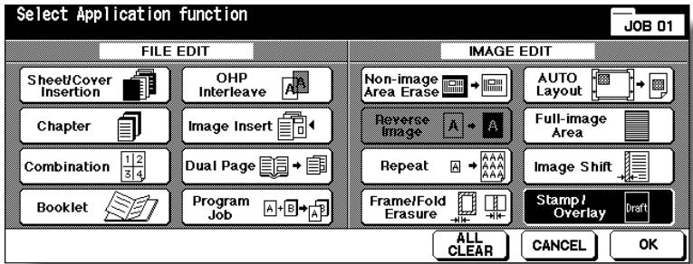
The Stamp/Overlay Selection Screen will be displayed.
3. Touch WATERMARK or WATERMARK NUMBERING, as desired.
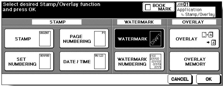
The subsequent screen will be displayed to allow you to specify the selected watermark type.
4. When selecting WATERMARK: Specify the desired watermark type and density.
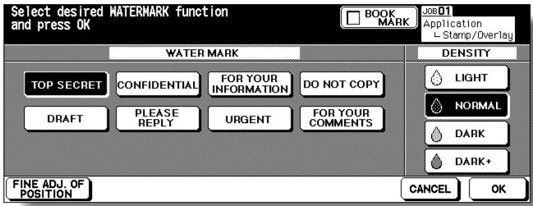
Touch to highlight the desired watermark key and density key on the screen. If fine adjustment of the centred watermark position is required, touch FINE ADJ. OF POSITION to display the Fine Adjustment Setting Screen. See p. 9-56 for details.
When selecting WATERMARK NUMBERING: Specify the desired watermark numbering type, density, character size and starting No.

Touch to highlight the desired watermark key and density key on the screen.
Touch CHARACTER SIZE to select 20 pt or 36 pt.
Touch STARTING No. to designate the starting number, if required. See p. 9-56 for details.
5. Touch OK.
The Stamp/Overlay Selection Screen will be restored.
Touch to select another stamp function key to use in combination, if desired.
6. Touch OK on the Stamp/Overlay Selection Screen.
The Application Selection Screen will be restored.
7. Touch OK on the Application Selection Screen.
The Basic Screen will be restored.
8. Enter the desired print quantity from the control panel keypad.

HINT
See p. 3-6 for details on setting print quantity.
9. Position original(s) FACE UP in the document feeder or FACE DOWN on the platen glass.

HINT
For details on positioning originals, see p. 3-2 to p. 3-5.
10. Press [START].
![KONICA MINOLTA 7255 - Press [START]. - 1](/content/2025/01/139764/images/1e3ee5cac01cd67d54d056957d9c78f35c57d8cb394fd4cdaead1405927ec2c2.jpg)
CAUTION
When the finisher / shift tray / paper exit tray capacity is exceeded due to the print quantity selected, remove the copied sets as they exit; otherwise, mishandled paper will occur.
Overlaying an Image onto Each Page Copied in the Job (Overlay)
Use this function to scan an image, then overlay the image onto each page copied in the job.
Specification for Overlay<<
Store mode is automatically selected.
Incompatible Conditions: Rotation, Rotation Sort, Rotation Group, Mixed Original, Sheet/Cover Insertion, Combination, OHP Interleave, Image Insert, Dual page, Program Job, Repeat, AUTO Layout, Reduce & Shift in Image Shift, STAMP, SET NUMBERING, WATERMARK, WATERMARK NUMBERING
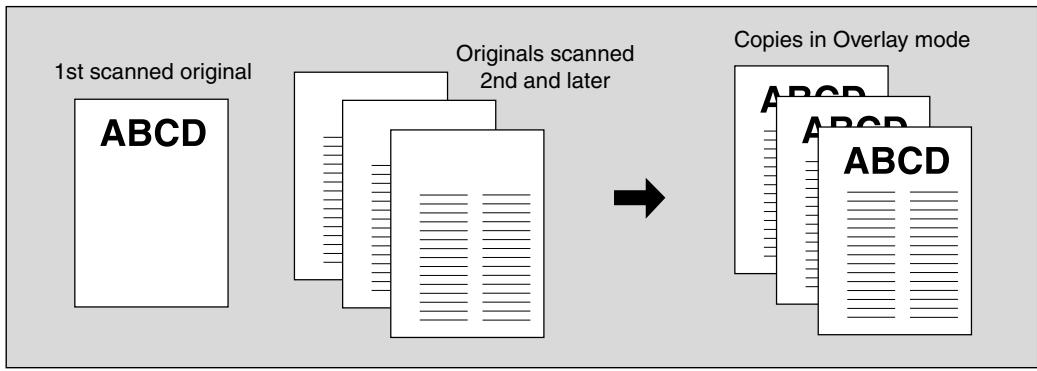
1. Touch APPLICATION on the Basic Screen.

Please Be Reminded!
When starting a new copying job, be sure to close the RADF securely, then press [AUTO RESET].
2. Touch Stamp/Overlay on the Application Selection Screen.
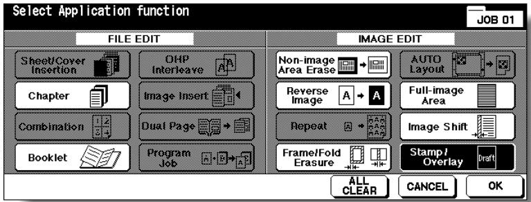
The Stamp/Overlay Selection Screen will be displayed.
3. Touch OVERLAY.
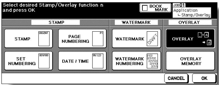
4. Touch OK on the Stamp/Overlay Selection Screen.
The Application Selection Screen will be restored.
5. Touch OK on the Application Selection Screen.
The Basic Screen will be restored.
The Store mode is automatically selected.
6. Select the desired paper size and magnification on the Basic Screen.
APS and AMS are automatically released, and 1.00 (100%) is selected as a magnification ratio.
7. Enter the desired print quantity from the control panel keypad.

HINT
See p. 3-6 for details on setting print quantity.
8. Position the overlaying original.
Position the original FACE UP in the document feeder or FACE DOWN on the platen glass.

HINT
For details on positioning originals, see p. 3-2 to p. 3-5.
9. Press [START] to scan.
The original image will be scanned into memory.
10. Position the original(s) to be overlaid.
Position the original FACE UP in the document feeder or FACE DOWN on the platen glass.
- Press [START] to scan.
- Repeat steps 10 and 11 for all originals.
- Touch STORE to exit the Store mode, then press [START] to print.

CAUTION
When the finisher / shift tray / paper exit tray capacity is exceeded due to the print quantity selected, remove the copied sets as they exit; otherwise, mishandled paper will occur.
Storing an Overlay Image in HDD / Overlaying Image Stored in HDD (Overlay Memory)
Use Overlay Memory to scan and store several images in HDD, then recall the desired image from the HDD to overlay onto each page copied in the job.
>>>Specification for Overlay Memory<<
To use this function, the optional HDD (HD-105) is required to be installed in the machine. Without HDD, this function key will be dimmed to show inactivity.
□ Incompatible Conditions with Image Store: Using RADF, 1-2, 2-2, 2-1, AMS, Rotation, Reserve Mode, Interrupt Mode, Selecting Output Mode, Mixed Original, Z-Folded Original, Tab Paper, Sheet/Cover Insertion, Chapter, Combination, Booklet, OHP Interleave, Image Insert, Dual Page, Program Job, Non-Image Area Erase, Reverse Image, Repeat, AUTO Layout, Image Shift, Stamp, Overlay
□Incompatible Conditions with Output: Reverse Image, STAMP, SET NUMBERING, WATERMARK, WATERMARK NUMBERING in Stamp
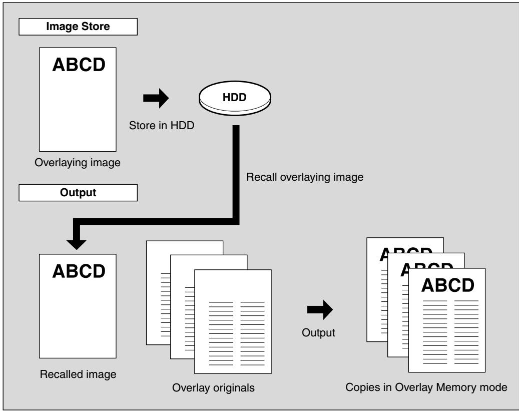
1. Touch APPLICATION on the Basic Screen.

Please Be Reminded!
When starting a new copying job, be sure to close the RADF securely, then press [AUTO RESET].
2. Touch Stamp/Overlay on the Application Selection Screen.
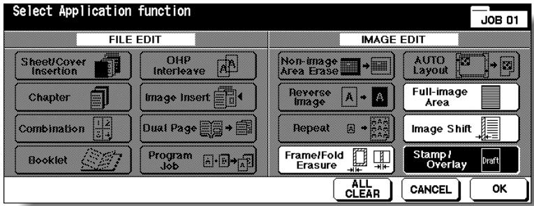
The Stamp/Overlay Selection Screen will be displayed.
3. Touch OVERLAY MEMORY.
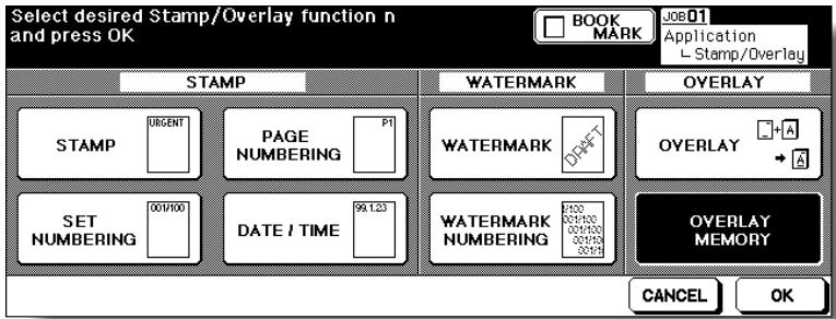
The Overlaying Image Selection Screen will be displayed. Proceed to step 9, when only recalling the stored image.
4. Touch IMAGE STORE to display the Image Name Entry Screen.
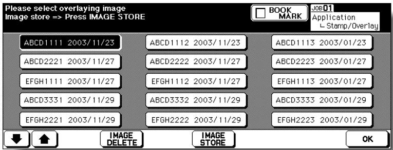
5. Enter the desired image name.
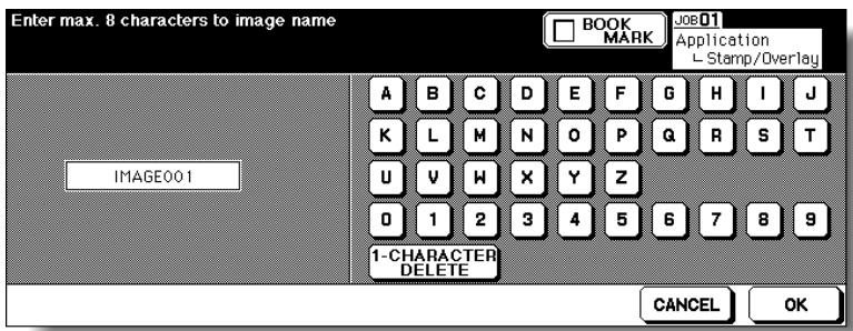
Use the touch screen keypad to enter the desired name up to 8 characters. The date when you made this entry will also be stored automatically.
To correct an entry, touch 1-CHARACTER DELETE repeatedly to delete each character, then enter the correct name.
6. If the image name is correct, touch OK.
The Basic Screen to store the overlaying image will be displayed. Select the desired copy conditions.

HINT
The popup menu may be displayed to prompt you that the entered image name has been already used. See p. 9-68 for details.
7. Position the overlaying original on the platen glass.

FOR DETAILS
The document feeder cannot be used for storing the overlaying image.
8. Press [START] to scan.
The Overlaying Image Data Storing Screen will be displayed.
![KONICA MINOLTA 7255 - Press [START] to scan. - 1](/content/2025/01/139764/images/b0fe6328fed75c809388f0953c067390ca7c8b6a349f6a2424d085b510f258aa.jpg)
![KONICA MINOLTA 7255 - Press [START] to scan. - 2](/content/2025/01/139764/images/295293f878b4b9489da727d6ba0dabbd9305d67e28d029cba7b0443c83c4995d.jpg)
FOR DETAILS
To stop scanning, press [STOP].
The machine automatically starts to store the overlaying image data in the HDD. The Overlaying Image Selection Screen will resume when the storing function is completed.
To continue to store the overlaying image data, return to step 4.
9. Touch to select the desired overlaying image data, then touch OK.

The Stamp/Overlay Selection Screen will be restored.

FOR DETAILS: Image Delete Key on the Overlay Image Selection Screen
If the IMAGE DELETE key is displayed on the Overlay Image Selection Screen, you can delete the stored image and name. Select the image name using up/down arrow key to scroll, then touch IMAGE DELETE.
10. Touch OK to return to the Application Selection Screen.
11. Touch OK to return to the Basic Screen.
The Store mode is automatically selected, and APS and AMS are released. Set the desired conditions on the Basic Screen.
12. Enter the desired print quantity from the control panel keypad.

HINT
See p. 3-6 for details on setting print quantity.
13. Position the original(s) to be overlaid.
Position the original FACE UP in the document feeder or FACE DOWN on the platen glass.
14. Press [START] to scan.
15. Repeat steps 13 and 14 for all originals.
16. Touch STORE to exit the Store mode, then press [START] to print.
![KONICA MINOLTA 7255 - Touch STORE to exit the Store mode, then press [START] to print. - 1](/content/2025/01/139764/images/85dc53615b4e3f36cb848570dc7b3f70b4c9b7f60ff12182241c1beac3abb188.jpg)
CAUTION
When the finisher / shift tray / paper exit tray capacity is exceeded due to the print quantity selected, remove the copied sets as they exit; otherwise, mishandled paper will occur.

FOR DETAILS: Popup Menu for Name Duplication
If the popup menu with YES and NO keys is displayed instead of the Basic Screen, the entered name is duplicated. Touch YES to enter a new name, or NO to create a duplicate name.
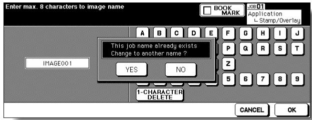
If the popup menu with OK key is displayed, the entered name is duplicated. Touch OK, then enter a new name.
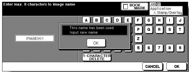
Changing the popup menu for duplicate name and displaying the IMAGE DELETE key is available in the Memory switch No. 41 of the Key Operator setting. See p. 13-39 ~ p. 13-46.
SECTION
10
Network Function
How to Use Server Functions and Web Utilities
To Use Server Functions 10-2
Storing/Deleting Image Data in HDD/PC (Image Store/Delete).....10-4
Storing Image Data While Copying (Image Store&Output) 10-16
Recalling Image Data from HDD/PC (Image Recall) 10-19
Editing Image Data Using PC (Image Edit) 10-23
To Use Web Utilities 10-26
To Display Information on Machine 10-28
To Display Current Machine Status (Job Status) 10-29
Operating Image Data Stored in HDD (HDD Job Information) ....10-31
Setting E-Mail Transmission Function (Environment Setup) 10-35
Setting E.K.C. Function (Environment Setup) 10-37
Setting Scan Transmission Function (Environment Setup) 10-47
Transmitting/Editing Machine Setting File (Environment Setup) ..10-53
Server
Functions
Image
Store/Delete
Image
Store&Output
Image Recall
Image Edit
To Use Web
Utilities
Machine
Information
Job Status
HDD Job
Information
Environment
Setup
10
Netw
Function
Use the Server function with HDD to accumulate scanned images into built-in DIMM (memory), then store the image data in HDD (option) so that the data can be recalled to DIMM and output as needed. This function also allows you to store the image data for normal copying procedures.
Use the Server function with PC to store the image data accumulated in built-in DIMM (memory) in PC, and transmit the image data to PC over a network. The image data can be recalled from PC to DIMM and output as needed. This function also allows you to edit the image data on PC and transmit the edited data to DIMM for printing.
Even when the machine is connected with several PCs over a network, this function can be used with only one PC at a time.

FOR DETAILS
- Installation of the optional HDD (HD-105) is required for the Server function with HDD.
- To use the Server function with PC, a PC must have a specific setup application installed. Two types of the setup application are provided. For detailed information, contact your service representative.
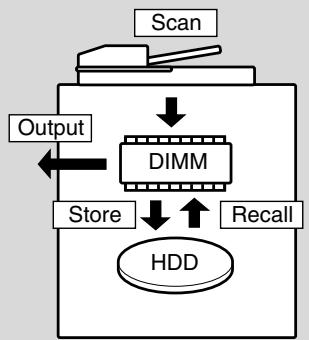
Server Function with HDD

Server Function with PC
The Server function provides the following four modes:
① Image Store/Delete mode
Store the image data scanned from originals in HDD/PC, transmit the data from HDD to PC, or delete the data stored in HDD/PC.
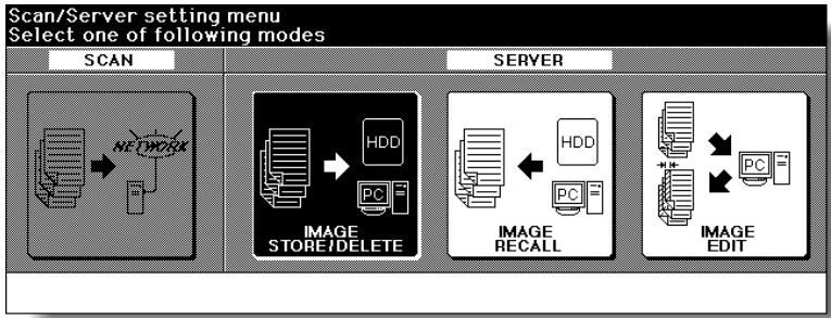
② Image Store & Output mode
Store the scanned image data in HDD after copying is completed.
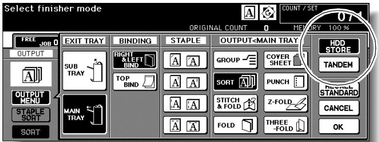
③ Image Recall mode
Recall the image data stored in HDD/PC to built-in DIMM for printing.
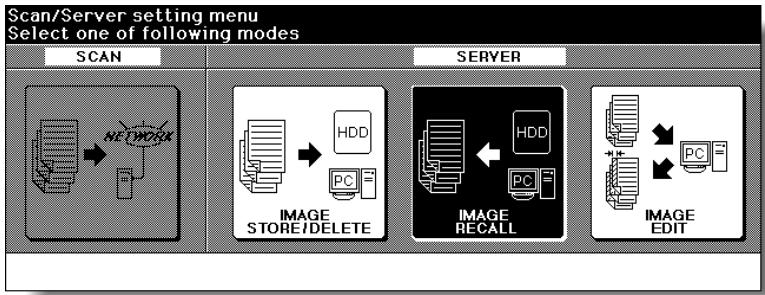
④ Image Edit mode
Edit the image data by PC.
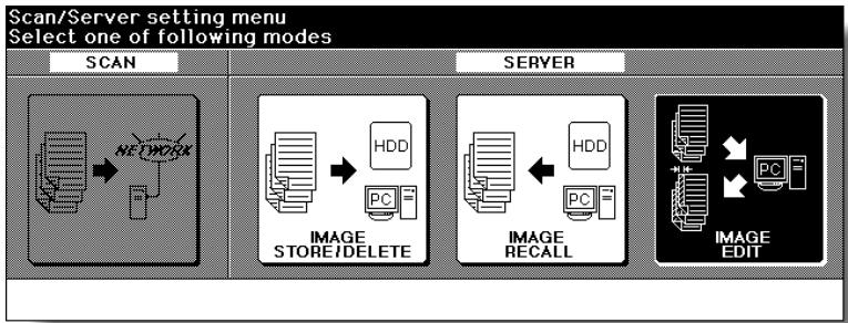
Storing/Deleting Image Data in HDD/PC (Image Store/Delete)
Use this function to store the image data into HDD/PC. In the event data is already stored in HDD/PC, use this function to transmit it from HDD to PC or delete it from HDD/PC.

FOR DETAILS
- Installation of the optional HDD (HD-105) is required for storing data in the HDD.
- To store data in PC, the machine should be connected to PC by cross-cable, or with network provided that a specific software for using Server function is installed in PC.
- The above two conditions should be fulfilled for transmitting data from HDD to PC.
To Store Image Data in HDD/PC
Specify your password when storing the data in HDD/PC for protection. Image data can be given an alphabetical job name.
Specifications for Storing Image Data in HDD/PC<<
□ Incompatible Scanning Conditions: 1-2, 2-2, AMS, Selecting output mode, Selecting paper size (APS is automatically selected), Setting print quantity, Rotation, FULL AREA in Non STD Size, Sheet/Cover Insertion, Chapter, Combination, Booklet, OHP Interleave, Image Insert, Dual Page, Program Job (available in Image Store&Output Mode only), Non-Image Area Erase, Reverse Image, Repeat, AUTO Layout, Image Shift, Stamp/Overlay
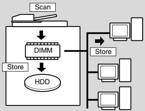
1. Press [MODE] to light up the [SCAN/SERVER] LED.
The Scan/Server Setting Menu Screen will be displayed.
![KONICA MINOLTA 7255 - Press [MODE] to light up the [SCAN/SERVER] LED. - 1](/content/2025/01/139764/images/cd7c55165393a4c47fbfe3fee24dc6a4dc0fb3b5cca106d3f23caddadb662166.jpg)
2. Touch IMAGE STORE/DELETE.
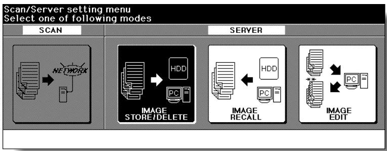
The Image Data Store/Delete Site Selection Screen will be displayed.
3. Touch SCANNER→HDD or SCANNER→PC.
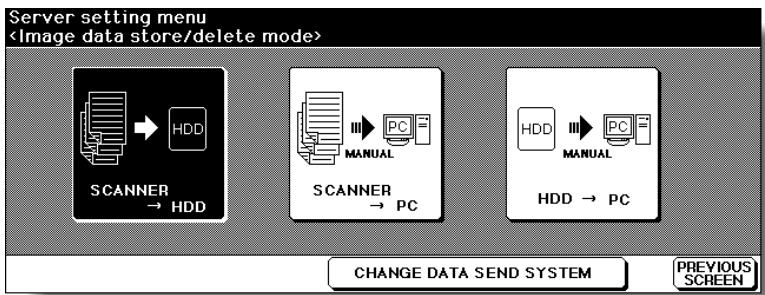
The Image Data Password Entry Screen will be displayed.

HINTS
- To store the image data in PC and to use the CHANGE DATA SEND SYSTEM key on the screen, follow the instruction according to the setup application installed in a PC. For detailed information, refer to the instruction of the setup application.
- The image data stored in HDD can be duplicated in PC using a specific backup tool. Contact your service representative, if desired.
4. Enter the desired image data password in up to 8 characters from the touch screen keypad.

To correct an entry, touch 1-CHARACTER DELETE repeatedly to delete each character, then enter the correct password.
5. If the password is correct, touch OK.
The Job Name Entry Screen will be displayed.
6. Enter the desired job name in up to 8 characters from the touch screen keypad.
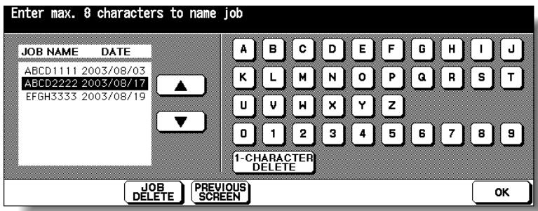
To correct an entry, touch 1-CHARACTER DELETE repeatedly to delete each character, then enter the correct job name.
7. If the job name is correct, touch OK.
The Scanner Setting Screen will be displayed.

FOR DETAILS
If entered job name has already been used, the popup menu appears to ask you whether to rewrite the data or to re-enter new name.
Touch YES to rewrite, or NO to create new name.
8. Select the desired scanning conditions.
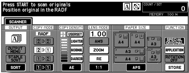

FOR DETAILS
Print quantity cannot be entered.
Store mode is available. Touch STORE to highlight it to use this function.
9. Position original(s) FACE UP in the document feeder or FACE DOWN on the platen glass.

HINT
See p. 3-2 to p. 3-5 for details on positioning originals.
10. Press [START] to scan original(s).
When scanning originals is completed, the machine automatically begins storing data in the HDD. If Store mode is used, touch to deselect STORE on the Scanner Setting Screen after all originals are scanned, then press [START].
When storing job is almost completed, SCANNER HDD icon appears in the message area, then the Basic Screen will be restored automatically.
![KONICA MINOLTA 7255 - Press [START] to scan original(s). - 1](/content/2025/01/139764/images/c481fa45d55df5c6d1833a3c4da8ff9bdf111892b2d2da6e9640d5cd324eceac.jpg)
FOR DETAILS
Key Operator can set the machine to restore the Job Name Entry Screen when the storing job is completed, so that the data storing can be continued. See p. 13-39 to p. 13-46 for details.
In this case, the Image Data Storing Screen shown below will be displayed while the image data is stored in HDD/PC.
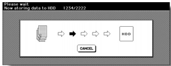
On this screen, touch CANCEL to suspend the storing job, then touch YES on the popup menu to delete the data, or touch NO to continue.
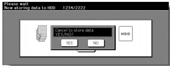
To Transmit Image Data from HDD to PC
Use this function to transmit the image data from the HDD to a PC over a network to store the data in a PC.
We recommend that you should make a copy of the image data stored to HDD periodically, just in case of trouble.
Specifications for Transmitting Image Data from HDD to PC<<
To transmit and store the image data in a PC, a PC must have a specific setup application installed. Follow the instruction according to the setup application installed on a PC.
The data transmission procedure on a PC can be performed automatically by designating it on the touch screen of the machine. (In this case, the setup application installed in the PC should be the Job Editor Server. The Job Editor 2 allows manual transmission only.)
The password specified when storing the data in HDD is required. The image data is to be specified by the given job name.
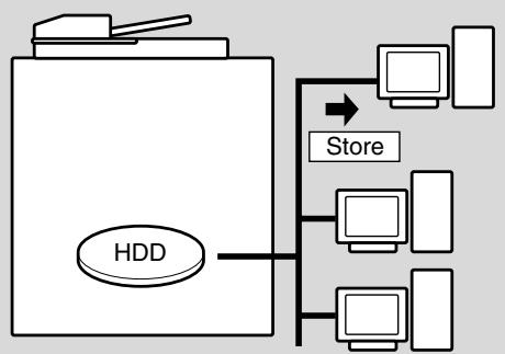
1. Press [MODE] to light up the [SCAN/SERVER] LED.
![KONICA MINOLTA 7255 - Press [MODE] to light up the [SCAN/SERVER] LED. - 1](/content/2025/01/139764/images/a9f9aff16e4042d704f6b4336a8c5cb8ceff5bc5065604b2b641b0c78beb60c9.jpg)
The Scan/Server Setting Menu Screen will be displayed.
2. Touch IMAGE STORE/DELETE.

The Image Data Store/Delete Site Selection Screen will be displayed.
3. Touch HDD PC.
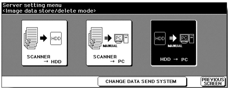
The Image Data Password Entry Screen will be displayed.

FOR DETAILS
- The HDD PC key on the Image Data Store/Delete Site Selection Screen initially indicates "MANUAL" to show that the manual setting on a PC is required to complete the data transmission procedure. Touch CHANGE DATA SEND SYSTEM to change "MANUAL" to "AUTOMATIC" to complete it automatically. See p. 10-11 for detail.
- The initial setting of the data transmission procedure indicated on the HDD PC key can be changed from "MANUAL" to "AUTOMATIC". Refer to the instruction of the setup application.
4. Enter your image data password from the touch screen keypad.
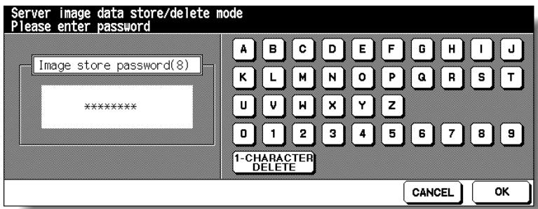
To correct an entry, touch 1-CHARACTER DELETE repeatedly to delete each character, then enter the correct job name.
5. Touch OK.
The Job Selection Screen will be displayed.
6. Touch the desired job name key to highlight it.
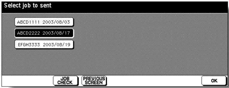
7. Touch OK.
At this time, the Image Data Transmitting Screen appears without the data transmission starting, if a data transmission procedure from the PC is required. In this case, perform the procedure on a PC. The data transmission will start.
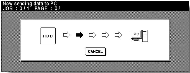

FOR DETAILS
- For the data transmission procedure on a PC side, refer to the instruction of the setup application installed in the PC.
- If TRANSMIT TO SERVER is selected on the Change Data Sending System Screen, any operation on a PC side is not required during the data transmission procedure but the Job Editor Server should be activated in advance. For detailed information, refer to the instruction of the Job Editor Server.
When the data transmission is completed, the popup menu will appear to ask whether you delete the data from HDD.
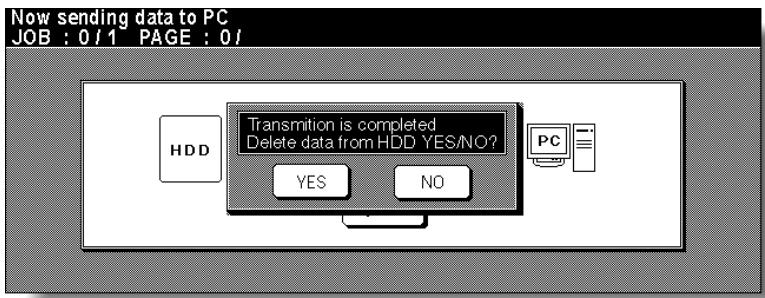
Touch YES to delete the data from HDD, or touch NO to leave it in HDD. The Basic Screen will be restored.

FOR DETAILS: Change Data Sending System Screen
Specify MANUAL: OPERATE ON PC for the PC with Job Editor 2 installed, or AUTOMATIC: TRANSMIT TO SERVER for the PC with Job Editor Server installed.
The Job Editor Server should be activated on a PC in advance when AUTOMATIC: TRANSMIT TO SERVER is specified on this screen.

Procedure
- Touch CHANGE DATA SEND SYSTEM on the Image Data Store/Delete Site Selection Screen to display the Change Data Sending System Screen.
- Touch MANUAL: OPERATE ON PC or AUTOMATIC: TRANSMIT TO SERVER to select it.
- Touch PREVIOUS SCREEN. The Image Data Store/Delete Site Selection Screen will be restored.
Confirm that the indication of the HDD PC key reflects the change when restored.

FOR DETAILS: To Suspend the Data Transmission
To suspend the transmission while the Image Data Transmitting Screen is displayed, touch CANCEL on the screen. On the popup menu displayed as shown below, touch YES to cancel the job, or touch NO to continue.
The data stored in HDD will not be erased by this operation.
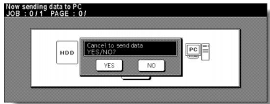
To Delete Image Data from HDD/PC
The password specified when storing the data in HDD/PC is required. The image data is to be specified by the given job name.
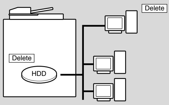
1. Press [MODE] to light up the [SCAN/SERVER] LED.
![KONICA MINOLTA 7255 - Press [MODE] to light up the [SCAN/SERVER] LED. - 1](/content/2025/01/139764/images/016a174338e6ff388fbae33f6e0f4f814b99e5158d8b584ff9979ecbfe8cde00.jpg)
The Scan/Server Setting Menu Screen will be displayed.
2. Touch IMAGE STORE/DELETE.

The Image Data Store/Delete Site Selection Screen will be displayed.
3. Touch SCANNER→HDD or SCANNER→PC.
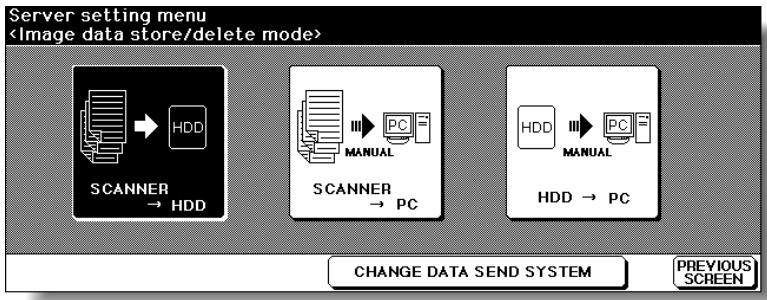
The Image Data Password Entry Screen will be displayed.

HINT
To delete the data stored in a PC, operation on the PC side may be required, depending on the type of setup application installed in the PC. Follow the instruction according to the setup application installed in a PC.
Also refer to the instruction for using the CHANGE DATA SEND SYSTEM key on the screen.
4. Enter your image data password from the touch screen keypad.
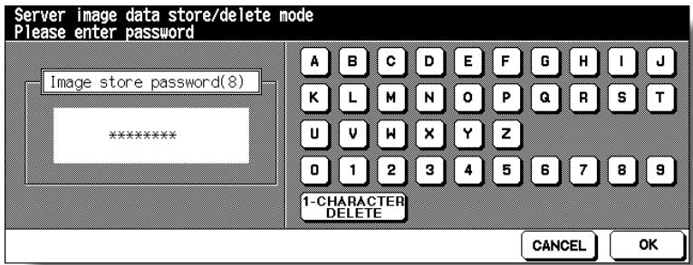
To correct an entry, touch 1-CHARACTER DELETE repeatedly to delete each character, then enter the correct job name.
5. Touch OK.
The Job Name Entry Screen will be displayed.
6. Delete the image data.
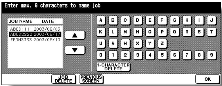
Touch the or key on the right side of the job name list to highlight the name of the data to be deleted, then touch JOB DELETE.
The popup menu will appear to confirm that you delete the selected data.
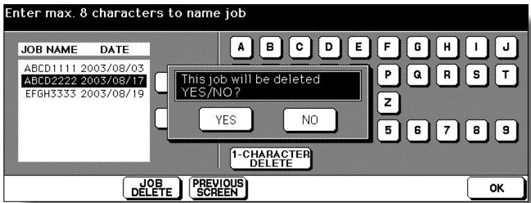
Touch YES to delete the selected data, or touch NO to cancel. The popup menu will disappear.
7. Touch OK to restore the Scan/Server Setting Menu Screen.

FOR DETAILS
To delete the data stored with different password, touch PREVIOUS SCREEN to return to the Image Data Password Entry Screen.
8. Press [MODE] to light up the [COPY] LED.
The Basic Screen will be restored.
Use this function to store the scanned image data in HDD after copying is completed.
![KONICA MINOLTA 7255 - Press [MODE] to light up the [COPY] LED. - 1](/content/2025/01/139764/images/bed1b63a3b653b818b2970d4112e77f84cf7d647e0b0bcfaffb6e517b684a078.jpg)
FOR DETAILS
Installation of the optional HDD (HD-105) is required for this function. With the HDD installed, the HDD STORE key will be displayed on the Output Mode popup menu.
This storing function does not conflict with any copying condition other than Program Job.
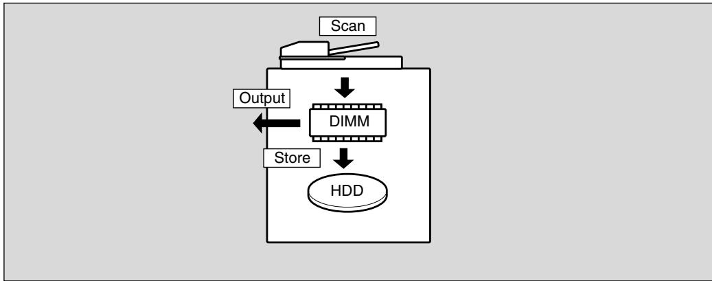
- Touch OUTPUT MENU on the Basic Screen to display the Output Mode popup menu.
- Touch HDD STORE
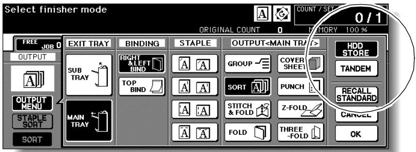
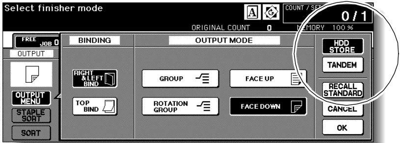
The Image Data Password Entry Screen will be displayed.
3. Enter the desired image data password in up to 8 characters from the touch screen keypad.

To correct an entry, touch 1-CHARACTER DELETE repeatedly to delete each character, then enter the correct password.
4. If the password is correct, touch OK.
The Job Name Entry Screen will be displayed.
5. Enter the desired job name in up to 8 characters from the touch screen keypad.
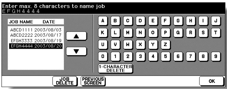
To correct an entry, touch 1-CHARACTER DELETE repeatedly to delete each character, then enter the correct job name.
6. If the job name is correct, touch OK twice to return to the Basic Screen.
The HDD icon is displayed in the message area of the Basic Screen.
7. Select the desired copying conditions, then enter the desired print quantity.
8. Position original(s) FACE UP in the document feeder or FACE DOWN on the platen glass.

HINT
See p. 3-2 to p. 3-5 for details on positioning originals.
9. Press [START] to scan and then print.
When the Store mode is used, touch STORE on the Basic Screen to deselect the Store mode when the store function is completed, i.e., after all originals are scanned, then press [START] to print.
![KONICA MINOLTA 7255 - Press [START] to scan and then print. - 1](/content/2025/01/139764/images/be22cc8493b689a9f50cd5be147fd9ebcb0de7fba2967cd304342f2c940f046d.jpg)
FOR DETAILS
To suspend the scanning or printing job, press [STOP] on the control panel. The popup menu will be displayed to ask you how to complete the current job. Touch CONTINUE to continue the job, EXIT to cancel the job and delete the data, or EXIT after storing data to HDD to store the data in HDD without printing.
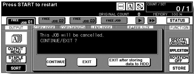
After scanning all the originals, the machine automatically starts to print and store the data in HDD.
When storing job is almost completed, SCANNER HDD icon appears in the message area. Press [AUTO RESET] to restore the initial settings.

FOR DETAILS
If the Memory Switch No. 41 is turned on in the Key Operator setting, the Image Data Storing Screen will be displayed while the image data is stored in HDD. (See p. 13-39 to p. 13-46 for details.)
In this case, touch CANCEL on the Image Data Storing Screen to suspend the storing job, then touch YES on the popup menu to delete the data, or touch NO to continue.
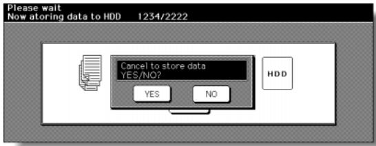
Use this function to recall the image data from the HDD/PC to the built-in DIMM for printing.

FOR DETAILS
- Installation of the optional HDD (HD-105) is required to recall data from HDD.
- To recall data from PC, the machine should be connected to PC by cross-cable, and a specific software for using Server function should be installed in PC.
To recall data stored in the HDD/PC, enter the password specified at the time data was stored, then designate it by the job name.
Use IMAGE COMBINATION to recall several jobs at a time and output them as one job.

FOR DETAILS
- Different output modes specified for combined jobs (e.g. Staple-sort and Sort) cannot be reproduced in the output copies.
- Different job types (e.g. copy job and print job) can be combined.
- Combined jobs should have the same setting in the following conditions: APS, Photo mode, Binding direction of the duplex originals
- The job with any of the following conditions specified cannot be combined: Mixed Original, Image Insert, Book Copy, Program Job, Repeat, Overlay
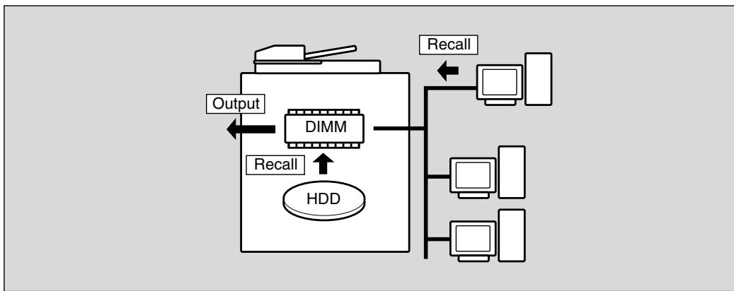
1. Press [MODE] to light up the [SCAN/SERVER] LED.
The Scan/Server Setting Menu Screen will be displayed.
![KONICA MINOLTA 7255 - Press [MODE] to light up the [SCAN/SERVER] LED. - 1](/content/2025/01/139764/images/7c10bb4ec79881e21a1a8c3e9bbe8214ad9b6333ba31d528f17243749ec0a3f3.jpg)
2. Touch IMAGE RECALL.
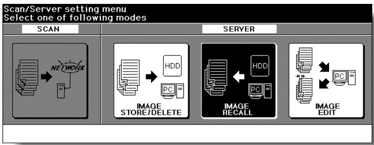
The Image Data Password Entry Screen will be displayed.
3. Enter your image data password from the touch screen keypad.
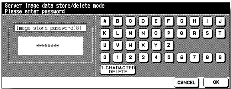
To correct an entry, touch 1-CHARACTER DELETE repeatedly to delete each character, then enter the correct job name.
4. Touch OK.
The Recall Job Selection Screen will be displayed.
5. Select the job to be recalled.
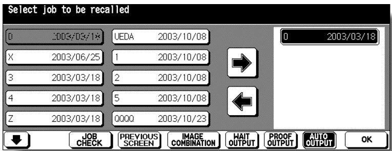
Touch the desired job name key to highlight it, then touch to move it to the recall list on the right side. To use Image Combination, touch IMAGE COMBINATION before touching .
Touching JOB CHECK displays the Check Screen to allow you to view all the feature selections made for that job.

FOR DETAILS
- To cancel the job moved to the recall list, touch the job name in the list to highlight it, then touch to return it to the left side key.
- Two or more jobs can be combined and output as one job, provided that those jobs have been stored with the same copying conditions. Use Image Combination, if desired.
6. If the desired job name is displayed in the recall list, touch WAIT OUTPUT, PROOF OUTPUT, or AUTO OUTPUT, as desired.
Follow the procedure below according to the selected output mode key to complete the image recall and output operation.
Selecting WAIT OUTPUT:
(1) Touch OK.
When the data transmission is completed, the Basic Screen will be displayed reflecting the settings made for that job.
(2) Enter the desired print quantity, then press [START] to print.
Selecting PROOF OUTPUT:
(1) Touch OK. The data transmission starts with the Basic Screen restored. When the data transmission is completed, a sample copy is output, then the Check Screen will be displayed.
(2) Check the sample copy, then change the copy conditions if required. Enter the desired print quantity, then press [START] to print.
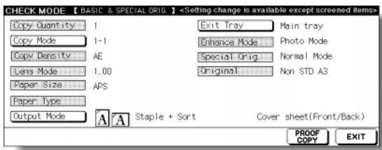
Selecting AUTO OUTPUT:
(1) Touch OK. The popup menu to enter the print quantity will be displayed.
(2) Enter the desired print quantity, then touch OK.
When the data transmission is completed, the machine automatically starts to print.
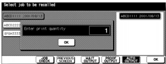

FOR DETAILS
Key Operator can set the machine to return to the Recall Job Selection Screen when printing job is completed, so that the data recalling can be continued. See p. 13-39 to p. 13-46.
In this case, the Image Data Recalling Screen will be displayed while the data is recalled.
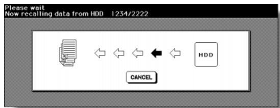
On this screen, touch CANCEL to suspend recalling.
On the popup menu displayed, touch YES to delete the data recalled to DIMM, or touch NO to continue.
The data stored in HDD/PC will not be erased by this operation.
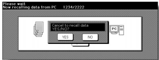
Use this function to transmit a scanned image data to PC to edit it, and return the edited data to DIMM for printing.
The edited image data cannot be stored and will be deleted when printing job is completed.

FOR DETAILS
To use this mode, the machine should be connected to PC by cross-cable, or with network provided that a specific software for using Server function is installed in PC.
>>>Specifications for Editing Image Data<<
Incompatible Conditions: 1-2, 2-2, AMS, Selecting output mode, Selecting paper size (APS is automatically selected), Setting print quantity, Rotation, FULL AREA in Non STD Size, Sheet/Cover Insertion, Chapter, Combination, Booklet, OHP Interleave, Image Insert, Dual Page, Program Job, Non-Image Area Erase, Reverse Image, Repeat, AUTO Layout, Image Shift, Stamp/Overlay
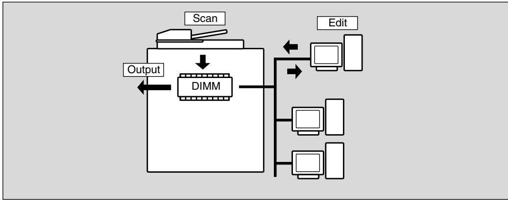
1. Press [MODE] to light up the [SCAN/SERVER] LED.
![KONICA MINOLTA 7255 - Press [MODE] to light up the [SCAN/SERVER] LED. - 1](/content/2025/01/139764/images/68e8b9745e6f2759ae1306fe0c30a4fc5f3b2f753b087536582cdc57a0688a70.jpg)
The Scan/Server Setting Menu Screen will be displayed.
2. Touch IMAGE EDIT.

The Scanner Setting Screen will be displayed.
3. Select the desired scanning conditions.
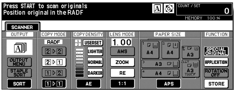
Print quantity cannot be entered.
4. Position original(s) FACE UP in the document feeder or FACE DOWN on the platen glass.

HINT
See p. 3-2 to p. 3-5 for details on positioning originals.
5. Touch STORE on the Scanner Condition Selection Screen to highlight it.
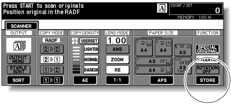
6. Press [START] to scan.
After scanning is completed, the Image Data Edit Screen will be displayed to indicate that the scanned image data is ready for transmission.
![KONICA MINOLTA 7255 - Press [START] to scan. - 1](/content/2025/01/139764/images/075de6464d3aee4fa56a613eb325907d8aa363e8429e4e2113fc8094496a1162.jpg)
![KONICA MINOLTA 7255 - Press [START] to scan. - 2](/content/2025/01/139764/images/2756322713fc3da53078608022d8ddcf6a8455d233f69217f17d3cdd6c8b6968.jpg)
FOR DETAILS
To stop the Image Edit operation while the Image Data Edit Screen is displayed, touch EXIT. If the popup menu shown below is displayed, touch YES to cancel the editing job and delete the image data, or touch NO to continue.
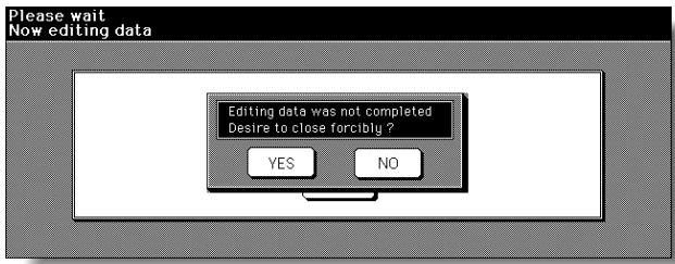
7. Perform the data transmission procedure on PC, then edit the image data as required.

HINT
For details, refer to the instruction manual for Image Edit mode.
When completed, make a setting on PC to return the edited data to DIMM. The Basic Screen will be restored.
8. Press [START].
The copier starts the printing job.
When printing is completed, edited data will be deleted automatically.
When the machine is connected with a PC over a network, the web browser activated on the PC provides the following functions.
1 Main Page
Displays the job in progress, service call, and machine information.
2 Job Status
Displays the current and previous job status.
3 HDD Job Information
Searches the built-in HDD for an image data by job name, then checks, outputs, or deletes the image data. You can also change the job name of the image data.
To use this function, the optional HDD is required in the machine.
4 Environment Setup
Performs the Key Operator setting concerning network environment.
Browser: Internet Explorer 5.5 SP2 / Netscape 4.7 or later
Follow the procedure below to access the Web Utilities of the machine using the web browser.
- Turn on the power to the PC connected with the machine over a network.
![KONICA MINOLTA 7255 - Press [START]. - 1](/content/2025/01/139764/images/f587e6eda08a29c3189da29cc2c9e73b1709f27b92f19a1e5adcf7ce78a9ad3b.jpg)
DETAILS
Contact your network manager for details on the network system.
- Activate the web browser, then select [Open] from the File menu.
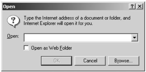
- Enter the URL (http:// [IP address or host name of the machine]), then click on [OK] .

DETAILS
Ask your network manager for the IP address or host name of the machine.
The Main Page of the Web Utilities will be displayed.
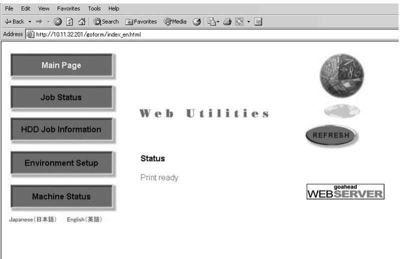
The Main Page informs you of the current job status of the machine and the maintenance item, if required.
Service call
JAM
- Paper supply
- Toner supply
- Staple cartridge supply
- Dispose ot Punch waste basket
PM call

DETAILS
- Click on [REFRESH] in the Web Utilities window to update the information.
- The Web Utilities window is subject to change without notice.
This section uses the 7272 as an example.
Follow the procedure below to display the machine information using the web browser.
1. Open the Web Utilities window.

HINT
See p. 10-26 for detailed procedure to access the Web Utilities.
2. Click on [Machine Status].
![KONICA MINOLTA 7255 - Click on [Machine Status]. - 1](/content/2025/01/139764/images/7cf32c455cb0759de6c36c47b936e151880fa128edbd5f5e131894aa5d394254.jpg)
The window now provides the paper tray configuration, engine configuration, and option information.
![KONICA MINOLTA 7255 - Click on [Machine Status]. - 2](/content/2025/01/139764/images/96c66ff4de461ca87992b6fab4463ae5f0b535725f264815e0e9024acb893886.jpg)
DETAILS
The same information will be provided also in the Job Status window. See p. 10-29.
Paper Tray Configuration
| Paper Tray | Size | Type | Status |
| Manual Tray | A3 | Normal | No Paper in Tray |
| Tray1 | A4 | Normal | Paper in Tray |
| Tray2 | A4 | Normal | No Paper in Tray |
| Tray3 | A4R | Normal | Paper in Tray |
| Tray4 | A5 | Normal | No Paper in Tray |
Engine Configuration
| Machine Type | 7272 |
| Country Code | Europe |
| Display Language | English |
| ERDH Capacity(MB) | 64 |
| ERDH Available(%) | 100 |
| Total Count | 371 |
| Printer Count | 13 |
| Total PM Count | 371 |
| Developer Count | 371 |
| Drum Count | 371 |
Option Information
| Finisher | Not Mount |
| ADU | Mount |
| DF Type | DF-322 |
| HDD | Not Mount |
| LCT | Not Mount |

DETAILS
Click on [REFRESH] in the window to update the information.
To Display Current Machine Status (Job Status)
Follow the procedure below to display the current job status, job list including reserved jobs and job information, and information on up to 16 previous jobs.
1. Open the Web Utilities window.

HINT
See p. 10-26 for detailed procedure to access the Web Utilities.
2. Click on [Job Status].
![KONICA MINOLTA 7255 - Click on [Job Status]. - 1](/content/2025/01/139764/images/ec846b0ad9e4595fd99d857d1cfb603e77ee9a9efc1109235889a3eed2dbdf7f.jpg)
The current job status, number of jobs in waiting, and remaining time to elapse before completing the print job.
![KONICA MINOLTA 7255 - Click on [Job Status]. - 2](/content/2025/01/139764/images/f474a8435d2a010987b9655dfe56dd80fff87dcdd267aea2c3a29b720095d06a.jpg)
DETAILS
- Clicking on [7272] will display the machine information. See p. 10-28.
- Click on [REFRESH] to update the information.
3. Display the current job or reserved job information.
Click on the desired [Job Priority No.] under the "Job List".
The information on the specified job will appear in the second "Job List" area.
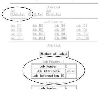
DETAILS
If no print job or reserved job exists, "Job Empty" will be displayed in the first "Job List" area.
4. Display the previous job information.
Click on the desired [Job ID No.] under the "Job Status".
The information on the specified previous job will appear in the second "Job Status" area.
Number of Job 0
Job Status
| Job Number | 1 |
| Number of Pages | 2 |
| Print Quantity | 1 |
| Output Time | 0 |
| Job Attributes | Copier |
| Job Status | Job end successfully |
| Current print quantity count | 1 |
| Current page number | 2 |
| Remaining Time | 0 |
| Job Number | 2 |
| Number of Pages | 4 |
| Print Quantity | 1 |
| Output Time | 0 |
| Job Attribute | Copier |
| Job Status | Job end successfully |
| Current print quantity count | 1 |

DETAILS
If no print job has been made after the machine powered on, no indication will appear in the first "Job Status" area.
Operating Image Data Stored in HDD (HDD Job Information)
Use the web browser to search the built-in HDD for an image data, then check, output, or delete the image data.
Changing the job name given to the image data is also available.
This function is available only when the optional HDD is installed in the machine.
1. Open the Web Utilities window.

HINT
See p. 10-26 for detailed procedure to access the Web Utilities.
2. Click on [HDD Job Information].
3. Enter the Image Recall Password, then click on [Apply].
![KONICA MINOLTA 7255 - Enter the Image Recall Password, then click on [Apply]. - 1](/content/2025/01/139764/images/21a8ba0fcf2005efee86c7c209572d116d9f9184b8ac9c058526ccfbc0f49241.jpg)
HINT
The Image Recall Password is the image data password entered in up to 8 characters when the image data was stored in HDD. See p. 10-5, 10-10, 10-14 or 10-17 for details.
![KONICA MINOLTA 7255 - Enter the Image Recall Password, then click on [Apply]. - 2](/content/2025/01/139764/images/b24c68278cae5bb54a54e86f4ec948926ec67917ae32d0e321255c637622b2b8.jpg)
The Job Search text box and the Job List will be displayed in the window. The list is made of the jobs stored with the same image data password and arranged in alphabetical order.
![KONICA MINOLTA 7255 - Enter the Image Recall Password, then click on [Apply]. - 3](/content/2025/01/139764/images/221992dbb16644437f6d48c9936849320bed068adb33b2966d20cbd9fbfea3b0.jpg)
![KONICA MINOLTA 7255 - Enter the Image Recall Password, then click on [Apply]. - 4](/content/2025/01/139764/images/014f19d28c5ab57bdb665195f967d8ec9173ea8f2035e34fb9390dc880a967af.jpg)
DETAILS
- The Job List indicates the job name, saved date, and the page count. The "P Job" in the page count column indicates that the data was stored using Program Job function.
- All the image data stored in HDD will be checked and those having the same image data password will be listed.
- The printer data stored in HDD will also be listed.
4. Search the desired image data.
To search a specific image data, enter the job name of the desired image data in the Job Search text box, then click on [Search].
The result will be displayed as a list.

DETAILS
- The search will be performed over the jobs having the same image data password collected in step 3. You cannot make a search of all the jobs for the given job name.
- The printer data stored in HDD will also be listed.
5. Check the image data information.
Click on [Image] on the right side of the desired job name to view the contents. The reduced image of the first page of the selected data and detailed information will be displayed.
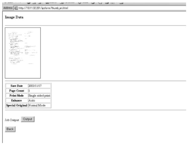
Click on [Output] to print the image data. Proceed to step 6. Choosing [Back] will resume the searched job list.
6. Output the image data.
Click on [Output] on the right side of the desired job name to print out the image data. The Output Setting dialogue box will be displayed.
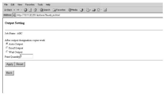
If the machine is under the control of EKC function, enter the 8-digit EKC password. Choose [Auto Output], [Proof Output], or [Wait Output], as desired.
Click on [Back] to cancel the output setting.

DETAILS
If incorrect EKC password is entered, the print job cannot be completed successfully and the message displayed in the "Result of job print" dialogue box will inform you that the wrong password was entered.

HINT
See p. 13-15 for details of the EKC setting.
Selecting Auto output:
Enter the desired print quantity, then click on [Apply].
The machine starts to output the specified number of copied sets, then the "Result of job print" dialogue box will appear when completed.

DETAILS
The web browser does not allow you to cancel the printing job, if it is currently in progress.
Use the machine to stop printing.
Selecting Proof output:
Enter the desired print quantity, then click on [Apply].
A sample copy will be output and the Check Screen will be displayed on the touch screen of the machine.
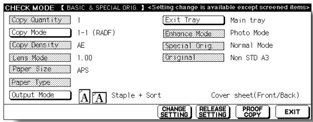
Check the sample copy, change the copy conditions if required, then press [START] on the control panel of the machine to output the rest except the sample set.
The "Result of job print" dialogue box will appear when print job is completed.
Selecting Wait output:
Enter the desired print quantity, then click on [Apply].
The image data will be recalled but held to be output, then the Basic Screen will be displayed on the touch screen of the machine.
Select the desired copy conditions and enter the desired print quantity, then press [START] on the machine control panel.
Choosing [Back] will resume the Job list dialogue box.

DETAILS
When selecting Auto output or Proof output, only the web browser setting allows the print quantity to be specified.
When selecting Wait output, the print quantity entered in the web browser can be changed on the machine control panel before pressing [START].
7. Delete the image data.
Click on [Delete] on the right side of the desired job name to delete the image data.
The Job Delete dialogue box will be displayed.
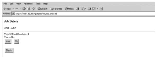
Click on [Yes] to delete the data.
Choosing [Back] will resume the Job list dialogue box.

DETAILS
- The printer data stored in HDD will also be deleted.
- Once deleted, the job cannot be restored.
8. Change the job name of the image data.
Click on [Rename] on the right side of the desired job name to change the job name of the image data.
The Change Job name dialogue box will be displayed.
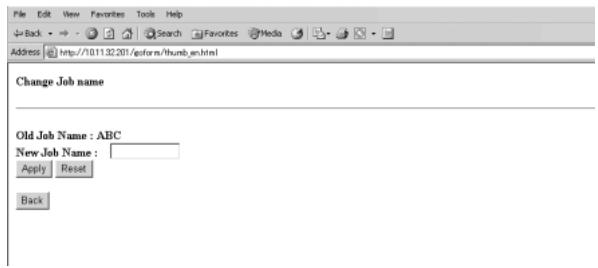
Enter the new job name using alphabets and numbers, then click on [Apply]. Choosing [Back] will resume the Job list dialogue box.

DETAILS
Clicking on [Apply] will be ignored if the entered job name is already used.
The job name cannot also be changed if any symbols other than alphabets and numbers are entered.
Setting E-Mail Transmission Function (Environment Setup)
Perform the Key Operator setting concerning the network environment using the web browser.
For details of the E-Mail Transmission Setting, refer to p. 13-8.
1. Open the Web Utilities window.

HINT
See p. 10-26 for detailed procedure to access the Web Utilities.
2. Click on [Environment Setup].
3. Display the E-Mail Transmission Setting window.
Enter the 4-digit Key Operator password, then click on [Apply].

Click on [E-Mail transmission setting].
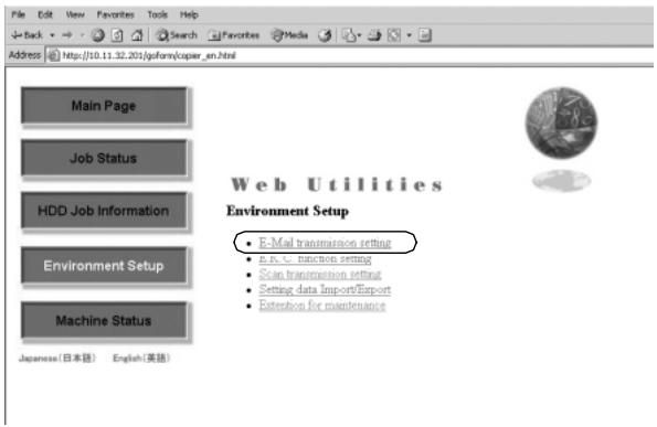
The E-Mail Transmission Setting window will be displayed.

DETAILS
The Extension for maintenance option will be exclusively used by a service representative.
4. Perform the setting.
Enter the IP address of the mail server, IP address of the DNS server (if needed), time difference, and E-mail address to be informed of the machine status.
Click on the check box of the desired transmission item.
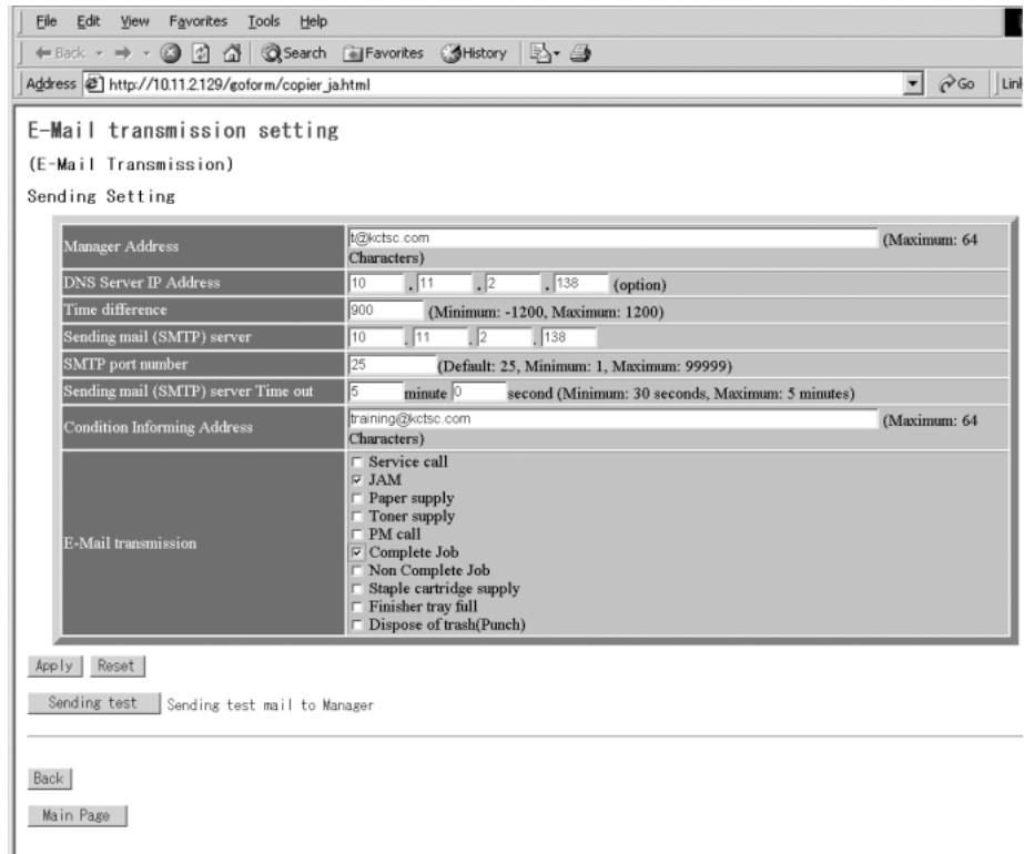
Click on [Apply] to complete the setting and return to the Web Utilities window.
Clicking on [Reset] will void the setting and restore the Web Utilities window.
Clicking on [Sending test] will send a test mail to the manager.
Make the following Key Operator settings concerning the E.K.C. function using the web browser on a PC.
E.K.C. Data Add (see step 4.)
Add a new E.K.C. data (password, name, and copy limit) to the E.K.C. list.
E.K.C. Data List (see step 5.)
Change or delete the E.K.C. data (password, name, or copy limit) in the list, or reset the counters.
E.K.C. Function Setting (see step 6.)
Specify the following E.K.C. function settings.
Switching the E.K.C.: ON/OFF
Effect when the copy limit is reached: Immediately / After job / Warning E.K.C. password: 8 digits / under 8 digits
E.K.C. password input timing: Auto reset timer/ Complete job
Wrong E.K.C. password (from printer): Accept / Reject

DETAILS
The above settings can also be made on the machine itself, except for the Wrong E.K.C. password (from printer) setting. Some settings may require operations on the machine.
Refer to pages 13-15 and 13-39 to 13-46.
1. Open the Web Utilities window.

HINT
See p. 10-26 for detailed procedure to access the Web Utilities.
2. Click on [Environment Setup].
3. Display the E.K.C. Function Setting window.
Enter the 4-digit Key Operator password, then click on [Apply].

Click on [E.K.C. function setting].
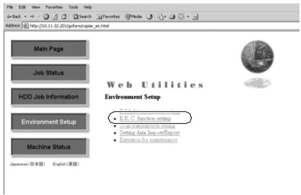
The Enter Network Password dialog box will be displayed.
Enter "ekc" in the User Name text box, and an 8-digit master key code in the Password text box, then click on [OK].
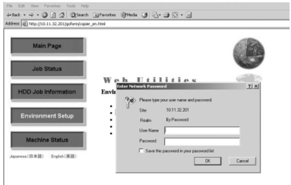
The E.K.C. Function Setting menu window will be displayed.
4. Add an E.K.C. data.
Click on [E.K.C. data add] in the E.K.C. Function Setting menu window.
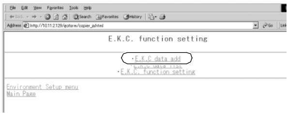
The E.K.C. Data Setting window will be displayed.
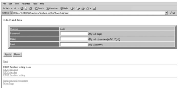
Enter the following items to register a new E.K.C. data, then click on [Apply].
Number: Automatically assigned
Password: 8 digits max.
Name: 8 characters max.
Limit: 999,999 copies max.

DETAILS
To clear the text boxes, click on [Reset].
To cancel adding a new E.K.C. data, click on [Back] or any E.K.C.
Function Setting menu item to jump to the desired window.

DETAILS: Error Message
- A duplicate password or name will be rejected with an error message. However, duplicating a password is possible using the Key Operator setting. See p. 13-18.
- The Name entry box accepts letters (capital letters only), numbers, and four symbols: (,) , - , and / . Any other symbols will be rejected with an error message displayed in the window.
- Max. 1,000 E.K.C. entries can be registered. An error message will be displayed if the above limit is exceeded.
- An error message may be displayed when the data entry has not been completed due to the machine operation in progress. Please click on [Apply] while the machine is in an idle state.
The registered content will be displayed in the window.
The new E.K.C. data will be transmitted to the machine immediately so that is valid for the user operations.
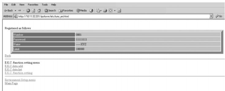
Click on [Back] to return to the E.K.C. Function Setting menu window or any menu item to jump to the desired window.
5. Edit the E.K.C. data.
Click on [E.K.C. data list] in the E.K.C. Function Setting menu window or from the menu in any subsequent window.

The E.K.C. Data List window will be displayed.
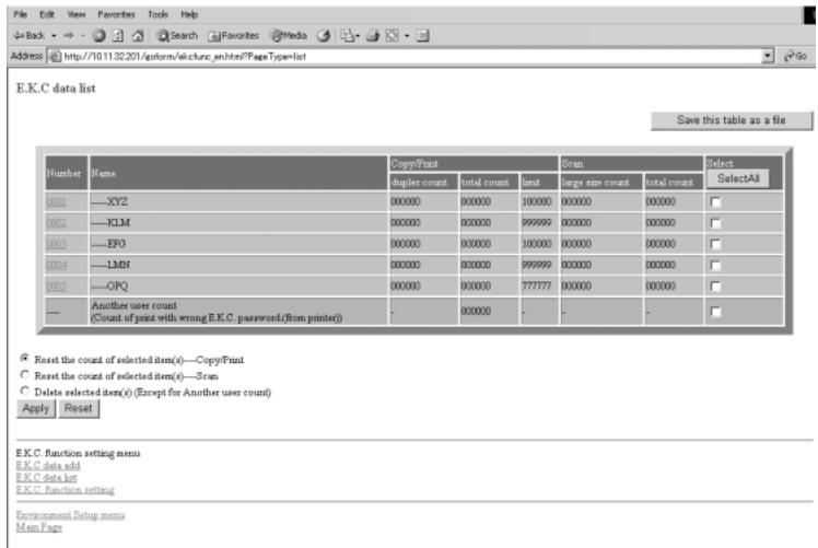

HINT
The "Another user count" in the list indicates the count accumulated for the jobs performed by non-registered users. This data cannot be edited other than resetting the counter.
To change Password, Name, or Limit:
(1) Click on the number of the data to be edited.
The E.K.C. Edit Setting window will be displayed.
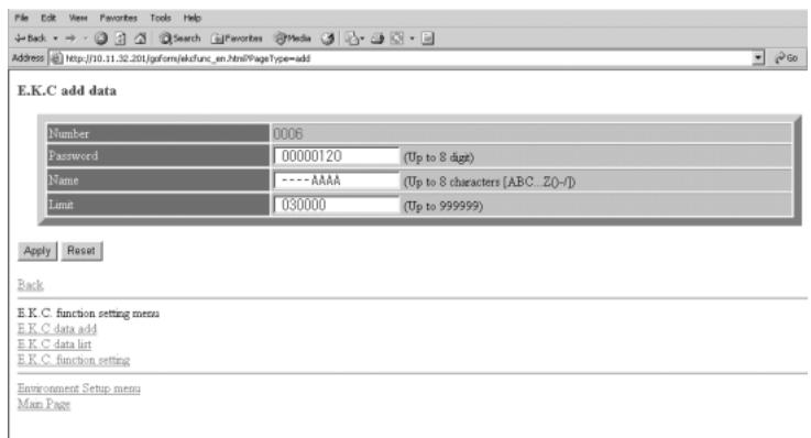
(2) Change the password, name, or limit, as desired. For details in entering procedure, refer to p. 10-39.
(3) Click on [Apply].

DETAILS
To clear the text boxes, click on [Reset].
To cancel editing the E.K.C. data, click on [Back] or any E.K.C. Function Setting menu item to jump to the desired window.

DETAILS: Error Message
See "Details" on p. 10-39 if an error message is displayed after clicking on [Apply].
The edited content will be displayed in the window.
The edited data will be transmitted to the machine immediately so that is valid for the user operations.
Click on [Back] to return to the E.K.C. Data List window.
To reset E.K.C. count:
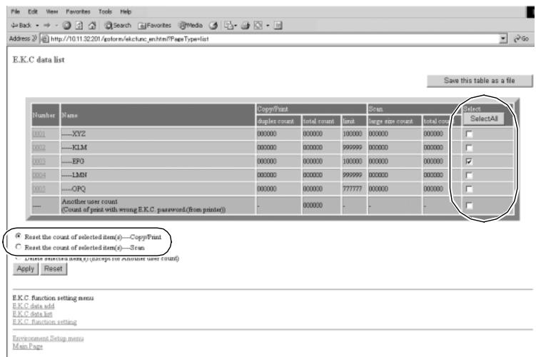
(1) Click on the check box(es) to select the E.K.C. data of the counter to be cleared. If all the counters are to be cleared, click on [SelectAll].
(2) Click on the radio button (a white circle) heading the "Reset the count of selected item(s)....Copy/Print" or "Reset the count of selected item(s).... Scan."
(3) Click on [Apply].
The Count Reset Confirmation window will be displayed.
![KONICA MINOLTA 7255 - Click on [Apply]. - 1](/content/2025/01/139764/images/1ceabf31f5b5403f08bcac92042b1d54ccae4521a21aaadcf1b4684e7c759e72.jpg)
![KONICA MINOLTA 7255 - Click on [Apply]. - 2](/content/2025/01/139764/images/796f4fd7da228bb37cf9f0e93c743256371112851ad87164b16e09b57c82066e.jpg)
DETAILS
To cancel resetting the E.K.C. data, click on [Back] or any E.K.C. Function Setting menu item to jump to the desired window.
(4) Click on [Apply] to immediately reset the counters to zero.
The message "Setting was changed" will be displayed.
![KONICA MINOLTA 7255 - Click on [Apply] to immediately reset the counters to zero. - 1](/content/2025/01/139764/images/06aa4076e7f794ce4c7b48c8b6c5823aeb760a0dc232d6297282a54128ed7c24.jpg)
![KONICA MINOLTA 7255 - Click on [Apply] to immediately reset the counters to zero. - 2](/content/2025/01/139764/images/1d630c996bb5723eeff98ba2fee958ec128d3917ac10a19f76847ffa52112bec.jpg)
DETAILS: Error Message
If an error message is displayed after clicking on [Apply], a counter has not been reset due to a machine operation in progress. The machine must be in an idle state when you click on [Apply].
Click on [Back] to return to the E.K.C. Data List window.
To delete E.K.C. data:
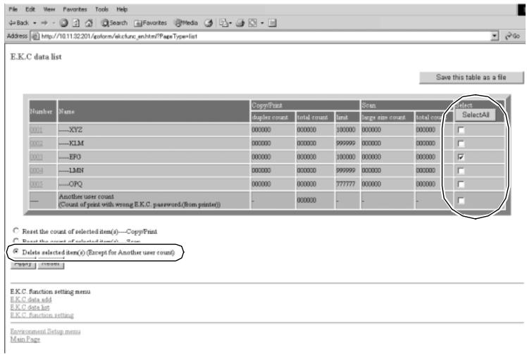
(1) Click on the check box(es) to select the E.K.C. data to be deleted. If all the data are to be cleared, click on [SelectAll].
(2) Click on the radio button (a white circle) heading the "Delete selected item(s) (Except for Another user count)."
(3) Click on [Apply].
The Delete Confirmation window will be displayed.
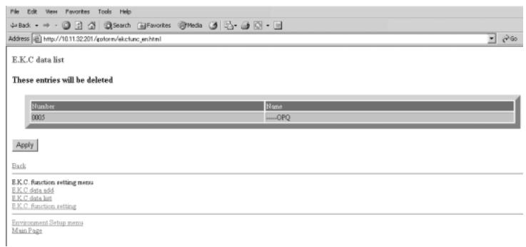

DETAILS
To cancel deleting the E.K.C. data, click on [Back] or any E.K.C. Function Setting menu item to jump to the desired window.
(4) Click on [Apply] to immediately delete the data.
The message "Setting was deleted" will be displayed.
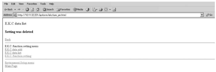

DETAILS: Error Message
If an error message is displayed after clicking on [Apply], data has not been deleted due to a machine operation in progress. The machine must be in an idle state when you click on [Apply].
Click on [Back] to return to the E.K.C. Data List window or any menu item to jump to the desired window.
To save E.K.C. data list as a file:
(1) Click on [Save this table as a file].
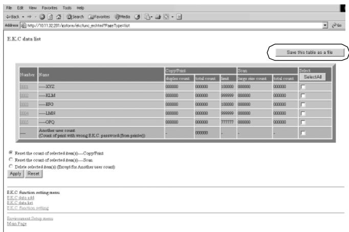
(2) Click on the radio button heading "Save this file to disk," then click on OK.
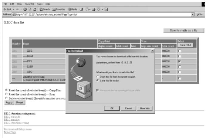
(3) In the dialog box, designate the folder for saving the data, then click on [Save].
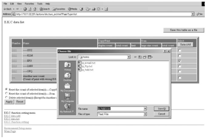

DETAILS
- The E.K.C. data will be stored in CSV format.
- The data cannot be saved while the machine is in operation. In this case, try this procedure again after the machine starts idling. Click on [Back] in the browser window to return to the E.K.C. Data List window for starting over.
Example: E.K.C. data list stored as a file
The "Another user count" will be stored by the name of "UNKNOWN" in the last line.
NUMBER, PASSWORD, NAME, DUPLEXCOUNT, COUNT, LIMIT, S CANLARGECOUNT, SCANCOUNT
0001,00000001,KITA,000000,000000,000010,000000,000000
0002,00000002,TANAKA,000000,000000,000020,000000,000000
0003,00000003,YUZU,000000,000000,000030,000000,000000
0004,00000004,ISAMI,000000,000000,000040,000000,000000
0005,00000005,SUZUE,000000,000000,000060,000000,000000
0006,00000006,REAL,000000,000000,000070,000000,000000
0007,00000007,ISHII,000000,000000,00080,00000,00000
1001,0000000,UNKNOWN,000000,000000,000000,000000,000000
6. Set the E.K.C. function.
Click on [E.K.C. function setting] in the E.K.C. Function Setting menu window or from the menu in any subsequent window.
The E.K.C. Function Setting window will be displayed.
Click on the radio button (white circle) of the desired selection item(s) so that a black dot appears in it.
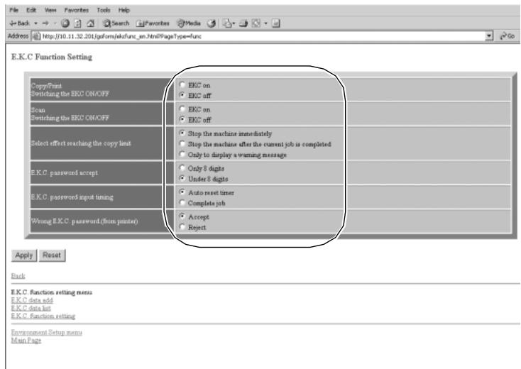
Click on [Apply]. The change made in the settings will be transmitted immediately for the user operations.

DETAILS
To restore the previous setting, click on [Reset].
To cancel the E.K.C. function setting, click on [Back].

DETAILS: Error Message
If an error message is displayed after clicking on [Apply], a setting has not been completed due to a machine operation in progress. The machine must be in an idle state when you click on [Apply].
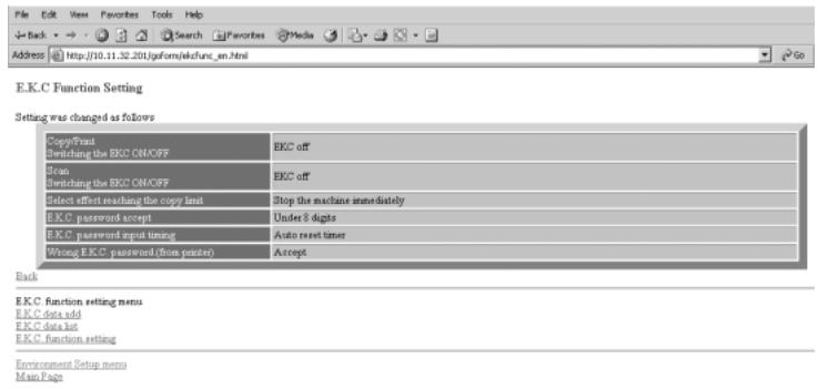
Click on [Back] to return to the E.K.C. Function Setting menu window or any menu item to jump to the desired window.
Setting Scan Transmission Function (Environment Setup)
Follow the procedure below to register, change, or delete the address for the transmission of the scanned image data using the web browser.

DETAILS
Using Scan Transmission Setting in the Key Operator mode, you cannot newly register an E-mail/HDD/FTP address or group the entries.
Specifications for Scan Transmission Setting<<
The Scan Transmission Setting is available only when the optional Printer Controller is installed in the machine.
1. Open the Web Utilities window.

HINT
See p. 10-26 for detailed procedure to access the Web Utilities.
2. Click on [Environment Setup].
3. Display the E-Mail Transmission Setting window.
Enter the 4-digit Key Operator password, then click on [Apply].
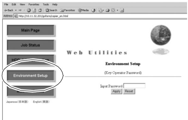
Click on [Scan transmission setting].

The Scan Transmission Setting window will be displayed.

DETAILS
The [Scan transmission setting] key appears in the window only when the optional Printer Controller is installed in the machine.
4. Register the E-Mail, HDD, and FTP, as required.
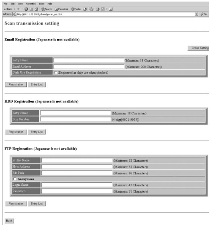

DETAILS
- Click on the DAILY USE check box in the E-mail Registration table, if the data is frequently used.
- The symbols that cannot be displayed in the entry box will be ignored, if entered.
- The HDD Box No. will be registered as a 4-digit number. For example, entering [1] will be registered as [0001].
Click on [Registration] to complete the entry.
The registered content will be displayed.
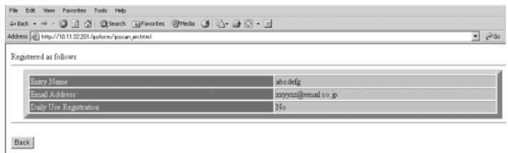
Click on [Back] to return to the Scan Transmission Setting window.
5. Display the Entry List.
Click on [Entry List] of the desired item under the entry box to display the Entry List.
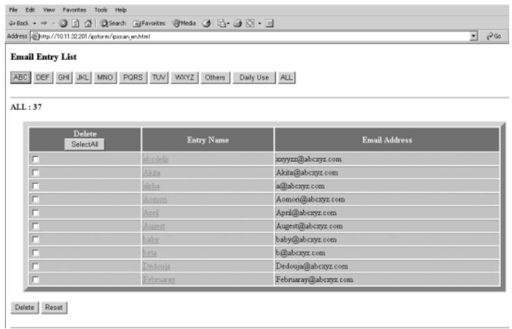
Click on [Back] to return to the Scan Transmission Setting window.
6. Change the registered contents.
Display the Entry List of the desired item as described in step 5. Click on the entry name to be changed.
The window for changing the selected item will be displayed.
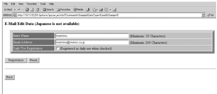
Change the contents as desired, then click on [Registration]. The registered content will be displayed.
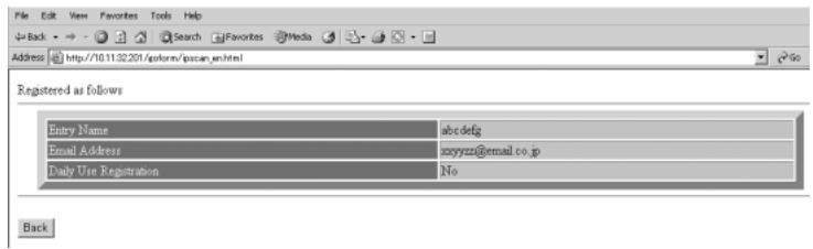
Click on [Back] to return to the Scan Transmission Setting window.
7. Delete the registered contents.
Display the Entry List of the desired item as described in step 5.
Click on the check box in the "Delete" column of the item to be deleted, then click on [Delete].
The window for deleting the selected item will be displayed.
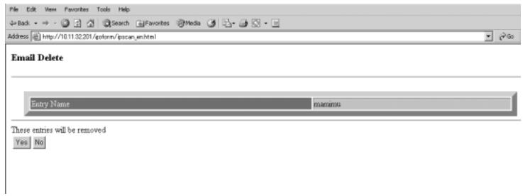

DETAILS
Click on the check box again to release the selection.
Confirm the registered name to be deleted, then click on [Yes].
Click on [Back] to return to the Scan Transmission Setting window.
8. To use grouping function, display the Group Setting window.
Click on [Group Setting] on the Scan Transmission Setting window.
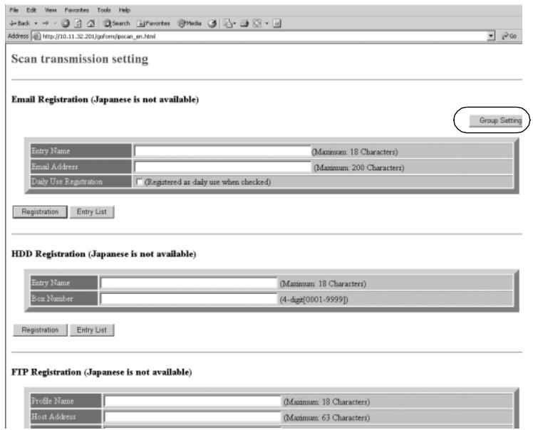
The Group Setting window will be displayed.
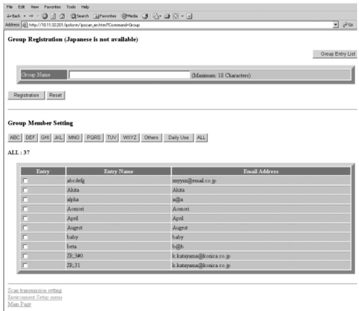
To group the E-mail data:
Enter the desired group name.
Click on an alphabetical order key to display the E-mail data to be included in the group, click on the check box heading the data, then click on [Registration]. The registered content will be displayed.
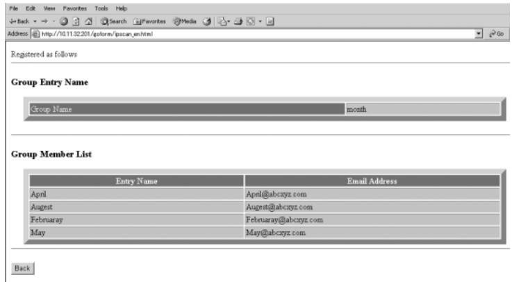
Click on [Back] to return to the Scan Transmission Setting window.
To display the Group Entry List:
Click on [Group Entry List]. The registered group names and members will be displayed in a list.
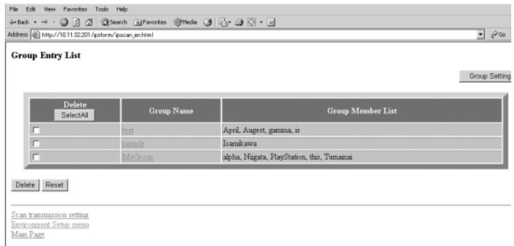
Click on [Reset] to return to the Scan Transmission Setting window.
To change the registered content in a group:
Click on [Group Entry List] to display the list, then click on a group name to be changed. The Group Setting window of the selected group will be displayed.
Change the contents as desired, then click on [Registration]. The registered content will be displayed.
Click on [Back] to return to the Scan Transmission Setting window.
To delete a group:
Click on [Group Entry List] to display the list, then click on a check box heading the group name to be deleted.
Click on [Delete]. The Group Delete confirmation window will be displayed.
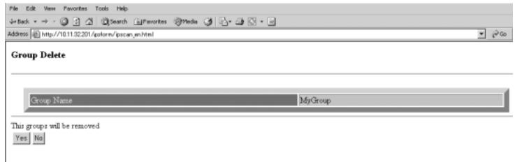
Check the group name to be deleted, then click on [Yes]. To cancel the procedure, click on [No]. In either case, the Group Entry List window will be restored.
Transmitting/Editing Machine Setting File (Environment Setup)
Follow the procedure below to transmit the following setting file from the machine to a PC (export) using the web browser, edit the setting data on the PC, then return the file to the machine (import).
E.K.C. data (max. 1,000 files)
- Three Scan Transmission Setting data
E-mail data (max. 1,008 files)
HDD (Box No.) (max. 48 files)
FTP (FTP server address) (max. 48 files)

DETAILS
- The machine setting file can be stored in a PC so that it may be returned to the machine at any time, and is available for common use if you have two or more machines.
The file transmitted to a PC, being converted to a file type for batch processing, can be edited efficiently and returned to the machine. - The file transmitted to a PC normally contains the four data types mentioned above, however, each data type can be made into a file and transmitted separately. For details of E.K.C. data, see p. 13-17. For details of Scan Transmission Setting data, see p. 13-53.
- The exported setting file of this machine can be imported to another model, and vice versa. For details, contact your service representative.
1. Open the Web Utilities window.

HINT
See p. 10-26 for detailed procedure to access the Web Utilities.
2. Click on [Environment Setup].
3. Display the Setting File Import/Export window.
Enter the 4-digit Key Operator password, then click on [Apply].
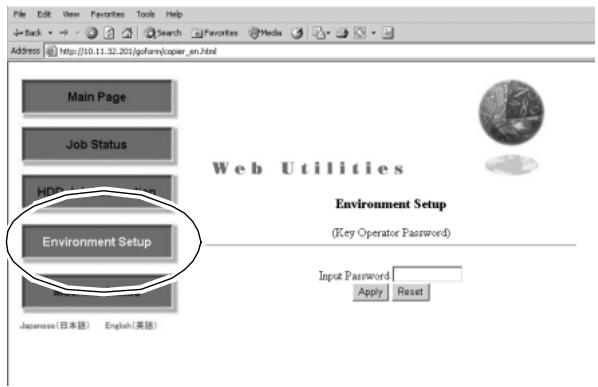
Click on [Setting data Import/Export].
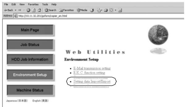
The Enter Network Password dialog box will be displayed.
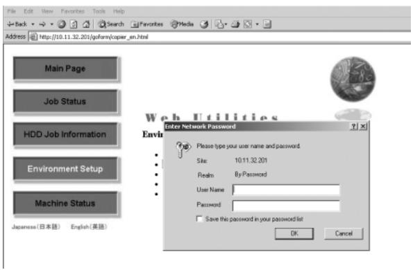
Enter "ekc" in the User Name text box, and an 8-digit master key code in the Password text box, then click on [OK].
The Setting File Import/Export window will be displayed.
4. Export the machine setting file.
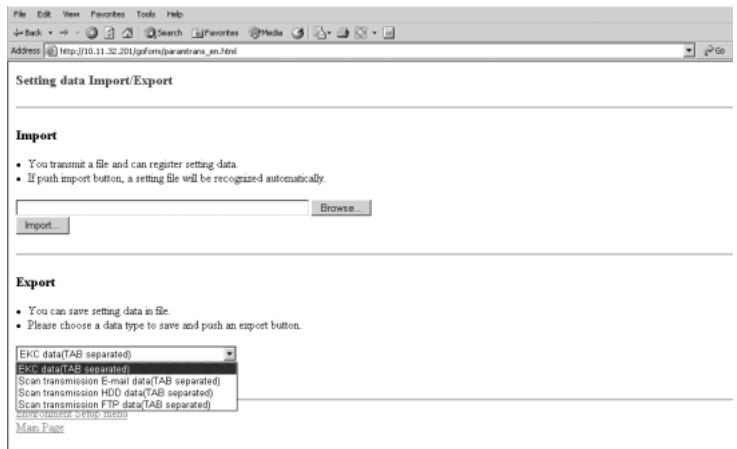
Select the desired file type from the pull-down menu, then click on [Export].

DETAILS
The data format cannot be changed from "TAB separated."
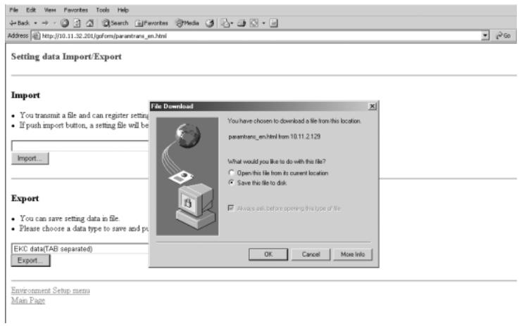
Confirm that the radio button heading "Save this file to disk" is marked in the File Download dialog box, then click on [OK] .
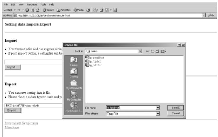
In the dialog box, designate the folder for saving the machine setting file, then click on [Save].

DETAILS
The file name is automatically assigned as described below. Select the data to be exported, changing the name if desired.
- ekc_tab.txt (E.K.C. data)
- ip_email.txt (E-mail data of Scan Transmission Setting data)
- ip_hdd.txt (HDD data of Scan Transmission Setting data)
- ipftp.txt (FTP data of Scan Transmission Setting data)

DETAILS: Error Message
The file cannot be accessed when the machine is operating. If an error message is displayed, try again to save the file after the current machine operation is completed.
A dialog box will be displayed when the saving operation is completed.
Click on [Close].
5. Edit the machine setting file.
The machine setting file transmitted to a PC is a TAB separated text file which can be edited using an application software such as Text Editor or Table Editor. A new setting file can also be created according to the specifications for each file type. See p. 10-57 to p. 10-58 for details.
6. Import the machine setting file.
Click on [Browse] to designate the machine setting file to be imported, then click on [Import].
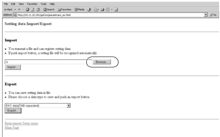
The result message will be displayed when the registration is completed.
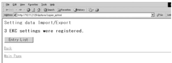

DETAILS: Error Message
If the registration cannot be completed successfully, error messages will be displayed as follows.
- Can't transfer data (The machine is busy) Try again to import the data after the machine operation in progress is completed.
- The data cannot be recognized Confirm that the data is the machine setting file.
- Data size is too large Confirm that the data is the machine setting file. Check if the file size exceeds 100,000 bytes.
- The data cannot be registered Check if inappropriate description is made in the machine setting file. See p. 10-57 to p. 10-58 for details. Check if the file entries are already over the limit.

DETAILS: To Edit the Machine Setting File
- Save the file as a text.
- Begin the file with a specified tag. (ex. #EKC_TAB)
A line should be 300 bytes or less. - The file size should be 100,000 bytes or less.
- The line that begins with "#" is a comment.
ex. Machine setting file of an E.K.C. data
#EKC TAB
passwordNAME LIMIT
00003636 ---ADMIN 100000
00000001 1 100000
00008156 ----KEN 000010
00000123 ----AAA 100000
12345678 A 001000
00000120 ----AAAA 010000
00003636 000000
36363636 -ADADMIN 100000
12341234 ---HOHO 100000
20202020 ----HAHA 200000
30303030 ----HEHE 300000
40404040 ----WAWA 000100
00000023 ----ICHI 100000
00012345 ---HORI 200000
12121212 ---KAKI 300000

DETAILS: Specifications for Each Machine Setting File Type
E.K.C. data setting file:
- Begin the file with #EKC_TAB.
Max. 1,000 files can be edited. - A line should include PASSWORD, NAME, and LIMIT, separated by a tab.
- Use up to 8 digits numbers (0 - 9) only to specify PASSWORD.
- Use numbers, alphabets (capital letters only), and four symbols: (· ,·) - and / only to specify NAME.
- Use up to 6 digits numbers (0 - 9) only to specify LIMIT (0 - 999,999).
E-mail data setting file:
- Begin the file with #IP_EMAIL.
Max. 1,008 files can be edited. - The second line starts with #GROUP NAME, if using grouping function, followed by max. 12 group names from 5th to 16th column.
GROUP NAME should be 18 bytes or less. - The third line (if using grouping function) should include NAME, ADDRESS, KANA, and DAILY USE, being separated by a tab.
NAME should be 18 bytes or less. - KANA (same as NAME) should be 18 bytes or less.
-
ADDRESS should be 200 bytes or less.
-
Mark DAILY USE and a group name with "1" in each column, if necessary.
- A group can include max. 2,045 bytes of e-mail address of the members.
- A group should include at least one user.
ex. Machine setting file of E-mail data
| #IP_EMAIL | ||||||
| #GROUP_NAME | test | sample | MyGroup month | |||
| #NAME | ADDRESS | KANA | DAILY USE | |||
| abcdefg | xxyyyzz@email.co.jp | abcdefg | ||||
| Akita | Akita | Akita | ||||
| alpha | a@a | alpha | 1 | |||
| Aomori | Aomori | Aomori | ||||
| April | April | April | 1 | 1 | ||
| August | August | August | 1 | 1 | ||
| baby | baby | baby | ||||
| beta | b@b | beta | 1 | |||
| Dedouja | Dedouja | Dedouja | ||||
| Februaray | Februaray | Februaray | 1 | |||
| GameGoy | GameGoy | GameGoy | ||||
| gamma | c@c | gamma | 1 | |||
HDD data setting file:
- Begin the file name with #IP_HDD.
Max. 48 files can be edited. - A line should include ENTRY NAME and BOX NUMBER, being separated by a tab.
- ENTRY NAME should be 18 bytes or less.
- Use up to 4 digits numbers (0 - 9) only to specify a BOX NUMBER.
FTP data setting file:
- Begin the file name with #IP FTP.
Max. 48 files can be edited. - A line should include PROFILE NAME, HOST ADDRESS, FILE PATH, LOGIN, and PASSWORD, being separated by a tab.
- PROFILE NAME should be 18 bytes or less.
- HOST ADDRESS should be 63 bytes or less.
- FILE PATH should be 96 bytes or less.
- LOGIN should be 47 bytes or less.
- PASSWORD should be 31 bytes or less.
SECTION
11
Paper and Original Information
Paper Information 11-2
Original Information 11-8
Paper
Information
Original
Information
11
Paper &
Original Info
This machine is equipped with the following trays for loading copy paper.
- Tray 1, 2, 3 and 4 (Main body tray)
LCT (LT-402/LT-412 Large Capacity Tray) - Multi-sheet bypass tray
Also, following equipments are provided for conveying/delivering copies.
- ADU (Automatic Duplex Unit)
- Finisher (FS-110/FS-111/FS-210)
- Cover sheet feeder (PI-110)
- Punching kit (PK-110/120/120 Type-A)
- Punching / Z-Folding unit (PZ-108/109)
- Shift tray (SF-101)
- Exit tray (for the machine without Finisher)
Refer to the following information on paper capacity for each.
Paper Weight
| Paper Trays | Weight |
| Tray 1 and 2 (service-fixed) Tray 3 and 4 (user-adjustable) (Main body tray) | 60 ~ 90 g/m² 91 ~ 200 g/m² for Thick paper 50 ~ 59 g/m² for Thin paper 91 ~ 170 g/m² for Tab paper |
| LCT (LT-402/LT-412) | |
| Multi-sheet bypass tray | |
| Equipments | Weight |
| ADU | 60 ~ 200 g/m² |
| Finisher | 50 ~ 200 g/m² 60 ~ 90 g/m² in Stitch&Fold / Fold mode 60 ~ 80 g/m² in Three-Fold mode |
| Cover sheet feeder | 50 ~ 200 g/m² |
| Punching kit | 50 ~ 170 g/m² |
| Punching / Z-Folding unit | 50 ~ 170 g/m² 60 ~ 90 g/m² in Z-Fold mode |
| Shift tray | 50 ~ 200 g/m² |
| Exit tray | 50 ~ 200 g/m² |

FOR DETAILS
- Some 170g / m^2 paper types may not be punched easily.
- The tray specified for Thin or Tab paper cannot be used for duplex copying.

HINTS
- See p. 13-23 for Paper Type setting of Tray 1, 2, 3, 4 or LCT.
See p. 3-29 for Paper Type setting of Multi-sheet bypass tray.
Tray/ Exit Tray Capacity
| Paper Trays | Capacity | |
| Tray 1 (Main body tray) | 1,500 sheets (80 g/m2) | |
| Tray 2 (Main body tray) | 1,000 sheets (80 g/m2) | |
| Tray 3 and 4 (Main body tray) | 500 sheets (80 g/m2) | |
| LCT (LT-402/LT-412) | 4,000 sheets (80 g/m2) | |
| Multi-sheet bypass tray | 100 sheets (80 g/m2) 1 sheet each for thick/thin paper and transparent film | |
| Equipments | Capacity | |
| ADU | Unlimited | |
| Finisher (FS-110/FS- 111/FS-210) | Secondary (sub) tray | 200 sheets |
| Primary (main) tray | 500 sheets (A5, A5R) 3,000 sheets (FS-110: A4, A4R, B5R, 8.5"x11", 8.5"x11"R) 2,500 sheets (FS-210: A4, A4R, B5R, 8.5"x11", 8.5"x11"R) 1,500 sheets (A3, F4, B4) 1,000 sheets* (Staple-sort mode) *See the following table. | |
| Finisher (FS-210) | Booklet tray | 100 sheets (A3, B4, 11"x17", 8.5"x14" in Fold/ Stitch&Fold mode) Fold: 33 sets for 3-sheet-folded booklet (99 sheets, 396 pages) Stitch&Fold: 20 sets for 5-sheet-folded book- let (100 sheets, 400 pages) 75 sheets (A4R, 8.5"x11"R in Fold/ Stitch&Fold mode) Fold: 25 sets for 3-sheet-folded booklet (75 sheets, 300 pages) Stitch&Fold: 15 sets for 5-sheet-folded book- let (75 sheets, 300 pages) 50 sheets (1 folded sheet in Three-Fold mode) |
| Cover sheet feeder (2 trays) | 200 sheets (200 g/m2) for each | |
| Punching kit | Unlimited | |
| Punching / Z-Folding unit | Punch: Unlimited Z-Fold: 1 sheet only See the table on the next page for using Staple-sort with Z-Fold mode. | |
Paper Information
Original Information

Paper & Original Info
| Equipments | Capacity |
| Shift tray | 500 sheets (A3, F4, B4, A5, 11"x17", 8.5"x14") 1,250 sheets (A4, A4R, B5, B5R, 8.5"x11", 8.5"x11"R) 100 sheets (A5R, A6R, 5.5"x8.5", 5.5"x8.5"R) |
| Exit tray | 150 sheets |
Paper Capacity for Staple-sort mode of FS-110/111/210 Finisher
| Paper size No. of copies | A3, 11"x17" | A5, 5.5"x8.5" | B4, F4, A4R, A4, B5, 8.5"x14", 8.5"x11", 8.5"x11"R |
| 2~9 | 50 sets | 50 sets | 100 sets |
| 10~20 | 50 | 50 | 50 |
| 21~30 | 30 | 30 | 30 |
| 31~40 | 25 | 25 | 25 |
| 41~50 | 20 | 20 | 20 |
| 51~60* | - | 15 | 15 |
| 61~100* | - | 10 | 10 |
*: FS-111 Finisher only
Capacity for Mixed Size Originals using Z-Fold and Staple-Sort
| Capacity for one stapled set | Primary Tray Capacity | |
| Number of Z-folded sheets | Number of regular sheets | |
| 1 sheet | 1 ~ 40 sheets | 20 stapled sets |
| 2 | 0 ~ 30 | 10 |
| 3 | 0 ~ 20 | 4 |
| 4 | 0 ~ 10 | 3 |
| 5 | 0 | 2 |
| 6 or more | Staple-Sort is unavailable with Z-Fold. | |
Paper Size
| Paper Trays | Available Sizes |
| Tray 1 and 2 (Main body tray) | A4 fixed (can be changed to B5, A5, 8.5"x11" or 5.5"x8.5") |
| Tray 3 and 4 (Main body tray) | STD size: A3, B4, F4, A4, A4R, B5, B5R, A5*, 11"x17", 8.5"x14", 8.5"x11"*Portrait orientation only.STD (special): Detects 8.5"x11"R instead of A4R, 5.5"x8.5" instead of A5.Non STD size: Max. 314 mm x 459 mm ~ Min. 210 mm x 140 mm Wide size: A3W, B4W, F4W, A4W, A4WR, B5W, A5W, 11"x17"W, 8.5"x11"W, 5.5"x8.5"W |
| LCT (LT-402) | A4 fixed (can be changed to the following sizes)STD size: B5, 8.5"x11"*Non STD size: Max. 314 mm x 223 mm ~ Min. 257 mm x 182 mm Wide size: A4W, B5W, 8.5"x11"W |
| LCT (LT-412) | A3 fixed (can be changed to the following sizes)STD size: B4, F4, A4, A4R, 11"x17", 8.5"x14", 8.5"x11", 8.5"x11*RNon STD size: Max. 314 mm x 459 mm ~ Min. 257 mm x 210 mm Wide size: A3W, B4W, F4W, A4W, A4WR, B5W, A5W, 11"x17"W, 8.5"x11"W, 5.5"x8.5"W |
Paper Information
Original Information

Paper & Original Info

HINTS
- Main body trays 1 and 2 are initially fixed to A4. Contact your service representative to change the tray size, if desired.
-
Main body trays 3 and 4 are user-adjustable. See p. 2-34 to change the paper size of the tray. For special size setting, see p. 13-23 to p. 13-24.
-
LT-402 is initially fixed to A4, and LT-412 is fixed to A3. Contact your service representative to change the tray size, if desired.
| Paper Trays | Available Sizes |
| Multi-sheet bypass tray | STD size: A3, B4, F4, A4, A4R, B5, B5R, A5, A5R, A6R, 11"x17", 8.5"x11"STD (special): Detects 8.5"x11"R or F4 instead of A4R or 5.5"x8.5" instead of A5R.Non STD size: Max. 314 mm x 459 mm ~ Min. 100 mm x 148 mmWide size: A3W, B4W, F4W, A4W, A4WR, B5W, B5WR, A5W, A5WR, 11"x17"W, 8.5"x11"W, 8.5"x11"WR, 5.5"x8.5"W, 5.5"x8.5"WR |
| Equipments | Available Sizes |
| ADU | STD size / STD (special): A3 to A5* *Portrait orientation only. Non STD size: Unavailable Wide size: A3W to A5W* *Portrait orientation only. |
| Finisher | Max. 314 mm x 459 mm ~ Min. 100 mm x 148 mm A4R / 8.5"x11"R only in Three-Fold mode |
| Cover sheet feeder (upper tray) | A4, A4R, B5, B5R, A5, 8.5"x11", 8.5"x11"R, 5.5"x8.5" |
| Cover sheet feeder (lower tray) | Max. 314 mm x 459 mm to A5 |
| Punching kit | Max. 314 mm x 459 mm to A5 |
| Punching / Z-Folding unit | Punch mode: A3, B4, F4, A4, B5 Z-Fold mode: A3, B4 All other paper sizes will be output without Z-fold. |
| Shift tray | Offset/Straight output: A3, B4, F4, A4, A4R, B5, B5R, A5, A5R, 12"x18", 11"x17", 8.5"x14", 8.5"x11", 8.5"x11"R, 5.5"x8.5", 5.5"x8.5"R Straigt output only: A6R |
| Exit tray | Max. 314 mm x 459 mm ~ Min. 100 mm x 148 mm |

HINT
See p. 3-29 to p. 3-32 for specifying the special paper size of the Multi-sheet bypass tray.
Special Paper in Multi-Sheet Bypass Tray
Multi-sheet bypass tray accepts the following special paper type that cannot be loaded in the main body trays.
Transparent film, labels, hole punch, rag content

FOR DETAILS
When using special paper type other than the above mentioned, select "User" as the paper type in Paper type/size setting for the Multi-sheet bypass tray.
To Store Copy Paper
- Store paper in a cool, dry area. Using damp copy paper may cause a paper misfeed.
Keep partially used packages tightly wrapped during storage.
- Do not place paper packages vertically to store.
Paper curl due to the vertical storage may cause a paper misfeed.
Paper Information
Original Information
11
Paper & Original Info
Use the platen glass or document feeder to position originals to copy.
Platen Glass Originals
Use the platen glass when originals are not suitable for use with the document feeder, e.g., when size is incompatible, or when originals are folded, stapled, torn, or in generally poor condition.

HINT
See each description in this manual for copy conditions which cannot use the document feeder to scan.
Unsuitable RADF Originals
| 1 Curled, creased or folded originals | 2 Paste-ups or cut-outs | 3 Books |
| 4 Glossy or transparent originals, OHP film, art paper, cellophane | 5 Doubled, punched or stapled originals | 6 Thin or thick originals |
Platen Glass Original Specifications
Max. original size: A3, sheet or book
Max. book weight/thickness: 6.8 kg / 30 mm
Original placement: Face down on left depth side of glass

HINT
Detectable paper size can be changed from only A series to Inch series, AB series, or AB series and Inch series mixed by Key Operator. See p. 13-39 to p. 13-46.

CAUTION
Do not place too heavy originals, or do not press strongly when thick original is placed and is under pressure of RADF; otherwise the glass may be broken and you may be injured.
RADF Originals
Following three modes are provided when using the document feeder (RADF) to scan originals.
Normal mode
- Mixed Original mode
- Z-Folded Original mode
Specifications for each mode are described as follows.

HINT
Detectable paper size can be changed from only A series to Inch series, AB series, or AB series and Inch series mixed by Key Operator. See p. 13-39 to p. 13-46.
Normal mode
Detectable original size: A3, B4, F4, A4R, A4, B5R, B5, A5, A5R, 11"x17", 8.5"x11"R, 8"x13"
Original weight: 50 130g / m^2 (no special stock)
Max. feeder capacity: 100 sheets (80 g/m² paper)
Curling tolerance: 10 mm or less
Original placement: Face up
Mixed Original mode
Use Mixed Original mode to copy mixed size originals. See p. 8-8 for details.
- Original size: Three types of size combination are determined by the RADF guide width.
A3 in landscape / A4 in portrait orientation:
A3, B4, A4R, A4, B5, A5 mixed
B4 in landscape / B5 in portrait orientation:
B4, A4R, B5R, B5, A5 mixed
A4 in landscape / A5 in portrait orientation:
A4R, B5R, A5 mixed
Original weight: 50 130g / m^2 (no special stock)
Max. feeder capacity: 100 sheets (80 g/m² paper)
Curling tolerance: 10mm or less
Original placement: Face up (see p. 3-3 for details.)
Paper Information
Original Information

Paper & Original Info

FOR DETAILS
See below for the guide width of each combination.
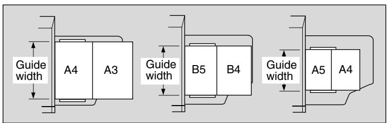
Z-Folded Original mode
Use Z-Folded Original mode to scan folded originals without using the size detection sensor of the RADF. See p. 8-10 for details.
Detectable original size: A3, B4, F4, A4R, A4, B5R, B5, A5, A5R, 11"x17", 8.5"x14", 8.5"x11"
Original weight: 50 130g / m^2 (no special stock)
Max. feeder capacity: 100 sheets (80 g/m² paper)
Curling tolerance: 10mm or less
Original placement: Face up; orientation same as copy paper
SECTION
12
Maintenance & Supplies
How to Maintain the Copier
Adding Toner 12-2
Inserting a New Staple Cartridge into FS-110/210 Finisher 12-5
Inserting a New Staple Cartridge into FS-111 Finisher 12-8
Empty Waste Basket of PK-110/120/120 Type-A Punching Kit....12-12
Empty Waste Basket of PZ-108/109 Punching / Z-Folding Unit...12-14
Cleaning Image Scanning Section 12-16
Checking Copy Count 12-18
Copy Materials 12-20
When toner supply is low, the message "Please add toner" and the ADD TONER icon (ADD TONER) display on the touch screen.
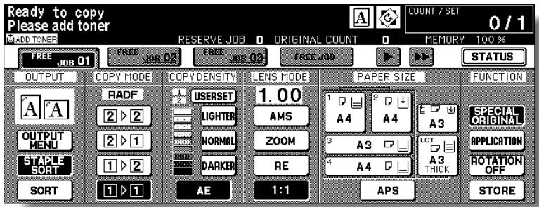

Please Be Reminded!
Use the toner cartridge of the same number as the number described on the label of a toner access door inner side, otherwise the machine trouble may occur.
Add toner according to the procedure as follows.
- Open the Toner access door.
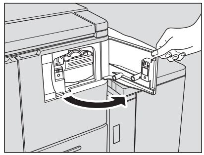
- Pull the Toner cartridge holder lever forward and withdraw the Toner cartridge holder.
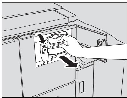
3. Remove the empty toner cartridge.
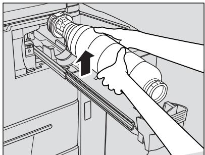
4. Shake the new Toner cartridge several times to loosen toner.
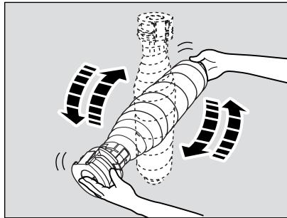
5. Remove the Toner cartridge cap.

6. Set the new Toner cartridge into the Toner cartridge holder.
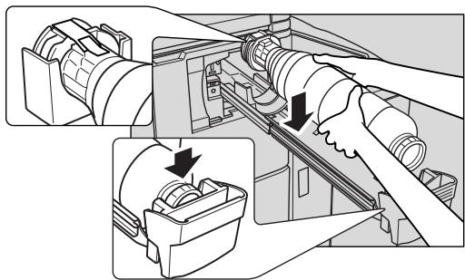

FOR DETAILS
Align the rear part of the Toner cartridge with the Toner cartridge holder.
7. Return the toner cartridge holder to its original position, then close the Toner access door securely.
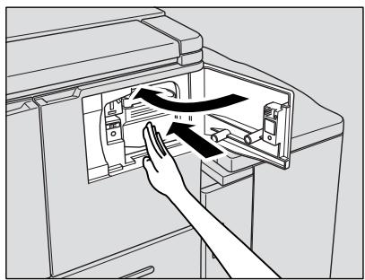
CAUTION
Keep the toner cartridge away from children. The toner is nontoxic; however if you inhale or contact with eyes by accident, flush with water and seek medical advice.
CAUTION
Do not throw the empty toner cartridge into a fire. If it is thrown into a fire, the toner may ignite and cause a dangerous situation.
Inserting a New Staple Cartridge into FS-110/210 Finisher
When the staple cartridge of the Finisher is empty, the Basic Screen displays the following message in the message area.
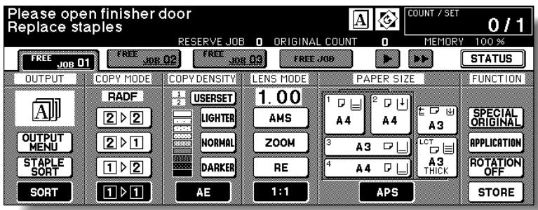
Follow the procedure below to replace the staple cartridge.

Please Be Reminded!
Use only the staples supplied by us. Please contact your service representative to purchase.
1. Open the Finisher door.
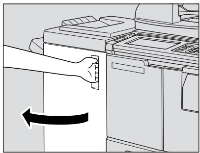
2. Pull out the stacker unit by holding the stacker unit handle.
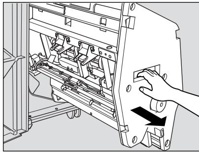
3. Pull up the cartridge housing, then remove it while sliding it along the stapler rail.
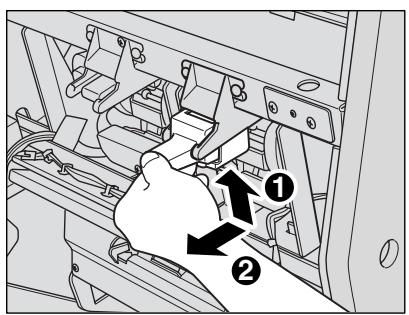
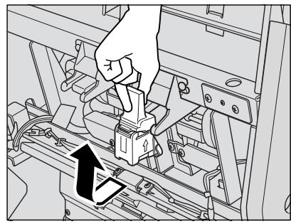
4. Remove the empty cartridge from the cartridge housing.
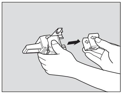
5. Insert the new cartridge into the housing.
Firmly insert the cartridge into the housing while aligning the arrow sides of both case and housing, then remove the lock tape from the cartridge.
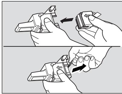

Please Be Reminded!
Do not remove the staples remaining inside the housing; otherwise, the first sheet output after the replenishment will not be stapled.
- Insert the cartridge housing while sliding it along the stapler rail, then push down and in to secure it in place.
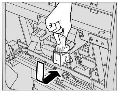
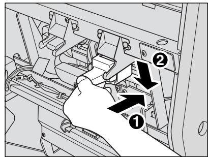
- Return the stacker unit to its original position.
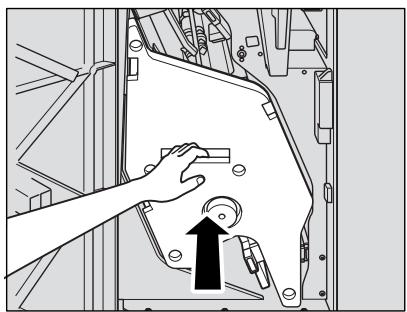
- Close the Finisher door.

Inserting a New Staple Cartridge into FS-111 Finisher
When the staple cartridge of the Finisher is empty, the Basic Screen displays the following message in the message area.
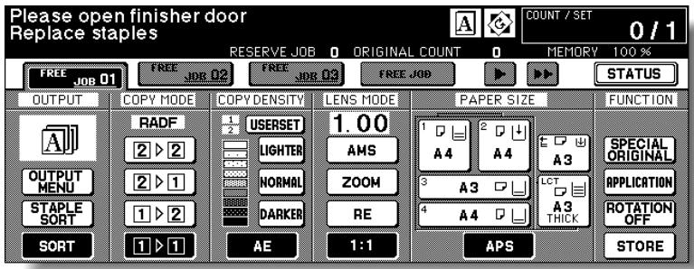
Follow the procedure below to replace the staple cartridge.

Please Be Reminded!
Use only the staples supplied by us. Please contact your service representative to purchase.
1. Open the Finisher door.
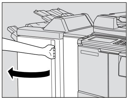
2. Pull out the stacker unit by holding the stacker unit handle.
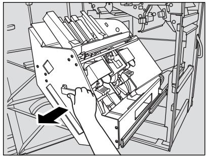
- Pull up the cartridge housing, then remove it while pulling it forward.
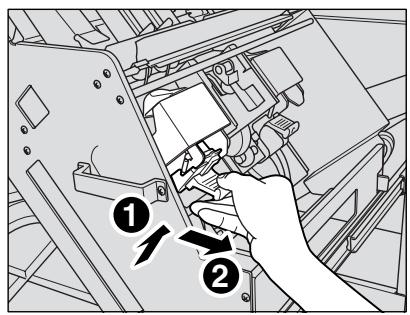
- Open the bottom of the cartridge housing while pressing two locks on both sides, then remove the empty cartridge from the cartridge housing.
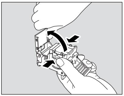
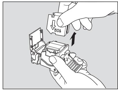
5. Insert the new cartridge into the housing.
Firmly insert the cartridge into the housing while aligning the arrow indication on the cartridge appears as shown below.
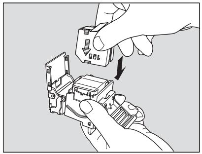

Please Be Reminded!
Do not remove the staples remaining inside the housing; otherwise, the first sheet output after the replenishment will not be stapled.
- Remove the lock tape from the cartridge, then close the bottom of the housing.
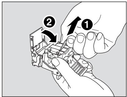
- Insert the cartridge housing, then push down and in to secure it in place.
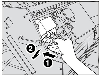
- Return the stacker unit to its original position.
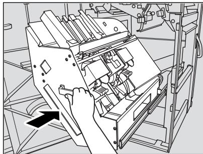
9. Close the Finisher door.
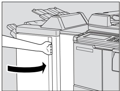
| Adding Toner |
| Inserting New Staple Cartridge |
| Empty Waste Basket |
| Cleaning Scanning Section |
| Checking Copy Count |
| Copy Materials |
| 12 Maintenance & Supplies |
Empty Waste Basket of PK-110/120/120 Type-A Punching Kit
When the waste basket becomes full, "Waste basket of Punching kit is full / Please empty waste basket" message will be displayed on the touch screen, and the finished set will be output without being punched even if Punch mode is selected.

Follow the procedure below to empty the waste basket.
1. Open the Finisher door.
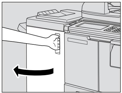
2. Withdraw the waste basket.
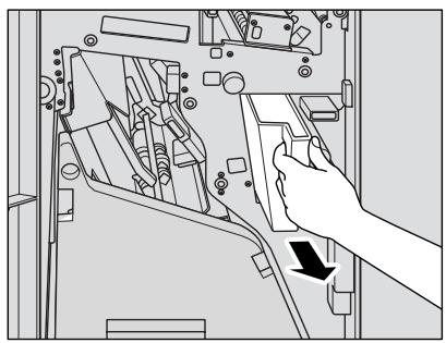
PK-110
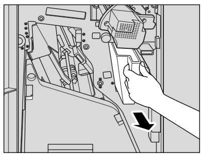
PK-120/120 Type-A
3. Empty the waste basket.
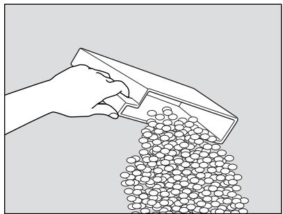
4. Return the waste basket to its original position, then close the Finisher door securely.
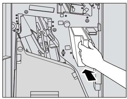
PK-110
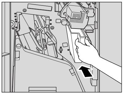
PK-120/120 Type-A
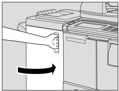
Empty Waste Basket of PZ-108/109 Punching / Z-Folding Unit
When the waste basket becomes full, "Waste basket of Punching unit is full / Please empty waste basket" message will be displayed on the touch screen, and the finished set will be output without being punched even if Punch mode is selected.
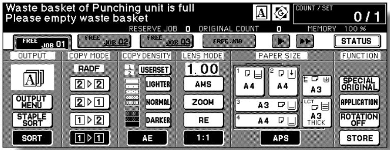
Follow the procedure below to empty the waste basket.
- Open the Punching / Z-Folding unit front door with the Finisher door handle.
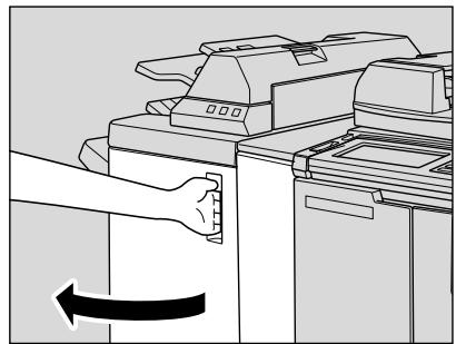
- Withdraw the waste basket.
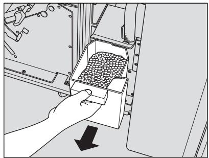
3. Empty the waste basket.
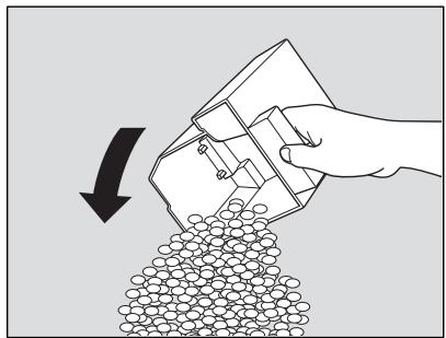
4. Return the waste basket to its original position, then close the Punching / Z-Folding unit front door securely.
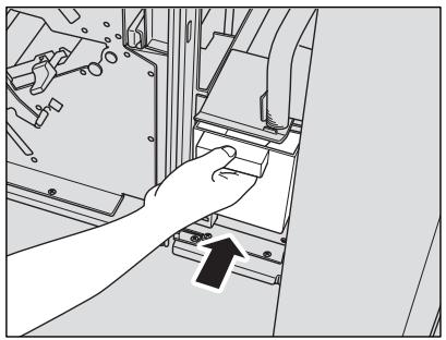
In order to maintain optimum copy quality, always keep the following areas clean.
Cleaning the Document Glass
Raise the document cover, and clean the glass with a clean soft cloth. The glass may also be cleaned with a soft cloth dampened slightly with water, if it is difficult to be cleaned.
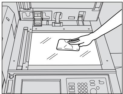

Please Be Reminded!
Never use paint solvents, such as benzene or thinners, to clean the platen glass.
Cleaning the Left Partition Glass
Keep the glass clean; otherwise soil marks may be copied, resulting in dark lines on the copies.
Raise the document cover, and clean the left partition glass with a clean soft cloth.
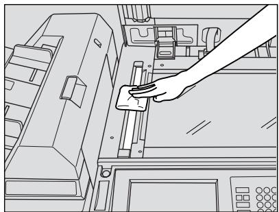
Cleaning the RADF Platen Guide Cover
The RADF platen guide cover should be kept clean; otherwise soil marks may be copied or the original size cannot be detected correctly.
Raise the document cover, and clean the RADF platen guide cover with a clean soft cloth.
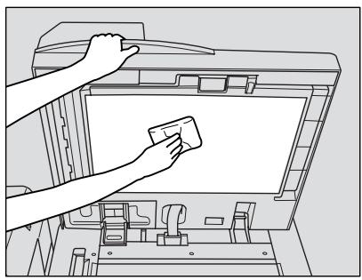

Please Be Reminded!
Never use paint solvents, such as benzene or thinners, to clean the RADF platen guide cover.
This function allows you to view the current indication of the following items as a list on the touch panel: Total counter, Copier counter, Printer counter, Counter start date.
Check the list, then print it from the Counter List Screen, if desired.
To Display the Counter List Screen
1. Press [P (COUNTER)] on the control panel.
![KONICA MINOLTA 7255 - Press [P (COUNTER)] on the control panel. - 1](/content/2025/01/139764/images/9b12dbdb55677f57fea7aa667b80755501d0e188cd0bc3c69b78fc2eb704be5b.jpg)
The Counter List Screen will be displayed.
![KONICA MINOLTA 7255 - Press [P (COUNTER)] on the control panel. - 2](/content/2025/01/139764/images/a6f7b995350a437871e177c8e821792789c2de833a540a8e256619bf9d8950cd.jpg)
2. Touch EXIT to return to the Basic Screen.
To Print the Counter List
- Press [P (COUNTER)] on the control panel.
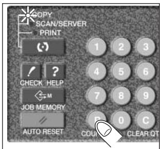
The Counter List Screen will be displayed.
- Touch COUNTER MENU.
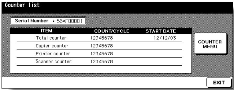
The Basic Screen will be displayed.
- Touch the desired tray key to select the copy size.
- Press [START].
The Counter list will be printed out, and the Management list mode will be released automatically.
Maintenance Kit
Developer 1
Charging corona plate 1
Charging wire 1
Charging cleaning board 1
Charger slide member 1
Charger cleaning block/Upper 1
Resin ring (D = 2mm) 3
(Charging, transfer/separation corona unit)
Charger cleaning block/Lower 1
Toner guide roller 1
Cleaning blade 1
Discharge wire 3
Transfer cleaning assembly 1
Separation cleaning assembly 1
Transfer presser rubber 3
Ozon filter M 1
Ozon filter S 1
Developing suction filter 1
Fixing web unit 1
Fixing claw/Upper 6
Cleaning pad (10 pcs.) 5
Polyethylene gloves 1
Dust bag (rubber band) 1
Developer collection sheet 1
(rubber band)
Hand case for collection 1
Cotton swabs (4 pcs.) 2
SECTION
13
Key Operator Mode
How to Monitor Copier Activity and Modify Machine Settings
How to Access the Key Operator Mode 13-2
[1] System Initial Setting 13-4
[2] Copier Initial Setting. 13-10
[3]User Setting Mode 13-12
[4] E.K.C. (Electronic Key Counter) Function Setting 13-15
[5] Lock/Delete Job Memory 13-22
[6] Paper Type / Special Size Set 13-23
[7] Panel Contrast / Key Sound Adjustment 13-25
[8] Key Operator Data Setting. 13-26
[9] Weekly Timer 13-27
[10] Control Panel Adjustment 13-36
[11] Tray Auto Select Setting 13-37
[12] Power Save Setting 13-38
[13] Memory Switch Setting 13-39
[14] Machine Management List Print 13-47
[15] Call Remote Centre 13-48
[16] Side 2 Lens Adjustment. 13-49
[17] Finisher Adjustment 13-50
[18] HDD Management Setting 13-52
[19] Scan Transmission Setting 13-54
[20] Non-Image Area Erase Setting 13-56
[21] Background Adjustment 13-57
[22] Timing Adjustment 13-58
[23] Centring Adjustment 13-60
How to Access the Key Operator Mode
The Key Operator is trained to handle all special Key Operator functions that are not accessible to the general user, such as monitoring overall copier activity, machine performance, and service information; modifying machine settings; and controlling user activity, for billing purposes.
A unique 4-digit Key Operator password is normally set by service at installation. If the unique code is not set by service, the copier will not display Key Operator Password Entry Screen when the Key Operator mode is being accessed, and a Key Operator password will not be required. A service-set 8-digit EKC master key code must be entered by the Key Operator to access the Electronic Key Counter functions, and a service-set 4-digit Weekly Timer master key code must be entered by the Key Operator to access the Weekly Timer functions.
To ensure the security of Key Operator mode, it is recommended that you establish a unique Key Operator password, along with the Key Operator EKC master key code and Weekly Timer master key code, and keep them in a confidential file.
To Display the Key Operator Mode Screen
- Press [HELP] on the control panel to display the Help Screen.
- Touch KEY OPERATOR MODE on the Help Screen.
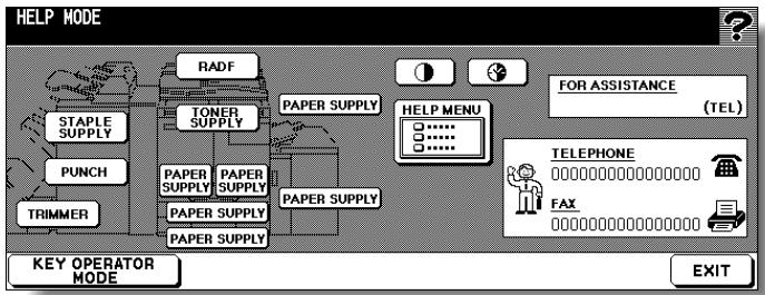
- Use the keypad on the touch screen to enter your 4-digit Key Operator password; then touch OK.
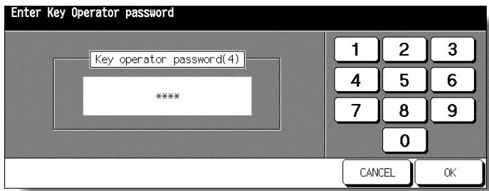

FOR DETAILS
If an invalid Key Operator password is entered, continue by entering the valid 4-digit password. If the Key Operator password is not valid, check with your service representative.
4. Make setting changes from the Key Operator Mode Screen, as described on the following pages.

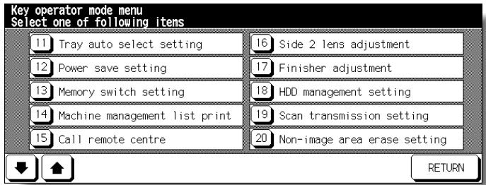
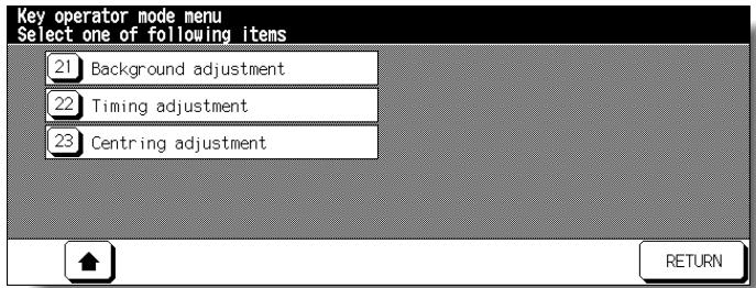

FOR DETAILS
-
To display menus [11] to [23] of the Key Operator Mode Screen, touch . To return the menu [1] to [10] of the Key Operator Mode Screen, touch .
-
The function number [15] Call remote centre on the Key Operator Mode Screen will be dimmed and cannot be selected on the copier without the remote diagnostics activated.
- Menus [22] and [23] are not initially provided on the screen. Contact your service representative, if desired.
5. Touch RETURN to exit the Key Operator mode.
The Basic Screen will be restored.
Set the following initial conditions of the copier.
- Date & Time setting: Current date and time, summer time
- Language select setting: Language used in LCD (English)
- IP address setting: IP address to be accessed from PC
- E-mail address setting: E-mail address to be informed of machine trouble or request for supplies.
[1] Date & Time Setting
Set the current date and time, the summer time, and also the time difference.
Default setting: Summer time off
![KONICA MINOLTA 7255 - [1] Date & Time Setting - 1](/content/2025/01/139764/images/0d5fb98bd58c7b3f0f6c9ada9690127cbd829e0071bd5032a6a716ed6f90a1b5.jpg)
System Initial Setting Menu Screen
![KONICA MINOLTA 7255 - [1] Date & Time Setting - 2](/content/2025/01/139764/images/5291b5fbd359d9aa6d8d205afa816f33f355647a5c0f8bc742ed31b1e903388a.jpg)
Date & Time Setting Screen
![KONICA MINOLTA 7255 - [1] Date & Time Setting - 3](/content/2025/01/139764/images/b3f28e1001656b2dfb8b2d40b0697c826107cd21a6f3343bcf022e1df378b72e.jpg)
Difference in Time Setting Screen
Procedure
1 Touch [1] System initial setting on the Key Operator Mode Screen to display the System Initial Setting Menu Screen.
2 Touch [1] Date & Time setting to display the Date & Time Setting Screen.
3 Adjust the time.
The time that the copier currently has is displayed in the upper line, in the order of date, month, year, and time (in 24-hour expression).
(1) Touch SET to move the highlighted section to the number to be changed.
(2) Use the keypad on the screen to enter the number.
4 To activate the summer time function, touch Summer time to highlight it. The Present time will gain an hour.
5 The Difference in time setting is provided in order to give the time difference information at the same time when E-mail is received.
To set this function, follow the procedure below.
(1) Touch Diff. time setting to display the Difference in Time Setting Screen.
(2) Touch + - to display “+” when the local time is earlier than the Universal time, or “-” when the local time is later.
(3) Use the keypad on the screen to enter the time difference between the Universal time and the local time in the machine setting area. (e.g. Enter “-0900” for 9 hours later than the Universal time.)
6 Touch OK to update the Present time by the Setting time and return to the System Initial Setting Menu Screen.
7 Touch RETURN to restore the Key Operator Mode Screen.
8 If no further changes are required, touch RETURN to restore the Basic Screen to perform copying operations.
[2] Language Select Setting
Select the language used in the LCD.
Default setting: English
![KONICA MINOLTA 7255 - [2] Language Select Setting - 1](/content/2025/01/139764/images/ae230194e83650c9e80157fa0ee6165ef50d3bac968f6fbea221de8b1191277a.jpg)
System Initial Setting Menu Screen
![KONICA MINOLTA 7255 - [2] Language Select Setting - 2](/content/2025/01/139764/images/37cf4e164d4c7cab84679778496c583e3b0bcd3c790dfdac4c9cb93c4220b916.jpg)
Language Selection Screen
Procedure
1 Touch [1] System initial setting on the Key Operator Mode Screen to display the System Initial Setting Menu Screen.
2 Touch [2] Language select setting to display the Language Selection Screen.
3 Select the desired language mode.
4 Touch OK to complete the setting and return to the System Initial Setting Menu Screen.
5 Touch RETURN to restore the Key Operator Mode Screen.
6 If no further changes are required, touch RETURN to restore the Basic Screen to perform copying operations.
[3] IP Address Setting
When using the server function, this setting is required to enable a PC to gain access to this machine.
NOTE:
Consult your network manager to perform this setting. Incorrect setting may cause a trouble with other network systems.
Setting options: IP address; Subnetmask; Gateway address; Line speed
System Initial Setting Menu Screen
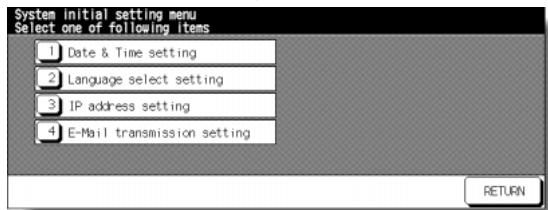
IP Address Setting Screen
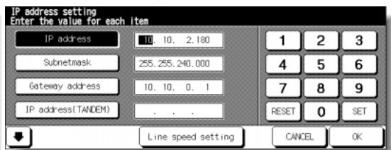
IP Address Setting Screen (next page)
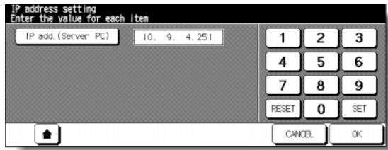
Line Speed Setting Screen
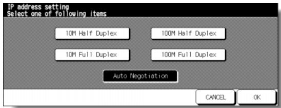
Procedure
1 Touch [1] System initial setting on the Key Operator Mode Screen to display the System Initial Setting Menu Screen.
2 Touch [3] IP address setting to display the IP Address Setting Screen.
3 Make the required setting.
Touch to highlight the address key on the left, then enter the address number using the screen keypad. Touch SET to fix the number, or touch RESET to clear.
4 When customizing the line speed, touch Line speed setting to display the Line Speed Setting Screen. Touch the desired key, then touch OK to restore the IP Address Setting Screen.
5 Touch OK to complete the setting and return to the System Initial Setting Menu Screen.
6 Touch RETURN to restore the Key Operator Mode Screen.
7 If no further changes are required, touch RETURN to restore the Basic Screen to perform copying operations.
[4] E-Mail Transmission Setting
When the machine requires troubleshooting or maintenance such as paper or toner supply, this setting allows several network PCs to be informed of the current machine status by E-mail.
The following information items are provided.
Service call
PM call
- Finisher tray full
JAM
-
Complete job
-
Dispose of trash basket
-
Paper supply
Non complete job
- Toner supply
Staple cartridge supply
NOTE:
Consult your network manager to perform this setting. Incorrect setting may cause a trouble with other network systems.
□ Setting options: IP address; E-Mail (machine manager); E-Mail (condition inform), E-Mail transmission item
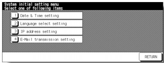
System Initial Setting Menu Screen
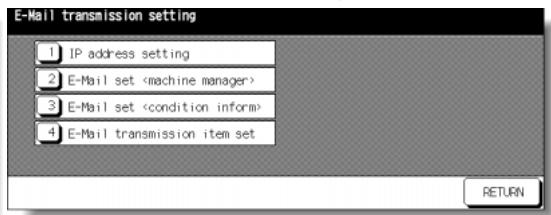
E-Mail Transmission Setting Screen
1 Touch [1] System initial setting to display the System Initial Setting Menu Screen, then touch [4] E-Mail Transmission Setting to display the E-Mail Transmission Setting Screen.
2 Touch [1] IP address setting to display the IP Address Setting Screen. Enter the IP address of the mail address in your network using screen keypad, then touch OK to restore the E-Mail Transmission Setting Screen.
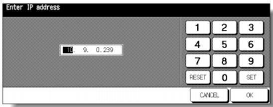
IP Address Setting Screen
3 Touch [2] E-Mail set (machine manager) to display the E-Mail Set (Machine Manager) Screen. Enter the E-mail address of the network manager using screen keypad, then touch OK to restore the E-Mail Transmission Setting Screen.

E-Mail Set (Machine Manager) Screen
4 Touch [3] E-Mail set (condition inform) to display the E-Mail Set (Condition Inform) Screen. Enter the E-mail address of the network PC using screen keypad, then touch OK to restore the E-Mail Transmission Setting Screen.
5 Touch [4] E-Mail transmission item set to display the Transmission Item Setting Screen. Touch to highlight the desired item key, then touch OK to restore the E-Mail Transmission Setting Screen.
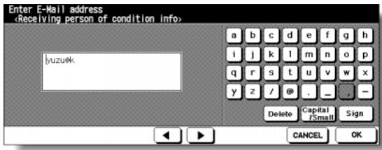
E-Mail Set (Condition Inform) Screen
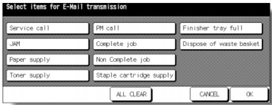
Transmission Item Setting Screen
6 Touch RETURN to complete the setting and return to the System Initial Setting Menu Screen.
7 Touch RETURN to restore the Key Operator Mode Screen.
8 Touch RETURN to return to the Basic Screen and perform copying operations.
Initial settings are the settings that display automatically when the copier is powered on, when Auto Reset timer is operated, or when [AUTO RESET] key is pressed. These settings can be changed by the Key Operator, as shown in this section.
Initially, i.e., at installation, the Basic Screen displays the following condition to meet Energy Star requirements:
Initial Setting
| Copy Mode : 1-1 |
| Copy Density : AE |
| Lens Mode : 1:1 |
| Paper Tray : APS |
| Output Mode : offset sort |
When Initial settings are changed by the Key Operator, the new initial settings display when the copier is powered on, when Auto/Reset timer is reached, or when [AUTO RESET] key is pressed.
The following initial settings can be changed by the Key Operator:
| Copy mode | : [RADF; 1-1; 1-2; 2-2; 2-1] |
| Copy density | : [AE; manual] |
| Lens mode | : [AMS; ratio 0.25~4.00] |
| Paper tray | : [APS; trays 1, 2, 3, 4, or LCT] |
| Output mode | : [Non-sort; Sort, Group; Staple-sort; Stitch&Fold; Fold; Punch; Z-fold; Three-fold; Cover sheet] |
| Special original | : [Original Direction; Duplex Binding; Text/Photo Enhance; Special Original; Original Form] |
| Rotation | : OFF |
Setting procedures are described on the following pages.
NOTE:
The most commonly-used settings are established at installation. Before changing any of the copier settings, be sure that you understand the overall and long-range effect of the change.

Key Operator Mode Screen
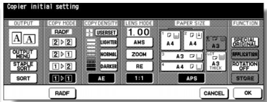
Copier Initial Setting Screen
Procedure
1 Touch [2] Copier Initial setting on the Key Operator Mode Screen to display the Copier Initial Setting Screen.
2 Make a selection for each mode as initial settings.
Touch RADF to select or deselect it.
NOTE:
The machine will restore the initial settings specified as above unless the Memory switch No. 4 "JOB memory (30) auto recall" is turned ON with the Job memory No. 30 registered.
3 Touch OK to complete the setting and return to the Key Operator Mode Screen.
4 If no further changes are required, touch RETURN to restore the Basic Screen to perform copying operations.
Set two userset density levels and three USERSETs of magnification.
[1] User Density Level 1 Setting
Output copying samples from 16 density levels from Lighter to Normal or Normal to Darker, then select the desired exposure and program it as USER1.
The programmed copy density can be recalled by selecting USER1 on the Basic Screen.
User Setting Mode Menu Screen

User Density Level 1 Setting Screen
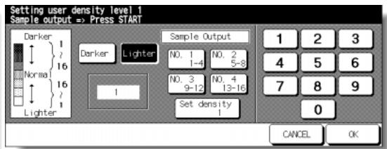
Procedure
1 Touch [3] User setting mode on the Key Operator Mode Screen to display the User Setting Mode Menu Screen.
2 Touch [1] User density level 1 setting to display the User Density Level 1 Setting Screen.
3 Place the original on the platen glass or in the RADF.
4 Touch Darker or Lighter to select the density level to be programmed.
5 Touch No.1 1~4, No.2 5~8, No.3 9~12, No.4 13~16, or Set density ##, then press [START]. The density level sample sheet will be output.
6 Select the desired exposure from the sample sheet(s), then enter the density level No. by using the touch screen keypad.
7 Touch OK to complete the setting and return to the User Setting Mode Menu Screen.
8 Touch RETURN to restore the Key Operator Mode Screen.
9 If no further changes are required, touch RETURN to restore the Basic Screen to perform copying operations.
[2] User Density Level 2 Setting
Output copying samples from 16 density levels from Lighter to Normal or Normal to Darker, then select the desired exposure and program it as USER2.
The programmed copy density can be recalled by selecting USER2 on the Basic Screen.
![KONICA MINOLTA 7255 - [2] User Density Level 2 Setting - 1](/content/2025/01/139764/images/924f5ef9a7d6cff89386ca8f0df9f63c2f65075861d6ad84f5d7eadf2ae6a338.jpg)
User Setting Mode Menu Screen
![KONICA MINOLTA 7255 - [2] User Density Level 2 Setting - 2](/content/2025/01/139764/images/d14b40fa6b9e72df845fba6929e0627ca8add829e4e8a7bcdc8542d5610093c1.jpg)
User Density Level 2 Setting Screen
Procedure
1 Touch [3] User setting mode on the Key Operator Mode Screen to display the User Setting Mode Menu Screen.
2 Touch [2] User density level 2 setting to display the User Density Level 2 Setting Screen.
3 Place the original on the platen glass.
4 Touch Darker or Lighter to select the density level to be programmed.
5 Touch No.1 1~4, No.2 5~8, No.3 9~12, No.4 13~16, or Set density ##, then press [START]. The density level sample sheet will be output.
6 Select the desired exposure from the sample sheet(s), then enter the density level No. by using the touch screen keypad.
7 Touch OK to complete the setting and return to the User Setting Mode Menu Screen.
8 Touch RETURN to restore the Key Operator Mode Screen.
9 If no further changes are required, touch RETURN to restore the Basic Screen to perform copying operations.
[3] User Lens Mode Ratio Setting
The preset and userset ratios are used to reduce and enlarge the original image to accommodate copy paper size, and are available on the Basic Screen.
NOTE:
Normally, users are allowed to change the three USERSETs in the bottom line on the User Lens Mode Ratio Setting Screen. The preset keys in the top and middle lines can also be programmed in 2-5 DIPSW mode, however, it is recommended not to change them.
Setting options: 用户或 Preset ratio
Default setting:USERSET1:4.00
USERSET2:2.00
USERSET3:0.50
User Setting Mode Menu Screen
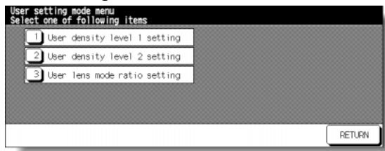
User Lens Mode Ratio Setting Screen
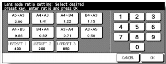
Procedure
1 Touch [3] User setting mode on the Key Operator Mode Screen to display the User Setting Mode Menu Screen.
2 Touch [3] User lens mode ratio setting to display the User Lens Mode Ratio Setting Screen.
3 Touch the USERSET you want to change, then enter a ratio from 0.25~4.00, using the keypad.
If a ratio under 0.25 is entered, 0.25 will be displayed.
If a ratio over 4.00 is entered, 4.00 will be displayed.
4 Touch OK to complete the setting and return to the User Setting Mode Menu Screen.
5 Touch RETURN to restore the Key Operator Mode Screen.
6 If no further changes are required, touch RETURN to restore the Basic Screen to perform copying operations.
[4] E.K.C. (Electronic Key Counter) Function Setting
This function can only be accessed by the Key Operator after a 8-digit EKC master key code is entered. The Electronic Key Counter allows you to monitor all copying activity by controlling EKC password accounts.
This feature can track copier usage for individual users and/or accounts as well as limit access to the copier to authorized users. Copy quantity limits for specific accounts can also be set. Use the EKC Key Operator Form provided at the end of this section to record EKC password information.
The EKC stores up to 1,000 EKC passwords, each of which represents a separate account that can be used for billing and recordkeeping. The number of users assigned to each account may depend upon the billing system in operation and the number of individuals and departments using the copier. When the EKC is activated, copying can be performed only after a valid EKC password is entered.
Copy quantity and copy limit for each account can be visually confirmed on the screen.
If EKC needs to be activated on your machine, contact your service representative.
The following EKC settings can be made:
[1] E.K.C. data edit:
Change, add, or delete EKC data, and reset the copy count of the individual account.
[2] E.K.C. all count reset:
Clear the copy count for all accounts.
[3] E.K.C. function setting:
Turn the EKC function on or off, and set conditions to stop immediately, stop after job is completed or display a warning message when copy limit is reached.
How to Access the EKC Setting Mode
Key Operator Mode Screen
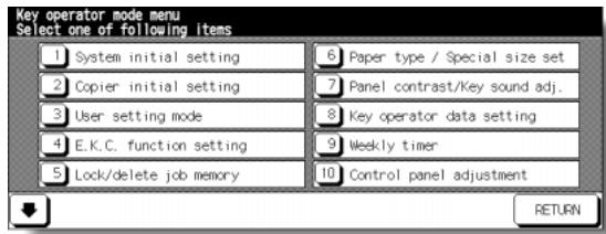
EKC Master Key Code Screen

EKC Setting Menu Screen
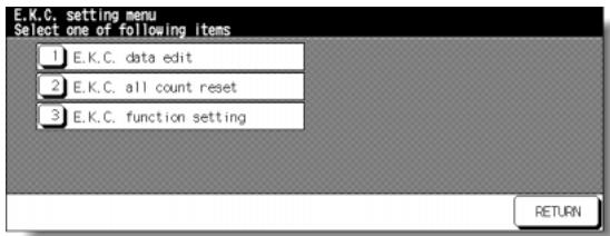
Procedure
1 Touch [4] E.K.C. function setting on the Key Operator Mode Screen. The EKC Master Key Code Screen displays, if a code is required.
2 Use the keypad on the touch screen to enter your 8-digit EKC master key code, then touch OK to display the EKC Setting Menu Screen. (See note.)
3 Select the desired EKC function, and make settings, as required. To exit the EKC mode, touch RETURN on the EKC Setting Menu Screen.
4 To exit the Key Operator mode, touch RETURN on the Key Operator Mode Screen to restore the Basic Screen.
NOTE:
If an invalid EKC master key code is entered, continue by entering the valid 8-digit code. The EKC master key code can be set to less than 8 digits by the Memory switch setting of the Key Operator function.
[1] E.K.C. Data Edit
Use this setting to display the list of copy count and copy limit for each account, to change, add, or delete the EKC data, and to reset the copy count of the individual account.
EKC No.: Designated by Key Operator
EKC Password: Unique 8-digit numeric code programmed by Key Operator for user
- User Name: Max. 8 characters
Copy Limit: 0 to 999,999 copies
EKC Setting Menu Screen
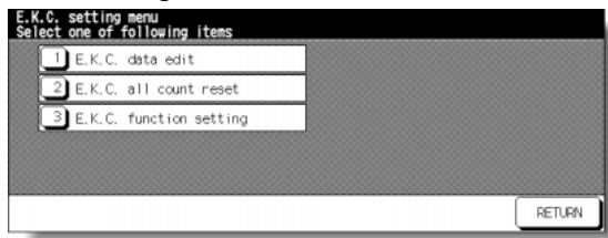
EKC Data Edit Screen
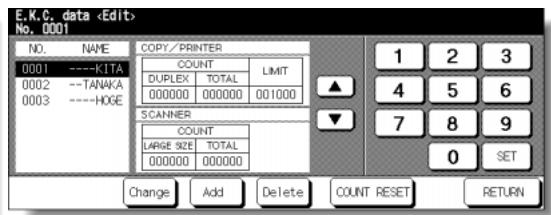
EKC Data Change Screen
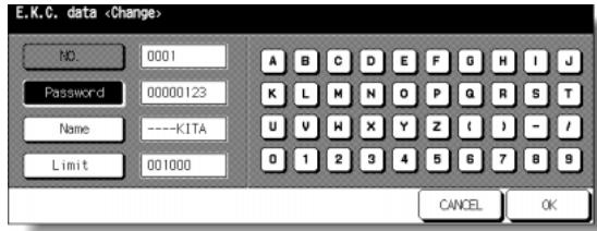
EKC Data Add Screen
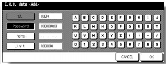
Password Duplication Screen
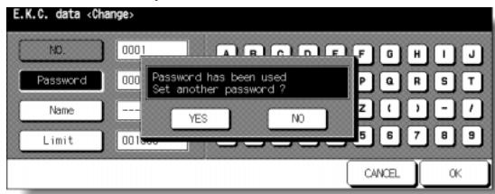
Name Duplication Screen
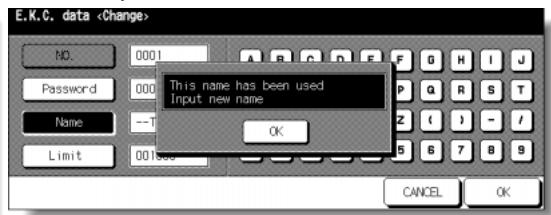
Procedure
1 Touch [4] E.K.C. function setting on the Key Operator Mode Screen. Enter an 8-digit EKC master key code, then touch OK to display the EKC Setting Menu Screen.
NOTE:
If an invalid EKC master key code is entered, continue by entering the valid 8-digit code.
2 Touch [1] E.K.C. data edit. The EKC Data Edit Screen will be displayed.
3 To change, add, or delete the EKC data, and to reset the copy count of the individual account, follow the procedure for each as described below.
To Change EKC Data:
(1) Touch or key on the right side of the list to highlight the EKC data to be changed, then touch Change. The EKC Data Change Screen will be displayed.
(2) Touch the desired item key to highlight it, then enter new data by using the touch screen keypad.
Password: 8 digits max. (See note 1.)
Name: 8 characters max. (See note 2.)
Limit: 999,999 copies max.
NOTES:
1 We recommend that you make a list of all EKC passwords and account numbers.
2 If an invalid user name is entered, continue by the valid name.
(3) Touch OK to complete the setting and to verify whether the same password or name has been already used for another account No.
When a password is duplicated:
The Password Duplication Screen will be displayed. Touch YES to re-enter new password, or NO to create duplicate password.
NOTE:
If duplicate password is created, the number of copies will be counted only for the EKC password with the smallest number. We recommend you do not use duplicate EKC password.
When a name is duplicated:
The Name Duplication Screen will be displayed. Touch OK to re-enter new name.
To Add EKC Data:
(1) Touch Add on the EKC Data Edit Screen. The EKC Data Add Screen will be displayed.
(2) Touch the desired item key to highlight it, then enter the data by using the touch screen keypad.
Password: 8 digits max. (See note 1.)
Name: 8 characters max. (See note 2.)
Limit: 999,999 copies max.
NOTES:
1 We recommend that you make a list of all EKC passwords and account numbers.
2 If an invalid user name is entered, continue by the valid name.
(3) Touch OK to complete the setting and to verify whether the same password or name has been already used for another account No.
When a password is duplicated:
The Password Duplication Screen will be displayed. Touch YES to re-enter new password, or NO to create duplicate password.
NOTE:
If duplicate password is created, the number of copies will be counted only for the EKC password with the smallest No. We recommend you do not use duplicate EKC password.
When a name is duplicated:
The Name Duplication Screen will be displayed. Touch OK to re-enter new name.
To Delete EKC Data:
(1) Touch or key on the right side of the list to highlight the EKC data to be deleted, then touch Delete. The Delete Confirmation Screen will be displayed.
(2) Touch YES to delete, or NO to cancel.
To Clear EKC Count:
(1) Touch or key on the right side of the list to highlight the desired EKC data, then touch COUNT RESET. The Reset Confirmation Screen will be displayed.
(2) Touch COPY/PRINTER to clear the copy/print count, SCANNER to clear the scan count, or ALL to reset both counters of the selected EKC data. Touch CANCEL to cancel this function.
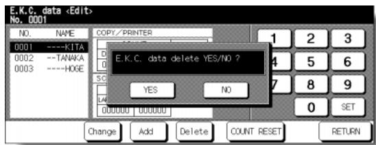
Delete Confirmation Screen
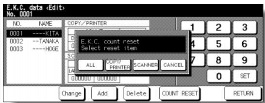
Reset Confirmation Screen
4 If other EKC setting changes are required, touch RETURN on the EKC Data Edit Screen to return to the EKC Setting Menu Screen. Touch desired key, from [1]~[3].
5 Touch RETURN to restore the Key Operator Mode Screen.
6 If no further changes are required, touch RETURN to restore the Basic Screen to perform copying operations.
[2] E.K.C. All Count Reset
Reset the count for all EKC accounts.
![KONICA MINOLTA 7255 - [2] E.K.C. All Count Reset - 1](/content/2025/01/139764/images/e0b22c03ca2cdc1347da4df43b14eca9c48eac70bc97f0bc4b6608e291a45489.jpg)
EKC Setting Menu Screen
![KONICA MINOLTA 7255 - [2] E.K.C. All Count Reset - 2](/content/2025/01/139764/images/0971120304661a33f81c4ee1f3c2c54d93a7bb4341c87baa8e563367d0e5988b.jpg)
EKC All Count Reset Screen
Procedure
1 Touch [4] E.K.C. function setting on the Key Operator Mode Screen. Enter an 8-digit EKC master key code, then touch OK to display the EKC Setting Menu Screen.
NOTE:
If an invalid EKC master key code is entered, continue by entering the valid 8-digit code.
2 Touch [2] E.K.C. all count reset. The EKC All Count Reset Screen will be displayed.
3 Touch COPY/PRINTER to clear the copy/printer count, SCANNER to clear the scan count, or ALL to reset all counters to zero and to return to the EKC Setting Menu Screen.
Touch CANCEL to restore the EKC Setting Menu Screen without resetting counters.
Touching RETURN will also cancel this function and return to the EKC Setting Menu Screen.
4 If other EKC setting changes are required, touch desired key, from [1]~[3].
5 Touch RETURN to restore the Key Operator Mode Screen.
6 If no further changes are required, touch RETURN to restore the Basic Screen to perform copying operations.
[3] E.K.C. Function Setting
Use this function to turn EKC On or Off and to select whether the copier/ printer and scanner will stop at the time the count limit is reached, or after the current copy job is completed.
![KONICA MINOLTA 7255 - [3] E.K.C. Function Setting - 1](/content/2025/01/139764/images/9e9a60fcdc94be0e8eadee81886aedb9a74018fc44bf70917bcff2c6553283b8.jpg)
EKC Setting Menu Screen
![KONICA MINOLTA 7255 - [3] E.K.C. Function Setting - 2](/content/2025/01/139764/images/7c9aa0e666d84bc3b55932d583bfddc327bb7a8131525806b62ae98297a9b3fb.jpg)
EKC Function Setting Screen
Procedure
1 Touch [4] E.K.C. function setting on the Key Operator Mode Screen. Enter an 8-digit EKC master key code, then touch OK to display the EKC Setting Menu Screen.
NOTE:
If an invalid EKC master key code is entered, continue by entering the valid 8-digit code.
2 Touch [3] E.K.C. function setting. The EKC Function Setting Screen will be displayed.
3 Touch EKC On to activate EKC or touch EKC Off to de-activate EKC individually for copier/printer and scanner.
The selected key will be highlighted.
4 Touch Immediately to stop the machine at once when the copy limit is reached. In this case, copy conditions selected for the current job will be cleared. To continue the job using the same user password, change the copy limit of the password or clear the copy count.
Touch After job to stop the machine after the current job is completed, when copy limit is reached.
Touch Warning only to display a warning message when copy limit is reached. The selected key will be highlighted.
5 Touch OK to complete the setting and return to the EKC Setting Menu Screen.
6 If other EKC setting changes are required, touch desired key, from [1]~[3].
7 Touch RETURN to restore the Key Operator Mode Screen.
8 If no further changes are required, touch RETURN to restore the Basic Screen to perform copying operations.
Use this function to lock/unlock or delete a Job that has been programmed.
A locked Job is indicated by a lock icon ( l ) on the Lock/Delete Job Memory Screen.
The settings of a locked job cannot be changed.
□ Setting options: Lock Job memory; Unlock Job memory; Delete Job memory
Lock/delete is available for all 30 stored jobs
Job lock is available only for named jobs
A blank key indicates that no job is programmed
*****************************************************************************************************
Key Operator Mode Screen
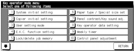
Lock/Delete Job Memory Screen
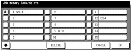
Procedure
1 Touch [5] Lock/delete job memory on the Key Operator Mode Screen to display the Lock/Delete Job Memory Screen.
2 To lock/unlock a job memory;
(1) Touch the key on the left side of the desired job number. Use arrow keys to scroll to the desired job number, if required.
(2) The lock icon will appear on the touched key to show that the selected job is locked. The previously locked job will be unlocked when selected, and the lock icon on the touched key will disappear.
To delete a job memory;
(1) Touch the job number you want to delete. Use arrow keys to scroll to the desired job number, if required.
(2) Touch DELETE. Selected programs and the name will be deleted from the job memory.
3 Touch OK to complete the setting and return to the Key Operator Mode Screen.
4 If no further changes are required, touch RETURN to restore the Basic Screen to perform copying operations.
[6] Paper Type / Special Size Set
Use this function to indicate a specific paper type or to specify a special paper size for each tray key on the Basic Screen. This is especially useful when special paper is used on a regular basis and is always placed in a specific paper tray.
NOTE:
The keys to specify the paper size of tray 1, 2, and LCT are not initially provided on the screen. Contact your service representative, if desired.
Key Operator Mode Screen

Paper Type Setting Screen
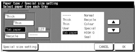
Special Size Setting Screen (STD size)
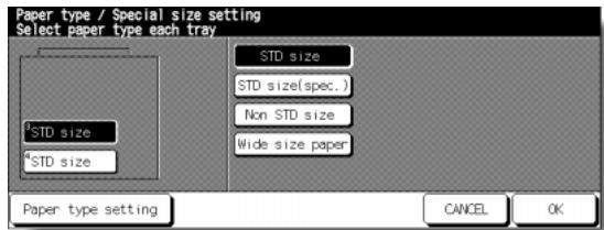
Special Size Setting Screen (STD size (special))
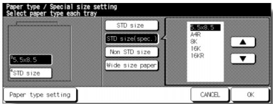
Special Size Setting Screen (Non STD size)
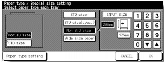
Special Size Setting Screen (Wide size (select))
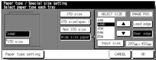
Special Size Setting Screen (Wide size (input)
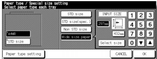
Procedure
1 Touch [6] Paper type / Special size set on the Key Operator Mode Screen to display the Paper Type Setting Screen.
2 To specify paper type;
(1) Touch the desired paper tray key to highlight it.
(2) Touch the arrow keys to select paper type.
To specify special size;
(1) Touch Special size setting on the Paper Type Setting Screen to display the Special Size Setting Screen.
(2) Touch the desired paper tray to highlight it.
(3) Touch a paper size key to specify a paper size for the selected tray.
- Select STD size to allow the machine to automatically detect the size of paper loaded in the tray and indicate it on the tray key.
- Select STD size (special) to display the popup menu to show available paper sizes to be specified. Use arrow keys on the popup menu to select the desired size.
- Select Non STD size to display the popup menu to enter the paper size by using arrow keys or touch screen keypad.
- Select Wide size paper to display the popup menu to show available wide paper sizes to be specified. Use arrow keys on the popup menu to select the desired wide size, then touch Input size to display the popup menu to enter the paper size by using arrow keys or touch screen keypad.
Touch Lead edge or Rear edge to select the image starting position.
3 Touch OK on the Paper Type Setting Screen or on the Special Size Setting Screen to complete the setting and return to the Key Operator Mode Screen.
4 If no further changes are required, touch RETURN to restore the Basic Screen to perform copying operations.
[7] Panel Contrast / Key Sound Adjustment
Use this feature to adjust the level of brightness of the touch screen portion of the control panel, and also the volume of the touch key.
Key Operator Mode Screen
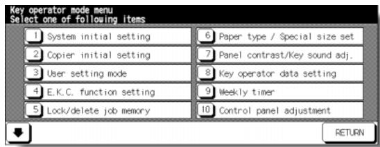
Panel Contrast/ Key Sound Adjustment Screen
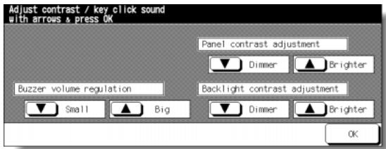
Procedure
1 Touch [7] Panel contrast/Key sound adj. on the Key Operator Mode Screen to display the Panel Contrast/ Key Sound Adjustment Screen.
2 Adjust the Panel contrast, Backlight contrast, or Buzzer volume, as desired.
Touch Dimmer to make the panel or backlight contrast dimmer than currently displayed, or touch Brighter to make the panel or backlight contrast brighter than currently displayed.
Touch Small or Big to regulate the buzzer volume of the touch keys.
3 Touch OK to complete the setting and return to the Key Operator Mode Screen.
4 If no further changes are required, touch RETURN to restore the Basic Screen to perform copying operations.
NOTE:
The control panel contrast feature can be adjusted from the Help screen. When the Control panel contrast key is pressed, the Contrast adjustment screen will be displayed.
Use this screen to enter the name and extension number of the Key Operator indicated on the Help Screen selected from the Basic Screen.
□ Setting options: 5-digit Key Operator telephone extension; Max. 8-character Key Operator name

Key Operator Mode Screen
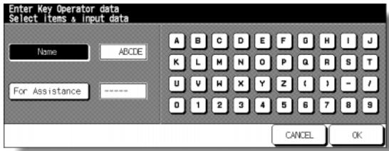
Key Operator Data Setting Screen
Procedure
1 Touch [8] Key operator data setting on the Key Operator Mode Screen to display the Key Operator Data Setting Screen.
2 Touch Name to highlight it, then enter the Key Operator name up to 8 characters from the touch screen keypad.
3 Touch Key Operator Tel. No. to highlight it, then enter a 5-digit extension number from the touch screen keypad.
If the extension number is less than 5 digits, use a hyphen [-] to make it five. The hyphen added in the beginning will be indicated as a space on the Help Screen.
4 Touch OK to complete the setting and return to the Key Operator Mode Screen.
5 If no further changes are required, touch RETURN to restore the Basic Screen to perform copying operations.
This function can be accessed only by the Key Operator after a unique 4-digit Weekly Timer master key code is entered.
The Weekly Timer is a copier management function that shuts down power to the machine on a daily or hourly basis, and can be programmed specifically for lunch breaks, weekends and holidays, or any time the copier is not required.
In Addition, Timer Interrupt can be enabled (with or without a password requirement) to allow temporary use of the machine during periods when power is shut down by the Timer function.
Conditions required to use the Weekly Timer:
- The power plug is inserted into the socket.
- The power switch is turned on.
- The current date and time are correctly set.
If the Weekly Timer needs to be activated on your machine, contact your service representative.
The following Weekly Timer settings can be made.
[1] Weekly timer ON/OFF setting
Enable and disable the Timer function.
[2] Timer Setting
Specify the times that the copier will turn ON and OFF for each day of the week or the entire week.
[3] Timer action ON/OFF Setting
Specify the working days of the machine by the Timer, for all Mondays through Sundays, and/or individually for each day of the given month.
[4] Lunch hour off setting
Specify the lunch time interval during which the copier will go off and on.
[5] Timer interrupt password set
Require Password entry for the Timer off function and establish the amount of usage time.
NOTES:
1 The time is set in terms of the 24 hour clock, where hour [1] is the first hour after midnight; and hour [24] is the hour of midnight. For example, 6 a.m. is 06:00 hours; 6 p.m. is 18:00 hours.
2 The [AUTO RESET] key is used to change numbers determined by the SET touch key.
How to Access the Weekly Timer Setting Mode
Key Operator Mode Screen

Weekly Timer Master Key Code Screen
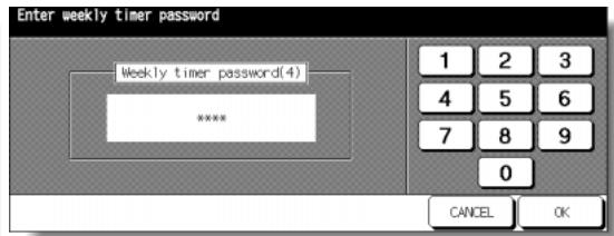
Weekly Timer Setting Menu Screen
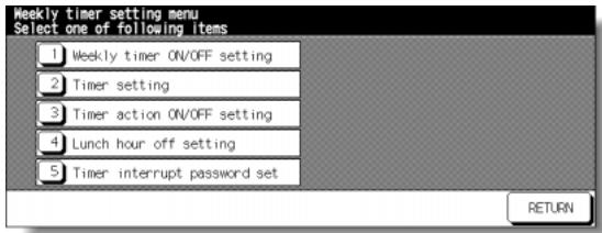
Procedure
1 Touch [9] Weekly timer on the Key Operator Mode Screen.
The Weekly Timer Master Key Code Screen displays when the 4-digit Weekly Timer master key code is set by service.
Otherwise, the Weekly Timer Setting Menu Screen displays without the code requirement.
2 If the Weekly Timer Master Key Code Screen is displayed, use the keypad on the touch screen to enter your 4-digit Weekly Timer master key code, then touch OK to display the Weekly Timer Setting Menu Screen.
NOTE:
If an invalid Weekly Timer master key code is entered, continue by entering the valid 4-digit code.
3 Select the desired Weekly Timer function, and make settings, as required.
4 To exit the Weekly Timer mode, touch RETURN on the Weekly Timer Setting Menu Screen.
5 To exit the Key Operator mode, touch RETURN on the Key Operator Mode Screen to restore the Basic Screen.
[1] Weekly Timer On/Off Setting
![KONICA MINOLTA 7255 - [1] Weekly Timer On/Off Setting - 1](/content/2025/01/139764/images/dfc98350805a06629679932b8a5ca8af2cf05a11fda1f67172880bf3ced749dd.jpg)
Weekly Timer Setting Menu Screen
![KONICA MINOLTA 7255 - [1] Weekly Timer On/Off Setting - 2](/content/2025/01/139764/images/c3f591df8c4965ddf33b156582c4a87f2485f1663786088db6d104395bf1468e.jpg)
Weekly Timer On/Off Setting Screen
Procedure
1 Touch [9] Weekly timer on the Key Operator Mode Screen. Enter your 4-digit Weekly Timer master key code, then touch OK to display the Weekly Timer Setting Menu Screen.
NOTE:
If an invalid Weekly Timer master key code is entered, continue by entering the valid 4-digit code.
2 Touch [1] Weekly timer ON/OFF setting to display the Weekly Timer On/Off Setting Screen.
3 Touch Weekly timer On to activate Weekly Timer, or touch Weekly timer Off to de-activate Weekly Timer. The default setting is Weekly timer Off. The selected key will be highlighted.
4 Touch OK to complete the setting and return to the Weekly Timer Setting Menu Screen.
5 Touch RETURN to restore the Key Operator Mode Screen.
6 If no further changes are required, touch RETURN to restore the Basic Screen to perform copying operations.
[2] Timer Setting
Use this function to set the On/Off times in hours and minutes for each day of the week or set the block time for the entire week, i.e., the same On/Off time for each day.
![KONICA MINOLTA 7255 - [2] Timer Setting - 1](/content/2025/01/139764/images/bfccfca38f3507a34a6b54133ef3f0d05aaf01a8ab3073a71a2410393e438ae0.jpg)
Weekly Timer Setting Menu Screen
![KONICA MINOLTA 7255 - [2] Timer Setting - 2](/content/2025/01/139764/images/81bf6a7a4e7b32be2db4f4b1c60b1d6be0c0ac0c7e5b1da789979c45aa72f325.jpg)
Weekly Timer On/Off Time Setting Screen
![KONICA MINOLTA 7255 - [2] Timer Setting - 3](/content/2025/01/139764/images/8bd7a79df8fc477bb05396d503531c012b3274ecbcf233bc747d161e3d459de3.jpg)
Weekly Timer On/Off Time Block Setting Screen
Procedure
1 Touch [9] Weekly timer on the Key Operator Mode Screen. Enter your 4-digit Weekly Timer master key code, then touch OK to display the Weekly Timer Setting Menu Screen.
NOTE:
If an invalid Weekly Timer master key code is entered, continue by entering the valid 4-digit code.
2 Touch [2] Timer setting to display the Weekly Timer On/Off Time Setting Screen.
3 When the screen is displayed, the ON-time of Monday is always highlighted. Enter a 2-digit ON-hour (ex. 8 a.m. is 08) and a 2-digit ON-minute (ex. 7 min. is 07) using the touch screen keypad, and then touch SET.
Touching SET repeatedly will shift the input section from Monday ON, Monday OFF, Tuesday ON, Tuesday OFF e.g.
NOTES:
- If ON-time and OFF-time are the same, power will not go on.
- If the setting is 00:00~00:00, you will not be able to set the copiers off/ on condition for specific days.
When setting Sunday OFF-time, Monday ON-time is highlighted again. Proceed to step 5.
4 To set the ON/OFF time collectively for more than one day of the week, touch Block set to display the Weekly Timer On/Off Time Block Setting Screen.
5 When you open this screen, the ON and OFF times are always set at 00:00~00:00. Touch to highlight the day(s) of the week to be set. More than one can be selected at a time.
Enter the ON-time and OFF-time using the touch screen keypad, and then touch SET after each entry.
6 Touch OK on the Weekly Timer On/Off Time Setting Screen or on the Weekly Timer On/Off Time Block Setting Screen to complete the setting, and return to the Weekly Timer Setting Menu Screen.
7 Touch RETURN to restore the Key Operator Mode Screen.
8 If no further changes are required, touch RETURN to restore the Basic Screen to perform copying operations.
[3] Timer Action On/Off Setting
Use this function to set the On/Off condition of the copier for a given month. Set the On-Off condition for specific days; or collectively, for all Mondays through Sundays of the given month. The default setting is collective: On for Mondays through Saturdays, and Off for Sundays.
Weekly Timer Setting Menu Screen
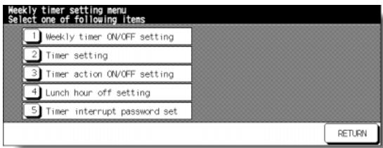
Timer Action On/Off Setting Screen
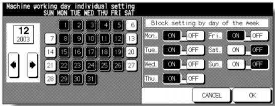
Timer Action Change Confirmation Screen
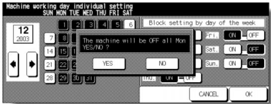
Procedure
1 Touch [9] Weekly timer on the Key Operator Mode Screen. Enter your 4-digit Weekly Timer master key code, then touch OK to display the Weekly Timer Setting Menu Screen.
NOTE:
If an invalid Weekly Timer master key code is entered, continue by entering the valid 4-digit code.
2 Touch [3] Timer action ON/OFF setting to display the Timer Action On/Off Setting Screen.
The days of the current month are displayed on the left half of the screen, with timer-active days highlighted.
3 To activate or deactivate the Timer for any individual day, touch the key for that day to change its indication.
To change the month, use arrows to scroll to the desired month.
4 To collectively set the on/off data for the entire month by the day of the week, touch the ON or OFF key for the desired day on the right half of the screen. If you touch an already-highlighted key, no change will occur.
5 If any change is made in the collective setting area, the Timer Action Change Confirmation Screen will be displayed.
Touch YES to change the timer action, or touch NO to cancel.
The Timer Action On/Off Setting Screen will be restored.
6 Touch OK on the Timer Action On/Off Setting Screen to complete the setting and return to the Weekly Timer Setting Menu Screen.
7 Touch RETURN to restore the Key Operator Mode Screen.
8 If no further changes are required, touch RETURN to restore the Basic Screen to perform copying operations.
[4] Lunch Hour Off Setting
The Weekly Timer function turns the copier ON and OFF once a day. Use this Lunch hour off function to shut down power for lunch break then turn on again while the copier is turned on due to the Weekly Timer function. The only one off time interval can be programmed.
Weekly Timer Setting Menu Screen

Lunch Hour Off Setting Screen
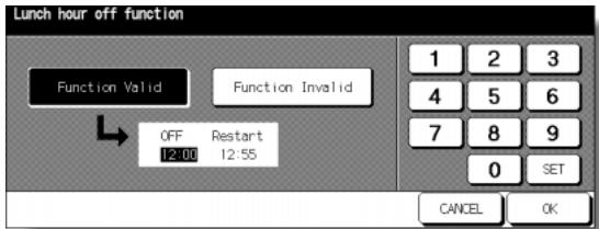
Procedure
1 Touch [9] Weekly timer on the Key Operator Mode Screen. Enter your 4-digit Weekly Timer master key code, then touch OK to display the Weekly Timer Setting Menu Screen.
NOTE:
If an invalid Weekly Timer master key code is entered, continue by entering the valid 4-digit code.
2 Touch [4] Lunch hour off setting to display the Lunch Hour Off Setting Screen.
3 Touch Function Valid to activate the Lunch hour off function.
Set OFF-time and Restart-time using the touch screen keypad, and then touch SET after each entry.
4 Touch Function Invalid to de-activate the Lunch hour off function. The time setting area will appear grayed out and cannot be selected.
The Function Invalid setting is the factory default setting.
5 Touch OK to complete the setting and return to the Weekly Timer Setting Menu Screen.
6 Touch RETURN to restore the Key Operator Mode Screen.
7 If no further changes are required, touch RETURN to restore the Basic Screen to perform copying operations.
[5] Timer Interrupt Password Setting
Use this password setting mode to establish a 4-digit password requirement for using Timer Interrupt function. The default password of 0000 allows the timer function to be interrupted without the requirement for password entry.
![KONICA MINOLTA 7255 - [5] Timer Interrupt Password Setting - 1](/content/2025/01/139764/images/c2b29224a3702ef369ad90b7c096e996488db9f5b5b4d181fa3156ee646e5fbf.jpg)
Weekly Timer Setting Menu Screen
![KONICA MINOLTA 7255 - [5] Timer Interrupt Password Setting - 2](/content/2025/01/139764/images/dd1289339ca392bce7d5e3f57b5762eaa30850d9b187e741f2dfc8b35a3fe6a0.jpg)
Timer Interrupt Password Setting Screen
Procedure
1 Touch [9] Weekly timer on the Key Operator Mode Screen. Enter your 4-digit Weekly Timer master key code, then touch OK to display the Weekly Timer Setting Menu Screen.
NOTE:
If an invalid Weekly Timer master key code is entered, continue by entering the valid 4-digit code.
2 Touch [5] Timer interrupt password set to display the Timer Interrupt Password Setting Screen.
3 Use the touch screen keypad to enter a 4-digit password, and then touch OK to complete the setting and return to the Weekly Timer Setting Menu Screen.
NOTE:
When the password setting is 0000, timer interrupt can be used simply by turning the copier OFF, then ON. In this case, you will be asked to enter the duration of use (a period of time to turn the copier power on).
4 Touch RETURN to restore the Key Operator Mode Screen.
5 If no further changes are required, touch RETURN to restore the Basic Screen to perform copying operations.
Use this feature to check the malfunction of the LCD touch screen due to the shift in position of the touch sensor.
Key Operator Mode Screen
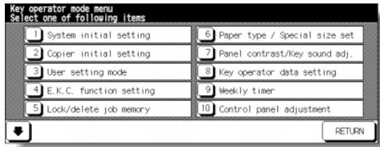
Control Panel Adjustment Screen
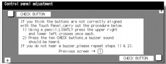
Procedure
1 Touch [10] Control panel adjustment on the Key Operator Mode Screen to display the Control Panel Adjustment Screen.
2 Touch the “+” indication at the upper right corner, then lower left corner on the screen. The present coordinates will be displayed in the message area of the screen.
NOTE:
When touching the "+" indications, it is recommended that you use a sharp point such as a pencil to be much more accurate.
3 Check that the X coordinate and Y coordinate displayed in the first line of the message area fall within the standard value displayed in the second line.
4 Touch the CHECK BUTTONs at the upper left and lower right corners on the screen to check if the buzzer tone functions normally.
5 If the coordinates fall out of the range of the standard value in step 3, or the buzzer tone does not sound in step 4, repeat the adjustment procedure from 2 to 4.
6 Press [1] to restore the Key Operator Mode Screen.
7 If no further changes are required, touch RETURN to restore the Basic Screen to perform copying operations.
[11] Tray Auto Select Setting
Select to be detected or not to be detected, and priority of detection for each tray when ATS/APS functions.
![KONICA MINOLTA 7255 - [11] Tray Auto Select Setting - 1](/content/2025/01/139764/images/c46ca78af4bb4586b8f0905281450c69214c81451fc340d5989a596c83ee1eb2.jpg)
Key Operator Mode Screen 1
![KONICA MINOLTA 7255 - [11] Tray Auto Select Setting - 2](/content/2025/01/139764/images/66a58c21388c697400f3d6fe488ca0533c1f34e8ddcaa444770da85330b77b9b.jpg)
Key Operator Mode Screen 2
![KONICA MINOLTA 7255 - [11] Tray Auto Select Setting - 3](/content/2025/01/139764/images/2039f869cb4679d9c9ba0e08e708f0058af9d163dba908ac1c57340c7d7c4dc2.jpg)
Tray Auto Select Setting Screen
Procedure
1 Touch [11] Tray auto select setting on the Key Operator Mode Screen to display the Tray Auto Select Setting Screen.
2 On the left half of the screen, touch to highlight each tray key, then select OFF or ON to specify whether the selected tray is to be automatically detected or not when ATS/APS functions.
3 Tray keys specified as ATS/APS ON will appear on the right half of the screen. Touch to highlight the desired tray key, then change its priority by using Up (▲) and Down (▼) arrow keys.
4 Touch OK to complete the setting and restore the Key Operator Mode Screen.
5 If no further changes are required, touch RETURN to restore the Basic Screen to perform copying operations.
Select the interval of time that must elapse before Auto Low Power and Auto Shut Off become activated. Auto Shut Off conserves more energy than Auto Low Power. The period of time selected for Auto Low Power cannot exceed the Auto Shut Off setting.
Key Operator Mode Screen

Power Save Setting Screen
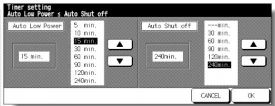
Procedure
1 Touch [12] Power save setting on the Key Operator Mode Screen to display the Power Save Setting Screen.
2 The periods of time currently selected for each power save function are located on the Timer Setting Screen below the Auto Low Power and Auto Shut Off indicators.
Touch the arrow keys (▲) and (▼) in each area to select a specific waiting period before activating the Auto Low Power or Auto Shut Off.
NOTES:
1 The period of time selected for Auto Low Power cannot exceed the Auto Shut Off setting.
2 If the same period of time as Auto Shut Off is selected for Auto Low Power, the Auto Shut Off will function instead of Auto Low Power.
3 Touch OK to complete the setting and restore the Key Operator Mode screen.
4 If no further changes are required, touch RETURN to restore the Basic Screen to perform copying operations.
This function allows you to change the Memory Settings listed below. See pp. 13-41 ~ 13-46 for details on Memory Settings.
SW No. Item
No. 01: Auto reset timer
No. 02: AUTO RESET key function
No. 03: RADF-Original effect
No. 04: Job memory auto recall (30)
No. 05: Finisher mode by Full-auto
No. 06: Initial by Key counter insert
No. 07: Erasure outside area of origin.
No. 08: RADF frame erasure selection
No. 09: Automatic tray switching
No. 10: Platen APS
No. 11: RADF APS
No. 12: Platen AMS
No. 13: RADF AMS
No. 14: Select tray when APS cancel
No. 15: Platen original size detect
No. 16: RADF original size detect
No. 17: Platen orig. size detect (SMALL)
No. 18: Rotation
No. 19: Staple mode reset-function
No. 20: Job offset operating
No. 21: Continuation print
No. 22: Key click sound
No. 23: 1 SHOT indication time
No. 24: Power save screen
No. 25: START key latch function
Setting (default is underlined)
OFF / 30 sec. / 60 sec. / 90 sec. / 120 sec./ 150 sec. / 180 sec. / 210 sec. / 240 sec. / 270 sec. / 300 sec.
Full-Auto / Initial Setting
RADF+AUTO RESET key selected / RADF selected
OFF/ON
Face down (Sub tray) / Non-sort / Sort / Staple sort / Stitch&Fold / Fold / Face up (Sub tray)
OFF/ON
Erased for except Platen (1:1) / Area outside of origin. erased / Erased for APS/AMS only
None / 1mm frame / 2mm frame / 3mm frame / 4mm frame / 5mm frame
OFF/ON
OFF/ON
OFF/ON
OFF/ON
OFF/ON
APS preferential tray / Tray 1 / Tray 2 / Tray 3 / LCT / Bypass tray
Only A series / Full size / AB series / Inch series
Only A series / Full size / AB series / Inch series
A5R / B6R / 5.5"x8.5"R / B5 / A4 / 8.5"x11"/ A6R
ON-APS/AMS only / ON-APS/AMS/Reduce only / ON-Always
OFF/ON
OFF/ON
OFF/ON
OFF/ON
3 seconds / 5 seconds
Shut off mode / Low power mode
OFF/ON
No. 26: STOP key function
No. 27: Auto select of Booklet copy
No. 28: E.K.C. password
No. 29: Arrow key change
No. 30: Exit direction of 1 sheet
No. 31: An interruption suspended way
No. 32: E.K.C. password input timing
No. 33: Key click sound (No paper/JAM)
No. 34: Reserve copy function
No. 35: Scan stop by a pull out tray
No. 36: Change page no. pos. (booklet)
No. 37: Timer which prohibits Print
No. 38: Bookmark function
No. 39: Delete of overlay image
No. 40: Orig. direction/binding mode
No. 41: Image stored cont. (SRV)
No. 42: Image recalled cont. (SRV)
No. 43: Exit direction
No. 44: I/P SCAN Address manual input
No. 45: I/P SCAN E-Mail function mask
No. 46: I/P SCAN HDD function mask
No. 47: I/P SCAN FTP function mask
No. 48: State of Platen/RADF (Reset)
No. 49: Priority tray (blank overlap)
No. 50: Auto Select the binding mode
No. 51: IP SCAN E-Mail file form
No. 52: IP SCAN HDD file form
No. 53: IP SCAN FTP file form
No. 54: Printing side
JOB momentary stop / JOB cancel
Automatic selection / Non Automatic selection
under 8 digits / 8 digits
Decimal point off (1 STEP 1mm) / (1 STEP 0.1mm)
Face up / Face down
Division of a number of copies / During of a number of copies
Auto reset timer / Complete job
OFF / 3 seconds / 5 seconds / 10 seconds
Reserve copy by folder select / Reserve copy by original set
ON/OFF
OFF/ON (Outside page numbering)
OFF / 15 seconds / 30 seconds / 60 seconds / 90 seconds
ON (It is cancel every JOB) / ON (It is not cancel every JOB) / OFF
Permission (Delete/Overwrite) / Prohibition (Delete/Overwrite)
Cancel every JOB / Not cancel every JOB
OFF / ON
OFF/ON
Face down / Face up
Permission/Prohibition
No mask/ Mask
No mask/ Mask
No mask/ Mask
Not keep/ Keep
Printer tray/ PI tray
OFF/ON
PDF/ PACKAGE TIFF
PDF/ PACKAGE TIFF/ DIVISION TIFF
PDF/ PACKAGE TIFF
OUTSIDE/INSIDE
Key Operator Mode Screen
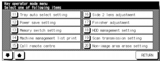
Memory Switch Setting Screen
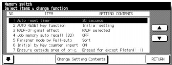
Procedure
1 Touch [13] Memory switch setting on the Key Operator Mode Screen to display the Memory Switch Setting Screen.
2 Use the procedure below to select the desired item and change the setting.
(1) Touch the arrow keys and at the right on the Memory Switch Setting Screen to select the desired item.
(2) Touch the arrow keys and at the lower left to scroll the screen.
(3) Touch Change Setting Contents to change the setting of the highlighted item.
(4) Repeat above steps (1) to (3) to make several changes in succession.
3 Touch RETURN to restore the Key Operator Mode Screen.
4 If no further changes are required, touch RETURN to restore the Basic Screen to perform copying operations.
The following functions can be provided by the Memory switch settings.
[1] Auto reset timer
Set the reset interval starting from the completion of a copying job until the machine returns to the initial condition.
[2] AUTO RESET key function
Set the condition of the following modes when [AUTO RESET] is pressed; Copy mode, Copy density, Magnification, Tray selection.
[3] RADF-Original effect
Set the machine condition when original is set on RADF in non-RADF mode with RADF unit closed.
[4] Job memory auto recall (30)
Job memory No. 30 is automatically recalled when power is turned on or when Auto Reset is restored.
This job recall function works only when Job No. 30 is registered.
[5] Finisher mode by AUTO RESET
Set the Finisher mode to be recalled when [AUTO RESET] is pressed.
[6] Initial by Key counter insert
Set the machine to return to the initial state when Key counter is inserted.
[7] Erasure outside area of original
Set the machine to delete the outside area of original.
[8] RADF frame erasure selection
Set Frame erasure to function anytime in RADF mode.
[9] Automatic tray switching
When paper is depleted during a copying job, the copier continues copying by switching to another tray that contains the same size paper.
[10] Platen APS
The copier automatically selects the same size copy paper as the original placed on the platen glass. (In reduction or enlargement mode, an appropriate paper size is selected according to the ratio selected.)
[11] RADF APS
The copier automatically selects the same size copy paper as the original placed on the RADF. (In reduction/enlargement mode, an appropriate paper size is selected according to the ratio.)
[12] Platen AMS
The copier detects the size of the platen original and selects the appropriate magnification ratio to correspond to the selected paper size.
[13] RADF AMS
After detecting the original size placed on the RADF the copier automatically selects an appropriate ratio for the copy when copy size is selected manually.
[14] Select tray when APS cancel
Select the tray to be automatically selected when APS is released.
[15] Platen original size detect
Select the series of the original paper size detected from the platen glass.
[16] RADF original size detect
Select the series of the original paper size detected from the RADF.
[17] Platen orig. size detect (SMALL)
Select the minimum original paper size detected from the platen glass.
[18] Rotation
Select to activate, activate the Rotation only when the APS/AMS functions, or activate the Rotation only when the APS/AMS/reduce functions.
[19] Staple mode reset-function
Staple mode is automatically canceled after a job is completed with Staple sort mode ON. (Sort mode is selected.)
[20] Job offset operating
Set the copier to offset the copies of different jobs.
[21] Continuation print
Set the copier to output multiple reserve jobs in succession.
[22] Key click sound
Activate or deactivate the sound each time a key is pressed on the touch panel .
[23] 1 SHOT indication time
Select the SHOT indication time function.
[24] Power save screen
Select the screen to display when pressing the [POWER Saver ON/OFF] key.
[25] START key latch function
Activate or deactivate the latch function.
[26] STOP key function
Select to display or not to display the confirmation message when [STOP] key is pressed.
[27] Auto select of Booklet copy
Set the copier with FS-210 mounted to automatically select the Booklet mode when Stitch&Fold or Fold output mode is selected.
[28] E.K.C. password
Select the acceptable number of digits for the EKC master key code.
[29] Arrow key change (Image Shift)
Select the 1 step unit of the touch key to specify the shift amount in Image shift.
[30] Exit direction of 1 sheet
Select to exit face up or face down when making only 1 sheet of copy.
[31] An interruption suspended way
Select the timing to stop the job in progress when [INTERRUPT] is pressed.
[32] E.K.C. password input timing
Set the input timing for the EKC password.
[33] Key click sound (No paper/JAM)
Select the duration of the buzzer for alerting that the machine has stopped being out of paper or due to paper misfeed.
[34] Reserve copy function
Set the selection for the reserve job setting.
[35] Scan stop by a pull out tray
Select to stop or continue the scanning job when a tray is pulled out.
[36] Change page no. pos. (booklet)
Set the machine to position the page numbers automatically on the outside edges of the copy when using Booklet with Page Numbering in Stamp.
[37] Timer which prohibits Printer
Set the timer to allow the printing job after operating the copying job.
[38]Bookmark function
Select to set theBookmark function only for the current job, set for all the following jobs, or deactivate the function.
[39] Delete of overlay image
In Overlay Memory setting, select to permit or prohibit deleting the selected image data previously stored in HDD, and also overwriting the data of the same name when storing new data in HDD.
[40] Orig. direction/binding mode
Select to reset or save the original direction and bind position settings made on the Special Original popup menu and Output Mode popup menu after completion of each copying job.
[41] Image stored cont. (SRV)
When storing the image data in HDD/PC in scanner/server mode, select to release or continue the scanner/server mode after completion of each image data storing job.
[42] Image recalled cont. (SRV)
When recalling the image data stored in HDD/PC in scanner/server mode, select to recall only one job or to continue recalling jobs.
[43] Exit direction
Select to exit face up or face down when making single-sided copies in non-sort or sort mode using finisher primary (main) tray.
[44] I/P SCAN Address manual input
Select to permit or prohibit entering the IP address manually to transmit the scanned image data.
[45] I/P SCAN E-Mail function mask
Select to mask or unmask the function to send the scanned image data by e-mail.
[46] I/P SCAN HDD function mask
Select to mask or unmask the function to store the scanned image data in the HDD.
[47] I/P SCAN FTP function mask
Select to mask or unmask the function to store the scanned image data in the FTP server.
[48] State of Platen/RADF (Reset)
When Auto Reset functions, select to reset the Platen/RADF mode to the initial setting, or save the previous setting.
[49] Priority tray (blank overlap)
When setting Cover with Blank sheet mode in Booklet and both printer tray and upper/lower tray of the cover sheet feeder are selected, select the tray to have priority in feeding the blank cover sheet.
[50] Auto Select the binding mode
Set the machine to conform the binding direction of the originals and printed sets each other.
[51] IP SCAN E-Mail file form
Select the file form when transmitting the scanned image data.
[52] IP SCAN HDD file form
Select the file form when storing the scanned image data in the HDD.
[53] IP SCAN FTP file form
Select the file form when storing the scanned image data in the FTP server.
[54] Printing side
Select the printed side when using Three-Folding mode.
Use this function to print out the list selected from the following items.
- Job memory list: Programmed contents of Job memory
- User management list: Home position settings selected by user
E.K.C. management list: Machine informations managed by EKC - Font pattern list: Font patterns used in the machine
Key Operator Mode Screen
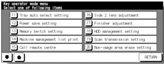
Management List Print Menu Screen
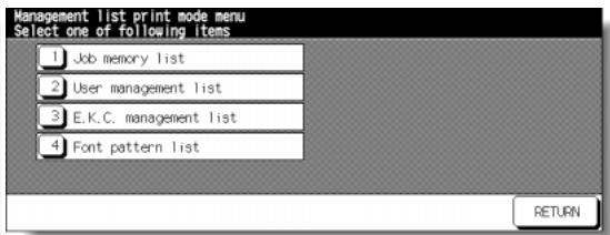
Procedure
1 Touch [14] Machine management list print on the Key Operator Mode Screen to display the Management List Print Menu Screen.
2 Touch the desired item on the screen. The Basic Screen will resume automatically.
3 Press [START] to start printing the selected list. To suspend printing, press [STOP]. Press [P] and [C] in order to return to the Management List Print Menu Screen.
4 Touch RETURN to restore the Key Operator Mode Screen.
5 If no further changes are required, touch RETURN to restore the Basic Screen to perform copying operations.
[15] Call Remote Centre
When activated, the Remote Diagnostics option is automatically monitored by a Konica service representative. In case of machine trouble, select the Call Remote Centre option. Your service representative will contact you to determine the appropriate means for resolving the problem.
□ Setting options: Call for JAM concerns; Call for SC concerns; Toner bottle supply call; Paper supply call; Call for image quality; Call for others
Key Operator Mode Screen
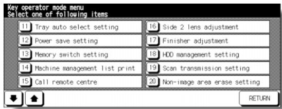
Call Remote Service Centre Screen
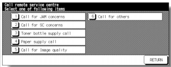
Start Call Screen
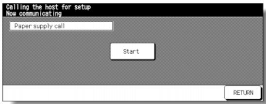
Procedure
1 Touch [15] Call remote centre on the Key Operator Mode Screen to display the Call Remote Service Centre Screen.
2 Touch [1] Call for JAM concerns; [2] Call for SC concerns; [3] Toner bottle supply call; [4] Paper supply call; [5] Call for Image quality; or [6] Call for others.
The Start Call Screen will be displayed.
3 Touch Start to call.
4 Touch RETURN to restore the Key Operator Mode Screen.
5 If no further changes are required, touch RETURN to restore the Basic Screen to perform copying operations.
[16] Side 2 Lens Adjustment
Use this function to set the adjustment data of the magnification ratio for each tray as Side 2.
Key Operator Mode Screen
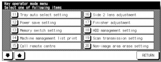
Side 2 Lens Adjustment Screen
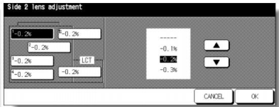
Procedure
1 Touch [16] Side 2 lens adjustment on the Key Operator Mode Screen to display the Side 2 Lens Adjustment Screen.
2 Touch to highlight the desired tray key, then touch arrow keys to select an adjustment data.
The selected data will be displayed on the highlighted tray key.
3 Touch OK to complete the setting and return to the Key Operator Mode Screen.
4 If no further changes are required, touch RETURN to restore the Basic Screen to perform copying operations.
Use this mode to make fine adjustments to each function of the finisher.
Key Operator Mode Screen

Finisher Adjustment Menu Screen
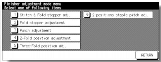
Stitch&Fold Stopper Position Adjustment Screen
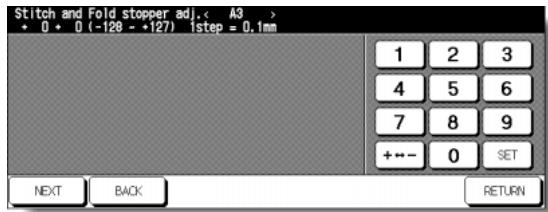
Fold Stopper Position Adjustment Screen
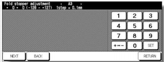
Punch Adjustment Menu Screen
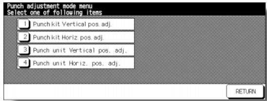
Punch Kit Vertical Position Adjustment Screen
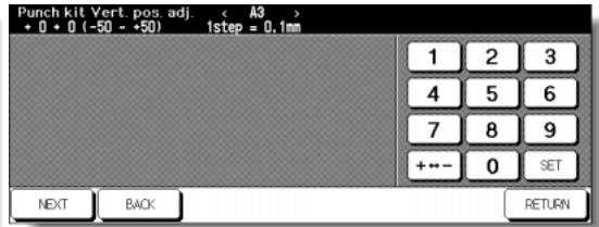
Punch Kit Horizontal Position Adjustment Screen
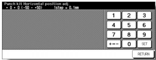
Punch Unit Vertical Position Adjustment Screen
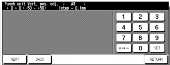
Punch Unit Horizontal Position Adjustment Screen
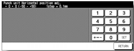
Z-Fold Position Adjustment Menu Screen
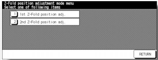
1st Z-Fold Position Adjustment Screen
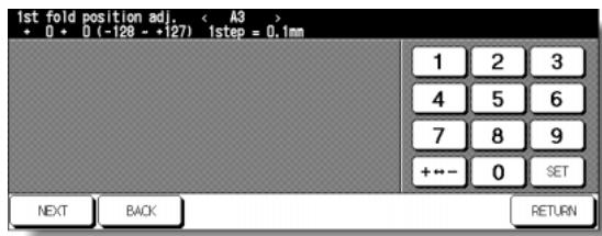
2nd Z-Fold Position Adjustment Screen
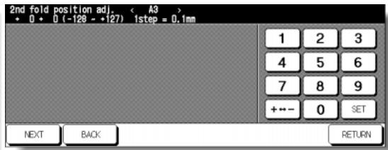
Three-Fold Position Adjustment Screen
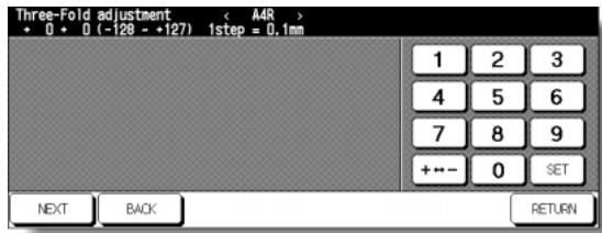
2 Positions Staple Pitch Adjustment Screen
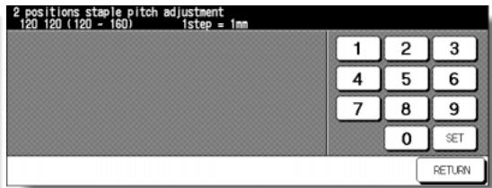
Procedure
1 Touch [17] Finisher adjustment on the Key Operator Mode Screen to display the Finisher Adjustment Menu Screen.
2 Touch the desired menu key to display the adjustment screen for each function.
3 Make fine adjustment on the screen.
To go on or back to another adjustment screen, touch NEXT or BACK.
Touching RETURN restores the Finisher Adjustment Menu Screen.
4 Touch RETURN to restore the Key Operator Mode Screen.
5 If no further changes are required, touch RETURN to restore the Basic Screen to perform copying operations.
Use this function to manage the image data stored in the optional HDD (HD-105) and to check the space available for new data.
- Password list/delete: Display the password list on the screen, or delete the image data (JOB) by deleting the corresponding password from the list.
- JOB auto delete period setting: Specify the period of time (1 to 52 weeks) to keep each data so that it will be deleted automatically when specified period has passed.
- State of HDD capacity: Check the space in percentage.
Key Operator Mode Screen
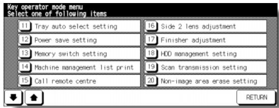
HDD Management Password Entry Screen
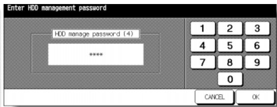
HDD Management Setting Menu Screen
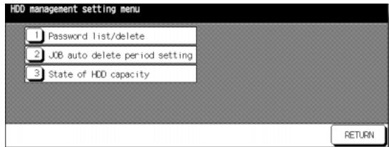
Password List/Delete Screen
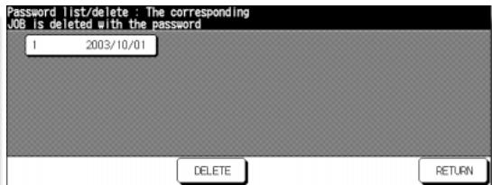
Password List/Delete Screen
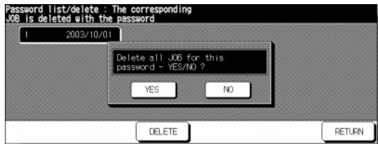
JOB Auto Delete Period Setting Screen
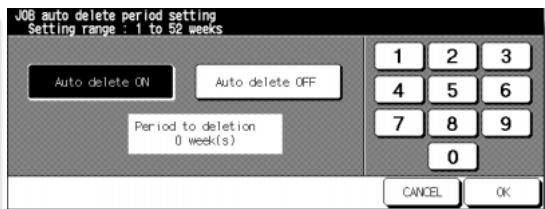
State of HDD Capacity Screen
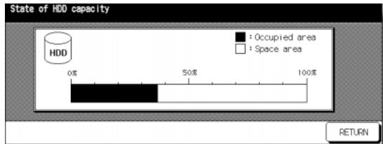
Procedure
1 Touch [18] HDD management setting on the Key Operator Mode Screen. The HDD Management Password Entry Screen will be displayed when the 4-digit HDD management password is set by service representative.
Otherwise, the HDD Management Setting Menu Screen displays without the password requirement.
If the HDD Management Password Entry Screen is displayed, use the keypad on the touch screen to enter your 4-digit HDD management password; then touch OK to display the HDD Management Setting Menu Screen.
NOTE:
The HDD management password is not initially set. Contact your service representative, if desired.
2 Touch the desired menu key to display the subsequent screen for each function.
To view the password list or delete the password and the corresponding image data:
(1) Touch [1] Password list/delete to display the Password List/Delete Screen.
(2) Touch to highlight the password key to be deleted, then touch DELETE. The popup menu will appear for confirmation.
(3) Touch YES to delete the selected password and all the data corresponding to it; or touch NO to cancel.
(4) Touch RETURN to return to the HDD Management Setting Menu Screen.
To delete the password and data automatically:
(1) Touch [2] JOB auto delete period setting to display the Job Auto Delete Period Setting Screen.
(2) Touch Auto delete ON to highlight it, then enter the number of weeks to keep each data, using the touch screen keypad. The maximum period of time is 52 weeks.
(3) Touch OK to complete the setting.
To check the current state of HDD capacity:
(1) Touch [3] State of HDD capacity to display the State of HDD Capacity Screen. The bar chart on the screen shows the current state of HDD capacity.
(2) Touch RETURN to return to the HDD Management Setting Menu Screen.
3 Touch RETURN to restore the Key Operator Mode Screen.
4 If no further changes are required, touch RETURN to restore the Basic Screen to perform copying operations.
Use this function to change or delete the address registered for transmitting the image data scanned on the machine.
The following three address types can be registered.
E-mail
HDD (box No.)
- FTP (FTP server address)
NOTE:
The [19] Scan Transmission Setting key will function only when IP-511 Type-A Printer Controller is installed on the machine.
Key Operator Mode Screen
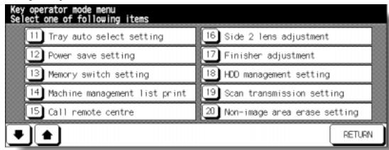
Scan Transmission Setting Screen (E-Mail)
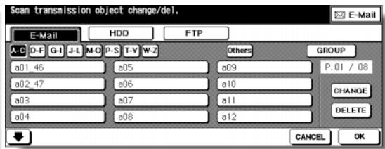
Change E-Mail Address Screen
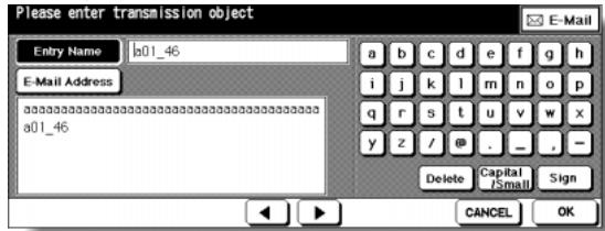
Scan Transmission Setting Screen (HDD)
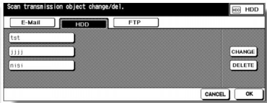
Change Box No. Screen

Scan Transmission Setting Screen (FTP)
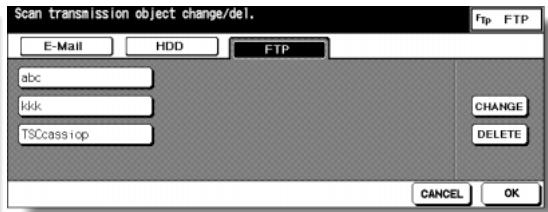
Change FTP Address Screen
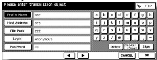
Procedure
1 Touch [19] Scan transmission setting on the Key Operator Mode Screen to display the Scan Transmission Setting Screen.
2 Select the desired address type.
Touch E-Mail, HDD, or FTP to display the registered name keys on each page.
NOTE:
Scan Transmission Setting Screen (E-Mail) is provided with the GROUP key. Touch the key to change the group name, if desired.
3 Select the name key to be changed or deleted.
Touch the Lower arrow key to scroll, or Upper arrow key to return.
To delete the address:
Touch to highlight the desired name key, then touch DELETE.
The selected key will be deleted from the screen.
To change the address:
(1) Touch to highlight the desired name key, then touch CHANGE.
The subsequent screen according to the address type will be displayed. (See previous page.)
(2) Touch to highlight the registered item key on the left, then change the information under that key using the alphabet keys on the screen.
(3) Touch OK on each screen to complete the setting and restore the Scan Transmission Setting Screen.
4 Touch OK to restore the Key Operator Mode Screen.
5 If no further changes are required, touch RETURN to restore the Basic Screen to perform copying operations.
Select the mode of Non-Image Area Erase function to be in effect when this feature is selected on the Application Selection Screen after power is turned on or after Auto Reset occurs.
Key Operator Mode Screen

Non-Image Area Erase Setting Screen
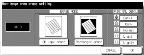
Procedure
1 Touch [20] Non-image area erase setting on the Key Operator Mode Screen to display the Non-Image Area Erase Setting Screen.
2 Select the desired erase mode and original density level.
Touch AUTO to let the machine select the erase mode and density level automatically.
To specify the erase mode manually, touch Oblique erase or Rectangle erase, as desired, then select the density level required. Five exposure levels are provided.
NOTE:
Select AUTO mode if the specified Oblique or Rectangle Erase mode does not function properly due to the type of set original.
3 Touch OK to complete the setting and restore the Key Operator Mode Screen.
4 If no further changes are required, touch RETURN to restore the Basic Screen to perform copying operations.
[21] Background Adjustment
Use this function to specify the density level against the background in each of four enhance modes (AUTO, Increase Contrast, Photo, Text).
NORMAL (standard) is initially selected.
![KONICA MINOLTA 7255 - [21] Background Adjustment - 1](/content/2025/01/139764/images/74eac93fb9672bf0f828b980550f07158a6e22ccb9407bd89f9b1d1458ca407b.jpg)
Key Operator Mode Screen
![KONICA MINOLTA 7255 - [21] Background Adjustment - 2](/content/2025/01/139764/images/95681b81279f86d8eca51c45899e3a98af2ba1a1d581e86d904c2f2e06282d42.jpg)
Background Adjustment Screen
Procedure
1 Touch [21] Background Adjustment on the Key Operator Mode Screen to display the Background Adjustment Screen.
2 Select the desired density level for each enhance mode.
Touch an enhance mode key to display the popup menu, then touch the desired level key to highlight it.
Nine density levels are provided for each mode except Increase Contrast which is provided with five levels from NORMAL to +4.
3 Touch OK to complete the setting and restore the Key Operator Mode Screen.
4 If no further changes are required, touch RETURN to restore the Basic Screen to perform copying operations.
Use this mode to make fine adjustments of the timing for printing or scanning function.
- Printer restart timing adj.: adjusts the lead edge timing.
- Printer regist loop adj.: adjusts the paper loop amount in the registration roller section.
- Printer pre-register adj.: adjusts the paper loop amount in each tray and ADU pre-registration roller section.
- Printer lead edge timing adj.: conducts a leading edge erasure amount adjustment.
- Scanner (Platen) restart timing adj.: adjusts lead edge timing for original scanning.
- RADF restart timing adj.: adjusts lead edge timing of RADF.
- RADF regist loop adj.: adjusts the original loop amount in the RADF registration roller section.
Key Operator Mode Screen
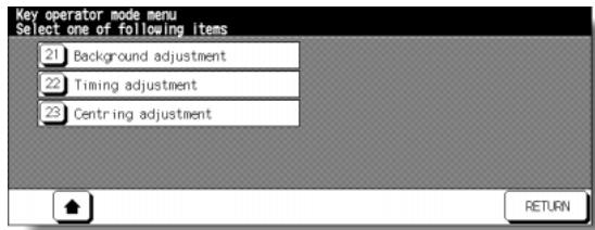
Timing Adjustment Menu Screen
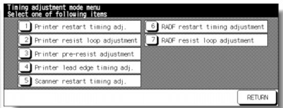
Printer Restart Timing Adjustment Screen
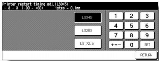
Printer Registration Loop Adjustment Screen
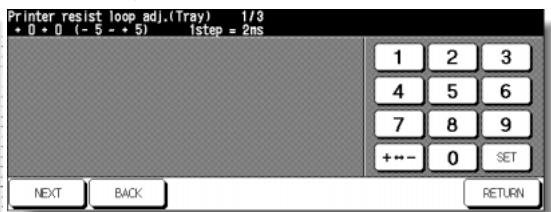
Printer Pre-registration Adjustment Screen
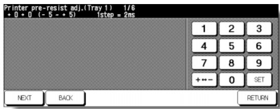
Printer Erasure Amount Adjustment Screen
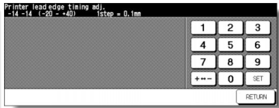
Scanner (Platen) Restart Timing Adjustment Screen
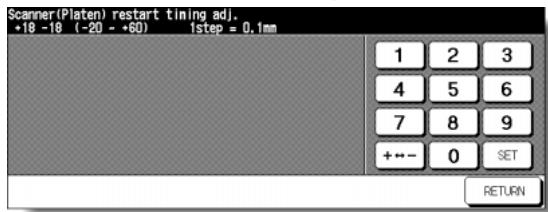
RADF Restart Timing Adjustment Screen
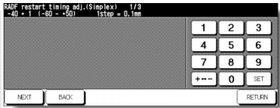
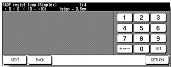
RADF Registration Loop Adjustment Screen
Procedure
1 Touch [22] Timing adjustment on the Key Operator Mode Screen to display the Timing Adjustment Menu Screen.
2 Touch the desired menu key to display the adjustment screen for each function.
3 Make fine adjustment on the screen. To go on or back to another adjustment screen, touch NEXT or BACK. Touching RETURN restores the Timing Adjustment Menu Screen.
4 Touch RETURN to restore the Key Operator Mode Screen.
5 If no further changes are required, touch RETURN to restore the Basic Screen to perform copying operations.
Use this mode to make various adjustments concerning the image centring function.
- Printer centring adjustment: adjusts the mis-centring of images vertical to paper feed direction.
- Scanner centring adjustment: adjusts the centring when scanning the platen original.
- RADF centring adjustment: adjusts the centring when scanning the RADF original.
Key Operator Mode Screen
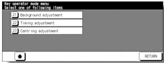
Centring Adjustment Menu Screen
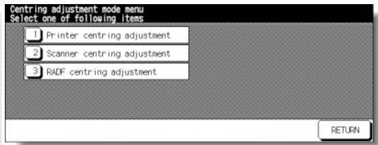
Printer Centring Adjustment Screen
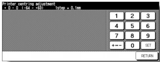
Scanner (Platen) Centring Adjustment Screen
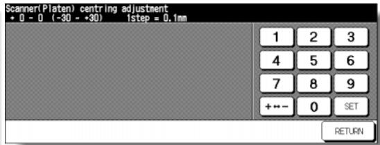
RADF Centring Adjustment Screen
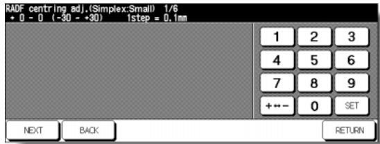
Procedure
1 Touch [23] Centring adjustment on the Key Operator Mode Screen to display the Centring Adjustment Menu Screen.
2 Touch the desired menu key to display the adjustment screen for each function.
3 Make fine adjustment on the screen.
To go on or back to another adjustment screen, touch NEXT or BACK.
Touching RETURN restores the Centring Adjustment Menu Screen.
4 Touch RETURN to restore the Key Operator Mode Screen.
5 If no further changes are required, touch RETURN to restore the Basic Screen to perform copying operations.
Index
Number
1 SHOT indication time 13-39
1.00 Magnification mode 3-14
1-2 Copying 3-21
1-2,2-2 3-21
2 in 1, 4 in 1, or 8 in 1 copying 9-10
2 Repeat, 4 Repeat, or 8 Repeat 9-36
2-1 3-27
2-1 Copying 3-27
2-2 Copying 3-21
A
ADD PAPER key 5-10
ADD TONER icon 12-2
Adding Toner 12-2
AE key 3-18
AMS (Automatic Magnification Selection) 3-12
An interruption suspended way 13-40
APPLICATION key 9-2
Application Selection Screen 9-2
APS (Automatic Paper selection) 3-10
Arrow key change (Image Shift) 13-40
AUTO Layout 9-42
Auto Low Power 2-21
AUTO RESET key function 13-39
Auto reset timer 13-39
Auto select of Booklet copy 13-40
Auto Select the binding mode 13-40
Auto Shut-Off 2-21
Automatic Exposure (AE) 3-18
Automatic tray switching 13-39
B
Background Adjustment 13-57
Basic Screen 2-16
Binding Margin 9-49
Binding Mode 3-53
BOOK MARK key 9-2
Booklet 9-13
Booklet mode outlet 2-8
Booklet tray 2-8
Bookmark function 13-40
C
C (CLEAR QTY.) key 3-6
Call for Service Screen 5-2
"Call for Service" message" 5-2
Call Remote Centre 13-48
Cartridge housing 2-9
CAUTION 1-6
Caution Indicator 1-3
Caution label 1-2
Centring Adjustment 13-60
Change page no. pos. (booklet) 13-40
Changing Paper Size 2-34
Chapter 9-7
CHECK key 3-55
Check Mode 3-55
Checking Copy Count 12-18
Cleaning image scanning section 12-16
Combination 9-10
Continuation print 13-39
Control Panel 2-15
Control Panel Adjustment 13-36
Conveyance/Fixing unit 2-5
Copier Initial Setting 13-10
Copy Limit 13-17
Copy Materials 12-20
Counter List Screen 12-18
Cover Sheet Feeding 7-20
D
DANGER 1-6
Date & Time Setting 13-4
Delete data from HDD/PC 10-13
Delete overlay image 13-40
Density Level 3-18
Density Shift 3-20
Diff. time setting 13-5
DIMM 10-2
Double-sided copy 3-21
Double-sided original 3-27
Drum unit 2-5
Dual Page 9-22
E
E.K.C. (Electronic Key Counter) 13-15
E.K.C. All Count Reset 13-20
E.K.C. Data Edit 13-17
E.K.C. Function 10-37
E.K.C. Function Setting 13-21
E.K.C. management list 13-47
E.K.C. password (Memory Switch) 13-40
E.K.C. password input timing 13-40
EKC master key code 13-15
EKC password 2-23, 13-15, 13-17
E-Mail Transmission Function 10-35
E-Mail Transmission Setting 13-8
Empty waste basket 12-12, 12-14
Environment 1-8
Environment Setup 10-35, 10-37, 10-47, 10-53
Erasure outside area of original 13-39
Exit direction 13-40
Exit direction of 1 sheet 13-40
Extension Lead 1-8
F
Finisher Adjustment 13-50
Finisher door 2-8
Finisher mode by AUTO RESET 13-41
Fixed magnification mode (RE) 3-15
Fixing unit 2-5
Fold mode 7-9
Font pattern list 13-47
Frame/Fold Erasure 9-39
FREE JOB key 3-35
Front door 2-3
FS-110/FS-210 Finisher 2-8
FTP server address 13-54
Full-Image Area 9-44
G
Gateway address 13-7
Guide width for mixed originals 11-9
H
HDD Job Information 10-31
HDD Management Setting 13-52
HDD STORE key 10-16
HELP key 4-6
Help Menu Screen 4-7
Help Mode 4-6
1
I/P SCAN Address manual input 13-40
I/P SCAN E-Mail function mask 13-40
I/P SCAN FTP function mask 13-40
I/P SCAN HDD function mask 13-40
Image data password 10-5
Image Edit mode 10-3
Image Insert 9-19
Image Recall mode 10-3
Image recalled cont. (SRV) 13-40
Image scanning section 12-16
Image Shift 9-46
Image Store & Output mode 10-3
Image Store/Delete mode 10-2
Image stored cont. (SRV) 13-40
Increase Contrast Mode (Enhance) 8-6
Initial by Key counter insert 13-39
Initial Setting 13-10
Inserting a new staple cartridge 12-8
Inserting new staple cartridge 12-5
Installation Space 1-9
Interleaf sheet 9-17
INTERRUPT key 3-59
Interrupt Mode 3-59
IP Address Setting 13-7
IP SCAN E-Mail file form 13-40
IP SCAN FTP file form 13-40
IP SCAN HDD file form 13-40
J
JAM JOB key 5-8
Job memory auto recall (30) 13-39
JOB MEMORY key 4-2
Job memory list 13-47
Job offset operating 13-39
Job Recall 4-5
Job Status (Web Utilities) 10-29
Job Status Screen 3-38
Job Store 4-2
K
Key click sound 13-39
Key click sound (No paper/JAM) 13-40
Key counter 2-3
Key Operator Data Setting 13-26
Key Operator Mode 13-2
KEY OPERATOR MODE key 13-2
Key Operator Mode Screen 13-2
Key Operator password 13-2
L
Language Select Setting 13-6
LCD touch screen 2-3, 2-15
Left partition glass 12-16
Lens Mode 3-14
Limited use of the copier 5-3
Line speed setting 13-7
Loading Paper 2-24
Loading Tabbed Sheets 2-31
Lock Job icon 13-22
Lock/Delete Job Memory 13-22
Low Power Mode 2-22
LT-402/412 Large Capacity Tray 2-7
Lunch Hour Off Setting 13-34
M
Machine Management List Print 13-47
Machine setting file 10-53
Main power switch 2-3
Maintenance Kit 12-20
Manual punch 7-24
Manual staple 7-24
Manual stitch & fold mode 7-25
Manual three-fold mode 7-24
"Memory Full" message 5-11
Memory Overflow 5-11
Memory Switch Setting 13-39
Mishandled paper 5-6
Mixed Original 8-8
MODE key 10-4
Multi-sheet bypass tray 3-29
N
Non-Image Area Erase 9-29
Non-Image Area Erase Setting 13-56
Non-standard size original 8-12
NORMAL key 3-18
0
OHP Interleave 9-17
Orig. direction/binding mode 13-40
Original binding direction 8-4
Original direction 8-2
Original Form 8-12
Original Information 11-8
Output Mode with Finisher 3-44
Output Mode with Shift Tray 3-50
Output Mode without Finisher 3-41
Overlay 9-61
Overlay Memory 9-64
P
P (COUNTER) key 5-4, 12-18
P (counter) key 2-15
Page space function 9-46
Panel Contrast / Key Sound Adjustment 13-25
Paper indicator 2-24
Paper Information 11-2
Paper jam position display 5-6
Paper size 3-10
Paper size for trays and equipments 11-5
Paper Type / Special Size Set 13-23
PAPER TYPE/SIZE key 3-29
Paper Weight 11-2
Periodic Check 1-13
Photo mode (Enhance) 8-6
PI-110 Cover Sheet Feeder 2-12
PK-110/120 Punching Kit 2-9
Platen AMS 13-39
Platen APS 13-39
Platen glass originals 11-8
Platen orig. size detect (SMALL) 13-39
Platen store mode 3-33
Plug Socket 1-7
PM CALL icon 5-4
PM counter 5-4
Positioning Mixed Originals 3-3
Positioning Originals 3-2
Positioning Originals on Platen Glass 3-5
Positioning Z-Folded Originals 3-4
Power cord 1-7
Power Lead 1-7
Power OFF/ON Screen 5-13
Power Plug 1-7
Power save screen 13-39
Power Save Setting 13-38
POWERSAVERON/OFFkey2-15,7-2
Power Source 1-7
Power switch 2-3
Precautions 1-12
PRE-JOB RECALL key 3-54
Preventive Maintenance 5-4
Previous job setting 3-54
Primary (Main) tray 2-8
Printing side 13-40
Priority tray (blank overlap) 13-40
Program Job 9-26
Proof Copy 3-55
PROOF COPY key 3-57
Punch mode 7-12
PZ-108 Punching / Z-Folding Unit 2-13
R
RADF 2-3
RADFAMS13-39
RADF APS 13-39
RADF frame erasure selection 13-39
RADF originals 11-9
RADF platen guide cover 12-17
RADF store mode 3-33
RADF-Original effect 13-39
RE key 3-15
Reduce & Shift 9-49
Remote Diagnostics option 5-2
Repeat 9-33, 9-36
Report code No. 5-2
Reserve 3-35
Reserve copy function 13-40
Reverse Image 9-31
Right & Left Bind 3-53
Rotation 7-5, 13-39
ROTATION OFF key 7-5
Routine Handling 1-12
s
Scan stop by a pull out tray 13-40
Scan Transmission Function 10-47
Scan Transmission Setting 13-54
SCAN/SERVER LED 10-4
Secondary (sub) tray 2-8
Select tray when APS cancel 13-39
Server functions 10-2
Setting Print Quantity 3-6
Sheet/Cover Insertion 9-3
Side 2 Lens Adjustment 13-49
Single-sided copy 3-27
SPECIAL ORIGINAL key 8-2
Special Original popup menu 8-2
Special paper in Multi-sheet bypass tray 11-7
Stacker unit 2-9
Stamp 9-52, 9-58
Staple cartridge 12-5, 12-8
Staple mode reset-function 13-39
START key latch function 13-39
State of Platen/RADF (Reset) 13-40
STATUS key 3-38
Stitch & Fold mode 7-9
STOP key 3-9
STOP key function 13-40
Store image in HDD/PC 10-4
Store Mode 3-33
Subnetmask 13-7
Summer time 13-4
System Initial Setting 13-4
T
Tandem mode 7-27
Text mode (Enhance) 8-6
Text/Photo Enhance 8-6
Three-Fold mode 7-18
Timer Action On/Off Setting 13-32
TIMER indicator 7-2
Timer interrupt password 7-3
Timer Interrupt Password Setting 13-35
Timer Setting 13-30
Timer which prohibits Print 13-40
Timing Adjustment 13-58
To Store Copy Paper 11-7
Toner access door 2-3
Toner cartridge 2-5, 12-2
Toner cartridge holder lever 2-5
Top Bind 3-53
Total counter 2-5
Transmit data from HDD to PC 10-8
Transparent film 9-17
Tray/Exit Tray Capacity 11-3
Tray1,2,3 2-3
Tray Auto Select Setting 13-37
Troubleshooting Tips 5-14
U
Universal tray 2-3
Unsuitable RADF originals 11-8
User Density Level 1 Setting 13-12
User Density Level 2 Setting 13-13
User Lens Mode Ratio Setting 13-14
User management list 13-47
User Setting Mode 13-12
USER1,USER2 (Density) 3-18, 13-12, 13-13
USERSET (Lens Mode) 13-12
V
Vertical/Horizontal Zoom Mode 7-6
W
Wake-up Screen 2-18
Warm-up Screen 2-18, 3-7
WARNING 1-6
Waste basket 2-9, 12-12, 12-14
Watermark 9-58
Web Utilities 10-26
Weekly Timer 7-2, 13-27
Weekly Timer master key code 13-27
Weekly Timer On/Off Setting 13-29
Work table 2-3
Z
Z-Fold Mode 7-16
Z-Folded Original 8-10
Zoom Mode 3-16
Recycled paper is used for the inside pages of this manual.
MANUFACTURER
KONICA MINOLTA BUSINESS TECHNOLOGIES, INC.
TOKYO JAPAN
- Konica 7255 7272
- #
- ENERGY STAR® Program
- Auto Low Power
- Automatic Shut-Off
- Automatic Duplex Copying
- Basic
- Section 1: Safety Information
- Section 2: Machine Information
- Section 3: Copying Operations
- Section 4: Job Memory & Help Mode
- Section 5: Troubleshooting
- Section 6: Machine Specifications
- Advanced
- Section 7: Advanced Information
- Section 8: Special Original
- Section 9: Applications
- Section 9: Applications (continued)
- Section 10: Network Function
- Section 11: Paper and Original Information
- Section 12: Maintenance & Supplies
- Section 13: Key Operator Mode
- Section 13: Key Operator Modes (continued)
- Index
- - AE - Automatic Exposure
- - AMS - Automatic Magnification Selection
- - APS - Automatic Paper Selection
- - ATS - Automatic Tray Switching
- - Auto Layout
- - Auto Low Power
- - Auto Reset
- - Auto Shut-Off
- - Booklet
- Chapter
- Combination
- - Copy Density
- - Copy Mode
- Counter List
- Density Shift
- - Dual Page
- - Frame/Fold Erasure
- - Full-Image Area
- - Image Insert
- - Image Shift
- - Interrupt Copying
- Job Memory
- Job Status
- - Lens Mode (RE, Zoom)
- Machine Status Confirmation
- - Manual Shut-off
- - Mixed Original
- Network Function (option)
- - Non-Image Area Erase
- - Non STD Size for Multi-Sheet Bypass Tray
- Non STD Size for Original
- - OHP Interleave
- - Output Mode for FS-110/210 Finisher with PI-110 Cover Sheet Feeder Installed:
- Proof Copy
- - Punch Mode for FS-110/210 Finisher with PK-110/120/120 Type-A Punching Kit Installed:
- - Punch/Z-Fold Mode for FS-110/111/210 Finisher with PZ-108 Punching/Z-Folding Unit Installed:
- - Punch/Z-Fold Mode for FS-110/111/210 Finisher with PZ-109 Punching/Z-Folding Unit Installed:
- Repeat
- - Reserve
- - Reverse Image
- - Rotation
- - Rotation Exit (Rotation Sort / Rotation Group)
- - Server Function (option)
- - Sheet/Cover Insertion
- - Stamp
- Staple
- - STD Size (Special)
- - Tab Paper
- Tandem Mode for Two Copiers
- - Text/Photo Enhance
- - 用户 Set Density (USERSET 1, USERSET 2)
- Weekly Timer
- Wide Size Paper
- - Z-Folded Original
- SECTION
- Safety Information
- Precautions for Installation and Use
- CAUTION
- DANGER:
- WARNING:
- CAUTION:
- Please Be Reminded!
- Power Source
- CAUTION: Plug Socket
- CAUTION: Power Plug and Lead
- CAUTION: Connecting Multiple Loads to One Socket Outlet Prohibited
- CAUTION: Extension Lead
- Environment
- CAUTION: Prevention of Fire
- CAUTION: Prevention of Short Circuit
- CAUTION: Temperature and Humidity
- CAUTION: Ventilation
- CAUTION: Vibration
- CAUTION: Transportation
- CAUTION: Installation Space
- Precautions for Routine Handling
- WARNING: High Voltage
- CAUTION: Actions in Response to Troubles
- CAUTION: Prohibition of Machine Modification
- CAUTION: Prevention of Machine Troubles
- CAUTION: Recommendation of Periodic Check
- CAUTION: Toner
- CAUTION: Paper
- CAUTION: Power Saver and Weekly Timer
- CAUTION: Inside the Booklet Mode Outlet
- CAUTION: Finisher Paper Exit Outlet
- CAUTION: Fixing Unit
- WARNING: Drum Unit
- CAUTION: Dispose of a Disused Copying Machine
- CAUTION: Paper Capacity for the Exit Tray
- CAUTION: Finisher Paper Capacity
- CAUTION: Finisher Primary (Main) Tray
- CAUTION: SHIFT TRAY AND PAPER EXIT OUTLET
- 2
- Machine Information
- Machine Configuration, Turning On the Power and Loading Paper
- External Machine Items
- HINT
- Internal Machine Items
- Standard/Optional Equipment
- LT-402/LT-412 Large Capacity Tray
- FS-110/FS-210 Finisher (+PK-110/120/120 Type-A Punching Kit)
- FS-111 Finisher
- PI-110 Cover Sheet Feeder
- PZ-108/PZ-109 Punching / Z-Folding Unit
- SF-101 Shift Tray
- Control Panel Layout
- Basic Screen
- Folder keys
- Notice icons
- Turning On the Main Power Switch and Power Switch
- To Turn On the Power
- Turn ON the main power switch.
- Turn ON the sub power switch.
- The Wake-up Screen and Warm-up Screens will be displayed.
- The Basic Screen will be displayed.
- FOR DETAILS
- To Turn Off the Power
- Turn OFF the sub power switch.
- Turn OFF the main power switch.
- Reducing the Power in Standby Mode (Auto Low Power)
- Shutting Off Automatically (Auto Shut-Off)
- HINTS
- Shutting Off / Reducing the Power Manually
- Press [POWER Saver ON/OFF] for one second or longer, then release it.
- The Shut-Off mode will be activated.
- Entering an EKC Password (EKC)
- Enter EKC password.
- Press [START].
- Start a copying job.
- Press [C] while pressing [P] .
- Loading Paper in Tray 1 and 2
- Withdraw tray 1 or 2.
- Open the paper feed roller.
- Place paper on the tray with the curl side turning up.
- Push in the tray until it locks into place.
- Loading Paper in Tray 3 and 4
- Withdraw tray 3 or 4.
- While pressing the release knob, move the rear side guide plate against the paper.
- When paper is seated properly, close the paper feed roller.
- Push in the tray until it locks into place.
- Loading Paper in LCT (LT-402/LT-412)
- Repeat the steps 2 and 3 until the bottom plate will not go down any more.
- Close the LCT top door.
- Loading Paper in Multi-Sheet Bypass Tray
- Loading Tabbed Sheets in Tray 3 or 4
- Loading Tabbed Sheets in LCT (LT-402/LT-412)
- Loading Tabbed Sheets in Multi-Sheet Bypass Tray
- 3
- Copying Operations
- How to Make a Basic Copy
- Positioning Originals in RADF
- Positioning originals in Normal mode
- Arrange originals in order.
- Position original(s) FACE UP in the document feeder tray.
- Adjust paper guides.
- Positioning originals in Mixed original mode
- Position mixed originals FACE UP, aligned with the left rear side of the document feeder tray.
- Positioning originals in Z-Folded original mode
- Positioning Original on Platen Glass
- Raise the document feeder.
- To Set Print Quantity
- Enter the desired print quantity from the control panel keypad.
- To Change Print Quantity
- Press [C (CLEAR QTY.)].
- Enter the correct quantity.
- Turn on the main power and power switches of the machine.
- Touch the LCD panel to change the Warm-up Screen to the Basic Screen.
- Set the desired copying conditions, and enter the print quantity.
- Position original(s) FACE UP in the RADF or FACE DOWN on the platen glass.
- Press [START].
- If setting more than one reserve job, touch the next FREE JOB to highlight it.
- To Select Paper Size Automatically (APS)
- Touch to highlight APS at lower right corner of the Basic Screen.
- Select additional copy conditions, as desired.
- Enter the desired print quantity from the control panel keypad.
- Position original(s).
- To Specify Desired Paper Size (AMS)
- To Copy in 1.00 Magnification Mode
- Close the RADF securely, then press [AUTO RESET].
- To Copy in Fixed Magnification Mode (RE)
- Touch RE on the Basic Screen.
- Select the desired magnification.
- Select additional copy conditions, as desired.
- Enter the desired print quantity from the control panel keypad.
- Position original(s).
- Press [START].
- To Copy in Zoom Mode
- Touch ZOOM on the Basic Screen.
- Touch Vert./Horiz. on the popup menu, if not highlighted, then set the desired zoom ratio.
- Touch OK.
- Select additional copy conditions, as desired.
- Enter the desired print quantity from the control panel keypad.
- Position original(s).
- Press [START].
- To Select Copy Density
- Touch SPECIAL ORIGINAL on the Basic Screen.
- Select the desired mode.
- Press [P (COUNTER)].
- Press any key (from 0 to 5) using the keypad to determine the Density shift.
- Touch OK on the Special Original popup menu.
- Using RADF
- Touch 1-2 or 2-2 on the Basic Screen to highlight it.
- Check and specify the original set direction and binding mode.
- Select the binding mode.
- Position originals FACE UP in the document feeder according to the original direction specified in step 2.
- Using Platen Glass
- Check and specify the original set direction and binding mode.
- Select the binding mode.
- Position original FACE DOWN on the platen glass according to the original direction specified in step 1.
- Touch 1-2 on the Basic Screen to highlight it.
- Select additional copy conditions, as desired.
- Enter the desired print quantity from the control panel keypad.
- Press [START] to scan.
- Replace the original on the platen glass with the back side image original, then press [START].
- Touch STORE to exit the Store mode.
- Press [START] to print.
- Making Single-Sided Copy from Double-Sided Originals (2-1)
- Touch 2-1 on the Basic Screen to highlight it.
- Position originals FACE UP in the document feeder according to the original direction specified in step 2.
- Copying Using Special Paper (Multi-Sheet Bypass Tray)
- Open the Multi-sheet bypass tray, and load the copy paper.
- Touch the Bypass key to highlight it.
- Touch PAPER TYPE/SIZE
- Touch the desired paper type key.
- Specify the paper size.
- Touch OK to return to the Basic Screen.
- Select additional copy conditions, as desired.
- Enter the desired print quantity from the control panel keypad.
- Position original(s) FACE UP in the document feeder or FACE DOWN on the platen glass.
- Press [START].
- To Scan Originals into Memory (Store Mode)
- Make copying selections, as desired.
- Touch STORE on the Basic Screen to highlight it.
- Press [START] to scan.
- Touch STORE to exit the Store mode.
- To Set Next Copying Job (Reserve)
- Press [START] to start scanning/printing for the current job.
- Touch FREE JOB to highlight it.
- Select copy conditions for the reserve job, as desired.
- Position original(s) after completing the scan for the current job.
- Press [START] to start scanning for the reserve job.
- Copying of the reserve job will start automatically after completing the current job.
- To Check/Control Jobs in Progress (Job Status Screen)
- Touch STATUS on the Basic Screen.
- Perform the desired setting on the screen.
- Touch OK on the Job Status Screen.
- Contents of Job Status Screen
- TANDEM CONNECTED INFORMATION:
- When using Rotation sort or Rotation group mode, load the same paper size into two trays in different orientation.
- Select the desired output mode.
- FOR DETAILS: Output Icons on the Basic Screen
- Primay (Main) Tray:
- Secondary (Sub) Tray:
- >>>Specification for Output Modes with Finisher
- To set Non-sort or Sort mode:
- To set Staple-sort mode:
- To set Group mode or output to Secondary (sub) tray:
- >>>Specification for Output Modes with Shift Tray
- To set Group mode:
- Position original(s).
- Press [START].
- Press [JOB MEMORY] on the control panel.
- Touch PRE-JOB RECALL.
- Touch OK to return to the Basic Screen.
- Change the settings recalled on the screen, if desired.
- When all settings are acceptable, position original(s) in the document feeder or on the platen glass, then press [START].
- Checking Feature Selections and Proof Copying
- Select the desired copy conditions and enter the desired print quantity.
- Position original(s).
- Press [CHECK] on the control panel.
- To change the settings:
- To release the settings:
- Press [PROOF COPY] on the control panel or touch PROOF COPY on the Check Screen.
- Change the print quantity, as required.
- Press [INTERRUPT] on the control panel.
- Set copy conditions, as desired.
- Position original(s).
- Press [START] to start the interrupt copying.
- When Interrupt copying is completed, press [INTERRUPT] again.
- Press [START] to resume copying.
- Memory & Help Mode
- How to Use Helpful Functions
- Make job selections from the Basic Screen and/or Application Selection Screen.
- Press [JOB MEMORY] on the control panel.
- Touch STORE.
- Review the settings on the Job Store Check Screen.
- Touch OK.
- Touch to highlight one of the keys numbered from 1~30 to store the job under that number.
- Touch OK.
- Enter a job name.
- Touch OK.
- Touch OK to complete the setting and return to the Basic Screen.
- Touch to highlight a job number key to select a job you want to recall.
- If desired, touch JOB CHECK.
- Touch OK.
- Position original(s), then press [START] to print.
- Displaying Screen for Operation Guide (Help Mode)
- To Display Help Screen from Basic Screen
- Return to the Basic Screen, then press [HELP].
- Touch the desired key to display specific information.
- Touch EXIT to return to the Basic Screen.
- FOR DETAILS: Help Menu Screen
- To Display Help Screen from Other Screens
- While in any screen other than the Basic Screen, press [HELP].
- Touch EXIT.
- 5
- Troubleshooting
- How to Handle Machine Troubles
- When “Call for Service” Message Is Displayed
- Make note of the Report code No. indicated in the second line of the message area.
- Turn OFF the sub power switch and main power switch.
- Limited Use of the Copier in Trouble
- To Check the PM Counter
- Touch EXIT.
- Touch Graphic Illustration on the screen.
- Follow the procedure on the screen to remove misfed paper.
- When completed, the Basic Screen will be restored.
- WARNING
- When “JAM” Appears on Folder Key (Or Arrow Key Flashes)
- Display the Jam Position Screen.
- Touch Graphic Illustration.
- Follow the procedure on the screen to remove misfed paper.
- Press [START].
- Touch FREE JOB to continue the reserve job setting.
- When “ADD PAPER” Appears on Folder Key (Or Arrow Key Flashes)
- Display the Basic Screen for the print job in progress.
- Check the flashing tray key, then supply that empty tray with copy paper.
- Press [START].
- Touch FREE JOB to continue the reserve job setting.
- When “Memory Full” Message Is Displayed (Memory Overflow)
- Memory Overflow in Current Job
- Memory Overflow in Reserve Job
- When Power OFF/ON Screen Is Displayed
- COPIER DOES NOT OPERATE WHEN POWER SWITCH IS ON
- COPY IMAGE IS TOO LIGHT
- COPY IMAGE IS TOO DARK
- COPY IMAGE IS NOT CLEAN OR SHOWS SPOTS
- COPY PAPER MISHANGLES DURING COPYING
- COPY IMAGE CAN BE RUBBED OFF
- MAGNIFICATION CANNOT BE CHANGED
- DUPLEX MODES CANNOT BE SELECTED
- COPYING DOES NOT BEGIN AFTER PRESSING [START]
- COPYING DOES NOT RESUME AFTER MISHHANDLED PAPER IS REMOVED
- COPY QUALITY IS POOR
- THE ORIGINAL PAPER IS MISHHANDLED OR SKEWED IN THE DOCUMENT FEEDER
- COPY IMAGE IS SKEWED WHEN BYPASS IS USED
- USING EKC, COPIES CANNOT BE MADE AFTER PASSWORD IS ENTERED
- FINISHER DOES NOT OPERATE
- RADF INDICATOR WILL NOT LIGHT AFTER [AUTO RESET] IS PRESSED
- RADF LIGHT IS FLASHING
- ADD TONERMESSAGE IS DISPLAYED
- CALL FOR PM IS DISPLAYED INMESSAGE AREA
- APS SELECTS THE WRONG PAPER SIZE
- IN MIXED ORIGINAL MODE, AMESSAGE TO LOAD A REQUIRED PAPER SIZE DISPLAYS, EVEN THOUGH THAT SIZE IS LOADED IN ONE OF THE TRAYS
- THE BASIC SCREEN DOES NOT DISPLAY SETTINGS AS DESCRIBED IN INSTRUCTION MANUAL
- "PLEASE CHECK ORIGINAL"
- SHEET INSERTION RESULT IS NOT AS EXPECTED
- FINISHER STAPLE RESULT IS NOT AS EXPECTED
- COPIES SKEW IN THE STAPLED SETS
- USING PUNCH, COPIES CANNOT BE PUNCHED
- COPIES CANNOT BE STAPLED OR PUNCHED IN POSITION
- Machine Specifications
- Main Body & Option Specifications
- Main Body
- RADF (DF-322)
- FS-110/210 In-Bin Stapler Finisher
- FS-111 In-Bin Stapler Finisher
- PK-110/120 Punching Kit
- PK-120 Type-A Punching Kit
- PZ-108 Punching / Z-Folding Unit
- PZ-109 Punching / Z-Folding Unit
- LT-402 Large Capacity Tray
- LT-412 Large Capacity Tray
- Expanded Memory Unit
- Others
- Advanced Information
- How to Use Advanced Functions
- Press [POWER SAVER ON/OFF] on the control panel.
- Enter the password.
- Set the hour for the interrupt use.
- Set the minute for the interrupt use.
- When Timer Interrupt of the copier is finished, press [POWER SAVER ON/OFF] for one second or longer, then release it.
- Touch ROTATION OFF on the Basic Screen to highlight it.
- Touch to deselect ROTATION OFF to resume this function.
- Touch Vert. on the popup menu to highlight it, then set the vertical zoom ratio.
- Touch OUTPUT MENU on the Basic Screen
- Touch MAIN TRAY, if not highlighted.
- Touch STITCH & FOLD or FOLD, as desired.
- Touch OK on the Output Mode popup menu.
- Select additional copying features, as required.
- >>>Specifications for Punch Mode
- Touch PUNCH.
- Touch the desired punch position key on the screen to highlight it.
- Touch OK on the Punch Position popup menu to restore the Output Mode popup menu.
- Touch OK on the Output Mode popup menu to complete the setting and return to the Basic Screen.
- Specify the original set direction.
- Touch Z-FOLD to highlight it.
- Touch OK on the Output Mode popup menu to complete the setting and return to the Basic Screen.
- Position originals.
- Touch THREE-FOLD to highlight it.
- Touch OK on the Output Mode popup menu to complete the setting and return to the Basic Screen.
- Select additional copying features, as required.
- Enter the desired print quantity from the control panel keypad.
- Position originals.
- Press [START].
- >>>Specifications for Cover Sheet Feeding
- Touch COVER SHEET.
- Touch FRONT COVER and/or BACK COVER to highlight it, then select the covers tray.
- Specify the insertion location.
- Touch OK to restore the Output Mode popup menu.
- Touch OK on the Output Mode popup menu.
- Select additional copying features, as required.
- Load the cover sheet paper into the optional cover sheet feeder of the FS-110/210 Finisher.
- Enter the desired print quantity from the control panel keypad.
- Position originals.
- Press [START].
- FS-110 Finisher + PI-110 Cover Sheet Feeder
- FS-110 Finisher + PI-110 Cover Sheet Feeder + PK-110/120/120 Type-A Punching Kit
- FS-210 Finisher + PI-110 Cover Sheet Feeder
- FS-210 Finisher + PI-110 Cover Sheet Feeder + PK-110/120/120 Type-A Punching Kit
- Place a set of paper to be finished into the lower tray of the cover sheet feeder, as described below for each mode.
- Press Staple Mode Selection button and/or Punch button to select the desired mode.
- Press Start/Stop button.
- >>>Specifications for Tandem Mode
- Turn power on by pressing the Power switches of the two copiers.
- Touch OUTPUT MENU on the Basic Screen of either copier.
- Touch TANDEM to highlight it, then touch OK.
- Select the desired copying conditions on the primary copier.
- Enter print quantity on the primary copier, using the keypad.
- Position original(s) FACE UP in the document feeder or FACE DOWN on the platen glass of the primary copier.
- Press [START] on the control panel of the primary copier.
- FOR DETAILS: Entering reserve job during Tandem mode copying
- Interrupt mode during Tandem mode copying
- To Stop Scanning/Printing
- Press [STOP] on the control panel of the primary copier.
- Touch CONTINUE to go on, or EXIT to delete all the scanned data and to release the tandem mode.
- Press [STOP] on the control panel of the secondary copier.
- Touch CONTINUE to go on, or EXIT to delete all the data transmitted to the secondary copier and to release the tandem mode.
- Copying with the Allocation recovery mode:
- When a paper jam, SC-code (E-code, F-code) trouble or unloaded paper occurs on either the primary or secondary copier:
- When memory overflow occurs on either the primary or secondary copier:
- When the power is turned off on either the primary or secondary copier:
- Special Original
- Touch to highlight the desired original direction key.
- Touch OK to complete the setting and return to the Basic Screen.
- Touch to highlight the desired binding direction key.
- Touch OK to complete the setting and return to the Basic Screen. The SPECIAL ORIGINAL key on the Basic Screen is highlighted.
- Make other compatible selections.
- Position originals FACE UP in the document feeder or FACE DOWN on the platen glass.
- Making Copy Quality Closer to Originals (Text/ Photo Enhance)
- Text Mode
- Photo Mode
- Increase Contrast Mode
- Touch Text, Photo, or Increase Contrast, as required.
- Position original(s) FACE UP in the document feeder or FACE DOWN on the platen glass.
- >>>Specifications for Mixed Original
- Touch Mixed Original.
- Copying Z-Folded Originals (Z-Folded Original)
- Touch Z-Folded original.
- Position mixed original(s) FACE UP in the document feeder.
- >>>Specifications of Original Form
- Touch Non STD Size or Tab paper.
- Touch the desired size key.
- Touch OK on the popup menu to complete the setting.
- Touch OK to complete the setting and return to the Basic Screen.
- Load copy paper.
- Position original(s) FACE UP in the document feeder, or FACE DOWN on the platen glass.
- Applications
- How to Use Application Functions
- Touch APPLICATION on the Basic Screen.
- Touch OK on the Application Selection Screen.
- Inserting Sheets and Covers (Sheet/Cover Insertion)
- >>>Specifications for Sheet/Cover Insertion
- Touch CHANGE COVERS TRAY to select the cover sheet tray source.
- When selecting Insertion mode: Enter the page number.
- Touch CHANGE INSERTION TRAY to select the insertion tray source.
- When all settings are completed, touch OK to return to the Application Selection Screen.
- Enter the desired print quantity from the control panel keypad.
- Position originals FACE UP in the document feeder.
- Press [START].
- FOR DETAILS: Entering Page Numbers
- NOTES:
- Locating Title Pages on the Right Side (Chapter)
- Touch Chapter on the Application Selection Screen.
- Use the control panel keypad to enter the page number of each title page.
- OPTION
- When all entries are made, touch OK.
- Touch OK on the Application Selection Screen.
- Position originals FACE UP in the document feeder.
- Lay Out Several Pages onto One Sheet (Combination)
- Touch Combination on the Application Selection Screen.
- Select the desired Combination mode.
- Select the desired original direction.
- Position originals FACE UP in the document feeder.
- Making a Multiple Page Signature Booklet (Booklet)
- Load Copy Paper.
- Touch APPLICATION on the Basic Screen.
- Touch Booklet on the Application Selection Screen.
- Touch to highlight the desired Booklet mode key.
- Touch OK on the Application Selection Screen.
- Select the tray in which you loaded copy paper in step 1.
- Select the desired copy mode.
- FOR DETAILS: Selecting Fold / Stitch&Fold Mode
- NOTE:
- Copying onto Transparent Films (OHP Interleave)
- >>>Specifications for OHP Interleave
- Insert a sheet of transparent film into the Multi-sheet bypass tray.
- When interleaf sheet is needed, load copy paper in any other tray to match the size of transparent films.
- Touch APPLICATION on the Basic Screen.
- Touch OHP Interleave on the Application Selection Screen.
- Select the desired OHP Interleave mode, then touch OK.
- Position original(s) FACE UP in the document feeder or FACE DOWN on the platen glass.
- Inserting Images into Printed Sets (Image Insert)
- Touch Image Insert on the Application Selection Screen.
- Use the control panel keypad to enter the page number.
- When all page number entries are made, touch OK.
- Scan the document feeder images: Position originals FACE UP in the document feeder.
- Scan the platen glass images.
- Repeat steps 9 and 10 for all originals.
- Touch STORE to exit the Store mode.
- Press [START].
- Dividing an Image into Right and Left Pages (Dual Page)
- Touch Dual Page on the Application Selection Screen.
- Select the desired Dual Page mode.
- Touch CHANGE BINDING POSITION to select the output order according to the original pagination.
- Select the desired copy mode, magnification, and paper size.
- Position original(s).
- Press [START] to scan.
- Scanning Original for Cover
- Programming Different Settings for an Output Job (Program Job)
- >>>Specifications for Program Job
- Touch Program Job on the Application Selection Screen.
- Touch OK on the Application Selection Screen.
- Select the desired copy conditions.
- Position originals FACE UP in the document feeder or FACE DOWN on the platen glass.
- Touch CONFIRM.
- Repeat steps 4 to 7 until all JOB originals are scanned.
- Select the desired output mode and enter the print quantity from the control panel keypad.
- Touch STORE to exit the Store mode.
- Erasing Outside of the Original (Non-Image Area Erase)
- >>>Specifications for Non-Image Area Erase
- Touch Non-image Area Erase on the Application Selection Screen.
- Select magnification and paper size, as desired.
- Position original FACE DOWN on the platen glass.
- FOR DETAILS: Oblique Erase and Rectangle Erase Modes
- Having Any Problem?
- Reversing Colour in Black and White Image (Reverse Image)
- Touch Reverse Image on the Application Selection Screen.
- Position original(s) FACE UP in the document feeder or FACE DOWN on the platen glass.
- Repeating Selected Image Area (Repeat: Vert./ Horiz. Mode)
- >>>Vertical/Horizontal Width Setting Mode Specifications
- Touch Repeat on the Application Selection Screen.
- Touch Vertical/Horizontal, then specify the vertical and horizontal widths of the scanning area.
- Select the desired magnification and paper size.
- Position original FACE DOWN on the platen glass.
- Repeating Automatically Or Selecting Repeating Times(Repeat: AUTO/ Repeat Mode)
- >>Auto Detection/ Repeat Mode Specifications
- Touch to highlight the desired mode key.
- Position original.
- Eliminating Black Copy Marks Along Borders (Frame/Fold Erasure)
- Touch Frame/Fold Erasure on the Application Selection Screen.
- Specify the erasure amount in the selected mode.
- Position original(s) FACE UP in the document feeder or FACE DOWN on the platen glass.
- Copying Image in the Centre of Copy Paper (AUTO Layout)
- Touch AUTO Layout on the Application Selection Screen.
- Select the desired magnification and paper size on the Basic Screen.
- Touch Full-image Area on the Application Selection Screen.
- Touch Image Shift on the Application Selection Screen.
- Touch Image Shift on the Image Shift Setting Screen, then specify the shift direction and amount.
- FOR DETAILS: Page Space Function
- Reducing Images to Create Binding Margin (Reduce&Shift)
- >>>Specification for STAMP, SET NUMBERING, PAGE NUMBERING, DATE/TIME
- Touch Stamp/Overlay on the Application Selection Screen.
- Touch to select the desired key in the STAMP area.
- When selecting STAMP: Specify the stamp type, printing position, character size and printed page.
- Touch OK on the Stamp/Overlay Selection Screen.
- Touch OK on the Application Selection Screen.
- FOR DETAILS: Fine Adjustment Setting Screen
- Starting No. Setting Screen: Available from SET NUMBERING or WATERMARK NUMBERING
- Starting No. Setting Screen: Available from PAGE NUMBERING
- Cover/Insert Print Setting Selection Screen: from PAGE NUMBERING
- Touch WATERMARK or WATERMARK NUMBERING, as desired.
- When selecting WATERMARK: Specify the desired watermark type and density.
- When selecting WATERMARK NUMBERING: Specify the desired watermark numbering type, density, character size and starting No.
- Overlaying an Image onto Each Page Copied in the Job (Overlay)
- Touch OVERLAY.
- Touch OK on the Stamp/Overlay Selection Screen.
- Select the desired paper size and magnification on the Basic Screen.
- Position the overlaying original.
- Press [START] to scan.
- Position the original(s) to be overlaid.
- Storing an Overlay Image in HDD / Overlaying Image Stored in HDD (Overlay Memory)
- >>>Specification for Overlay Memory
- Touch OVERLAY MEMORY.
- Touch IMAGE STORE to display the Image Name Entry Screen.
- Enter the desired image name.
- If the image name is correct, touch OK.
- Position the overlaying original on the platen glass.
- Press [START] to scan.
- Touch to select the desired overlaying image data, then touch OK.
- Touch OK to return to the Application Selection Screen.
- Touch OK to return to the Basic Screen.
- Enter the desired print quantity from the control panel keypad.
- Position the original(s) to be overlaid.
- Press [START] to scan.
- Repeat steps 13 and 14 for all originals.
- Touch STORE to exit the Store mode, then press [START] to print.
- FOR DETAILS: Popup Menu for Name Duplication
- 10
- Network Function
- How to Use Server Functions and Web Utilities
- ① Image Store/Delete mode
- ② Image Store & Output mode
- ③ Image Recall mode
- ④ Image Edit mode
- Storing/Deleting Image Data in HDD/PC (Image Store/Delete)
- To Store Image Data in HDD/PC
- Press [MODE] to light up the [SCAN/SERVER] LED.
- Touch IMAGE STORE/DELETE.
- Touch SCANNER→HDD or SCANNER→PC.
- Enter the desired image data password in up to 8 characters from the touch screen keypad.
- If the password is correct, touch OK.
- Enter the desired job name in up to 8 characters from the touch screen keypad.
- If the job name is correct, touch OK.
- Select the desired scanning conditions.
- Press [START] to scan original(s).
- To Transmit Image Data from HDD to PC
- Touch HDD → PC.
- Enter your image data password from the touch screen keypad.
- Touch the desired job name key to highlight it.
- FOR DETAILS: Change Data Sending System Screen
- Procedure
- FOR DETAILS: To Suspend the Data Transmission
- To Delete Image Data from HDD/PC
- Delete the image data.
- Touch OK to restore the Scan/Server Setting Menu Screen.
- Press [MODE] to light up the [COPY] LED.
- Enter the desired image data password in up to 8 characters from the touch screen keypad.
- If the password is correct, touch OK.
- Enter the desired job name in up to 8 characters from the touch screen keypad.
- If the job name is correct, touch OK twice to return to the Basic Screen.
- Select the desired copying conditions, then enter the desired print quantity.
- Press [START] to scan and then print.
- Touch IMAGE RECALL.
- Enter your image data password from the touch screen keypad.
- Select the job to be recalled.
- If the desired job name is displayed in the recall list, touch WAIT OUTPUT, PROOF OUTPUT, or AUTO OUTPUT, as desired.
- Selecting WAIT OUTPUT:
- Touch OK.
- Selecting PROOF OUTPUT:
- Selecting AUTO OUTPUT:
- >>>Specifications for Editing Image Data
- Touch IMAGE EDIT.
- Select the desired scanning conditions.
- Position original(s) FACE UP in the document feeder or FACE DOWN on the platen glass.
- Touch STORE on the Scanner Condition Selection Screen to highlight it.
- Press [START] to scan.
- Perform the data transmission procedure on PC, then edit the image data as required.
- DETAILS
- Open the Web Utilities window.
- Click on [Machine Status].
- To Display Current Machine Status (Job Status)
- Click on [Job Status].
- Display the current job or reserved job information.
- Display the previous job information.
- Operating Image Data Stored in HDD (HDD Job Information)
- Click on [HDD Job Information].
- Enter the Image Recall Password, then click on [Apply].
- Search the desired image data.
- Check the image data information.
- Output the image data.
- Delete the image data.
- Change the job name of the image data.
- Setting E-Mail Transmission Function (Environment Setup)
- Click on [Environment Setup].
- Display the E-Mail Transmission Setting window.
- Perform the setting.
- Display the E.K.C. Function Setting window.
- Add an E.K.C. data.
- DETAILS: Error Message
- Edit the E.K.C. data.
- To reset E.K.C. count:
- Click on [Apply].
- Click on [Apply] to immediately reset the counters to zero.
- To delete E.K.C. data:
- Set the E.K.C. function.
- Setting Scan Transmission Function (Environment Setup)
- Register the E-Mail, HDD, and FTP, as required.
- Display the Entry List.
- Change the registered contents.
- Delete the registered contents.
- To use grouping function, display the Group Setting window.
- Transmitting/Editing Machine Setting File (Environment Setup)
- Display the Setting File Import/Export window.
- Export the machine setting file.
- Edit the machine setting file.
- Import the machine setting file.
- DETAILS: To Edit the Machine Setting File
- #EKC TAB
- passwordNAME LIMIT
- DETAILS: Specifications for Each Machine Setting File Type
- ex. Machine setting file of E-mail data
- HDD data setting file:
- FTP data setting file:
- Paper and Original Information
- Paper Weight
- Special Paper in Multi-Sheet Bypass Tray
- To Store Copy Paper
- Platen Glass Originals
- Unsuitable RADF Originals
- Platen Glass Original Specifications
- RADF Originals
- Normal mode
- Mixed Original mode
- Z-Folded Original mode
- 12
- Maintenance & Supplies
- How to Maintain the Copier
- Remove the empty toner cartridge.
- Shake the new Toner cartridge several times to loosen toner.
- Remove the Toner cartridge cap.
- Set the new Toner cartridge into the Toner cartridge holder.
- Return the toner cartridge holder to its original position, then close the Toner access door securely.
- Inserting a New Staple Cartridge into FS-110/210 Finisher
- Open the Finisher door.
- Pull out the stacker unit by holding the stacker unit handle.
- Pull up the cartridge housing, then remove it while sliding it along the stapler rail.
- Remove the empty cartridge from the cartridge housing.
- Insert the new cartridge into the housing.
- Inserting a New Staple Cartridge into FS-111 Finisher
- Close the Finisher door.
- Empty Waste Basket of PK-110/120/120 Type-A Punching Kit
- Withdraw the waste basket.
- Empty the waste basket.
- Return the waste basket to its original position, then close the Finisher door securely.
- Empty Waste Basket of PZ-108/109 Punching / Z-Folding Unit
- Return the waste basket to its original position, then close the Punching / Z-Folding unit front door securely.
- Cleaning the Document Glass
- Cleaning the Left Partition Glass
- Cleaning the RADF Platen Guide Cover
- To Display the Counter List Screen
- Press [P (COUNTER)] on the control panel.
- Touch EXIT to return to the Basic Screen.
- To Print the Counter List
- Maintenance Kit
- 13
- Key Operator Mode
- How to Monitor Copier Activity and Modify Machine Settings
- How to Access the Key Operator Mode
- To Display the Key Operator Mode Screen
- Make setting changes from the Key Operator Mode Screen, as described on the following pages.
- Touch RETURN to exit the Key Operator mode.
- [1] Date & Time Setting
- [2] Language Select Setting
- [3] IP Address Setting
- System Initial Setting Menu Screen
- IP Address Setting Screen
- IP Address Setting Screen (next page)
- Line Speed Setting Screen
- [4] E-Mail Transmission Setting
- Initial Setting
- [1] User Density Level 1 Setting
- User Setting Mode Menu Screen
- User Density Level 1 Setting Screen
- [2] User Density Level 2 Setting
- [3] User Lens Mode Ratio Setting
- User Lens Mode Ratio Setting Screen
- [4] E.K.C. (Electronic Key Counter) Function Setting
- [1] E.K.C. data edit:
- [2] E.K.C. all count reset:
- [3] E.K.C. function setting:
- How to Access the EKC Setting Mode
- Key Operator Mode Screen
- EKC Master Key Code Screen
- EKC Setting Menu Screen
- [1] E.K.C. Data Edit
- EKC Data Edit Screen
- EKC Data Change Screen
- EKC Data Add Screen
- Password Duplication Screen
- Name Duplication Screen
- To Change EKC Data:
- To Add EKC Data:
- To Delete EKC Data:
- To Clear EKC Count:
- [2] E.K.C. All Count Reset
- [3] E.K.C. Function Setting
- Lock/Delete Job Memory Screen
- [6] Paper Type / Special Size Set
- Paper Type Setting Screen
- Special Size Setting Screen (STD size)
- Special Size Setting Screen (STD size (special))
- Special Size Setting Screen (Non STD size)
- Special Size Setting Screen (Wide size (select))
- Special Size Setting Screen (Wide size (input)
- To specify special size;
- [7] Panel Contrast / Key Sound Adjustment
- Panel Contrast/ Key Sound Adjustment Screen
- Conditions required to use the Weekly Timer:
- [1] Weekly timer ON/OFF setting
- [2] Timer Setting
- [3] Timer action ON/OFF Setting
- [4] Lunch hour off setting
- [5] Timer interrupt password set
- How to Access the Weekly Timer Setting Mode
- Weekly Timer Master Key Code Screen
- Weekly Timer Setting Menu Screen
- Timer Action On/Off Setting Screen
- Timer Action Change Confirmation Screen
- Lunch Hour Off Setting Screen
- [5] Timer Interrupt Password Setting
- Control Panel Adjustment Screen
- [11] Tray Auto Select Setting
- Power Save Setting Screen
- SW No. Item
- Setting (default is underlined)
- Memory Switch Setting Screen
- [1] Auto reset timer
- [2] AUTO RESET key function
- [3] RADF-Original effect
- [4] Job memory auto recall (30)
- [5] Finisher mode by AUTO RESET
- [6] Initial by Key counter insert
- [7] Erasure outside area of original
- [8] RADF frame erasure selection
- [9] Automatic tray switching
- [10] Platen APS
- [11] RADF APS
- [12] Platen AMS
- [13] RADF AMS
- [14] Select tray when APS cancel
- [15] Platen original size detect
- [16] RADF original size detect
- [17] Platen orig. size detect (SMALL)
- [18] Rotation
- [19] Staple mode reset-function
- [20] Job offset operating
- [21] Continuation print
- [22] Key click sound
- [23] 1 SHOT indication time
- [24] Power save screen
- [25] START key latch function
- [26] STOP key function
- [27] Auto select of Booklet copy
- [28] E.K.C. password
- [29] Arrow key change (Image Shift)
- [30] Exit direction of 1 sheet
- [31] An interruption suspended way
- [32] E.K.C. password input timing
- [33] Key click sound (No paper/JAM)
- [34] Reserve copy function
- [35] Scan stop by a pull out tray
- [36] Change page no. pos. (booklet)
- [37] Timer which prohibits Printer
- [38]Bookmark function
- [39] Delete of overlay image
- [40] Orig. direction/binding mode
- [41] Image stored cont. (SRV)
- [42] Image recalled cont. (SRV)
- [43] Exit direction
- [44] I/P SCAN Address manual input
- [45] I/P SCAN E-Mail function mask
- [46] I/P SCAN HDD function mask
- [47] I/P SCAN FTP function mask
- [48] State of Platen/RADF (Reset)
- [49] Priority tray (blank overlap)
- [50] Auto Select the binding mode
- [51] IP SCAN E-Mail file form
- [52] IP SCAN HDD file form
- [53] IP SCAN FTP file form
- [54] Printing side
- Management List Print Menu Screen
- [15] Call Remote Centre
- Call Remote Service Centre Screen
- Start Call Screen
- [16] Side 2 Lens Adjustment
- Side 2 Lens Adjustment Screen
- Finisher Adjustment Menu Screen
- Stitch&Fold Stopper Position Adjustment Screen
- Fold Stopper Position Adjustment Screen
- Punch Adjustment Menu Screen
- Punch Kit Vertical Position Adjustment Screen
- Punch Kit Horizontal Position Adjustment Screen
- Punch Unit Vertical Position Adjustment Screen
- Punch Unit Horizontal Position Adjustment Screen
- Z-Fold Position Adjustment Menu Screen
- 1st Z-Fold Position Adjustment Screen
- 2nd Z-Fold Position Adjustment Screen
- Three-Fold Position Adjustment Screen
- Positions Staple Pitch Adjustment Screen
- HDD Management Password Entry Screen
- HDD Management Setting Menu Screen
- Password List/Delete Screen
- JOB Auto Delete Period Setting Screen
- State of HDD Capacity Screen
- Scan Transmission Setting Screen (E-Mail)
- Change E-Mail Address Screen
- Scan Transmission Setting Screen (HDD)
- Change Box No. Screen
- Scan Transmission Setting Screen (FTP)
- Change FTP Address Screen
- Non-Image Area Erase Setting Screen
- [21] Background Adjustment
- Timing Adjustment Menu Screen
- Printer Restart Timing Adjustment Screen
- Printer Registration Loop Adjustment Screen
- Printer Pre-registration Adjustment Screen
- Printer Erasure Amount Adjustment Screen
- Scanner (Platen) Restart Timing Adjustment Screen
- RADF Restart Timing Adjustment Screen
- Centring Adjustment Menu Screen
- Printer Centring Adjustment Screen
- Scanner (Platen) Centring Adjustment Screen
- RADF Centring Adjustment Screen
- Number
- A
- B
- C
- D
- E
- F
- G
- H
- 1
- J
- K
- L
- M
- N
- 0
- P
- R
- s
- T
- U
- V
- W
- Z
Marque : KONICA MINOLTA
Modèle : 7255
Catégorie : Imprimante multifonction