
KS-AR8004D - Amplificateur de voiture JVC - Notice d'utilisation et mode d'emploi gratuit
Retrouvez gratuitement la notice de l'appareil KS-AR8004D JVC au format PDF.

| Type de produit | Amplificateur de puissance 4 canaux |
| Marque | JVC |
| Modèle | KS-AR8004D |
| Couleur | Noir (typique) |
| Puissance de sortie RMS | 120 W x 4 canaux sous 4 ohms (≤ 1% THD+N) |
| Puissance de sortie maximale | 600 W |
| Impédance de charge | 4 ohms (tolérance 2-8 ohms en mode normal, 4-8 ohms en mode ponté) |
| Réponse en fréquence | 5 Hz - 40 kHz (+0/-3 dB) |
| Filtre subsonique | Coupe les fréquences inférieures à 18 Hz |
| Sensibilité d'entrée | 2 V (variable de 0,3 V à 6 V) |
| Impédance d'entrée | 44 kΩ |
| Distorsion | Moins de 0,01% (à 1 kHz) |
| Rapport signal/bruit | 80 dBA (réf. 1 W sous 4 ohms) |
| Tension d'alimentation | DC 14,4 V (tolérance 11-16 V) |
| Système de mise à la masse | Masse négative, circuit BTL (masse flottante) |
| Fusible recommandé | 30 A (pour l'amplificateur) + 40 A sur le câble d'alimentation près de la batterie |
| Dimensions (L x H x P) | 250 mm x 62 mm x 182 mm |
| Poids | 2,8 kg |
| Fonctions principales | Contrôle BASS BOOST (0 à +18 dB à 45 Hz), contrôle LEVEL d'entrée, contrôle de fréquence de coupure (30-500 Hz), sélecteur de filtre (OFF/LPF/HPF), sorties PRE OUT pour subwoofer |
| Installation | Montage sur surface ferme (coffre ou sous siège avant), empilable jusqu'à 3 unités avec supports fournis |
| Entretien et nettoyage | Essuyer la poussière régulièrement pour assurer une dissipation thermique efficace |
| Sécurité | Ne pas démonter (aucune pièce réparable par l'utilisateur) ; utiliser les fusibles appropriés ; éviter les courts-circuits ; ne pas exposer à la chaleur excessive ; débrancher la batterie avant le câblage |
| Pièces détachées et réparabilité | Aucune pièce réparable par l'utilisateur ; fusible remplaçable ; contacter un revendeur JVC pour assistance |
FOIRE AUX QUESTIONS - KS-AR8004D JVC
Questions des utilisateurs sur KS-AR8004D JVC
0 question sur cet appareil. Repondez a celles que vous connaissez ou posez la votre.
Poser une nouvelle question sur cet appareil
Téléchargez la notice de votre Amplificateur de voiture au format PDF gratuitement ! Retrouvez votre notice KS-AR8004D - JVC et reprennez votre appareil électronique en main. Sur cette page sont publiés tous les documents nécessaires à l'utilisation de votre appareil KS-AR8004D de la marque JVC.
MODE D'EMPLOI KS-AR8004D JVC
LVT1813-001A
[J]
KS-AR8004D / KS-AR8002D
POWER AMPLIFIER: INSTRUCTIONS
AMPLIFICATEUR DE PUISSANCE: MANUEL D'INSTRUCTIONS
ENGLISH


Thank you for purchasing an ARSENAL product. Please read all instructions carefully before operation, to ensure your complete understanding and to obtain the best possible performance from the unit.
For safety....
- Do not raise the volume level too much, as this will block outside sounds, making driving dangerous.
- Stop the car before performing any complicated operations.
CAUTIONS AND NOTES
This unit is designed to operate on 12 V DC, NEGATIVE ground electrical systems.
- This unit uses BTL (Balanced Transformerless) amplifier circuitry, i.e., floating ground system, so comply with the following:
Do not connect the “ ” terminals of the speakers to each other.
Do not connect the “ ” terminals of the speakers to the metal body or chassis. - Cover the unused terminals with insulating tape to prevent them from short circuiting.
- When an extension lead is used, it should be as thick and short as possible; connect it firmly with insulating tape.
- Be sure to leave an appropriate space between the antenna and the wires of this unit.
- When replacing the fuse, use a 30 A fuse for KS-AR8004D or a 25 A fuse for KS-AR8002D.
- Do not let pebbles, sand or metallic objects get inside the unit.
- To keep the heat dissipation mechanism running effectively, wipe the accumulated dust off periodically.
- Listening to the tape, radio, CD or Digital Audio Player, etc. with the volume set at a high level for a long period of time will exhaust the battery, while the engine is turned off or while the engine is idling.
- This unit becomes very hot. Be careful not to touch the unit not only when using but for a while after using.
DO NOT disassemble the units since there are no user serviceable parts inside.
For Customer Use:
Enter below the Model No. and Serial No. which are located on the top or bottom of the cabinet. Retain this information for future reference.
Model No.
Serial No.
INSTALLATION
The following illustration shows a typical installation. However, you should make adjustments corresponding to your specific car. If you have any questions or require information regarding installation kits, consult your JVC car audio dealer or a company supplying the kits.
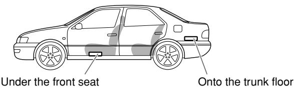
A Mount this unit on a firm surface, such as in the trunk or under the front seat.
- Since heat is generated in the unit, do not mount it near inflammable objects. In addition, mount it in an area that will not prevent the unit from dissipating the heat.
- Do not mount the unit in the places subject to heat: near a radiator, in a glove compartment or in insulated areas such as under a car mat that will prevent the unit from dissipating heat.
- When mounting the unit under the front seat, make sure that adjusting the seat position will not catch any wire of the unit.
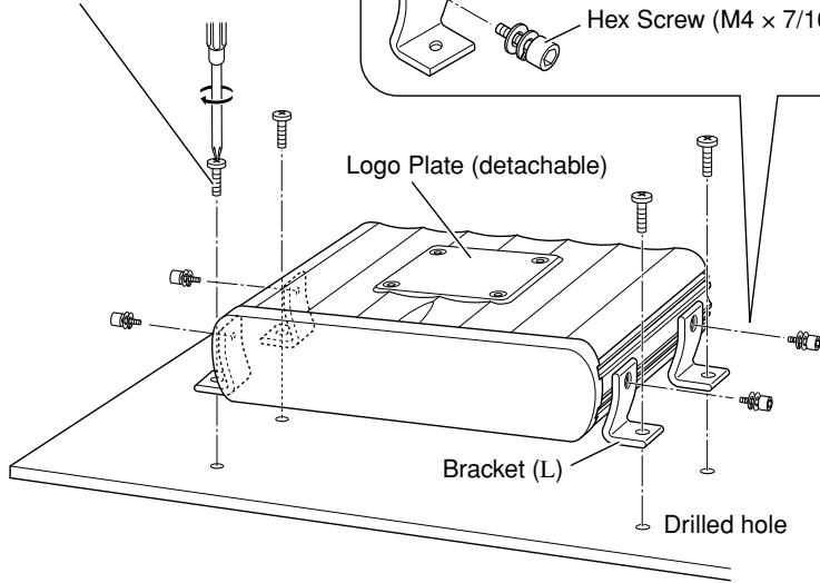
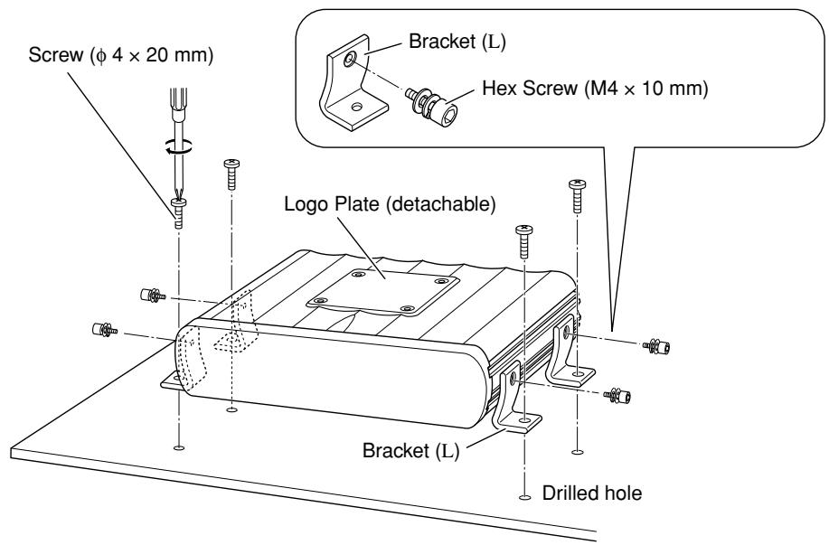
B When mounting this unit, be sure to use the provided screws. If any other screws are used, there is a risk of loosening the unit or damaging parts inside it.
- Before drilling holes in the trunk to install the unit, make sure that there is a sufficient space under the trunk so that you do not drill holes in the fuel tank, etc.
- To detach and rotate the Logo Plate, use the provided hex wrench (3 mm).
Screw (Dia. 3/16 inch (4 mm)
× 13/16 inch (20 mm))
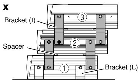
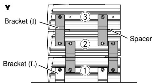
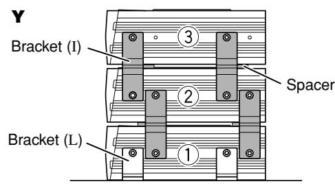
C When you use more than one KS-AR8000 series amplifier, you can pile up to three of them using the provided brackets and hex screws in two ways, X or Y.
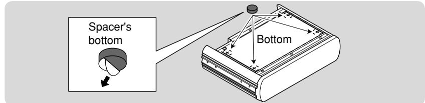
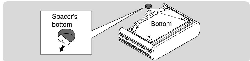
1 Attach the provided spacers to the bottom of the amplifier (② and ③).
2 Fix the amplifiers on both sides with the brackets (I) as illustrated.
- Be sure to mount the lowest amplifier (①) as illustrated on .
- Before piling amplifiers as X , first make the connections for the power supply (see "POWER SUPPLY" below) and speakers (see "SPEAKER CONNECTIONS" on page 2).
Side of the unit
POWER SUPPLY
CAUTION
To prevent short circuits while making connections, keep the battery's negative terminal disconnected.
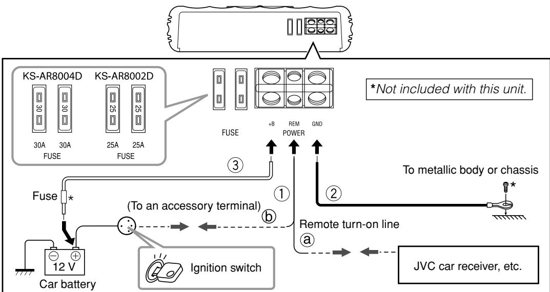
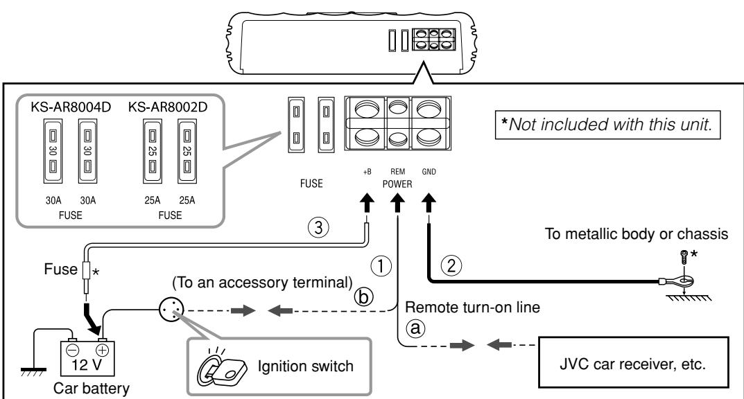
① Remote turn-on line (not included with this unit)
⑧ When you use a JVC car receiver with a remote lead, connect to the remote lead.
6 When you connect a unit without a remote lead, connect to the accessory circuit of the car which is activated by the ignition switch. In this case, noise may occur when the car receiver is turned on or off. To avoid this noise, do not turn on or off the car receiver itself. You can turn on or off the car receiver along with the on/off operation of the ignition switch.
② Ground lead (not included with this unit)
③ Power cord (not included with this unit)
-
When using a power cord, be sure to add the appropriate fuse near the battery as shown.
-For KS-AR8004D: 40 A
-For KS-AR8002D:30 A -
Connect to the battery's “⊕” terminal only after all the other connections have been made.
Note
If the Status lamp (see “CONTROLS” on page 3) lights in red, it indicates incorrect speaker wiring or connections. In this case, see “TROUBLESHOOTING” on page 3. Be sure to correct the speaker wiring and other connections.
TERMINAL CONNECTIONS
The appropriate wire gauge for each terminal is as follows.
-
POWER terminals:
-
+B and GND: AWG 8 to AWG 4 (The cross section is about 8mm^2 to 21mm^2 .)
REM: AWG 18 to AWG 8 (The cross section is about 0.8mm^2 to 8mm^2 .) -
SPEAKER OUTPUT terminals:
AWG 18 to AWG 8 (The cross section is about 0.8mm^2 to 8mm^2 .)
If you have any questions regarding the thickness of the power cord, etc., consult your nearest JVC car audio dealer.
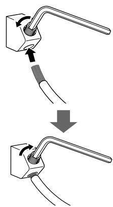
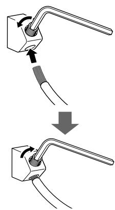
1 Peel off the insulating vinyl cover of a lead to expose the conductor inside.
- The exposed conductor should be 5/16 inch (7 mm) to 7/16 inch (10 mm) long.
- If shorter, it may cause poor conductivity.
- If longer, it may cause a short circuit.
2 Loosen the hex screw in a terminal with the provided hex wrench and insert the conductor into the terminal.
- Use the appropriate hex wrench for each terminal.
- 4 mm: +B and GND terminals
- 3 mm: REM and SPEAKER OUTPUT terminals
3 Fix the hex screw again to secure the conductor.
Make sure to comply with the following notes:
- Be sure not to connect the “ ” terminals of the speakers to a common point.
- If the same lead is used for both left/right or front/rear speaker wirings, this unit cannot be used.
Always use independent leads for each speaker. In this case, redo the wiring. - Use speakers with an impedance of 2 to 8 (4 to 8 : when used in Bridge Mode).
- Use speakers which have sufficient capacity for the unit.
For KS-AR8004D:
When you connect 4 speakers to the unit, down mixed signals (front and rear) are emitted
through the PRE OUT jacks.
For KS-AR8002D:
Incoming signals are emitted through the PRE OUT jacks.
SPEAKER CONNECTIONS
Connection varies depending on the number of the speakers used in your car. Select the appropriate connection referring to the following diagrams.
Before connecting:
- Securely connect all the parts. If the connections are loose, due to contact resistance etc., heat will break out and may cause an accident. Secure and cover the cords with insulating tape and run them under the car mats.
KS-AR8004D

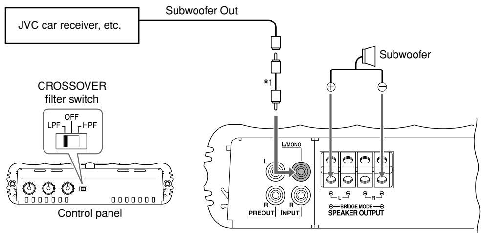
2-speaker system plus subwoofer—Bridge Mode*2

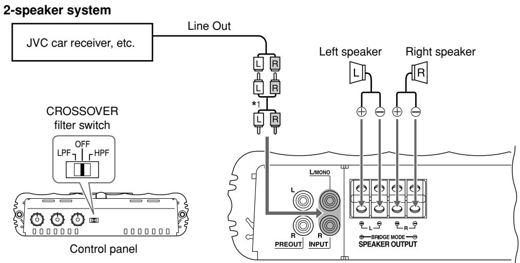
2-speaker system—Bridge Mode*2
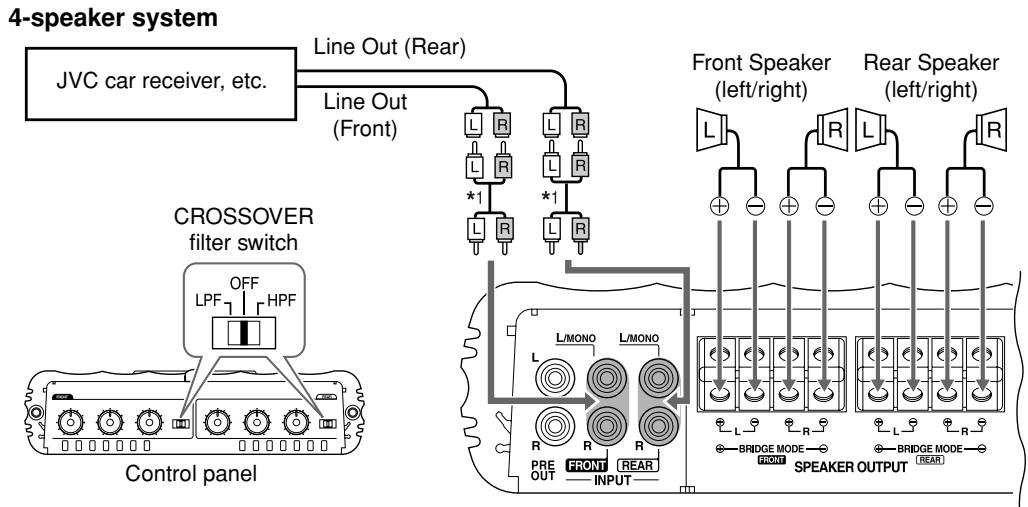
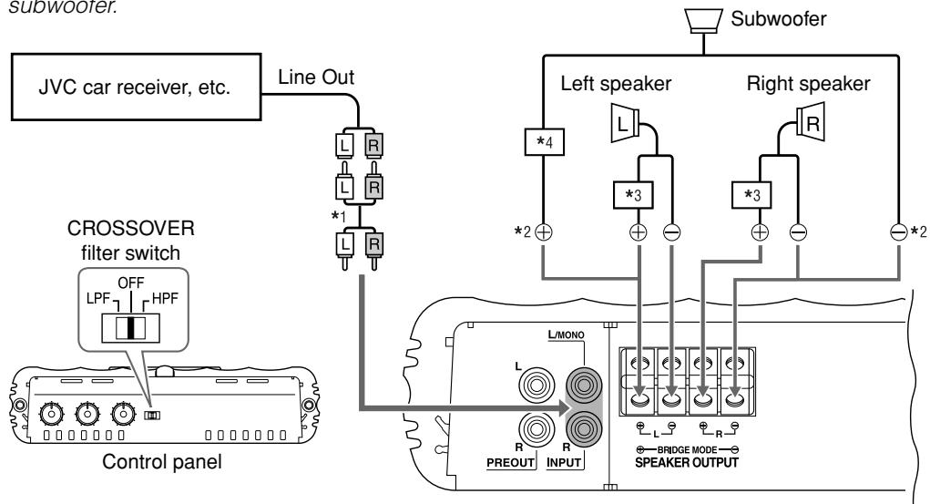
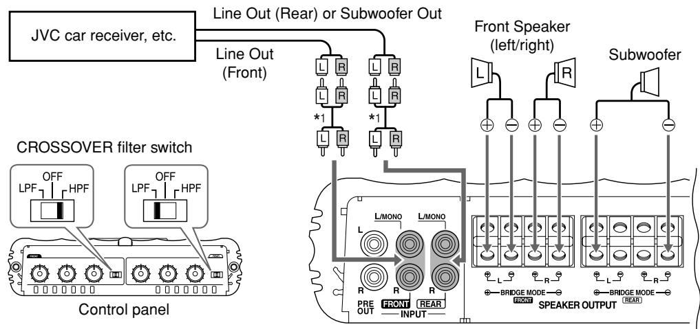
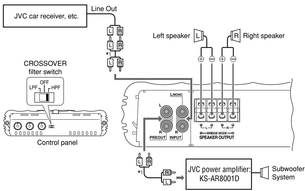
4-speaker system plus subwoofer (PRE OUT)
Down mixed signals are emitted through the PRE OUT jacks.
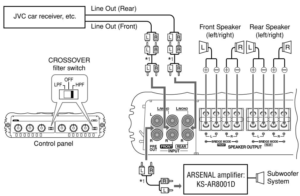
Connect the Line Output from the receiver to the INPUT jacks on this unit using RCA pin cords (not included with this unit).
- Be sure to adjust the CROSSOVER filter switch as illustrated on the following diagrams. (See also "CONTROLS" on page 3.)
Note
Do not adjust the CROSSOVER filter switch while the unit is turned on.
KS-AR8002D
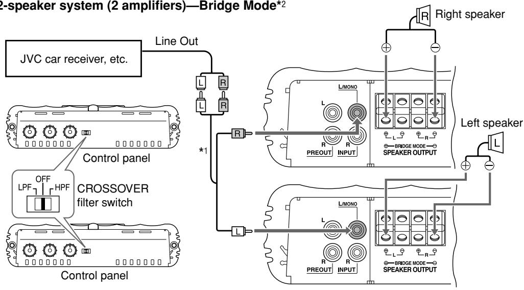
2-speaker system (2 amplifiers)—Bridge Mode*2

Subwoofer system (5.1channel receiver)—Bridge Mode*2

2-speaker system plus subwoofer (PRE OUT)
^1 RCA pin cords (not included with this unit)
2 Bridge Mode: Be sure to connect the line output from the receiver to the left (L/MONO) jack on this unit.
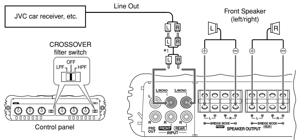
KS-AR8002D
2-speaker system plus subwoofer (1 amplifier)
The minimum impedance should be 4 for each of the left and right speakers, and the subwoofer.
^1 RCA pin cord (not included with this unit)
^ 2 Bridge wiring
^3 Use a High-pass crossover (not included with this unit).
*4 Use a Low-pass crossover (not included with this unit).
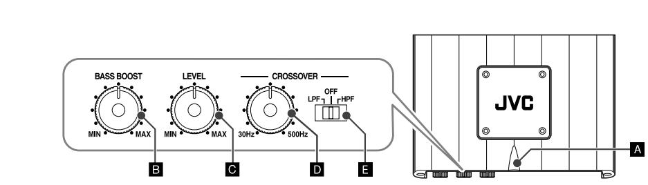
CONTROLS
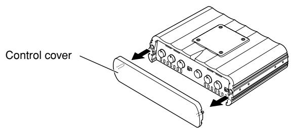
To operate the following controls, detach the control cover. Attach it again after operation.

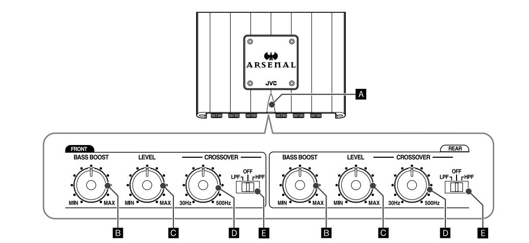
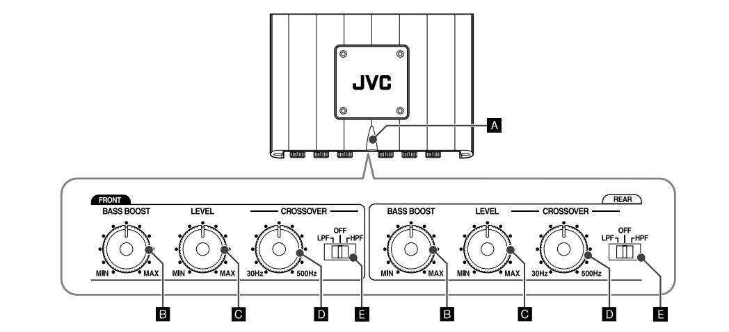
The illustration above is for KS-AR8004D.
KS-AR8004D
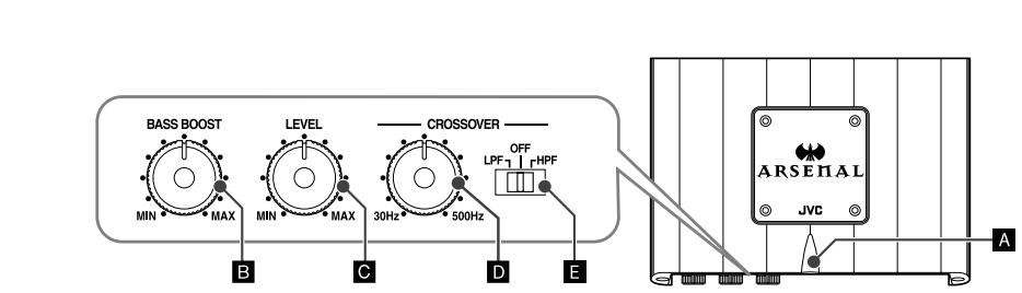
KS-AR8002D
A Status lamp
The lamp normally lights in blue while the unit is turned on.
- When the lamp does not light
- When the lamp lights in red
- When the lamp lights in violet frequently
- It indicates there may be a problem. See "TROUBLESHOOTING" on the right column.
B BASS BOOST controller
Turning this boosts the 45Hz frequency within the range of 0 dB to +18 dB. Adjust the level while listening to the sound. This control is preset to MIN when the unit is shipped.
c Input LEVEL controller
The input level can be adjusted with this control when this unit is connected to other source equipment. Adjust the level while listening to the sound. This control is preset to MIN when the unit is shipped.
CROSSOVER frequency controller
Turning this adjusts the cutoff frequency within the range of 30Hz to 500Hz . Adjust the level while listening to the sound. This control is preset to 30Hz when the unit is shipped.
CROSSOVER filter switch
OFF: Normally, set to this position. The switch is preset to this position when the unit is shipped.
LPF: Set to this position when you want to turn on the LPF (Low-Pass Filter) switch (the Low-Pass Filter transmits frequencies lower than the cutoff frequency).
HPF: Set to this position when you want to turn on the HPF (High-Pass Filter) switch (the High-Pass Filter transmits frequencies higher than the cutoff frequency).
TROUBLESHOOTING
For more details, consult your JVC car audio dealer.
The Status lamp does not light.
- Change the fuses if the current one is blown.
- Confirm the connections for the power supply (see "POWER SUPPLY" on page 1).
- Connect the ground lead securely to a metal part of the car.
- Turn on the equipment connected to this unit
- Use a relay if your system employs so many amplifiers.
- Confirm the battery voltage (11 V to 16 V).
The Status lamp lights in red and/or the unit heats up abnormally.
- Use speakers of a suitable impedance.
- Correct the speaker wirings if they are short-circuited.
- Leave the unit turned off for a while to cool it down.
The Status lamp lights in violet frequently. (Clipping*)
- Lower the input level with the Input LEVEL controller until the lamp lights in violet a few times.
- It means that the amplifier circuits are overloaded and the sound may distort due to too much input from the car receiver.
No sound is heard.
- Confirm the connections for the power supply (see "POWER SUPPLY" on page 1).
- Connect the RCA pin cords to the INPUT jacks.
- Confirm the speaker wirings and the position of the CROSSOVER filter switch (See "SPEAKER CONNECTIONS" on page 2).
Alternator noise is heard.
- Keep the leads of the POWER terminals away from the RCA pin cords.
- Keep the RCA pin cords away from other electrical cables in the car.
- Connect the ground lead securely to a metal part of the car.
- Make sure the negative speaker leads do not touch the car chassis.
- Replace the plugs or use plugs with load resistors.
- Connect a bypass capacitor across the accessory switches (horn, fan, etc.)
Noise is made when you connect the unit to an AM tuner.
- Move all the leads of this unit away from the antenna lead.
SPECIFICATIONS
| Power Output | KS-AR8004D: 120 W RMS x 4 channels at 4 Ω and ≤ 1% THD + N KS-AR8002D: 150 W RMS x 2 channels at 4 Ω and ≤ 1% THD + N |
| Signal-to-Noise Ratio | 80 dBA (reference: 1 W into 4 Ω) |
| Maximum Power Output | 600 W |
| Load Impedance | 4 Ω (Normal mode: 2 Ω to 8 Ω allowance) (Bridge Mode: 4 Ω to 8 Ω allowance) |
| Frequency Response | 5 Hz to 40 kHz* (+0, -3 dB) * Subsonic filter cuts off extremely low frequency signals less than 18 Hz. |
| Input Sensitivity/Impedance | 2 V /44 kΩ (0.3 V to 6 V, variable) |
| Distortion | Less than 0.01% (at 1 kHz) |
| Power Requirement | DC 14.4 V (11 V to 16 V allowance) |
| Grounding system | Negative ground |
| Dimensions (W×H×D) | 9-7/8 inch × 2-1/2 inch × 7-3/16 inch (250 mm × 62 mm × 182 mm) |
| Mass (approx.) | KS-AR8004D: 6.2 lbs. (2.8 kg) KS-AR8002D: 5.8 lbs. (2.6 kg) |
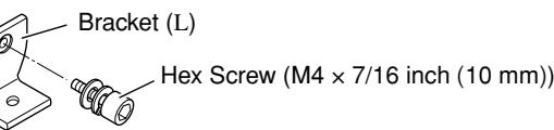
| Accessories | Screw (Dia. 3/16 inch (4 mm) × 13/16 inch (20 mm)) × 4 Hex Screw (M4 × 7/16 inch (10 mm)) × 8 Hex wrench 4 mm × 1 3 mm × 1 Spacer × 4 Bracket L × 4 I × 4 |
Design and specifications are subject to change without notice.

ENGLISH
Thank you for purchasing a JVC product. Please read all instructions carefully before operation, to ensure your complete understanding and to obtain the best possible performance from the unit.
For safety....
- Do not raise the volume level too much, as this will block outside sounds, making driving dangerous.
- Stop the car before performing any complicated operations.
CAUTIONS AND NOTES
This unit is designed to operate on 12 V DC, NEGATIVE ground electrical systems.
- This unit uses BTL (Balanced Transformerless) amplifier circuitry, i.e., floating ground system, so comply with the following:
Do not connect the “ ” terminals of the speakers to each other.
Do not connect the “ ” terminals of the speakers to the metal body or chassis. - Cover the unused terminals with insulating tape to prevent them from short circuiting.
- When an extension lead is used, it should be as thick and short as possible; connect it firmly with insulating tape.
- Be sure to leave an appropriate space between the antenna (aerial) and the wires of this unit.
- When replacing the fuse, use a 30 A fuse for KS-AR8004D or a 25 A fuse for KS-AR8002D.
- Do not let pebbles, sand or metallic objects get inside the unit.
- To keep the heat dissipation mechanism running effectively, wipe the accumulated dust periodically.
- Listening to the tape, radio, CD or Digital Audio Player, etc. with the volume set at a high level for a long period of time will exhaust the battery, while the engine is turned off or while the engine is idling.
- This unit becomes very hot. Be careful not to touch the unit not only when using but for a while after using.
DO NOT disassemble the units since there are no user serviceable parts inside.
INSTALLATION
The following illustration shows a typical installation. However, you should make adjustments corresponding to your specific car. If you have any questions or require information regarding installation kits, consult your "JVC IN-CAR ENTERTAINMENT" car audio dealer or a company supplying the kits.
A Mount this unit on a firm surface, such as in the trunk or under the front seat.
- Since heat is generated in the unit, do not mount it near inflammable objects. In addition, mount it in an area that will not prevent the unit from dissipating the heat.
- Do not mount the unit in the places subject to heat: near a radiator, in a glove compartment or in insulated areas such as under a car mat that will prevent the unit from dissipating heat.
- When mounting the unit under the front seat, make sure that adjusting the seat position will not catch any wire of the unit.

Under the front seat
Onto the trunk floor
B When mounting this unit, be sure to use the provided screws. If any other screws are used, there is a risk of loosening the unit or damaging parts inside it.
- Before drilling holes in the trunk to install the unit, make sure that there is a sufficient space under the trunk so that you do not drill holes in the fuel tank, etc.
- To detach and rotate the Logo Plate, use the provided hex wrench (3 mm).
C When you use more than one KS-AR8000 series amplifier, you can pile up to three of them using the provided brackets and hex screws in two ways, X or Y.
1 Attach the provided spacers to the bottom of the amplifier (② and ③).
2 Fix the amplifiers on both sides with the brackets (I) as illustrated.
- Be sure to mount the lowest amplifier (①) as illustrated on B.
- Before piling amplifiers as X , first make the connections for the power supply (see
"POWER SUPPLY" below) and speakers (see "SPEAKER CONNECTIONS" on page 2).

Side of the unit
POWER SUPPLY
CAUTION
To prevent short circuits while making connections, keep the battery's negative terminal disconnected.
① Remote turn-on line (not included with this unit)
⑧ When you use a JVC car receiver with a remote lead, connect to the remote lead.
6 When you connect a unit without a remote lead, connect to the accessory circuit of the car which is activated by the ignition switch. In this case, noise may occur when the car receiver is turned on or off. To avoid this noise, do not turn on or off the car receiver itself. You can turn on or off the car receiver along with the on/off operation of the ignition switch.
② Ground lead (not included with this unit)
③ Power cord (not included with this unit)
-
When using a power cord, be sure to add the appropriate fuse near the battery as shown.
-For KS-AR8004D: 40 A
-For KS-AR8002D:30 A -
Connect to the battery's “⊕” terminal only after all the other connections have been made.
Note
If the Status lamp (see “CONTROLS” on page 3) lights in red, it indicates incorrect speaker wiring or connections. In this case, see “TROUBLESHOOTING” on page 3. Be sure to correct the speaker wiring and other connections.
TERMINAL CONNECTIONS
The appropriate wire gauge for each terminal is as follows.
-
POWER terminals:
-
+B and GND: Cross section of 8mm^2 to 21mm^2
REM: Cross section of 0.8mm^2 to 8mm^2
- SPEAKER OUTPUT terminals:
Cross section of 0.8mm^2 to 8mm^2
If you have any questions regarding the thickness of the power cord, etc., consult your nearest "JVC IN-CAR ENTERTAINMENT" car audio dealer.
1 Peel off the insulating vinyl cover of a lead to expose the conductor inside.
- The exposed conductor should be 7mm to 10mm long.
- If shorter, it may cause poor conductivity.
- If longer, it may cause a short circuit.
2 Loosen the hex screw in a terminal with the provided hex wrench and insert the conductor into the terminal.
- Use the appropriate hex wrench for each terminal.
- 4 mm: +B and GND terminals
- 3 mm: REM and SPEAKER OUTPUT terminals
3 Fix the hex screw again to secure the conductor.
Make sure to comply with the following notes:
- Be sure not to connect the “ ” terminals of the speakers to a common point.
- If the same lead is used for both left/right or front/rear speaker wirings, this unit cannot be used.
Always use independent leads for each speaker. In this case, redo the wiring. - Use speakers with an impedance of 2 to 8 (4 to 8 : when used in Bridge Mode).
- Use speakers which have sufficient capacity for the unit.
For KS-AR8004D:
When you connect 4 speakers to the unit, down mixed signals (front and rear) are emitted
through the PRE OUT jacks.
For KS-AR8002D:
Incoming signals are emitted through the PRE OUT jacks.
SPEAKER CONNECTIONS
Connection varies depending on the number of the speakers used in your car. Select the appropriate connection referring to the following diagrams.
Before connecting:
- Securely connect all the parts. If the connections are loose, due to contact resistance etc., heat will break out and may cause an accident. Secure and cover the cords with insulating tape and run them under the car mats.

KS-AR8004D
2-speaker system plus subwoofer—Bridge Mode*2
2-speaker system—Bridge Mode*2
4-speaker system plus subwoofer (PRE OUT)
Down mixed signals are emitted through the PRE OUT jacks.

Connect the Line Output from the receiver to the INPUT jacks on this unit using RCA pin cords (not included with this unit).
- Be sure to adjust the CROSSOVER filter switch as illustrated on the following diagrams. (See also "CONTROLS" on page 3.)
Note
Do not adjust the CROSSOVER filter switch while the unit is turned on.

KS-AR8002D

2-speaker system (2 amplifiers)—Bridge Mode*2
Subwoofer system (5.1channel receiver)—Bridge Mode*2
2-speaker system plus subwoofer (PRE OUT)
^1 RCA pin cords (not included with this unit)
2 Bridge Mode: Be sure to connect the line output from the receiver to the left (L/MONO) jack on this unit.
To operate the following controls, detach the control cover. Attach it again after operation.
The illustration above is for KS-AR8004D.
KS-AR8004D
KS-AR8002D
A Status lamp
The lamp normally lights in blue while the unit is turned on.
- When the lamp does not light
- When the lamp lights in red
-
When the lamp lights in violet frequently
-
It indicates there may be a problem. See "TROUBLESHOOTING" on the right column.
B BASS BOOST controller
Turning this boosts the 45Hz frequency within the range of 0 dB to +18 dB. Adjust the level while listening to the sound. This control is preset to MIN when the unit is shipped.
C Input LEVEL controller
The input level can be adjusted with this control when this unit is connected to other source equipment. Adjust the level while listening to the sound. This control is preset to MIN when the unit is shipped.
CROSSOVER frequency controller
Turning this adjusts the cutoff frequency within the range of 30Hz to 500Hz . Adjust the level while listening to the sound. This control is preset to 30Hz when the unit is shipped.
CROSSOVER filter switch
OFF: Normally, set to this position. The switch is preset to this position when the unit is shipped.
LPF: Set to this position when you want to turn on the LPF (Low-Pass Filter) switch (the Low-Pass Filter transmits frequencies lower than the cutoff frequency).
HPF: Set to this position when you want to turn on the HPF (High-Pass Filter) switch (the High-Pass Filter transmits frequencies higher than the cutoff frequency).
TROUBLESHOOTING
For more details, consult your "JVC IN-CAR ENTERTAINMENT" car audio dealer.
The Status lamp does not light.
- Change the fuses if the current one is blown.
- Confirm the connections for the power supply (see "POWER SUPPLY" on page 1).
- Connect the ground lead securely to a metal part of the car.
- Turn on the equipment connected to this unit.
- Use a relay if your system employs so many amplifiers.
- Confirm the battery voltage (11 V to 16 V).
The Status lamp lights in red and/or the unit heats up abnormally.
- Use speakers of a suitable impedance.
- Correct the speaker wirings if they are short-circuited.
- Leave the unit turned off for a while to cool it down.
The Status lamp lights in violet frequently. (Clipping*)
- Lower the input level with the Input LEVEL controller until the lamp lights in violet a few times.
- It means that the amplifier circuits are overloaded and the sound may distort due to too much input from the car receiver.
No sound is heard.
- Confirm the connections for the power supply (see "POWER SUPPLY" on page 1).
- Connect the RCA pin cords to the INPUT jacks.
- Confirm the speaker wirings and the position of the CROSSOVER filter switch (See "SPEAKER CONNECTIONS" on page 2).
Alternator noise is heard.
- Keep the leads of the POWER terminals away from the RCA pin cords.
- Keep the RCA pin cords away from other electrical cables in the car.
- Connect the ground lead securely to a metal part of the car.
- Make sure the negative speaker leads do not touch the car chassis.
- Replace the plugs or use plugs with load resistors.
- Connect a bypass capacitor across the accessory switches (horn, fan, etc.)
Noise is made when you connect the unit to an AM (MW/LW) tuner.
- Move all the leads of this unit away from the antenna (aerial) lead.
SPECIFICATIONS
| Maximum Power Output | 600 W |
| RMS Power Output | KS-AR8004D: 120 W RMS x 4 channels at 4 Ω and ≤ 1% THD + N KS-AR8002D: 150 W RMS x 2 channels at 4 Ω and ≤ 1% THD + N |
| Load Impedance | 4 Ω (Normal mode: 2 Ω to 8 Ω allowance) (Bridge Mode: 4 Ω to 8 Ω allowance) |
| Frequency Response | 5 Hz to 40 kHz* (+0, -3 dB) * Subsonic filter cuts off extremely low frequency signals less than 18 Hz. |
| Input Sensitivity/Impedance | 2 V /44 kΩ (0.3 V to 6 V, variable) |
| Distortion | Less than 0.01% (at 1 kHz) |
| Signal-to-Noise Ratio | 80 dBA (reference: 1 W into 4 Ω) |
| Power Requirement | DC 14.4 V (11 V to 16 V allowance) |
| Grounding system | Negative ground |
| Dimensions (W×H×D) | 250 mm × 62 mm × 182 mm |
| Mass (approx.) | KS-AR8004D: 2.8 kg KS-AR8002D: 2.6 kg |
| Accessories | Screw (φ 4 × 20 mm) × 4 Hex Screw (M4 × 10 mm) × 8 Hex wrench 4 mm × 1 3 mm × 1 Spacer × 4 Bracket L × 4 I × 4 |
Design and specifications are subject to change without notice.
Information for Users on Disposal of Old Equipment

This symbol indicates that the product with this symbol should not be disposed as general household waste at its end-of-life. If you wish to dispose of this product, please do so in accordance with applicable national legislation or other rules in your country and municipality. By disposing of this product correctly, you will help to conserve natural resources and will help prevent potential negative effects on the environment and human health.
This symbol is only valid in the European Union.
Dear Customer,
This apparatus is in conformance with the valid European directives and standards regarding electromagnetic compatibility and electrical safety.
European representative of Victor Company of Japan, Limited is: JVC Technology Centre Europe GmbH
Company name changed in:
JVC Technical Services Europe GmbH
Postfach 10 05 52
61145 Friedberg
Germany