02RV2 - Table de mixage numérique YAMAHA - Notice d'utilisation et mode d'emploi gratuit
Retrouvez gratuitement la notice de l'appareil 02RV2 YAMAHA au format PDF.

| Type de produit | Table de mixage numérique |
| Marque | YAMAHA |
| Modèle | 02RV2 (02R Version 2) |
| Nombre de canaux d'entrée | 40 canaux (24 entrées analogiques + 8 entrées numériques via cartes optionnelles + 8 retours d'effets) |
| Entrées analogiques | 24 entrées équilibrées (8 avec connecteurs XLR et prises phone, 16 avec prises phone) |
| Sorties analogiques | 2 sorties stéréo principales, 6 sorties auxiliaires, sorties studio et monitoring |
| Entrées/sorties numériques | AES/EBU et IEC958 (stéréo), cartes optionnelles pour formats ADAT, TDIF, Yamaha |
| Bus de mixage | 8 bus de sortie, 8 bus auxiliaires, bus stéréo principal |
| Traitement interne | 32 bits DSP propriétaire, dynamique > 190 dB |
| Convertisseurs A/N | 20 bits, suréchantillonnage 64x |
| Convertisseurs N/A | 20 bits, suréchantillonnage 8x (sorties principales), 18 bits 8x (sorties aux) |
| Égalisation | 4 bandes paramétriques par canal, courbes EQ affichables, bibliothèque EQ (32 préréglages + 96 utilisateur) |
| Dynamique | Compresseur, expandeur, gate, ducking, compander; 50 processeurs, bibliothèque (40 préréglages + 88 utilisateur) |
| Effets internes | 2 processeurs stéréo multipièges (réverb, delay, chorus, etc.), bibliothèque (40 préréglages + 88 utilisateur) |
| Automation | Automix dynamique basé sur timecode, 96 mémoires de scène, automix en temps réel et édition d'événements |
| Faders motorisés | 100 mm, rappel automatique, groupes de faders et de mute |
| Affichage | Écran graphique 320x240 pixels, rétroéclairage fluorescent |
| Entretien et nettoyage | Débrancher l'alimentation avant nettoyage ; ne pas utiliser d'huile ou de graisse sur les faders ; nettoyage interne par un technicien agréé une fois par an |
| Sécurité | Ne pas obstruer les ventilations, éviter l'humidité, utiliser une prise de courant adaptée, ne pas ouvrir le boîtier |
| Alimentation | 100-240 V CA, 50/60 Hz (adaptation automatique) |
| Poids | Environ 22 kg |
| Dimensions | Environ 482 mm (largeur) x 310 mm (hauteur) x 600 mm (profondeur) |
FOIRE AUX QUESTIONS - 02RV2 YAMAHA
Questions des utilisateurs sur 02RV2 YAMAHA
0 question sur cet appareil. Repondez a celles que vous connaissez ou posez la votre.
Poser une nouvelle question sur cet appareil
Téléchargez la notice de votre Table de mixage numérique au format PDF gratuitement ! Retrouvez votre notice 02RV2 - YAMAHA et reprennez votre appareil électronique en main. Sur cette page sont publiés tous les documents nécessaires à l'utilisation de votre appareil 02RV2 de la marque YAMAHA.
MODE D'EMPLOI 02RV2 YAMAHA
O2R
DIGITAL RECORDING CONSOLE
Version 2
OWNER'S MANUAL

FCC INFORMATION (U.S.A.)
- IMPORTANT NOTICE: DO NOT MODIFY THIS UNIT!
This product, when installed as indicated in the instructions contained in this manual, meets FCC requirements. Modifications not expressly approved by Yamaha may void your authority, granted by the FCC, to use the product.
-
1t be used. Follow all installation instructions. Failure to follow instructions could void your FCC authorization to use this product in the USA.
-
NOTE: This product has been tested and found to comply with the requirements listed in FCC Regulations, Part 15 for Class "B" digital devices. Compliance with these requirements provides a reasonable level of assurance that your use of this product in a residential environment will not result in harmful interference with other electronic devices. This equipment generates/uses radio frequencies and, if not installed and used according to the instructions found in the users manual, may cause interference harmful to the operation of other electronic devices. Compliance with FCC regulations does not guarantee that interference will not occur in all installations. If this product is found to be the source of interference, which can be determined by turning the unit "OFF" and "ON", please try to eliminate the problem by using one of the following measures:
Relocate either this product or the device that is being affected by the interference.
Utilize power outlets that are on different branch (circuit breaker or fuse) circuits or install AC line filter/s.
In the case of radio or TV interference, relocate/reorient the antenna. If the antenna lead-in is 300 ohm ribbon lead, change the lead-in to coaxial type cable.
If these corrective measures do not produce satisfactory results, please contact the local retailer authorized to distribute this type of product. If you can not locate the appropriate retailer, please contact Yamaha Corporation of America, Electronic Service Division, 6600 Orangethorpe Ave, Buena Park, CA 90620
- This applies only to products distributed by YAMAHA CORPORATION OF AMERICA.
IMPORTANT NOTICE FOR THE UNITED KINGDOM
Connecting the Plug and Cord
WARNING: THIS APPARATUS MUST BE EARTHED
IMPORTANT: The wires in this mains lead are coloured in accordance with the following code:
GREEN-AND-YELLOW : EARTH
BLUE : NEUTRAL
BROWN : LIVE
As the colours of the wires in the mains lead of this apparatus may not correspond with the coloured markings identifying the terminals in your plug, proceed as follows:
The wire which is coloured GREEN and YELLOW must be connected to the terminal in the plug which is marked by the letter E or by the safety earth symbol or coloured GREEN and YELLOW.
The wire which is coloured BLUE must be connected to the terminal which is marked with the letter N or coloured BLACK.
The wire which is coloured BROWN must be connected to the terminal which is marked with the letter L or coloured RED.
- This applies only to products distributed by YAMAHA KEMBLE MUSIC (U.K.) LTD.
ADVARSEL!
Lithiumbatteri-Eksplosionsfare ved fejtagit handtering. Udskiftning ma kun ske med batteri af samme fabrikat og type. Lever det brugte batteri tilbage til leverandoren.
WARNING
Explosionsfara vid felaktigt batterbyte. Använd samma battertyp aller en ekvivalent typ som rekommenderas av apparattillverkaren.
Kassera anvant batteri enligt fabrikantens instruktion.
VAROITUS
Paristo voi rajähtä,Jos se on virheellisesti asennettu. Vaihda paristo ainoastaan laitevalmistajan susittelemaan typpin. Havitta käytetty paristo valmistajan ohjeiden mukaisesti.
NEDERLAND
- Dit apparaat bevat een lithium batterij voor geheugen backup.
Raadpleeg uw leverancier over de verwijdering van de batterij op het moment dat u het apparaat ann het einde van de levensduur afdankt of de volgende Yamaha Service Afdeiing: Yamaha Music Nederland Service Afdeiing Kanaalweg 18-G, 3526 KL UTRECHT Tel.030-2828425
Gooi de batterij Niet weg, maar lever hem in als KCA.
THE NETHERLANDS
- This apparatus contains a lithium battery for memory backup.
- For the removal of the battery at the moment of the disposal at the end of the service life please consult your retailer or Yamaha Service Center as follows:
Yamaha Music Nederland Service Center
Address: Kanaalweg 18-G, 3526 KL
UTRECHT
Tel: 030-2828425
- Do not throw away the battery. Instead, hand it in as small chemical waste.
Important Information
Please read the following before operating your 02R Digital Recording Console.
Precautions
Installing the 02R
- The unit should be connected only to an AC receptacle of the type described in the owner's manual or as marked on the unit.
- Be careful to prevent the 02R from getting wet; do not allow water to enter the 02R, especially when raining or snowing, or near a body of a water. Otherwise, fire or electrical shock may result.
- Do not block the ventilation holes on the 02R. The 02R has ventilation holes on the top, rear, front and bottom panel to prevent the inside temperature from rising. If the ventilation holes are blocked, the heat will remain inside, resulting in fire. In particular, avoid the following situations:
Do not orient the 02R upside down, face down, or sideways.
Do not place the 02R in a narrow, non-ventilated space, such as in a bookcase or closet. Use a dedicated rack.
- Do not place a table cloth on top of the 02R; do not place the 02R on a carpet or mattress.
- Do not place heavy objects on the power cord. If the cord is damaged, fire or electrical shock may result. In particular, it is possible that one might accidentally place a heavy object on the carpet that covers the cord, or place the 02R on top of a power cord; avoid these situations.
- To allow for the efficient release of heat, maintain a gap of 10cm or more between the rear of the 02R and the wall. Locate the 02R away from other equipment. If the release of heat is insufficient, the heat will remain inside the device, and result in a fire.
- Do not install the 02R in a place where it may be exposed to oil, smoke, or steam (for example, near a cooking table or humidifier). Otherwise, fire or electrical shock may result.
- Do not place the 02R on an unstable surface, such as an unstable bench or slanted surface. Otherwise, the equipment may fall or drop, resulting in injury.
- Do not place the power cord near a heating device. Otherwise, the cord sheath may melt, resulting in fire or electrical shock.
- Do not locate the 02R in a place subject to excessive heat, such as inside a car with all the windows closed, or in direct sunlight. Otherwise, fire may result.
- Do not place the 02R in a place subject to excessive humidity or dust. Otherwise, fire or electrical shock may result.
-
Do not handle the power plug with wet hands. Otherwise, you may receive an electrical shock.
-
When you remove the power plug, be sure to hold the plug. Never pull on the cord. Otherwise, the power cord will become damaged, resulting in fire or electrical shock.
- When relocating the 02R, since the 02R is heavy, make sure that two or more people carry it.
- When you are moving the 02R to another location, first turn off the power switch, remove the power plug from the AC outlet, and remove all cables connected to external devices. Otherwise, the cables may become damaged, resulting in fire or electrical shock.
- The 02R offers superb sonic quality. To ensure the best possible results, you should use the best quality connecting cables that you can afford. Regular maintenance involves keeping all connections clean using a quality contact cleaner.
- Do not place a container with liquid or small metal objects on top of this unit. Liquid or metal objects inside this unit are a fire and electrical shock hazard.
Using the 02R
Do not touch the 02R under the following circumstances:
- If you hear thunder, turn off the power switch and remove the power plug from the AC outlet as soon as possible.
If you fear a lightning hit, and the 02R has been connected to an AC outlet, do not touch the power plug. Otherwise, you may receive an electrical shock. - Do not attempt to modify this equipment. Otherwise, fire or electrical shock may result.
- Do not remove the case of the 02R. Otherwise, electrical shock may result.
If you think the 02R needs to be checked for maintenance or repair, consult your dealer.
- Do not place a container of water, or any small metal object on top of the 02R. If water is spilled or if the metal object falls inside, fire or electrical shock may result. This applies to vases, potted plants, glasses, cosmetic bottles, medicine, etc.
- Do not damage, process, bend, twist, stretch, or heat the power cord. Otherwise, the cord may be damaged, resulting in fire or electrical shock.
- When you are connecting audio devices or speakers to the 02R, make sure that first you turn off the power to all devices to be connected. Refer to the user's guide for each device, and use the specified cable for connection.
- Set the volume level on all the devices to the minimum before turning on the power. Otherwise, an extremely loud noise could damage your hearing.
- If you plan not to use the 02R for a long period of time (such as when you are on vacation), remove the power plug from the AC outlet. Otherwise, a fire could possibly result.
If an abnormality occurs while operating the 02, remove the plug from the AC outlet
- If you notice any abnormality—such as smoke, odor, noise, etc—turn off the power to the 02R immediately, and remove the power plug from the AC outlet. Confirm that the abnormality is no longer present, then consult your dealer for repair. If you continue using the 02R under abnormal conditions, fire or electrical shock may result.
- If a foreign object or water enters inside the equipment, turn off the power to the 02R immediately, remove the power plug from the AC outlet, and consult your dealer for repair. If you continue using the 02R under this condition, fire or electrical shock may result.
- If the power cord is damaged (for example, the it is cut or if the core wire is exposed), ask your dealer for a replacement. If you continue using the 02R under this condition, fire or electrical shock may result.
- If the 02R is dropped, or the cabinet is damaged, turn off the power switch, remove the power plug from the AC outlet, and consult your dealer. If you continue using the 02R under this condition, fire or electrical shock may result.
Maintenance
- Before cleaning the 02R, remove the power plug from the AC outlet for safety. Otherwise, an electrical shock may result.
- An authorized dealer should clean the internal parts of the 02R on a regular basis. If you do not clean them for a long period of time, allowing dust to accumulate inside the equipment, fire or malfunction may result.
Consult your dealer about cleaning and its cost.
The optimum frequency for cleaning is once a year. It is especially effective to clean before a rainy or humid season starts.
- The performance of contact parts—such as switches, the volume encoder, and connectors—deteriorates with use. The degree of deterioration may differ depending on the environment, but the deterioration itself cannot be avoided. To replace the contact parts, consult your dealer.
- Do not apply oil, grease, or a contact repair agent to the faders. Otherwise, the conductivity of the electrical contact point may be affected.
If you think the faders' movement is awkward, refer to "User's Guide" on page 215 for calibration information.
Data backup
Data stored inside the equipment may be destroyed by malfunction or incorrect operation of the equipment. Be sure to save important data to an external MIDI device for backup.
Influences on other electrical devices
This equipment uses many digital circuits, which may cause noise to occur on nearby radio or TV. In this case, relocate the 02R away from those devices.
02R Exclusion of Certain Responsibility
Manufacturer, importer, or dealer shall not be liable for any incidental damages including injury to the person, and/or any other damages caused by improper use or operation of the 02R. Please, read the instructions in this manual.
Copyright
© 1997 Yamaha Corporation. All rights reserved.
No part of the 02R software or its user manuals may be reproduced or distributed in any form or by any means without the prior written authorization of Yamaha Corporation.
Trademarks
ADAT MultiChannel Optical Digital Interface is a trademark and ADAT and Alesis are registered trademarks of Alesis Corporation. Dolby, AC-3, and Pro-Logic are trademarks of Dolby Laboratories Licensing Corporation. Copyright 1992 Dolby Laboratories, Inc. All rights reserved. Pro Tools is a registered trademark of Digidesign or Avid Technology, Inc. Tascam Digital Interface is a trademark and Tascam and TEAC are registered trademarks of TEAC Corporation. All other trademarks and registered trademarks are the property of their respective holders.
Package Contents
Your 02R package contains the following items. If you do not have them all, please contact your Yamaha dealer.
02R Console
- This Owner's Manual (contains Getting Started Guide and User's Guide)
Important Note About Project Manager
Version 1 of Project Manager is not compatible with the 02R Version 2 and may cause data loss. To obtain Version 2 of Project Manager, contact Zeep in Canada at http://www.zeep.com/ or tel: 514-272-2224 or fax: 514-272-2888. Alternatively, contact your Yamaha dealer for additional information about archiving 02R Version 2 data.
O2R
DIGITAL RECORDING CONSOLE
Version 2
Getting Started Guide
Contents
1 Introduction to the 02R. 1
02R. 2
User Guidelines 3
Installation 3
Top and Rear Panels 4
Features. 5
Key Features. 7
2 Getting Started 13
Basic Assumptions 14
Making the Connections 14
Basic Setup 15
Power ON/OFF. 16
Setting the Synchronization. 16
3 Introductory Recording Tutorial 19
Setting the Input Level 20
Applying EQ 24
Using the EQ Library 30
Panning. 38
4 Secondary Recording Tutorial. 41
Aux Sends. 42
Setting the Aux Send Level 43
Creating a Monitor Mix 45
Applying Effects 46
Recalling and Editing Effects. 49
Patching in a Dynamics Processor 54
Using the Dynamics Library 57
Scene Memories. 62
5 Mixing and Automix 67
What is 02R Automix? 68
Real-time Automix 69
Editing Automix Events. 76
Off-line Automix Editing 81
Using the Automix Library 87
Index 90
1
Introduction to the 02R
In this chapter...
02R. 2
User Guidelines 3
Installation 3
Top and Rear Panels 4
Features. 5
Key Features. 7
02R
From the company that pioneered digital mixing consoles and leads the industry with its acclaimed DSP technology comes the 02R Digital mixing Console—the most advanced digital mixing console in the world. All of Yamaha's experience and innovation has been applied to the 02R, to create a perfect mixer for use with the current generation of modular digital multitrack tape and disk recorders.
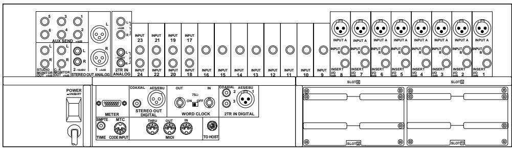
Inputs and Outputs - I/O Cards and Digital Cascade
With the 02R you can record and mix directly to your modular digital multitrack recorder without ever leaving the sonic purity of the digital domain. It is a 40 input channel mixer, each with full dynamic processing and 4-band parametric EQ, plus two stereo internal effects returns. It comes with 24 analog inputs, featuring 20-bit 64-times oversampling analog-to-digital conversion. By adding one of the optional digital I/O cards, you can also have 8 channels of direct digital input. Depending on configuration, up to four cards can be inserted into the 02R. The cards allow you to select from any of the currently used formats (ADAT®, TDIF™, Yamaha, or AES/EBU). The optional cards allow you to route up to 16 outputs directly to your modular digital multitrack recorder. In addition, you can insert a Digital Cascade card into one of the I/O slots, allowing you to connect multiple 02Rs together to create a larger digital mixing system.
Dynamic Automix with Total and Instant Recall
The 02R is a fully dynamic automated mixing console—all referenced to timecode. Its onboard automix system memorizes not just the faders, but a myriad of parameters. Switch individual channels on or off, adjust the EQ or the pan position, change the auxiliary send, and recall any scene memory—automatically. There are 96 internal scene memories which can store every digital mix parameter in a “snapshot” providing instant recall and reset.
Crystal Clarity and Unsurpassed Audio Quality
The 02R features Yamaha's latest generation 32-bit proprietary audio DSP. All of your mix data is processed internally with 32-bit precision. Using the power of the latest generation effects processor chip, it also has a startling range of effects available: shimmering revers, clean, precise delays, flanging and chorus, and other effects are built into this mixer. It also features dynamics processors on all the inputs, allowing you to compress, limit, or gate the signals, giving you unparalleled sonic quality and flexibility. The 02R samples audio at 44.1 kHz or 48 kHz using its internal clock, and can sample at any frequency from 28 kHz to 53 kHz when an external word clock is applied.
RISC Technology
To provide powerful system control and full dynamic automix, the 02R is driven by a RISC technology CPU. With all this power and sonic quality, the 02R will become the heart of your digital recording studio.
User Guides
The 02R is supplied with an Owner's Manual that consists of two guides—a Getting Started Guide and a User's Guide. You should keep this manual handy for future reference.
Getting Started Guide
The Getting Started Guide contains a simple description and a couple of tutorials about digital recording with the 02R to get you started. It also has a tutorial on the automix system.
User's Guide
The User's Guide explains each 02R function in full detail. Use its table of contents to search for general topics and the index to search for specifics. A glossary of related terms is also provided.
Where to Start
If you are unfamiliar with the 02R, you should start with the Getting Started Guide. Read through the section and follow the steps outlined in the tutorials. Refer to the User's Guide when you are more familiar with the 02R and just need the details of how a particular function works. You may also want to refer to the User's Guide for more detailed information while using the Getting Started Guide.
Automix System
Regardless of your level of experience, you should read through the section "Mixing and Automix" on page 67 of the Getting Started Guide. The automix system built into the 02R is unique to this product. Even experienced recording engineers will want to refer to this section to discover how to record and playback entire mixing sessions. You should also refer to the section entitled "Automix" on page 137 of the User's Guide.
Installation
You should locate the 02R on a stable surface. It should be sited so that the display can be easily read from a comfortable position. Leave plenty of access space at the back of the 02R to make the required connections to the other equipment in your digital recording studio.
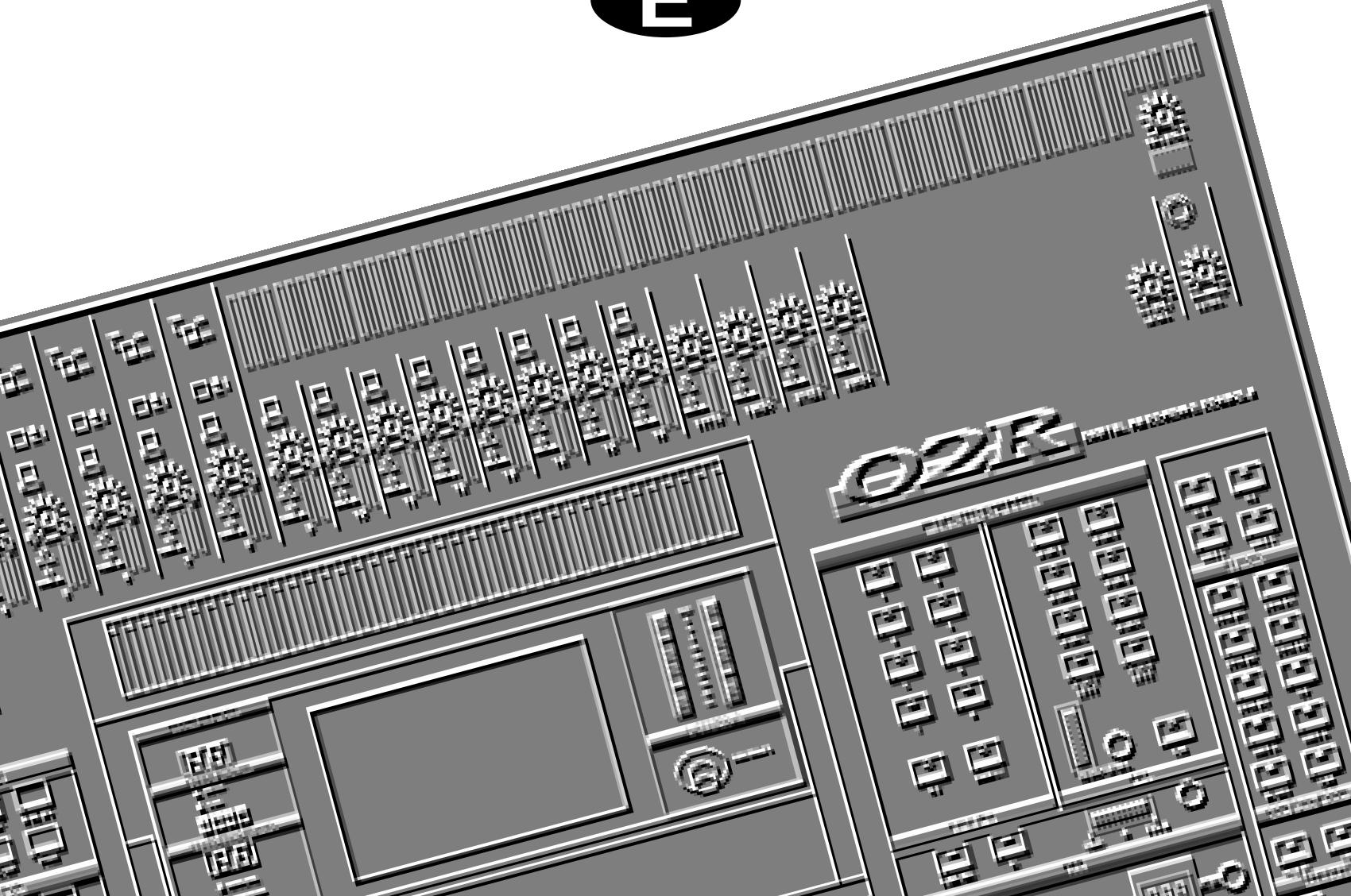
Top and Rear Panels
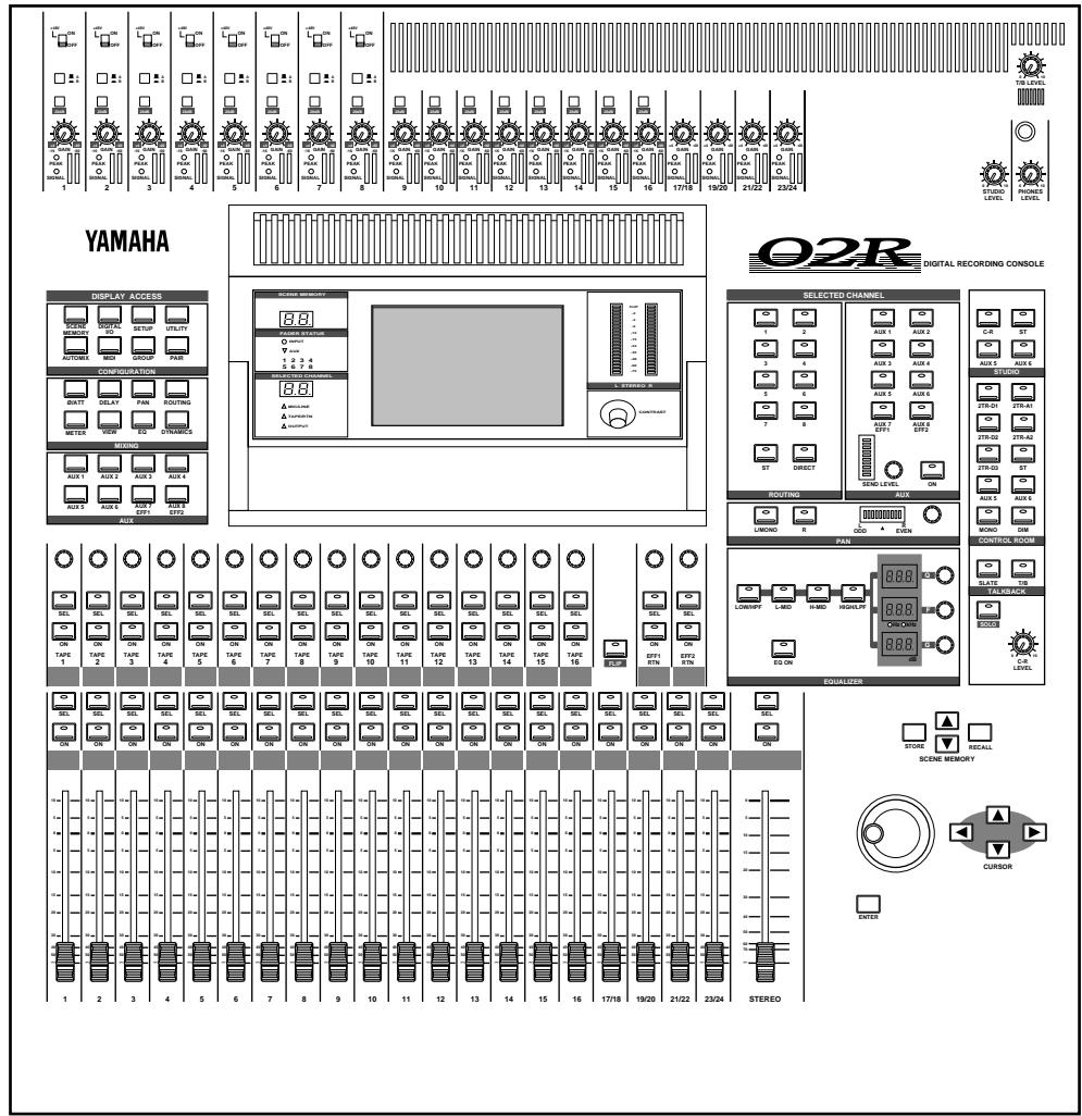
Features
Sonic Specifications
- Linear 20-bit 64-times oversampling A/D convertors
- Linear 20-bit 8-times oversampling D/A convertors
105 dB dynamic range (typical) - 32-bit precision internal processing with a dynamic range of over 190 dB using Yamaha's 32-bit proprietary audio DSP
General Features
40 input channel mixer, with full dynamic processing and 4-band parametric equalization
- Dynamic automix—all referenced to timecode
96 internal scene memories for storing all digital mixer settings
4-band Parametric EQ with sweepable center-frequency from 20Hz to 20kHz and adjustable bandwidth (Q)
- Extensive EQ library
- Comprehensive dynamics processors on each input channel, tape return, and buss and stereo output:
- Compressor
- Expander
Gate/Ducking - Soft and Hard Compander
Dynamics library
- Fully programmable channel settings: phase and attenuation, delay, pan, routing, meters, EQ, and dynamics
- Channel library
- Two internal stereo effects using proprietary processor chip
Effects library
8 output busses, 8 auxiliary send busses, and main stereo mix buss
24 balanced analog inputs (8 channels with either XLR-type or phone connectors)
- Continuously variable gain control
20 dB input pad
- 8 XLR-type inputs with 48V phantom power for condenser microphones
8 analog insert input/output connections
2 analog 2TR IN inputs
2 analog stereo outputs
- 6 analog auxiliary send outputs
- Stereo studio and control room outputs
3 digital 2TR IN inputs
2 digital stereo outputs
- Industry standard AES/EBU or IEC958 Part2 (Consumer) digital inputs and outputs
100 mm motorized faders
- Fader and mute groups for single fader or button control over several faders or channel ON buttons
- Adjacent channel pair function for stereo operation on inputs, tape returns, and auxiliary channels
- Dedicated buttons and controls of the Selected Channel module
Large 320× 240 pixel, FL-backlit, user-friendly graphical display
RISC technology CPU
- SMPTE and MTC synchronization plus full MIDI implementation
Options
Digital I/O cards:
ADAT (CD8-AT)
TASCAM (CD8-TDII)
Yamaha (CD8-Y)
AES/EBU double slot card (CD8-AE)
AES/EBU single slot card (CD8-AE-S)
- Cascade Kit (CD8-CS)
-
Analog I/O cards
-
Analog I/O double slot card (CD8-AD)
-
Analog input single slot card (CD8-AD-S)
-
Automix 1 MB memory expansion (ME4M)
- Meter bridge (MB02)
Wooden side panels (W02SP)
Key Features
This section looks at some of the key features of the 02R, what they mean to you, and some hints about how you can use them.
Dynamic Automix
One of the most demanding jobs of the recording engineer is taking all the raw material produced during a multitrack recording session and mixing it all together into an artistically satisfying master recording. The ability to setup portions of the mix and then have them playback automatically as you work on other portions is probably the most important feature of the 02R.
It has an on-board automix system that memorizes fader positions, switches individual channels on or off, adjusts the EQ or pan positions, and changes the auxiliary sends—all referenced to timecode. It can also record and execute scene memory changes, also referenced to timecode. This allows you to perform an entire mixing session, and then edit individual channel settings until you have achieved the perfect mix.
The 02R allows you to record a mixdown in real-time and then edit the results, either in real-time or by using one of the event editors. You can select single parameters of the mixer to edit—for example, just enable the faders for one pass as you create your mixdown.
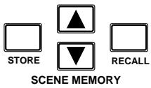
Scene Memories
The 02R has 96 internal scene memories each of which is a snapshot of all the digital settings of the mixer (a mix scene). Each can be named for easy identification. They can be stored and later recalled instantly.
If you work on several projects at one time, you can store the current mixer settings in a scene memory so when you return to that project, you can start immediately from where you left off. When you are working on a mixdown, the ability to recall mixer scenes can speed the process and allows for accurate repetition of the various parts of the mix. When you use the 02R for sound reinforcement applications, the ability to recall mix scenes can make light work of night-after-night sound checks.
Storing the mixer settings to a scene memory is a simple matter of pressing the [STORE] button and confirming the request.
Note: You can customize your 02R to perform the storage operation without confirmation. See "Preferences" on page 198 of the User's Guide for more details.
Recalling the scene is even easier—just press the [RECALL] button. You should be careful that your scene memories flow into each other smoothly. The instant recall means that you can have very abrupt level changes or the unexpected intrusion of a very loud channel.
Note: The 02R allows you to have programmable fades between scene memories. The only thing you need to watch is the sudden sound of a channel being switched on. Even then, if the original channel level was set to - dB, you should have no problems. See "Fade Time" on page 136 of the User's Guide.
Large Graphical Display
The heart of the 02R user interface is the large graphical display located in the center of the console. Using the Display Access controls, you can gain immediate access to the features of the mixer—clearly displayed on the 320 × 240 pixel, FL-backlit, user-friendly graphical display. Virtual control modules are shown on the display, allowing you to adjust almost any digital parameter anywhere in the system.
As well as displaying parameter values numerically, faders, rotary controls, and push buttons are represented graphically, so you can actually see button status, pan positions, and fader levels.
In addition the EQ curves are displayed graphically as are the dynamics processor parameters.
User Interface
The 02R user interface is powerful but very intuitive. There are two main methods of working with the 02R:
- Use the DISPLAY ACCESS controls to modify one parameter at a time across the entire recording console.
- Use the SELECTED CHANNEL controls to modify all of the parameters of the currently selected channel.
The DISPLAY ACCESS controls consist of a block of 24 function buttons divided into three groups—CONFIGURATION, MIXING, and AUX—plus the large backlit graphical display, four cursor buttons, a detented encoder wheel, and the [ENTER] button. There is also a related block of four SCENE MEMORY buttons—to increment, decrement, store, and recall the scene memories.
The SELECTED CHANNEL controls consist of four main blocks of controls—each block was designed to be as familiar as the equivalent controls on a regular analog mixer, but with the power of digital precision and instant recall. The ROUTING block selects the bus onto which to route the current channel signal. The AUX block selects the auxiliary buss to send the channel signal to and sets the send level. The PAN block sets the pan position of the channel signal. The EQ block sets the EQ curve for the
current channel. You can customize your 02R to automatically select the corresponding display pages when you adjust a control in these blocks.
Motorized Faders
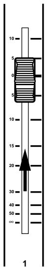
In addition to the DISPLAY ACCESS and SELECTED CHANNEL controls, each input channel and the stereo master channel utilizes a 100mm motorized fader. When a scene memory is recalled, the faders position themselves automatically to the levels stored. Fader movements are replayed automatically in synchronization with timecode automix during playback.
The faders allow you to quickly and accurately set the levels for the selected channels. By pressing the [FLIP] button, you can transfer fader control over your tape returns as well. Faders can be grouped into one of four fader groups for control of multiple faders from a single control. (There are also four mute groups which allow you to toggle a group of channels on or off.) You can also control two adjacent channels in stereo with the pair operation using only one fader.
Internal Stereo Effects
The 02R features eight aux sends, two of which are routed to the internal multi-effects stereo processors: Effect 1 and Effect 2. Using the power of Yamaha's proprietary effects processor chip, the 02R has a startling range of special effects available to apply to your mix. Shimmering revers, clean and precise delays, flanging and chorus, and a myriad of other effects are available built right into this mixer. The effects are processed entirely within the digital domain, ensuring the signal quality is the finest that a digital system can provide.
External effects processors can be patched into the system using the 02R's analog AUX send outputs, which feature 18-bit linear, 8-times oversampling D/A converters.
Effects can be applied to input channels or the tape return channels, and the auxiliary sends can be configured pre-fader or post-fader. There are 40 preset effects programs and 88 user effects programs for you to store your own settings.
Dynamics Processors
Dynamics processors are generally used to correct or control signal levels. However, you can also use them creatively to shape the volume envelope of a sound. The 02R features comprehensive dynamics processors for all the input, return, bus, and stereo output channels—a total of 50 processors. These processors allow you to compress, expand, limit, gate, or duck the signals passing through the mixer, giving you unparalleled sonic quality and flexibility.
Similar to the internal stereo effects, the dynamics processors are patched directly into the signal path while the audio data remains in the digital
domain. The dynamics program settings are stored in the dynamics library. There are 40 preset programs for you to recall and 88 user programs for you to store your own dynamics programs
Parametric EQ with Library
The 02R contains a high-performance four-band, fully parametric EQ. Each input channel, tape and effect return, and the stereo output channel features an EQ. You can tailor the EQ curve with a high degree of precision, covering the entire dynamic spectrum from 21Hz to 20.1kHz . Select the center-frequency (F) and adjust the bandwidth (Q) and the gain (G) until you have achieved the perfect sound.
EQ settings can be stored and recalled using scene memories, and can be adjusted in real-time with the dynamic automix system. The 02R also has an extensive EQ library which allows you to store frequently used EQ settings for instant recall. An EQ program stored in the EQ library is a good starting point and reference when making adjustments to the EQ.
Digital Benefits
You're probably already familiar with the many benefits of digital audio, but what exactly are the benefits for digital audio mixing?
An audio mixer has the job of combining audio signals from various sources, at differing levels and impedances, usually into a stereo signal. It must do this without introducing any new distortions and noise. Most analog mixers do a pretty good job, but even with the best designs, nonlinear effects caused by circuit components are unavoidable.
In the digital realm, audio mixing consists of adding and multiplying the binary numbers that represent audio signals. The 02R uses a 32-bit DSP (Digital Signal Processor) chip for these calculations, ensuring a very high degree of precision. Once past the analog-to-digital conversion, audio signals are essentially immune from standard signal degradation. With the 02R, noise, distortion, and crosstalk are virtually eliminated. You'll hear a new clarity in your mixes.
Once in the digital realm, there's little point converting back to analog. The 02R features stereo digital outputs for direct mixdown to DAT and other digital recorders. It uses the industry standards AES/EBU or IEC958 Part 2 (Consumer) for its digital inputs and outputs. With one of the optional digital I/O cards installed in your 02R, you can record direct-to-digital to your modular digital multitrack recorder.
02R Sonic Performance
The 02R uses linear 20-bit 64-times oversampling analog-to-digital converters to provide a typical dynamic range of 105dB . This means that an audio program's dynamic range, from low to high levels, is processed intact. The 02R samples audio at 44.1kHz or 48kHz . It provides a full spectrum frequency response from 20Hz to 20kHz , +1 , -3dB .
For digital-to-analog conversion, the 02R features 20-bit 8-times oversampling for its main stereo outputs, including the control room monitor outputs, and 18-bit 8-times oversampling for the studio and aux send outputs. Oversampling and bitstream techniques effectively increase the internal sampling rate, so side effects caused by steep low-pass filters, which are used to filter out undesirable sampling frequency components during conversion, are virtually eliminated. Consequently, audio signal integrity is maintained from input through to output.
2
Getting Started
In this chapter...
Basic Assumptions. 14
Making the Connections. 14
Basic Setup 15
Power ON/OFF. 16
Setting the Synchronization 16
Recall Scene Memory 0. 17
Basic Assumptions
The 02R was designed to be the perfect digital mixing console for a studio using the current generation of modular digital multitrack tape and disk recorders. Although the 02R can also be used as a sound-reinforcement mixer, the typical user will own a project recording or post-production studio with some form of multitrack recorder. Therefore, your 02R will probably be equipped with one or more of the optional input/output cards. For the purposes of these tutorials, it does not matter if you are working with an analog or digital multitrack.
What You Will Need
To perform the following tutorials, you will need:
The 02R.
- A sound source: CD player, drum machine, synthesizer/sequencer with demo song.
- Amplifiers and speakers, or headphones.
- A multitrack recorder and a stereo master recorder.
Audio connecting cables.
Making the Connections
WARNING! Before making any connections, make sure that all your equipment is turned OFF.
- Connect your sound source to input channel 1.
If you are using a stereo sound source, connect it to input channel 2 as well. A stereo source is not essential, and for most of the tutorials it will probably be easier to work with just one channel. If your sound source has XLR-type connectors, connect it to the XLR-type connectors on the 02R. Otherwise, use the phone jacks and select INPUT B with the [A/B] switch. - Connect the C-R MONITOR OUT connectors to the inputs on your power amplifier.
If you are using headphones, connect them to the PHONES jack.
- Connect your multitrack recorder to the appropriate optional input/output card.
WARNING! The 02R should be connected only an AC receptacle of the voltage type marked on rear panel.
You can also connect your stereo master recorder to either the digital or analog STEREO OUT connectors.
4. Plug the 02R into a suitable AC receptacle.
Basic Setup
The following illustration shows how to set up a minimal system that will allow you to perform the following tutorials.
Power ON/OFF
This section explains how to power the 02R on and off.
Power ON
It is always important to observe the correct order for powering up equipment in a studio. Always start with the multitrack and mastering recorders and the signal processors, then the 02R, and finally the monitoring amplifiers and other downstream gear.
POWER ON/DOFF
1. Turn ON the power to the 02R by pressing the POWER switch on the rear panel.
The 02R start-up screen appears for a few seconds, the faders return to their previous positions, then the page that was used when the 02R was last powered off appears.
Power OFF
It is always important to observe the correct order for powering off equipment in a studio. Always start with the monitoring amplifiers and other downstream gear, then the 02R, and finally the multitrack and mastering recorders and the signal processors.
1. Turn OFF the power to the 02R by pressing the POWER switch on the rear panel.
All mix settings, mix scenes, and other data are stored when the 02R is powered off.
Setting the Synchronization
Before you use the 02R with a modular digital multitrack recorder or DAT master recorder, be sure to correctly set the synchronization. The 02R must be slaved to an external wordclock in order to process the input digital signals without drop-out or distortion. Refer to the section "Word Clock Select" on page 188 of the User's Guide.
Look in the chapter "Installing Options" on page 217 of the User's Guide. There is a section for each of the optional digital I/O cards that the 02R supports. Refer to the appropriate section for the card installed in your 02R.
Recall Scene Memory 0
Before you start the tutorials, you should set the 02R to its initial mixer settings.
- Use the SCENE MEMORY increment or decrement buttons to select scene memory 0 "0 Initial Data".
- Press the (RECALL) button.
This is a read-only scene memory that contains the default settings for the system. The 02R will be reset to its initial settings.
Note: It is best to start at the beginning of each tutorial and work your way through, taking breaks as required. If you deviate too far from the tutorial, or jump into a tutorial halfway through, you may find that subsequent tutorial steps do not work as expected. Also note that the tutorials do not explain all 02R functions, nor do they serve as a substitute for the User's Guide explanations. For full details on all 02R functions, refer to the User's Guide.
3
Introductory Recording Tutorial
In this chapter...
Setting the Input Level 20
Applying EQ 24
Using the EQ Library 30
Routing 35
Panning 38
Setting the Input Level
Assuming that the 02R is powered ON and your music source is playing, the very first thing you need to do is set up a basic control room monitor mix. When you recall Scene Memory 0 "0 Initial Data", all the channel faders are set to the 0 dB mark.
Setting Fader Levels
If the faders are not set to 0dB , you should perform the following steps to optimize the input signal level for the best performance:
1. Set the fader for MIC/LINE 1 to the 0 dB mark.
The 0 dB fader position is a good place to start when setting fader levels. It is a good setting with regard to signal level and noise performance and it leaves room for you to raise the level later, if necessary.
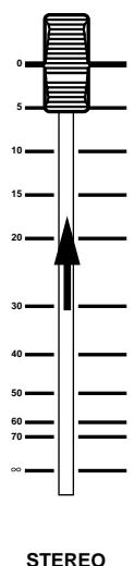
2. Set the STEREO fader to the 0 dB mark.
The stereo output meters are indicating the stereo output level. The stereo mix signal is now being output to the digital and analog STEREO OUT connectors.

Selecting a Monitor Source
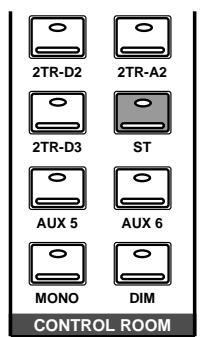
Before you can hear anything through your monitor amplifier and speakers, you have to select a Control Room source:
1. Press the (ST) button of the CONTROL ROOM buttons group.
This selects the stereo bus for monitoring in the control room.
2. Adjust the volume with the C-R LEVEL control.
You should be able to hear the sound source through your monitor speakers. If you are using stereo headphones, you will need to adjust the PHONES LEVEL control to set a comfortable listening level.
Note: Be very careful with the level settings, especially if you are using stereo headphones. When you are adjusting a unit as complex as the 02R, it is possible for you to inadvertently switch on a very loud signal source. Damaged loudspeakers or amplifiers can be very expensive. Damage to your hearing can be much worse. Your ears are for life!
Setting the GAIN

- Use the (METER) button to locate the METER 1/3 page.
The MIC/LINE 1 signal is metered.
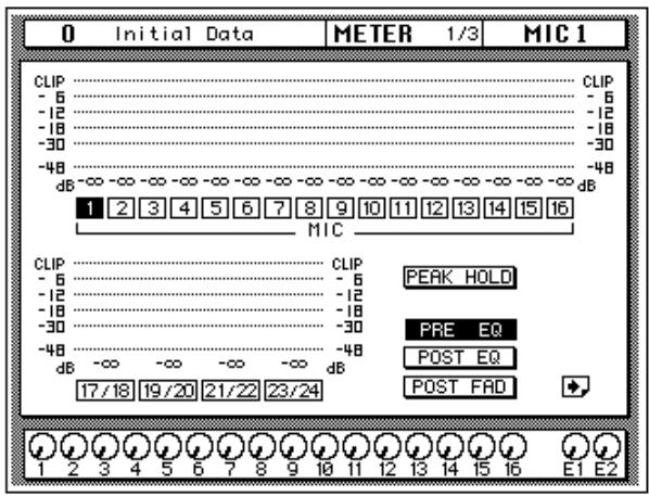

- If the sound is distorted, the PEAK indicator is illuminated, or the level is going up to CLIP, press the 20 dB (pad) switch to attenuate the input signal for MIC/LINE 1.
You usually need to pad (attenuate) the input signal when you connect a line level device, such as a synthesizer or an effects unit to the channel. If you connect a microphone, you should not need to pad the signal.
If you want to use a high impedance device, such as a guitar or bass guitar, you should insert a direct box or effects processor between the guitar and the 02R—or you should mike the guitar amplifier.
Note: The stereo input channels (LINE 17 through 24) accept line level signals only.
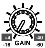
- Use the GAIN control for MIC/LINE 1 to optimize the signal level.
Ideally the level should be set relatively high to obtain the best signal-to-noise performance. It is acceptable for the PEAK indicator to occasionally illuminate but the signal levels should not reach CLIP. If the PEAK indicator illuminates constantly, the signal is overloading the input preamplifier and you may be able to hear analog clipping distortion. When CLIP is reached, you will experience digital clipping distortion, which is usually very unpleasant sounding.
Back off the GAIN control a little until the PEAK indicator illuminates very occasionally. The GAIN control should be set with some care. If it is set too low, the signal-to-noise performance will suffer, and if it is set too high, signal clipping and distortion may occur.
/ ATT Display Function
If a lot of EQ boost is applied, the signal level may reach CLIP on the METER page but the PEAK LED may not light up. Instead of lowering the GAIN control, which would reduce A/D converter efficiency, you can use the Attenuator function to attenuate the level.

1. Press the (Ø/ATT) button.
The /ATT 1/1 page shown below appears.
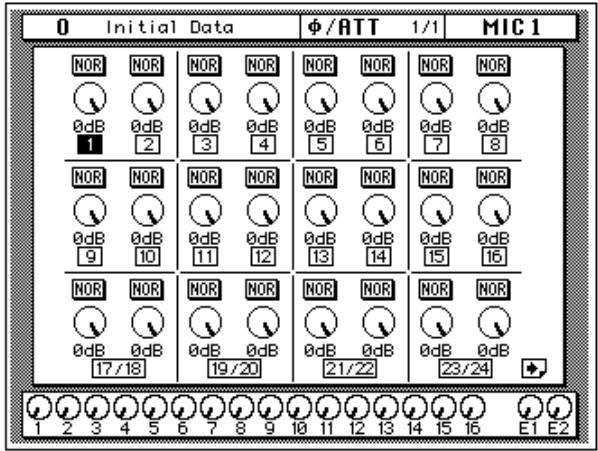

2. Press the (SEL) button for MIC/LINE 1.
3. Use the encoder wheel to attenuate the signal.
On the / ATT page you can attenuate signals and reverse the phase, all in the digital domain.
Note: You should rarely find it necessary to use the / ATT function on an input signal after the gain level has been correctly set, but you may need to attenuate after you apply EQ, effects, or dynamics to the signal.
Peak Hold

- Use the (METER) button to locate the METER 1/3 page.
- You may find the Peak Hold function useful at this point. To turn it on, use the CURSOR buttons to select the PEAK HOLD icon and press (ENTER). When the Peak Hold function is on, its icon is highlighted.
The peak level is indicated by an empty square box. Peak Hold is very useful for level checking before recording. You can leave a mix to play through unattended while Peak Hold watches out for signal peaks. If any levels reach CLIP, back off the relevant GAIN control or use the /ATT display function to attenuate the signal and run through the mix again.
Note: The Peak Hold function also works on the stereo output meters and controls the optional meter bridge (MB02).
3. To clear the Peak Hold levels, select the PEAK HOLD icon with the CURSOR buttons and press (ENTER).
When you clear the Peak Hold levels, it also clears the peaks from the stereo output meters.
Typically, you will be using more than just one input channel, so you will need to set the input signal level for each channel individually. Since it is relatively easy to set them at this point, take time and care. If you have to adjust them later in the mixing process, you may need to adjust the faders, auxiliary sends, and other levels, as well.
Channel ON/OFF
The channel [ON] buttons are used to turn channels ON or OFF. This function is sometimes called MUTE. When you recall Scene Memory 0 "0 Initial Data", all the channels are turned ON.

1. Press the channel (ON) button for MIC/LINE 1.
The sound is cut and the LED inset in the [ON] button switches off.
Note: Even though you can no longer hear the sound source, the meter for MIC/LINE 1 continues to be displayed. This is because the meter signal is sourced before the [ON] button.
2. Press the (ON) button again to turn the channel back ON.
The LED inset in the [ON] button illuminates again and you will be able to hear the sound source again.
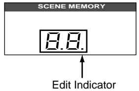
SCENE MEMORY LED
The 2-digit (7-segment) LED shows the currently selected scene memory. It also contains the Edit Indicator, which will start flashing when you adjust the first digital parameter of the current scene memory. See "Scene Memories" on page 62 of the Getting Started Guide.
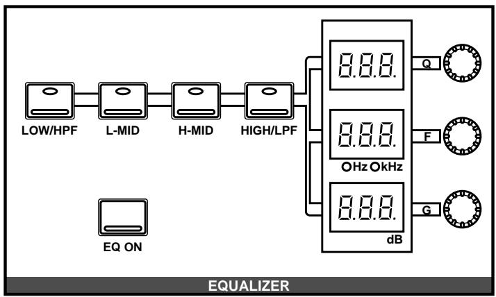
Applying EQ
The next step is to apply EQ to MIC/LINE 1.
Each 02R channel features a four-band fully parametric EQ, with variable bandwidth (Q), frequency (F), and gain (G). The power of the 02R user interface means that there are two ways of adjusting the EQ for MIC/LINE 1.
One method is to use the EQ 1/2 page.
The more convenient method is to use the buttons and controls of the EQUALIZER block of the SELECTED CHANNEL controls.
Note: You can customize your 02R so that when you adjust a control of the EQ block of the SELECTED CHANNEL controls, the EQ 1/2 page automatically appears. See "Preferences" on page 198 of the User's Guide for more information. The default setting is to automatically display the EQ page.
The rest of this tutorial describes the operation of the EQ 1/2 page.
Turning the EQ ON/OFF

1. Press the (SEL) button for MIC/LINE 1.
When you press the [SEL] button for a channel, the LED and numeric indicators of the SELECTED CHANNEL controls change to reflect the status of the channel you selected.

2. Press the (EQ) button.
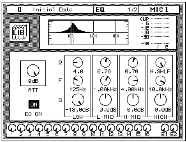
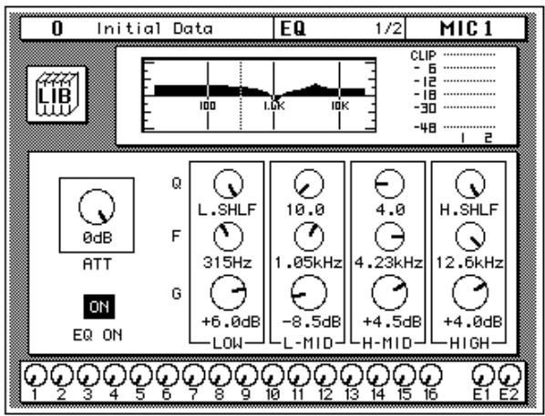
The EQ 1/2 page appears, showing the EQ curve and settings for MIC/LINE 1.

3. Use the CURSOR buttons to select the EQ ON icon.
If the EQ is ON, the icon will be highlighted. The LED inset in the [EQ ON] button of the SELECTED CHANNEL—EQUALIZER block controls will also be illuminated.
4. To turn the EQ either on or off, press the (ENTER) button or the (EQ ON) button.
The ON icon will change to OFF. The LED inset in the [EQ ON] button will no longer be illuminated.
Turn the EQ on for the remainder of this tutorial.
Setting the Gain
- Select the gain (G) icon for the LOW band using the CURSOR buttons.
Alternatively, press the [LOW/HPF] button of the SELECTED CHANNEL—EQUALIZER controls.
- Rotate the encoder wheel clockwise to boost the gain.
Alternatively, you could use the EQUALIZER G control.
The gain increases in 0.5 dB steps and the EQ curve on the EQ page changes to reflect this.

3. Rotate the encoder wheel counterclockwise to reduce the gain.
The gain decreases in 0.5 dB steps.
Alternatively, you could use the EQUALIZER G control.
4. Use the CURSOR buttons to select the gain (G) icon for the L-MID band and adjust its level with the encoder wheel. Select the other bands as well.
You can also select the EQ bands using the [LOW/HPF], [L-MID], [H-MID], and [HIGH/LPF] buttons of the SELECTED CHANNEL-EQUALIZER controls.
Note: Applying a lot of EQ boost may increase the signal level sufficiently to cause distortion. If this does occur, reduce the amount of EQ boost or adjust the attenuation level to compensate (the ATT icon). You can switch back to the METER 1/3 page and select POST EQ to monitor the signal levels.
Note: You can reset the gain of each band to 0.0 dB by double-clicking the corresponding [LOW/HPF], [L-MID], [H-MID], or [HIGH/LPF] buttons of the SELECTED CHANNEL-EQUALIZER controls.
Setting the Frequency
- Select the frequency (F) icon for the LOW band using the CURSOR buttons.
- Use the encoder wheel to sweep through the frequency range.

Alternatively, you could use the EQUALIZER F control.
All four bands of the 02R parametric EQ cover virtually the entire audio spectrum, from 21Hz to 20.1kHz . Although they are labelled LOW, L-MID, H-MID, and HIGH, the frequency of the bands can actually be in any order.
Note: If your 02R is busy processing some complex data, it may take a little time to update the EQ curve. However, the internal EQ circuits reflect your adjustments immediately.
Note: As well as the frequency value in Hz displayed under the icon and on the numeric LED in the SELECTED CHANNEL—EQUALIZER controls, the dotted vertical line on the EQ graph indicates the current frequency position.
- Use the CURSOR buttons to select the frequency (F) icon for the L-MID band and adjust its position with the encoder wheel. Select the other bands and adjust their frequency.
You can also select the EQ bands using the [LOW/HPF], [L-MID], [H-MID], and [HIGH/LPF] buttons of the SELECTED CHANNEL-EQUALIZER controls. Adjust the EQUALIZER F control for each band.
Setting the Bandwidth
The L-MID and H-MID bands are peaking type EQs. The LOW and HIGH bands are initially configured as shelving type EQs, however, they can also be configured as peaking type EQs. The LOW band can also be configured as a HPF (high-pass filter) and the HIGH band as a LPF (low-pass filter).
- Select the bandwidth (Q) icon for the LOW band using the CURSOR buttons.
- Use the encoder wheel to sweep through the bandwidth.
Alternatively, you could use the EQUALIZER Q control.
The LOW band changes from low-shelving to peaking to high-pass filter as you continue to rotate the encoder wheel.
- As you rotate the encoder wheel counterclockwise, it effectively increases the Q—narrowing the bandwidth, as shown on the EQ graph.
A narrow curve is useful for boosting or cutting specific frequencies.
- Use the CURSOR buttons to select the bandwidth (Q) icon for the L-MID band and adjust its position with the encoder wheel. Select and adjust the bandwidth of the other bands.
You can also select the different bands using the [LOW/HPF], [L-MID], [H-MID], and [HIGH/LPF] buttons of the SELECTED CHANNEL-EQUALIZER controls. Adjust the EQUALIZER Q control for each band.
The HIGH band changes from high-shelving to peaking to low-pass filter as you adjust its value.
Resetting the EQ
- Press and hold the (LOW/HPF) button and then press the (HIGH/LPF) button of the SELECTED CHANNEL—EQUALIZER controls.
All EQ values will be reset to their initial values.
| LOW/HPF | L-MID | H-MID | HIGH/LPF | |
| Q | LOW SHELF | Peak - 0.7 | Peak - 0.7 | HIGH SHELF |
| F | 125 Hz | 1.00 kHz | 4.00 kHz | 10.0 kHz |
| G | 0 dB | 0 dB | 0 dB | 0 dB |
Using the EQ Library
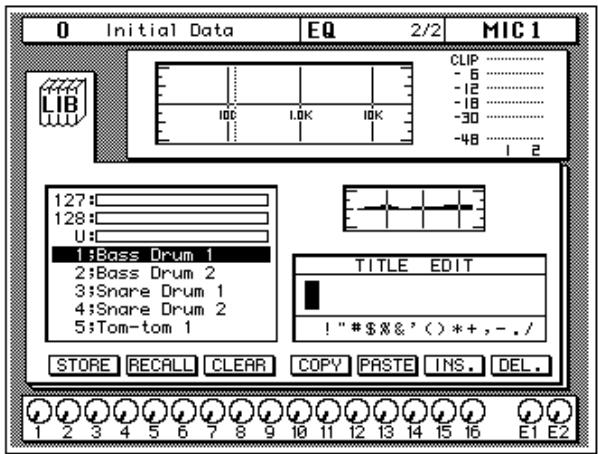
The EQ Library is used to access and store EQ settings—stored as programs. There are 32 preset programs (1 to 32) for you to recall and 96 user programs (33 to 128 plus UNDO) for you to store your own EQ settings. First you need to know how to recall EQ programs, then how to store your own.
Note: The programs 33 to 40 contain preset programs and are listed in the "EQ Programs" on page 54 of the User's Guide. However, you can store your own settings to these programs.
Recalling an EQ Program
- Use the (EQ) button to locate the EQ 2/2 page shown below.


The top of the page shows the EQ curve for the selected channel and a level meter for the channel and its adjacent pair.
- Press the (SEL) button for MIC/LINE 1.
This step is required only if you have selected another channel.
- Select the RECALL icon with the CURSOR buttons.
In order to scroll through the list of EQ programs, the cursor must be on the STORE, RECALL, CLEAR, COPY, or PASTE icons.
- Use the encoder wheel to select an EQ program.
As you scroll through the EQ programs, the EQ curve for each program is displayed to the left of the list.
- Press the (ENTER) button.
The EQ program is recalled. The EQ curve for MIC/LINE 1 is set accordingly. The EQ curve at the top of the display is updated.
Your sound source is modified by the program you recalled. If the sound doesn't change, check if you have left the EQ ON switch turned OFF on the EQ 1/2 page. You can also quickly check if the LED inset in the EQ ON button of the SELECTED CHANNEL—EQUALIZER controls is illuminated or not.
6. Use the (EQ) button to locate the EQ 1/2 page.
The EQ 1/2 page shows the updated EQ curve and exact settings of the EQ program recalled.
Undoing a Recall
You can undo EQ program recalls by recalling the "U" EQ program, which contains the previous EQ settings.
-
Use the CURSOR buttons to select the RECALL icon and rotate the encoder wheel until program "U" is highlighted.
-
Press the (ENTER) button.
The previous EQ settings are recalled.

Storing an EQ Program
- Use the (EQ) button to locate the EQ 2/2 page shown below.
- Select the STORE icon with the CURSOR buttons.
In order to scroll through the list of EQ programs, the cursor must be on the STORE, RECALL, CLEAR, COPY, or PASTE icons.
- Use the encoder wheel to select an EQ program.
If you select one of the preset programs (1 to 32), an error message appears when you attempt to store your program. Select a program from the 96 user programs (33 to 128). You cannot store your settings to the "U" program either.
- Use the CURSOR buttons to select the TITLE EDIT box.

5. Select the individual character positions with the CURSOR buttons and rotate the encoder wheel to select the characters.
You can create a name of up to 16 characters long. It can contain any of the following characters:
| ! | “ | # | $ | % | & | ' | ( | ) | * | + | , | - | . | / | |
| 0 | 1 | 2 | 3 | 4 | 5 | 6 | 7 | 8 | 9 | : | ; | < | = | > | ? |
| @ | A | B | C | D | E | F | G | H | I | J | K | L | M | N | O |
| P | Q | R | S | T | U | V | W | X | Y | Z | [ | \ | ] | ^ | _ |
| ` | a | b | c | d | e | f | g | h | i | j | k | l | m | n | o |
| p | q | r | s | t | u | v | w | x | y | z | { | | | } | ~ |
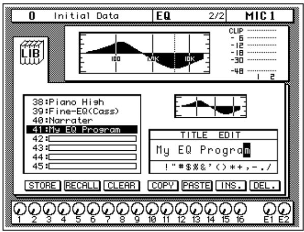
You can select the "INS." icon to insert a space (blank) at the current cursor position. Select the icon with the CURSOR buttons and press the [ENTER] button. The "DEL." icon is used to delete the character at the cursor position.
Note: The "COPY" and "PASTE" icons allow you to select the title from another EQ program and paste it into your program. These icons only copy the title, not the actual EQ settings. See "Icons" on page 55 of the User's Guide.
6. Use the CURSOR buttons to select the STORE icon and press the (ENTER) button.
The 02R displays a confirmation dialog box asking if you want to store your settings in the selected EQ program. The dialog box has two icons: "CANCEL" and "EXECUTE".
Note: You can customize your 02R to prevent the dialog box appearing during STORE operations. In this case, the program is stored without confirmation. See "Preferences" on page 198 of the User's Guide for more information.
CANCEL is the default. To cancel the STORE operation, either press the [ENTER] button or wait about 10 seconds—the STORE operation will be automatically cancelled.
To store your settings, use the CURSOR buttons to select the "EXECUTE" icon and press the [ENTER] button. The EQ program is stored.
Note: If you decide you don't like an EQ program after you have stored it, it is very easy to overwrite it by creating new settings and storing them to the same location. Conversely, it is also very easy to accidentally overwrite a valued EQ program.
YOU SHOULD ALWAYS BE CAREFUL WHEN THE 02R DISPLAYS A CONFIRMATION Dialog Box!
Routing
This tutorial assumes you have a multitrack recorder and you have connected it to your 02R—after having one or more of the optional input/output cards installed:
- Alesis ADAT (CD8-AT)—This single slot card supports an 8-channel ADAT compatible modular digital multitrack recorder. It provides eight input channels and eight output channels. You can insert up to four of these cards in the 02R.
- TASCAM TDIF-1 (CD8-TDII)—This single slot card supports an 8-channel TASCAM modular digital multitrack recorder. It provides eight input channels and eight output channels. You can insert up to four of these cards in the 02R.
- YAMAHA (CD8-Y)—This single slot card supports an 8-channel YAMAHA modular digital multitrack recorder. It provides eight input channels and eight output channels. You can insert up to four of these cards in the 02R.
- AES/EBU (CD8-AE double slot card, CD8-AE-S single slot card)—These cards support an 8-channel AES/EBU compatible modular digital multitrack recorder (such as the Akai DD1500 series). They provide eight input channels and eight output channels.
- Analog AD/DA (CD8-AD)—This double slot card supports any 8-channel analog multitrack recorder. It provides eight input channels and eight output channels. You can insert only two of these cards in the 02R.
The 02R allows you to route the first 16 MIC/LINE channels directly to an output. If you have the correct configuration, this means you can send direct outputs to a 16-track recorder (for example, two paired ADAT compatible modular digital multitrack recorders).
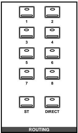
You can route any channel to one of the eight output buses. The buses feed to each of the four 8-track I/O slots in the back of the 02R. You can also route any channel to the stereo bus.
When you recall Scene Memory 0 "0 Initial Data", all the channels are routed to the stereo bus.
Using the ROUTING Display Function
There are two ways to operate the Routing function.
One method is to use the ROUTING 1/2 page.
The more convenient method is to use the buttons of the ROUTING block of the SELECTED CHANNEL controls.
Note: You can customize the 02R so that when you press a button in the ROUTING block of the SELECTED CHANNEL controls, the ROUTING 1/2 page automatically appears. See "Preferences" on page 198 of the User's Guide for more information.
Selecting the Routing

- Use the (ROUTING) button to locate the ROUTING 1/2 page shown below.
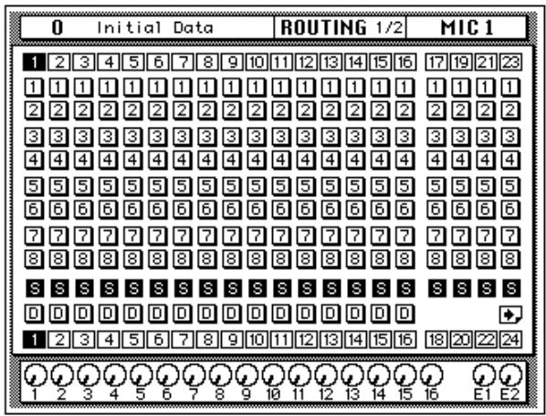
2. Use the ROUTING buttons of the SELECTED CHANNEL controls to route the MIC/LINE 1 channel.
As you press the ROUTING buttons, the LED inset in the button illuminates and the corresponding icon on the ROUTING page appears highlighted.
You can also operate the routing using the CURSOR buttons to move to the desired routing icon and pressing the [ENTER] button.
Note: When you select a route, the signal from the channel will be routed to the selected bus. The output from that bus will appear at the corresponding outputs of all the I/O cards installed in the 02R. The only exception is when you are using I/O cards in slots 1 and 2 for direct output. See "Routing" on page 39 of the User's Guide for further details.
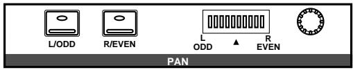
Panning
There are two ways to use the Pan function.
One method is to use the PAN 1/1 page.
The more convenient method is to use the buttons and controls of the PAN block of the SELECTED CHANNEL controls.
Note: You can customize your 02R so that when you adjust a control of the PAN block of the SELECTED CHANNEL controls, the PAN 1/1 page automatically appears. See "Preferences" on page 198 of the User's Guide for more information.
Adjusting the Pan
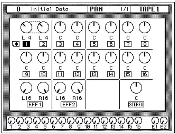
1. Press the (PAN) button.
The PAN 1/1 page shown below appears.
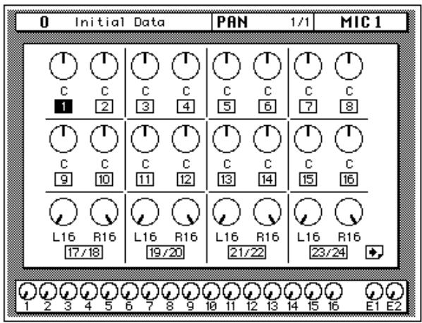
2. Press the (SEL) button for MIC/LINE 1 and rotate the PAN control.
The LED inset in the [L/ODD] button will be illuminated. The current pan position is indicated on the adjacent LED bargraph. As an alternative, you can use the CURSOR buttons to select the PAN icon for MIC/LINE 1 and rotate the encoder wheel.
You can adjust the pan position from extreme right/even (R16) through the center (C) to extreme left/odd (L16). There are 33 pan positions to choose from.
Ganging Pans
You can gang the pan controls of two adjacent channels for simultaneous pan adjustment
1. Press the (SEL) button for MIC/LINE 1.
You can also select the MIC/LINE 1 icon using the CURSOR buttons.
2. Press the (ENTER) button to connect the channels together.
You can also gang channels together by simultaneously pressing the [L/ODD] and [R/EVEN] buttons of the PAN block of the SELECTED CHANNEL group.
Ganged pan is indicated by a pair of dotted lines between the pan controls, as shown below.
When you adjust one channel, the ganged channel also moves by a corresponding amount. For further details, see "Pan Gang" on page 37 of the User's Guide.
4
Secondary Recording Tutorial
In this chapter...
AuxSends. 42
Setting the Aux Send Level 43
Creating a Monitor Mix 45
Applying Effects 46
Recalling and Editing Effects 49
Patching in a Dynamics Processor 54
Using the Dynamics Library 57
Scene Memories 62
Aux Sends
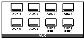
The 02R has eight aux sends.
AUX 7 and AUX 8 are used to feed the internal effects processors, with the signal remaining entirely in the digital domain.
The other auxiliary sends—AUX 1 through AUX 6—can be used to feed external signal processors and effects units, foldback amplifiers, or multitrack recording equipment. AUX 5 and AUX 6 can also be used to construct a monitor mix, and routed directly to either the studio or control room monitors. When a send is used to feed an external effects processor, the processed signal can be returned via one of the stereo input channels or an unused input channel.
There are two different ways to access the auxiliary send channels:
DISPLAY ACCESS—AUX buttons
- The [AUX 1] to [AUX 6] buttons access the AUX 1 to 6 pages, which display the aux send level controls and pre/post icons.
- The [AUX 7] and [AUX 8] buttons access the AUX 7 and 8 pages, which are used with the internal effects processors: Effect 1 and Effect 2.
When an AUX button is pressed, the faders and rotary encoders control aux send levels, not channel levels.
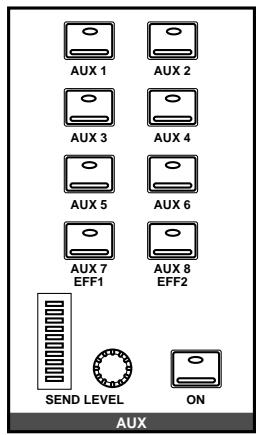
SELECTED CHANNEL—AUX controls
These buttons and controls set the aux send levels for the selected channel.
- The [AUX 1] to [AUX 8] buttons allow you to select the aux buses you want to send the selected channel signal to.
- The SEND LEVEL rotary encoder is used to set the level—indicated by the adjacent LED bargraph.
- The [ON] button is used to turn the send on or off.
Setting the Aux Send Level
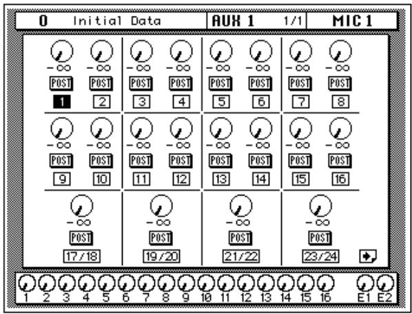
In this tutorial, MIC/LINE 1 channel is sent to AUX 1.

AUX 1
1. Press the (AUX 1) button.
The AUX 1 1/1 page shown below appears.
| FADER STATUS |
| 0 INPUT |
| ∇ AUX |
| 1 2 3 4 |
| 5 6 7 8 |
The faders change from channel level controls to aux send level controls. To indicate the change, the AUX LED of the FADER STATUS indicator illuminates. The number indicator corresponding to the current AUX button (in this case, AUX 1) is also illuminated. The faders automatically move from their channel level positions to the aux send level positions.
Note: Avoid blocking the fader movements when the faders move to their aux send positions by placing objects on the 02R. It is possible to damage the faders.
Although the faders have moved to the auxiliary send level positions, the 02R remembers the channel signal levels.
2. Select MIC/LINE 1 using the (SEL) buttons or the CURSOR buttons.
Turn the aux send on by pressing the [AUX 1] button and then the [ON] button in the AUX group of the SELECTED CHANNEL controls. The default is for the send to be ON, therefore this step is not usually required.
Note: In order to change the aux send status from on to off, you must first select the send channel with the corresponding button of the SELECTED CHANNEL—AUX controls
3. To change the aux send from post to pre fader, press the (ENTER) button.
The PRE icon becomes the POST icon and is highlighted when the signal is pre-fader.

4. To change the signal level, adjust the fader for MIC/LINE 1 until the desired value is obtained.
You can use the rotary encoders for the tape returns or press the [FLIP] button. Then the tape return channels can be operated by the faders. The effect returns can only be adjusted with the rotary encoders.
You can also use the SEND LEVEL encoder in the AUX group of the SELECTED CHANNEL controls. You must press the corresponding [AUX 1] button to make certain you are adjusting the signal level for the correct aux send.
Note: In order to adjust the aux send level with the SEND LEVEL encoder, you must first select the send channel with the corresponding button of the SELECTED CHANNEL—AUX controls
Creating a Monitor Mix
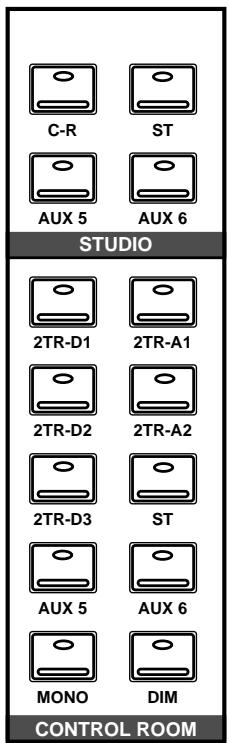
The 02R has two different monitoring outputs—the control room outputs and the studio outputs—plus, of course, the PHONES output (which is a duplicate of the control room output).
During a multitrack recording session, what you want to listen to in the control room is often very different from what the musicians need in the studio. For example, while recording a rhythm section, the bass player and the drummer may want to hear the kick drum at a much higher volume than you need in the control room.
To cater to this requirement, the 02R allows you to create a mono monitor mix using either AUX 5 or AUX 6 or a stereo mix using both AUX 5 and AUX 6.
Monitor Mix Process
The process for creating the monitor mix is similar to the steps detailed in "Setting the Aux Send Level" on page 43 of the Getting Started Guide
- Press the (AUX 5) button.
- Select MIC/LINE 1 using the (SEL) buttons or the CURSOR buttons.
Turn the aux send on by pressing the [AUX 5] button and then the [ON] button in the AUX group of the SELECTED CHANNEL controls.
You should leave the send pre-fader. This will allow the musicians to continue to hear each other independently of anything you may be doing in the control room.
- Press the (AUX 5) button of the STUDIO buttons group.
You should also press the [AUX 5] button of the CONTROL ROOM buttons group so you can hear the results of adjusting the levels.
- Adjust the fader for MIC/LINE 1 until the desired signal level is obtained.
Use the Talkback system to check with your musicians, to see if they are content with the signal levels you have set. When you finish setting the studio monitor levels, press the [ST] button of the CONTROL ROOM buttons group for monitoring in the control room.
Applying Effects
The 02R features two internal multi-effects stereo processors: Effect 1 and Effect 2. These are fed by AUX 7 and AUX 8, and the processed signals are returned via EFF 1 RTN and EFF 2 RTN, respectively. When you use the internal effects, the signal gets processed without ever leaving the digital domain.
Effects can be applied to input channels or the tape return channels. Effects are organized into programs. There are 40 preset effects programs (1 through 40) and 88 user effects programs (41 through 128 plus an UNDO buffer) for you to store your own settings.
Setting the Send Levels
The process for applying effects is similar to the steps as detailed in "Setting the Aux Send Level" on page 43 of the Getting Started Guide. The following example shows applying effects to MIC/LINE 1 using AUX 7.

AUX 7 EFF1
- Use the (AUX 7) button to locate the AUX 7 1/3 page shown below.
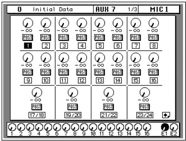
The faders automatically move from the channel level positions to the aux send level positions. Even though the fader has changed positions, the 02R remembers the channel signal levels.
Note: Avoid blocking the fader movements when the faders move to their aux send positions by placing objects on the 02R. It is possible to damage the faders.
- Select MIC/LINE 1 using the (SEL) buttons or the CURSOR buttons.
Turn the aux send on by pressing the [AUX 7] button and then the [ON] button in the AUX group of the SELECTED CHANNEL controls.
- Press the (ENTER) button to change the aux send from pre to post fader.
Sends to the effects are usually post fader. This means the signal level feed into the effects processor follows the "dry" channel level.
4. Adjust the fader for MIC/LINE 1 until the desired signal level is obtained.
Adjusting the Effect Return
The effect return channel is similar to one of the input channels except that it has no analog input, and therefore no gain or input pad need to be applied. Otherwise the steps are similar to those starting with "Setting the GAIN" on page 21 of the Getting Started Guide.
The easiest way of applying all the required adjustments is to select the View 1/2 page. This allows you to see all the parameters of the channel on one page, while you can still use the dedicated buttons and controls of the SELECTED CHANNEL group.

- Use the (VIEW) button to locate the VIEW 1/2 page shown below, and press the (SEL) button for EFF 1 RTN.
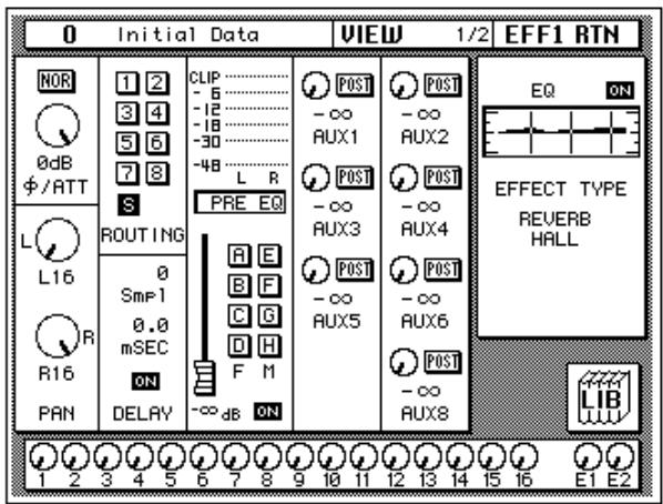
- If the sound is distorted or the level is constantly going up to CLIP, use the CURSOR buttons to select the /ATT icon. Adjust the level with the encoder wheel.
Note: In many cases, clipping in the effect return channel is caused by the send level being too high. You may need to adjust the send levels as well as the attenuation if you experience clipping.
- Select the PAN icon with the CURSOR buttons and set the pan position using the encoder wheel.
Note: Setting the pan position, routing, and EQ can all be done quickly and easily with the dedicated controls of the SELECTED CHANNEL block.
- Use the CURSOR buttons to select the ROUTING icons. Press the (ENTER) button to select routes for the effect return signal.
By default (assuming you are still working with Scene Memory 0 "0 Initial Data") the effect return channel is routed to the stereo bus.
Note: Although you cannot route the effect return channel to the direct outputs, you can route it to the same bus that the input channel is routed to, allowing you to record the effect together with the input signal.
Many engineers prefer to add effects only during the final mix. It is very easy to apply effects, but difficult to remove it once it has been recorded. You may want to send the effect to the monitor mix, however, especially when recording a vocalist—many vocalists dislike hearing their voice "dry" in the monitors.
5. Select the EQ graph with the CURSOR buttons and press the (ENTER) button.
The 02R will automatically switch to the EQ 1/2 page. Follow the steps detailed in "Applying EQ" on page 24 of the Getting Started Guide to set the EQ for the effect return channel EFF 1 RTN.
Note: Many engineers prefer to hold off applying EQ to a recording until they are ready to mixdown. Again, it is much easier to apply EQ than to subsequently remove it.
Recalling and Editing Effects
Once you have applied effects to MIC/LINE 1, you need to know how to recall effects programs from the effects library and to adjust their parameters in order to create your own effect programs.
Recalling Effects Programs

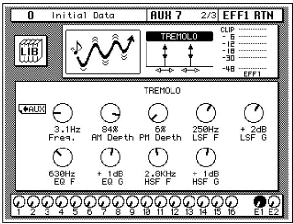
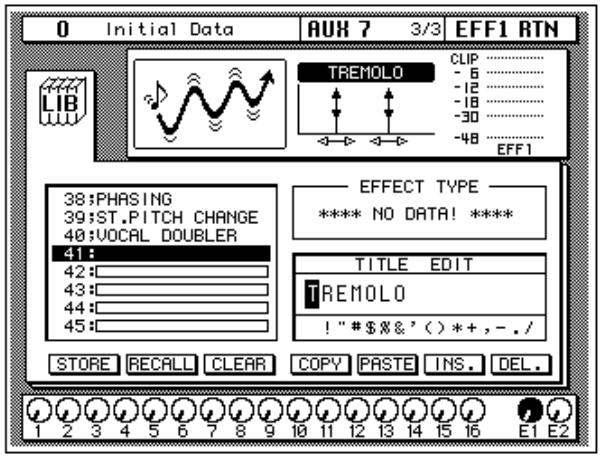
- Use the (AUX 7) button to locate the AUX 7 2/3 page shown below.

The parameters of the currently selected effects program are displayed on this page. You will see the library (LIB) icon, an effects curve or icon (depending on the selected effect), and a level meter for the effects return stereo pair, as well as icons for adjusting the parameters.
- Use the (AUX 7) button to locate the AUX 7 3/3 page shown below.
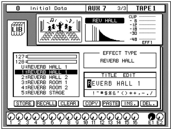
Alternatively, you could select the LIB icon and press the [ENTER] button to go to the AUX 7 3/3 page.
3. Use the CURSOR buttons to select the RECALL icon. Rotate the encoder wheel to select an effects program.
The 02R will scroll through the available effects programs. The program that is highlighted is the program that will be recalled when you press the [ENTER] button.
4. Press the (ENTER) button.
The effects program is recalled.
If you attempt to recall a user program that is empty, the 02R displays an error message, indicating that the selected memory location is not available for recall.
Editing Effects
You can edit the preset effects programs and then store them as user effects programs. The 02R has 40 preset programs (1 through 40). Some are simple variations of a basic effect, for example, different types of reverb and delay (echo) are available.
Select the preset effects program that is closest to the effect you are trying to achieve and edit its parameters.
1. Use the CURSOR buttons to select the LIB icon and press the (ENTER) button.
The AUX 7 2/3 page appears.
You can also press the [AUX 7] button to get to this page. This button allows you to access the aux send levels, the effects editing, and the effects library pages.
2. Select the various parameters with the CURSOR buttons, and adjust the value with the encoder wheel.
As you adjust the parameters, you should listen carefully to the results. Some of the parameters of some of the effects are very subtle in their effect, others are quite obvious.
After you have modified the effects program to your satisfaction, you are ready to store it.
Storing a User Effect
The 02R has 88 user effects program locations (41 through 128) for you to store your own settings. You can store your effects program in the Effect Library, or you can just rely on the 02R scene memory to recall your settings. The following instructions show you how to store your program in the library.
1. Select the LIB icon with the CURSOR buttons and press the (ENTER) button.
The AUX 7 3/3 page appears.
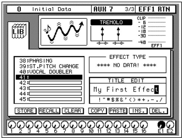
- Use the CURSOR buttons to select the TITLE EDIT box, as shown below.
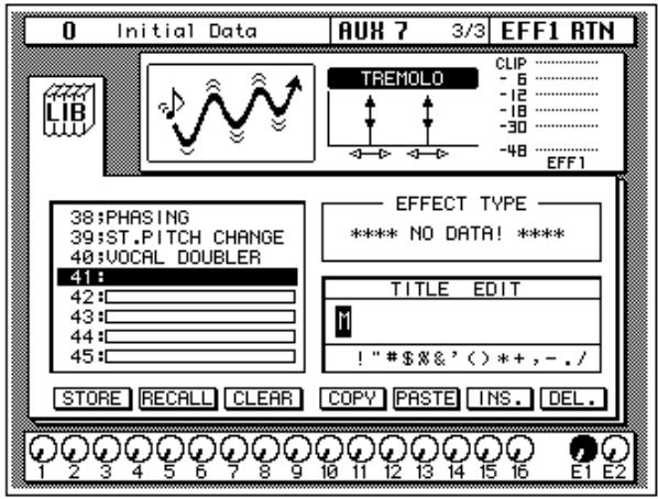
- Select the individual character positions with the CURSOR buttons. Use the encoder wheel to select the characters.
You can create a name of up to 16 characters long. It can contain any of the following characters:
| ! | “ | # | $ | % | & | ' | ( | ) | * | + | , | - | . | / | |
| 0 | 1 | 2 | 3 | 4 | 5 | 6 | 7 | 8 | 9 | : | ; | < | = | > | ? |
| @ | A | B | C | D | E | F | G | H | I | J | K | L | M | N | O |
| P | Q | R | S | T | U | V | W | X | Y | Z | [ | \ | ] | ^ | _ |
| ` | a | b | c | d | e | f | g | h | i | j | k | I | m | n | o |
| p | q | r | s | t | u | v | w | x | y | z | { | | | } | ~ |
You can select the "INS." icon to insert a space (blank) at the cursor position in the TITLE EDIT box. Select the icon with the CURSOR buttons and press the [ENTER] button. The "DEL." icon is used to delete the character at the cursor position.
Note: The "COPY" and "PASTE" icons allow you to select the title from another effects program and paste it into your program for subsequent editing. These icons only copy the title, not the effects settings. See "Icons" on page 110 of the User's Guide.
4. Use the CURSOR buttons to select the STORE icon. Rotate the encoder wheel to select an effects program.
If you select one of the preset programs (1 to 40), the message "Preset is read only!" appears when you attempt to store your program. Select a program from the 88 user programs (41 to 128).
You cannot store your settings to program "U" (the UNDO buffer) either.
5. Press the (ENTER) button.
The 02R displays a confirmation dialog box asking if you want to store your settings in the selected effects program. The dialog box has two icons: "CANCEL" and "EXECUTE".
Note: You can customize your 02R to prevent the dialog box appearing during STORE operations. See "Preferences" on page 198 of the User's Guide for more information.
CANCEL is the default. To cancel the STORE operation, either press the [ENTER] button or wait about 10 seconds—the STORE operation will be automatically cancelled.
To store your settings, use the CURSOR buttons to select the "EXECUTE" icon and press the [ENTER] button. The effects program is stored.
Note: If you decide you do not like an effects program after you have stored it, it is very easy to overwrite it by creating new settings and storing them to the same location. Conversely, it is also very easy to accidentally overwrite a valued effects program.
YOU SHOULD ALWAYS BE CAREFUL WHEN THE 02R DISPLAYS A CONFIRMATION_DIALOG BOX!
Patching in a Dynamics Processor
The 02R features comprehensive dynamics processors for all the channel inputs, tape returns, and stereo and bus outputs. These processors allow you to compress, expand, compress/expand (compand), gate, or duck the signals passing through the mixer.
The dynamics processors are generally used to correct or control signal levels, giving you unparalleled sonic quality and flexibility. You can also use them creatively to shape the volume envelope of a sound.
Compressor
A compressor provides a form of automatic level control. It attenuates high levels, thus effectively reducing the dynamic range, making it much easier to control signals and set appropriate fader levels. Reducing the dynamic range also means that recording levels can be set higher, thereby improving the signal-to-noise performance.
Limiting is an extreme form of compression, where the output signal is sharply attenuated so that it cannot exceed a particular level.
Expander
An expander is another form of automatic level control. By attenuating the signal below the threshold, the expander reduces low-level noise or expands the dynamic range of the recorded material.
Compander
A compander is a compressor/expander—a combination of signal compression and expansion. The compander attenuates the input signal above the threshold as well as the level below the width. For very dynamic material, this program allows you to retain the dynamic range without having to be concerned with excessive output signal levels and clipping.
Gate and Ducking
A gate, or noise gate is an audio switch used to mute signals below a set threshold level. It can be used to suppress background noise and hiss from valve (tube) amps, effects pedals, and microphones.
Ducking is used to automatically reduce signal levels when the level of a source signal exceeds a specified threshold. It is used for voice-over applications where, for example, the level of background music is automatically reduced, allowing an announcer to be heard clearly.
Compressing the Stereo Output
You can apply dynamics to the input channels, for example, the channel you have used throughout these tutorials—MIC/LINE 1. The selection of dynamics program would depend on the input material: a gate for a noisy guitar amp, a compressor for an unpredictable vocalist, and so on.
In this case, apply a compressor to the stereo bus to add punch to the output signal. You can hear the effect by monitoring the stereo bus with the control room buttons.

1. Use the (DYNAMICS) button to locate the DYNAMICS 1/2 page shown below.
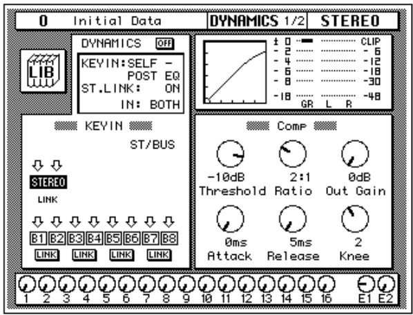
2. Press the (SEL) button for STEREO.
Note: If one of the icons B1 through B8 in the KEY IN section of the display is highlighted, it means the corresponding output bus is selected. To select the stereo bus, move the cursor to the STEREO icon using the CURSOR buttons and press the [ENTER] button.
By default (assuming you are still working with Scene Memory 0 "0 Initial Data") the dynamics processor is set to a compression program with all parameters set to the default value as shown in the table below:
| Threshold | 0 dB | Knee | hard |
| Ratio | 1:1 | Attack | 0 ms |
| Out Gain | 0 dB | Release | 5 ms *1 |
*1 This value is obtained when the sampling frequency is 48kHz .
The processor is OFF.
- Use the CURSOR buttons to select the DYNAMICS OFF icon and press the (ENTER) button to turn the processor on.
The icon is highlighted with the text changed to ON. Being able to easily turn the dynamics processor on and off allows you to perform quick A-B listening tests.
- Select the KEY IN parameter with the CURSOR buttons. Rotate the encoder wheel or press the (ENTER) button to select the trigger source for the processor.
By default, the STEREO channel is triggered by itself, pre-EQ (SELF - PRE-EQ). You can select post-EQ or the signal on the aux buses, AUX 1 or AUX 2.
Note: As you change the KEY IN parameter, the icons in the KEY IN block on the display also change.
You should select either SELF - PRE-EQ or SELF - POST-EQ.
- Use the CURSOR buttons to select the compressor parameters.
- Adjust the value of each parameter by rotating the encoder wheel.
To compress the stereo output signal, try settings similar to those in the following table:
| Threshold | -10 dB | Knee | 2 |
| Ratio | 2:1 | Attack | 60 ms |
| Out Gain | 0 dB | Release | 1.02 sec *1 |
*1 This value is obtained when the sampling frequency is 44.1kHz or 48kHz .
The above settings provide a 2:1 compression above -10 dB. This means for every 1 dB change in input signal level above -10 dB there will be a 0.5 dB change in the output level. You can increase the output level without as much risk of clipping. The overall effect is the output signal sounds louder, essentially because you have limited—or compressed—the dynamic range.
Experiment with the settings until you get an effect that you like.
Using the Dynamics Library
Once you have applied a dynamics processor to the stereo bus, you need to know how to recall dynamics programs from the library and to adjust the parameters to create your own dynamics programs.
Recalling Dynamics Programs

- Use the (DYNAMICS) button to locate the DYNAMICS 2/2 page shown below.
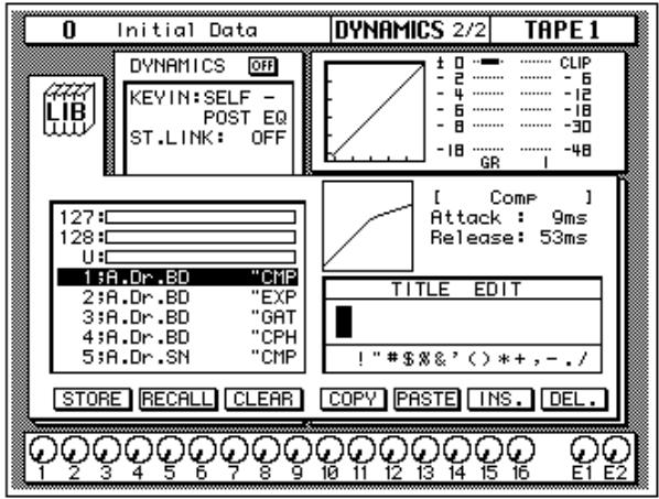
Alternatively, you could use the LIB icon on the DYNAMICS 1/2 page to go to the DYNAMICS 2/2 page.
- Use the CURSOR buttons to select the RECALL icon. Rotate the encoder wheel to select a dynamics program.
The 02R will scroll through the available dynamics programs. The program that is highlighted is the program that will be recalled when you press the [ENTER] button.
- Press the (ENTER) button.
The dynamics program is recalled.
If you attempt to recall a user program that is empty, the 02R displays an error message, indicating that the selected memory location is not available for recall.
Note: Unlike EQ and effects, it is sometimes necessary to apply a dynamics processor to an input signal as you are recording multitrack sources. Some signals are too unpredictable or noisy to record without some form of compression or gating. However, you should be very selective about the dynamics you apply, as the same rule holds: it is easy to add the effect, but very difficult to remove it afterwards.
Editing Dynamics Programs
You can edit the preset dynamics programs and then store them as user programs. The 02R has 40 preset programs (1 through 40). Each program is a variation on the six basic dynamics processors available:
- Compressor (CMP)
- Gate (GAT)
- Expander (EXP)
- Compander - Hard (CPH)
- Compander - Soft (CPS)
Ducking (DUK)
Select the preset dynamics program that is closest to the effect you are trying to achieve and edit its parameters. For a list of the preset programs, see "Preset Dynamics Programs" on page 76 of the User's Guide.
Note: The program name of each preset dynamics program contains a three letter code indicating the type of dynamics processor it is.
- Use the (DYNAMICS) button to locate the DYNAMICS 1/2 page shown below.
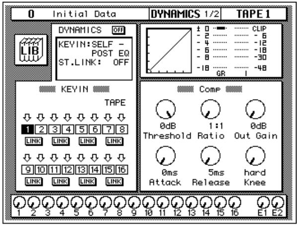
Alternatively, you could use the LIB icon on the DYNAMICS 2/2 page to go to the DYNAMICS 1/2 page.
- Select the various parameters with the CURSOR buttons, and adjust the values with the encoder wheel.
After you have modified the dynamics program to your satisfaction, you are ready to store it.
Storing a User Dynamics Program
The 02R has 88 user dynamics program locations (41 through 128) for you to store your own settings. You can store your dynamics program in the Dynamics Library, or you can just rely on the 02R scene memory to recall your settings. The following instructions show you how to store your program in the library.
- Use the (DYNAMICS) button to locate the DYNAMICS 2/2 page shown below.
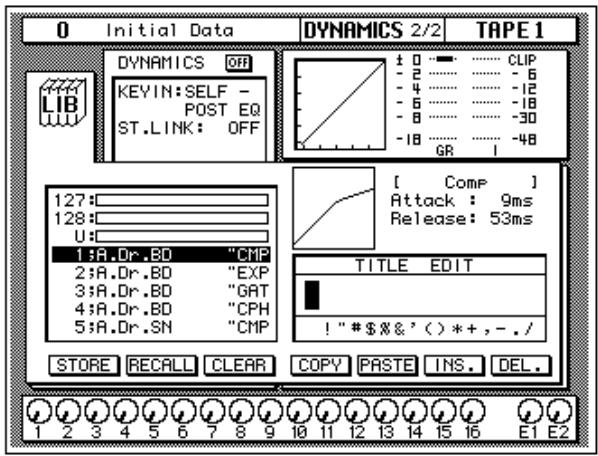
Alternatively, you could use the LIB icon on the DYNAMICS 1/2 page to go to the DYNAMICS 2/2 page.
- Use the CURSOR buttons to select the TITLE EDIT box.
- Select the individual character positions with the CURSOR buttons. Use the encoder wheel to select the characters.
You can create a name of up to 16 characters long. It can contain any of the following characters:
| ! | “ | # | $ | % | & | ' | ( | ) | * | + | , | - | . | / | |
| 0 | 1 | 2 | 3 | 4 | 5 | 6 | 7 | 8 | 9 | : | ; | < | = | > | ? |
| @ | A | B | C | D | E | F | G | H | I | J | K | L | M | N | O |
| P | Q | R | S | T | U | V | W | X | Y | Z | [ | \ | ] | ^ | _ |
| ` | a | b | c | d | e | f | g | h | i | j | k | I | m | n | o |
| p | q | r | s | t | u | v | w | x | y | z | { | | | } | ~ |
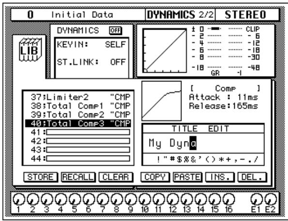
You can select the "INS." icon to insert a space (blank) at the current cursor position in the TITLE EDIT box. Select the icon with the CURSOR buttons and press the [ENTER] button. The "DEL." icon is used to delete the character at the cursor position.
Note: The "COPY" and "PASTE" icons allow you to select the title from another dynamics program and paste it into your program for subsequent editing. These icons only copy the title, not the dynamics settings. See "Icons" on page 88 of the User's Guide.
4. Use the CURSOR buttons to select the STORE icon. Rotate the encoder wheel to select a dynamics program.
If you select one of the preset programs (1 to 40), the message "Preset is read only!", appears when you attempt to store your program. Select a program from the 88 user programs (41 to 128). You cannot store your settings to program "U" (the UNDO buffer) either.
5. Press the (ENTER) button.
The 02R will display a confirmation dialog box asking if you want to store your settings in the selected dynamics program. The dialog box has two icons: "CANCEL" and "EXECUTE".
Note: You can customize your 02R to prevent the confirmation dialog box appearing during STORE operations. See “Preferences” on page 198 of the User's Guide for more information.
CANCEL is the default. To cancel the STORE operation, either press the [ENTER] button or wait about 10 seconds—the STORE operation will be automatically cancelled.
To store your settings, use the CURSOR buttons to select the "EXECUTE" icon and press the [ENTER] button. The dynamics program is stored.
Note: If you decide you do not like a dynamics program after you have stored it, it is very easy to overwrite it by creating new settings and storing them to the same location. Conversely, it is also very easy to accidentally overwrite a valued dynamics program.
YOU SHOULD ALWAYS BE CAREFUL WHEN THE 02R DISPLAYS A CONFIRMATION_DIALOG BOX!
Scene Memories
The 02R scene memories are a snapshot of all the digital parameters of the mixer. The 02R has 96 mix scene memory locations. Each can be named for easy identification.
There are two special scene memories. "0 Initial Data" is a read-only scene memory that resets the 02R to its default settings. The other is an undo buffer entitled "U". Recalling the undo buffer restores the last state of the 02R.

STORE


RECALL
SCENE MEMORY
Scene memories can be stored and recalled using the [STORE] and [RECALL] buttons. Scene memories are selected using the SCENE MEMORY increment or decrement buttons.
They can also be recalled using automix or by using MIDI Program Changes from a computer, MIDI sequencer, or MIDI footswitch. You can save scene memories to a MIDI data file.
Storing a Scene Memory
When you store a scene memory, you should check that all the mixer settings in the Edit Buffer are correct. Some settings may have been adjusted accidentally, or by someone else. If you are not sure about the exact contents of the mixer and do not want to laboriously check each setting, recall the initial mixer settings (Scene Memory 0 "0 Initial Data"), make the adjustments that you really want, and then store.
Note: You may want to store the current mix settings to an unused scene memory, just in case.
1. Use the SCENE MEMORY increment or decrement buttons to select a scene memory.
You cannot store your settings to either of the special scene memories: "U" (the UNDO buffer) or "0 Initial Data". If you select these scene memories, an error message appears when you attempt to store your scene memory.
When you select a new scene memory, the number displayed in the SCENE MEMORY LED indicator flashes.
2. Press the (STORE) button.
The 02R displays a confirmation dialog box asking if you want to store your settings in the selected scene memory. The dialog box has two icons: "CANCEL" and "EXECUTE".
Note: You can customize your 02R to prevent the confirmation dialog box appearing during STORE operations. See “Preferences” on page 198 of the User's Guide for more information.
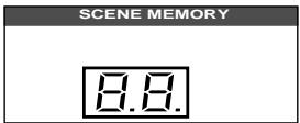
CANCEL is the default. To cancel the STORE operation, either press the [ENTER] button or wait about 10 seconds—the STORE operation will be automatically cancelled.
To store your settings, use the CURSOR buttons to select the "EXECUTE" icon and press the [ENTER] button.
The scene memory is stored.
Note: If you decide you do not like a scene memory after you have stored it, it is very easy to overwrite it by adjusting the mixer settings and storing them to the same location. Conversely, it is also very easy to accidentally overwrite a valued scene memory. The 02R has a "Memory Protect" feature to help prevent this, but this feature can interfere with your work, plus it is very easy to turn off the protection. See "Protecting Scene Memories" on page 134 of the User's Guide
YOU SHOULD ALWAYS BE CAREFUL WHEN THE 02R DISPLAYS A CONFIRMATION Dialog Box!
Naming a Scene Memory
Scene memories can be named before being stored or after. In the latter case, you must first recall the scene memory, name it, and then store it. In this tutorial, a scene memory that has already been stored is named.

SCENEMEMORY
- Use the (SCENE MEMORY) button to locate the SCENE 1/5 page shown below.
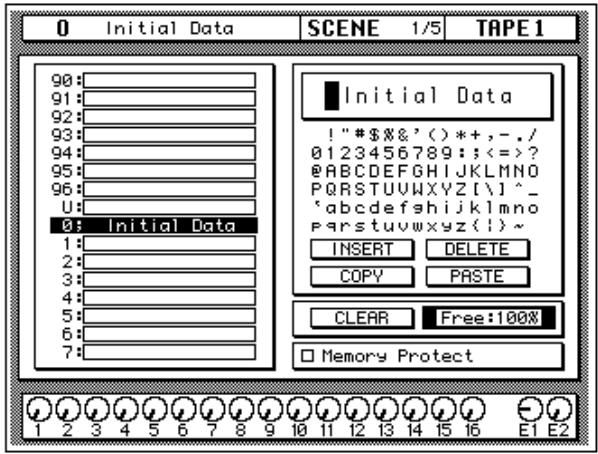
- Use the SCENE MEMORY increment or decrement buttons, or encoder wheel, to select the scene memory.
When you select a different scene memory, the number displayed in the SCENE MEMORY LED indicator flashes.
- Press the (RECALL) button to recall the scene memory.
- Use the CURSOR buttons to select the TITLE EDIT box.
5. Select the individual character positions with the CURSOR buttons. Use the encoder wheel to select the characters.
You can create a name of up to 16 characters long. It can contain any of the following characters:
| ! | “ | # | $ | % | & | ' | ( | ) | * | + | , | - | . | / | |
| 0 | 1 | 2 | 3 | 4 | 5 | 6 | 7 | 8 | 9 | : | ; | < | = | > | ? |
| @ | A | B | C | D | E | F | G | H | I | J | K | L | M | N | O |
| P | Q | R | S | T | U | V | W | X | Y | Z | [ | \ | ] | ^ | _ |
| ` | a | b | c | d | e | f | g | h | i | j | k | l | m | n | o |
| p | q | r | s | t | u | v | w | x | y | z | { | | | } | ~ |
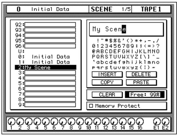
You can select the "INSERT" icon to insert a space (blank) at the cursor position in the title edit box. Select the icon with the CURSOR buttons and press the [ENTER] button. The "DELETE" icon is used to delete the character at the cursor position.
Note: The "COPY" and "PASTE" icons allow you to copy the title from another scene memory and paste it into the title edit box for subsequent editing. If you use the Copy function, be sure to select the scene memory whose name you are editing before storing. Otherwise, you'll overwrite the scene whose name you copied.
6. Press the (STORE) button.
If you respond to the confirmation dialog box by selecting "EXECUTE" and pressing the [ENTER] button, the scene memory is stored with its new name.

STORE


SCENE MEMORY
Recalling a Scene Memory
Scene memories are recalled using the [RECALL] button. They can also be recalled using the automix or by using MIDI Program Change Messages.
1. Use the SCENE MEMORY increment or decrement buttons to select the desired scene memory.
When you select a different scene memory, the number displayed in the SCENE MEMORY LED indicator flashes.
2. Press the (RECALL) button.
The selected scene memory is recalled.
Note: When recalling mix scenes, be aware that volume levels may change suddenly as channels are switched ON and faders moved. The 02R has a feature that allows you to fade the levels as a scene memory is loaded, but it cannot compensate for the sudden burst of a channel suddenly being switched on. See "Fade Time" on page 136 of the User's Guide for further information.
When the scene memory is recalled, the number displayed in the SCENE MEMORY LED indicator stops flashing.
If you attempt to recall a scene memory that is empty, the 02R displays an error message, indicating that the selected memory location is not available for recall.
5
Mixing and Automix
In this chapter...
What is 02R Automix? 68
Real-time Automix 69
Editing Automix Events 76
Off-line Automix Editing 81
Using the Automix Library 87
What is O2R Automix?
There are three basic steps to making a multitrack recording:
- Setup and initial tracks
Overdubbing - Mixdown
Each step is vital in order to produce a satisfactory recording, but the most difficult one for most engineers is the mixdown. The musicians have finished their work. They have played their instruments and sung their vocals. All that raw material is stored on your multitrack recorder, waiting to be turned into a perfect final mix.
To assist you with this difficult task, the 02R has a fully-featured on-board automix system. It memorizes fader position changes, switches individual channels on or off, adjusts the EQ or pan positions, and changes the auxiliary sends—all based on timecode. It can also recall scene memories and programs from the EQ library, effects library, dynamics library, and channel library.
This allows you to record an entire mixing session, and then edit the individual channel settings in multiple passes until you have achieved perfection. You can punch-in to fine tune a specific parameter or you can use one of the event editors to adjust the timecode position of a channel setting or scene change. You can easily create a mix that would be virtually impossible to achieve on a standard analog mixer.
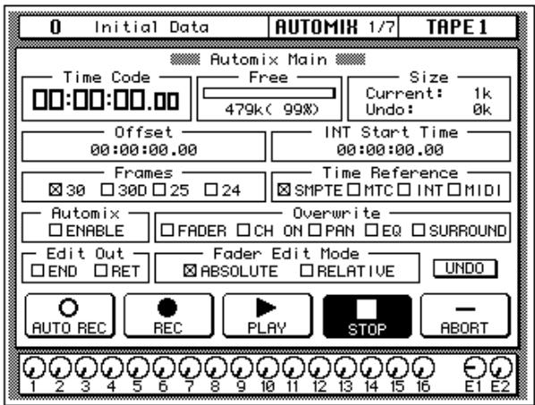
Automix Memory
The 02R has a current automix buffer and 16 automix memories. There is also an undo buffer. Only the current mix can be played back and recorded. You can store the current mix in any of the 16 automix memories.
Real-time Automix
These tutorials have assumed you are using your 02R with one or more of the optional I/O cards installed and a multitrack recorder connected. In this section, you will be synchronizing your multitrack recorder to the 02R. There are three basic ways of doing this:
- If your multitrack recorder is equipped with a SMPTE timecode output connector, you use an audio cable to connect it to the SMPTE TIME CODE INPUT jack on the rear panel of the 02R.
- Use an external SMPTE timecode generator if your multitrack recorder cannot output SMPTE time. You need to record timecode onto one of the tracks of your multitrack recorder and connect the output from that track directly to the SMPTE TIME CODE INPUT jack on the rear panel of the 02R.
- Use a MIDI sequencer to send MTC (MIDI timecode) or MIDI Clocks to the 02R as well as your multitrack recorder. Connect a MIDI cable to the MTC TIME CODE INPUT jack on the rear panel of the 02R.
There is an additional option--you can automate the 02R using its internal timecode generator. However, you cannot synchronize with an external device as the 02R has no timecode output connectors. This mode is effective for learning how to use the automix system.
Basic Connections and Setup
- Connect your timecode source to the 02R.
- Use the (AUTOMIX) button to locate the AUTOMIX 1/7 page.

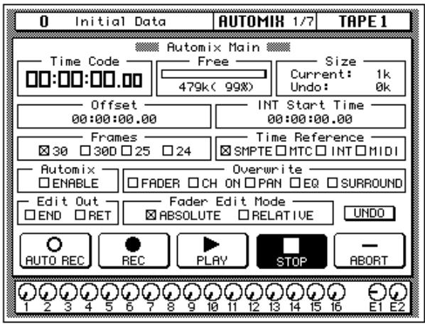
- Use the CURSOR buttons to select the desired "Frames" rate and press the (ENTER) button.
The 02R supports the following frame rates:
30-30 frames per second.
30D—29.97 frames per second (30 drop frame).
25-25 frames per second.
24—24 frames per second.
These frame rates apply to the SMPTE, MTC, and INT time references.
4. Select the "Time Reference" with the CURSOR buttons and press the (ENTER) button.
Select the time reference from the four options:
- SMPTE timecode (the motion picture standard)
MTC (MIDI timecode) - INT (internal)
MIDI (MIDI Clock)
5. Use the CURSOR buttons to select the "Automix" ENABLE and press the (ENTER) button to switch it on.
The automix system will not function unless this check box is enabled.
6. Select the desired "Overwrite" items with the CURSOR buttons and press the (ENTER) button.
This field allows you to select the types of events that will be recorded. Only the items selected will be recorded. Choose from the following:
- FADER—channel level operations (fader or encoder) including auxiliary send levels.
- CH ON—[ON] button selections for each channel.
PAN—pan position for each channel. - EQ—EQ selections for each channel.
- SURROUND—surround pan events
Note: Scene memories and all library recall operations will be recorded regardless of the settings of the "Overwrite" options.
The other options on this page are also important, but not for the purposes of this tutorial. See "Automix Main" on page 144 of the User's Guide for more details.
Creating a New Automix
To record an entire mixing session with the 02R automix system, you must first create a new automix. When a new automix is created, the contents of the current automix (referred to as "events") are deleted and the current automix is returned to its default settings.

If you want to keep the contents of the current automix, store them into an available memory location before proceeding.
- Use the (AUTOMIX) button to locate the AUTOMIX 2/7 page.
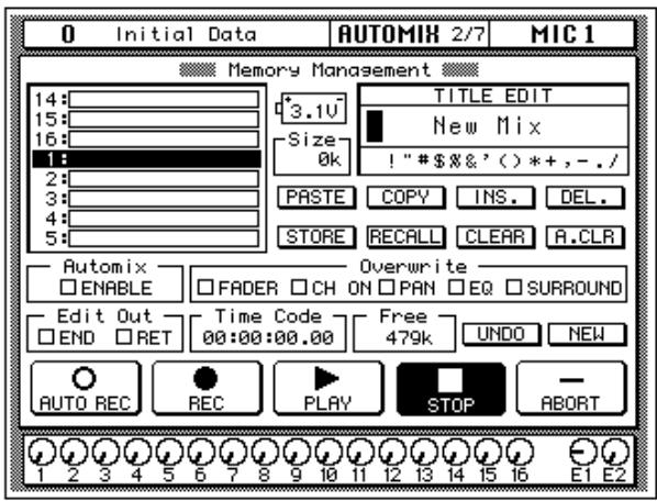
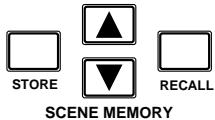
- Use the SCENE MEMORY increment or decrement buttons to select your starting scene memory and press the (RECALL) button.
The selected scene memory is recalled.
Your mixdown scene memory should be stored with the [FLIP] button pressed so that the faders operate the tape returns rather than the input channels.
Note: You can customize your 02R so that the [FLIP] button status is ignored during scene memory recalls. In this case, you may need to press the [FLIP] button before you start recording your automix. See "Preferences" on page 198 of the User's Guide for more information.
- Set your starting levels for the mixdown and press the (STORE) button to update the scene memory.
The 02R will display a popup confirmation request message. Select the "EXECUTE" icon and press the [ENTER] button.
- Use the CURSOR buttons to select the "NEW" icon and press the (ENTER) button.
The 02R will display a popup confirmation request message asking if you want to make a new automix. The popup has two icons: "CANCEL" and "EXECUTE":
Please Confirm. Make New Automix? CANCEL EXECUTE
CANCEL is the default. To cancel the NEW operation, either press the [ENTER] button or wait about 10 seconds—the NEW operation will be automatically cancelled.
To create the new automix, use the CURSOR buttons to select the "EXECUTE" icon and press the [ENTER] button. The last scene memory that was stored or recalled will be inserted at timecode location 00:00:00.00.

Recording the First Session
- Use the (AUTOMIX) button to locate the AUTOMIX 1/7 page.

- Select the "REC" (record) icon with the CURSOR buttons and press the (ENTER) button.
The "REC" icon will flash, indicating AUTOMIX RECORD READY status:
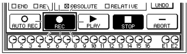
- Press the (SEL) buttons for the tape return channels you want to record.
The LED inset in the selected channel [SEL] buttons flash indicating that they are armed for recording.
Note: Remember the scene memory you recalled has the [FLIP] function engaged. Therefore you should be selecting the [SEL] buttons in the row above the faders.
- Start the device that is providing the timecode.
It should start from a location before the music starts.
Note: The 02R automix function will not respond correctly in cases where the source timecode starts at "23:59:30.00" and rolls over to "00:00:00.00". The timecode must be continuous.
When timecode is received when the 02R is in AUTOMIX RECORD READY status, the “REC” icon is highlighted and automix recording will
begin. The timecode will be displayed in real-time in the "Time Code" field of the "Automix Main" page.
Note: If the timecode is not being displayed correctly in the “Time Code” field, check the following:
- Are your cables connected between the timecode source device and the O2R correctly?
- Is the timecode source device setup correctly to output timecode?
5. While monitoring the recording, operate the faders and other controls for the selected channels.
When you are recording the automix events, you can only operate the controls, specifically the faders, of the selected channels.
Note: The 02R tries to prevent accidental level changes by "freezing" the faders that have not been selected. To avoid damaging the unit, do not attempt to operate the faders of channels that have not been selected.
Automix Recording Notes
- When you are recording pan or EQ changes you may find it more convenient to use the buttons and controls of the SELECTED CHANNEL block.
- If you have selected more than one channel with the [SEL] buttons, the SELECTED CHANNEL controls can only adjust the channel that was selected last. The same applies for EQ and dynamics processor operations. Because of these restrictions, you may find it more convenient to work on your automix recording one channel at a time when editing EQ and pan data.
- While you are recording automix events, you can select other 02R display functions, allowing you to adjust the parameters for multiple channels.
- To record a recall operation from EQ, dynamics, or channel libraries, press the [SEL] button for the channel to be changed, then use the corresponding display function to perform the recall operation. To record a recall operation from the effect libraries, use the [AUX 7] or [AUX 8] button to access the effect libraries.
6. When you have completed recording the automix session, use the CURSOR buttons to select the "STOP" icon and press the (ENTER) button.
You may find it faster and more convenient to stop the automix recording session by stopping the device that is providing the timecode. In this case, the effect is the same as if you selected the STOP function on the 02R:
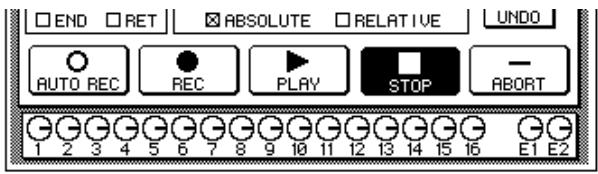
The "REC" icon will change to normal and the "STOP" icon is highlighted. The events recorded during the automix session will be written to the current automix memory.
You can also discard the events recorded during the automix session by selecting the "UNDO" icon with the CURSOR buttons and pressing the [ENTER] button.
You can stop the automix recording session by selecting the "ABORT" icon with the CURSOR buttons and pressing the [ENTER] button. However, the events recorded during the automix session will be discarded.
Note: The ABORT function must be used before an automix recording has stopped. Once the recording has stopped, the automix data will be updated and a new current mix is created. At this point after stopping an automix recording, the UNDO function can be used to retrieve the previous automix data.
In most cases, punch-in edits or using the event editors can correct minor errors.
- Stop the device that is providing the timecode.
Editing Automix Events
Overwriting Events
You can overwrite the events that have been recorded into the current automix. You can alter events on an already recorded channel or you can record new events onto another channel. For example, you may first record the faders for the rhythm section to the automix and then overwrite the fader operations for the lead parts and vocals.

- Use the (AUTOMIX) button to locate the AUTOMIX 1/7 page.

WARNING! Be careful that previously recorded events are not accidentally overwritten when you make these selections.
- Use the CURSOR buttons to select the desired "Overwrite" items and press the (ENTER) button.
Note: If you double-click the [ENTER] button on a selected "Overwrite" item, only that item will be selected and the other items will be switched off. - Select the "REC" icon with the CURSOR buttons and press the (ENTER) button.
The "REC" icon will flash.
4. Press the (SEL) buttons for the tape return channels you want to overwrite.
It is very important that you be careful when you select the type of events and channels that will be overwritten. If you select the same channel and the same type of event as the last session, the previously recorded events will be deleted the moment the automix recording begins.
5. Start the device that is providing the timecode.
It should have been rewound and again start from a location before the music starts. The previously recorded automix will playback.
- While monitoring the recording, adjust the parameters you want to overwrite.
- When you have completed the automix overwriting session, use the CURSOR buttons to select the "STOP" icon and press the (ENTER) button.
You may find it faster and more convenient to stop the automix recording session by stopping the device that is providing the timecode. The effect is the same as if you selected the STOP function on the 02R.
The "REC" icon will change to normal and the "STOP" icon is highlighted. The events recorded during the overwriting session will be added to the current automix memory.
8. Stop the device that is providing the timecode.
Punch-in Automix Data
If you made a mistake in just one portion of the automix, you can replace the erroneous data with a punch-in.

- Use the (AUTOMIX) button to locate the AUTOMIX 1/7 page.
- Use the CURSOR buttons to select the desired "Overwrite" items and press the (ENTER) button.
- Select the "REC" icon with the CURSOR buttons and press the (ENTER) button.
The "REC" icon will flash.
4. Start the device that is providing the timecode.
It should have been rewound and again start from a location before the music starts. The previously recorded automix will playback, however, because you have not selected any channels, the 02R will remain in AUTOMIX RECORD READY status.
- Monitor the recording. At the punch-in location, press the (SEL) buttons for the tape return channels you want to fix.
Recording will begin from the location where you pressed the [SEL] button.
Note: From this point, new events will be recorded and previously existing events will be deleted.
- While monitoring the recording, adjust the parameters you want to fix.
- When you have finished adjusting the parameters, press the (SEL) buttons again.
The 02R will return to AUTOMIX RECORD READY status.
Note: If you do not adjust any parameters between the punch-in and punch-out points, any events of the selected type that were previously recorded there will have been deleted.
- Use the CURSOR buttons to select the "STOP" icon and press the (ENTER) button.
You may find it faster and more convenient to stop the automix recording session by stopping the device that is providing the timecode. The effect is the same as if you selected the STOP function on the 02R.
The "REC" icon will change to normal and the "STOP" icon is highlighted.
- Stop the device that is providing the timecode.
Editing Fader/Encoder Movements
If you are replacing erroneous fader/encoder data using a punch-in, the 02R allows you to monitor the differences on the Fader Edit page.
- Use the (AUTOMIX) button to locate the AUTOMIX 1/7 page.
- Use the CURSOR buttons to select the "FADER—Overwrite" item and press the (ENTER) button.

- Use the (AUTOMIX) button to locate the AUTOMIX 3/7 page.
This display allows you to watch the fader movements as dynamic bargraphs. Several features make this display convenient to use while you perform detailed fader/encoder edits.
- Use the CURSOR buttons to select "Fader Edit Out—RET" and press (ENTER) to change its value.
If the RET check box is not selected, you may want to move the fader back to its previously recorded level before you punch-out. If the RET check box is selected, the fader will automatically return to the previously recorded level when you punch out. The time it takes to return to the previous level is controlled by the "Time" field.
- Select the "REC" icon with the CURSOR buttons and press the (ENTER) button.
The "REC" icon will flash.
- Start the device that is providing the timecode.
The 02R will remain in AUTOMIX RECORD READY status.
- Monitor the recording. At the punch-in location, press the (SEL) button for the tape return channel you want to edit.
Recording will begin from where you pressed the [SEL] button.
- While monitoring the recording, adjust the fader you want to edit.
As you operate the fader, the display shows the previously recorded position as well as the new position. An arrow in the display indicates the
direction the fader has to be moved to return to the previously recorded position:

If the fader is moved to a position lower than the previously recorded position

If the fader is moved to a position higher than the previously recorded position
9. When you have finished adjusting the fader, press the (SEL) button again.
The 02R will return to AUTOMIX RECORD READY status.
10. Use the CURSOR buttons to select the "STOP" icon and press the (ENTER) button.
You may find it faster and more convenient to stop the automix recording session by stopping the device that is providing the timecode. The effect is the same as if you selected the STOP function on the 02R.
11. Stop the device that is providing the timecode.
Off-line Automix Editing
Editing Scene and Library Recall Events
The Event Edit (Scene/Lib.) page, shown below, allows you to duplicate and delete mix scene and library recall events, and insert new events. Timecode addresses can be captured on-the-fly, and new events inserted at the captured points. The Locate function provides a speedy way to locate events in a complex automix.

1. Use the (AUTOMIX) button to locate the AUTOMIX 5/7 page.
Mix scene recall events and library program recall events are listed in the Time Code, Memory, and Channel columns. Events can be moved by editing the timecode addresses, and events are resorted automatically. In the Memory column, event type and memory number can be edited. In the Channel column, the channel number for EQ, dynamics, effects, and channel library events can be edited. Mix scene events do not have a Channel value.
2. Use the CURSOR buttons to move up or down the event list, and the encoder wheel to edit values.
You can edit the following data:
- Time Code—the location of the event as a timecode value. The 02R sorts events by their timecode value.
-
Memory—the type of the event. You can select from the following events:
-
SCENE—scene memory recall. The number indicates the scene number (from 0 to 96).
- EQ.Lib.—EQ library recall. The number indicates the EQ library number (from 1 to 128).
-
DY.Lib.—dynamics library recall. The number indicates the dynamics library number (from 1 to 128).
-
EF.Lib.—effect library recall. The number indicates the effect library number (from 1 to 128).
-
CH.Lib.—channel library recall. The number indicates the channel library number (from 1 to 64).
-
Channel—the channel that the recall applies to. For scene memory recall, this field is blank.
For timecode, you can independently adjust the hours, minutes, seconds, and frames values.
3. Use the CURSOR buttons to select the Duplicated icon and press the (ENTER) button to duplicate the selected event.
The selected event can be duplicated or deleted using the DUPLICATE and DELETE icons. When the Selected CH parameter is checked, only events corresponding to the selected channel are listed, useful for editing an automix consisting of many events.
4. Use the CURSOR buttons to select the DELETE icon and press (ENTER) to delete the selected event.
When the SYNC icon is pressed, events occurring around the current timecode address are displayed. The timecode counter below the SYNC icon displays the incoming timecode. When the CAPTURE icon below that is pressed, the current timecode address is captured and displayed in the window below. Up to eight timecode addresses can be captured, and they are stored when the 02R is turned off. The parameter next to the CAPTURE icon is used to select the addresses. When the LOCATE icon is pressed, events occurring about the captured timecode address are displayed. When the INSERT icon is pressed, a new scene recall event is inserted at the captured timecode address. The new event can be edited as required.
Editing Channel On, Pan, & Fader events
The Event Edit (CH ON, PAN, FADER) page, shown below, allows you edit channel on/off, pan, and fader events, and duplicate, delete, and insert new events. Timecode addresses can be captured on-the-fly, and new events inserted at the captured points. The Locate function provides a speedy way to locate events in a complex automix.

1. Use the (AUTOMIX) button to locate the AUTOMIX 6/7 page.
Channel on/off, pan, and fader events are listed in the Time Code, and Channel columns. Events can be moved by editing the timecode addresses, and events are resorted automatically. In the Channel column, the channel number can be edited. The value in the third column depends on the event type selected using the CH ON (ON/OFF), PAN (L-C-R), and FADER (dB/SEC) check boxes.
- Use the CURSOR buttons to move up or down the event list, and the encoder wheel to edit values.
- Use the CURSOR buttons to select the Duplicated icon and press the (ENTER) button to duplicate an event.
The selected event can be duplicated or deleted using the DUPLICATE and DELETE icons. When the Selected CH parameter is checked, only events corresponding to the selected channel are listed, useful for editing an automix consisting of many events.
4. Use the CURSOR buttons to select the DELETE icon and press (ENTER) to delete the current event.
When the SYNC icon is pressed, events occurring around the current timecode address are displayed. The timecode counter below the SYNC icon displays the incoming timecode. When the CAPTURE icon below that is pressed, the current timecode addresses is captured and displayed in the window below. Up to eight timecode addresses can be captured, and they are stored when the 02R is turned off. The parameter next to the CAPTURE icon is used to select the addresses. When the LOCATE icon is pressed, events occurring around the captured timecode address are displayed.
When the INSERT icon is pressed, a new event is inserted at the captured timecode address. The type of event depends on which of the CH ON, PAN, FADER check boxes is checked. The new event can be edited as required.
Erasing Events
The Event Copy page, shown below, allows you to copy, move, erase and trim the level of automix events. In this tutorial just the Erase function is used. See "Event Copy" on page 153 of the User's Guide for information about the other functions.

AUTOMIX
- Use the (AUTOMIX) button to locate the AUTOMIX 4/7 page.
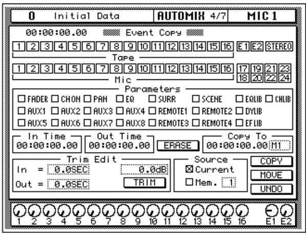
The channel icons are used to select the channels whose automix data is to be edited.
2. Use the CURSOR buttons to select the channel check boxes, and press the (ENTER) button to check them.
The Parameter check boxes are used to select parameters for editing, and multiple parameters can be selected. The parameters are:
- FADER—Channel input and output level events (faders/rotary encoders)
- CH ON—Channel on/off (mute) events
PAN—pan events - EQ—EQ events
- ScENE—Scene memory recall events
- AUX 1-8—Channel aux send events (faders/rotary encoders)
- REMOTE 1-4—MIDI Remote events
- SURR—Surround pan events
EQLIB—EQ library program recall events - CHLIB—Channel library program recall events
-
DYLIB—Dynamics library program recall events
EFLIB—Effects library program recall events -
Use the CURSOR buttons to select the parameter check boxes, and press the (ENTER) button to check them.
-
Use the CURSOR buttons and encoder wheel to set the In Time.
- Use the CURSOR buttons and encoder wheel to set the Out Time.
The Extract function allows you to delete the selected parameters from the selected channels between the In Time and Out Time points.
- Use the CURSOR buttons to select the "ERASE" icon and press the (ENTER) button.
A confirmation dialog box appears.
- Select EXECUTE and press the (ENTER) button.
The events are deleted. If you change your mind, you can restore the deleted events using the Undo function. You can undo only the last operation.
Using the Automix Library
Storing an Automix
An automix can be stored in one of the 16 automix memories available on the Memory Management page shown below.

- Use the (AUTOMIX) button to locate the AUTOMIX 2/7 page.
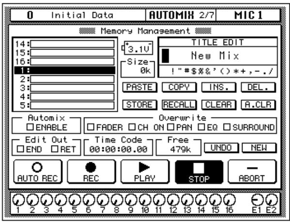
- Use the CURSOR buttons to select the TITLE EDIT box.
- Use the CURSOR buttons to move the cursor within the title, and the encoder wheel to select the characters.
Automix titles can be up to 16 characters long, and the following characters are available.
| ! | “ | # | $ | % | & | ' | ( | ) | * | + | , | - | . | / | |
| 0 | 1 | 2 | 3 | 4 | 5 | 6 | 7 | 8 | 9 | : | ; | < | = | > | ? |
| @ | A | B | C | D | E | F | G | H | I | J | K | L | M | N | O |
| P | Q | R | S | T | U | V | W | X | Y | Z | [ | \ | ] | ^ | _ |
| ` | a | b | c | d | e | f | g | h | i | j | k | I | m | n | o |
| p | q | r | s | t | u | v | w | x | y | z | { | | | } | ~ |
You can select the "INS." icon to insert a space at the cursor position in the TITLE EDIT box. Select the icon with the CURSOR buttons and press the [ENTER] button. The "DEL." icon is used to delete the character at the cursor position in the TITLE EDIT box.
Note: The "COPY" and "PASTE" icons allow you to select the title from another automix program and paste it into your program for subsequent editing. These icons only copy the title. See "AUTOMIX Name Edit Functions" on page 149 of the User's Guide.
4. Use the CURSOR buttons to select the STORE icon. Use the encoder wheel to select an automix and press the (ENTER) button.
The 02R will display a popup confirmation request message asking if you want to store your settings in the selected automix program. The popup has two icons: "CANCEL" and "EXECUTE".
CANCEL is the default. To cancel the STORE operation, either press the [ENTER] button or wait about 10 seconds—the STORE operation will be automatically cancelled.
To store your settings, use the CURSOR buttons to select the "EXECUTE" icon and press the [ENTER] button. The automix is stored.
Automix Memory
Automix memory is shared between the current automix and the stored automixes. This means that a "Memory Full" error message could appear even though there are empty automix locations. A complex automix, containing many events, may exceed the memory capacity. If this occurs, backup and delete any unused automixes and attempt the STORE operation again.
The default capacity of the 02R automix memory is 480K. You can expand this to 1.5 MB or 2.5 MB by installing the optional ME4M memory expansion kits.

Recalling an Automix
- Use the (AUTOMIX) button to locate the AUTOMIX 2/7 page.
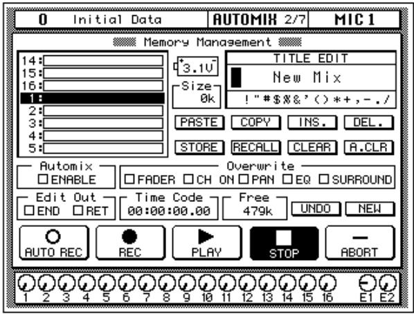
- Use the CURSOR buttons to select the RECALL icon. Use the encoder wheel to select an automix.
The 02R will scroll through the available automixes. The program that is highlighted will be recalled when you press the [ENTER] button.
- Press the (ENTER) button.
The 02R will display a popup confirmation request message asking if you want to recall selected automix program. The popup has two icons: "CANCEL" and "EXECUTE".
CANCEL is the default. To cancel the RECALL operation, either press the [ENTER] button or wait about 10 seconds—the RECALL operation will be automatically cancelled.
To recall the automix, use the CURSOR buttons to select the "EXECUTE" icon and press the [ENTER] button. The automix program is recalled.
Note: When you recall an automix program, you are overwriting the current automix. Make sure that you have backed up or stored the current automix just in case.
YOU SHOULD ALWAYS BE CAREFUL WHEN THE 02R DISPLAYS ITS CONFIRMATION POPUPMESSAGE!
| Index | D | resetting 29 |
| storing programs 32 | ||
| A | Deleting events 85 | titling programs 32 |
| Digital audio, benefits 10 | undo 31 | |
| Display 8 | Erasing events 85 | |
| Attenuation 22 | DSP 2 | Expander 54 |
| Audio quality 2 | Ducking 54 | |
| Automix | Dynamics | F |
| about 7 | about 9 | |
| editing 76 | compaender 54 | Faders 9 |
| editing faders and encoders 78 | compressor 54 | editing events 83 |
| editing scene and library recalls 81 | ducking 54 | level setting 20 |
| extracting events 85 | editing programs 58 | Features 5 |
| frame rate 69 | expander 54 | Frame rate, automix 69 |
| making new automixes 70 | gate 54 | Frequency, EQ 27 |
| memories 68 | library 57 | |
| memory expansion 88 | recalling programs 57 | G |
| off-line editing 81 | stereo output 55 | |
| overwriting 76 | storing programs 59 | Gain control, setting 21 |
| punch-in 77 | titling programs 59 | Ganging pans 39 |
| real-time operation 69 | E | Gate 54 |
| recalling automixes 89 | I | |
| recording 73 | Editing | |
| recording notes 74 | automix events 76 | Initial data 62 |
| setup 69 | dynamics programs 58 | Input level, setting 20 |
| storing automixes 87 | effects 50 | Installation 3 |
| time reference 69 | faders and encoders 78 | Interface, about 8 |
| titling 87 | on/off, pan, and fader events 83 | Internal effects, about 9 |
| what is it? 68 | scene and library recalls 81 | I/O cards 2 |
| Aux sends | Effects | |
| about 42 | about 9 | L |
| AUX buttons 42 | editing 50 | |
| selected channel AUX controls 42 | recalling programs 49 | LCD 8 |
| setting send levels 43 | returns 47 | Library |
| send levels 46 | dynamics 57 | |
| storing user programs 51 | effects 49 | |
| titling 51 | EQ 30 | |
| using 46 | ||
| B | EQ | M |
| Basic setup 15 | ||
| about 10 | ||
| C | applying 24 | Memory expansion kit 88 |
| bandwidth 28 | MIDI Clock 69 | |
| Compander 54 | frequency 27 | Monitoring 45 |
| Compressor 54 | gain 25 | Monitor source, setting 20 |
| Converters 11 | library 30 | Motorized faders 9 |
| Crystal clarity 2 | on/off 24 | MTC 69 |
| Q 28 | Muting channels 23 | |
| recalling programs 30 | ||
| N | selecting 37 using 36 | U |
| Naming See Titling. | Undo | |
| Noise gate 54 | S | EQ recall 31 User guides, about 3 |
| O | Scene memories about 7 | User interface, about 8 |
| Off-line editing 81 | editing recall events 81 | W |
| ON buttons 23 | indicator 23 | |
| On/off event editing 83 | recalling 65 | Wordclock 16 |
| Options 6 | recalling scene 0 17 | |
| Overwriting automix events 76 | storing 62 | Z |
| titling 63 | ||
| P | Scene memory buttons 62 | 02R |
| Scene 0 17 | features 5 | |
| Pad 21 | Setting | installation 3 |
| Pan | aux send levels 43 | options 6 |
| about 38 | effects send levels 46 | rear panel 4 |
| editing events 83 | EQ 24 | top panel 4 |
| ganging 39 | fader levels 20 | |
| setting 38 | gain controls 21 | |
| Parametric EQ, about 10 | input levels 20 | |
| Peak hold 22 | monitor source 20 | |
| Phase 22 | pan 38 | |
| Powering on/off 16 | SMPTE 69 | |
| Programs | Snapshots 62 | |
| dynamics 57 | Sonic performance 2 | |
| effects 49 | Storing | |
| EQ 30 | automixes 87 | |
| Punch-in, automix 77 | dynamics programs 59 | |
| effects programs 51 | ||
| Q | EQ programs 32 | |
| scene memories 62 | ||
| Q, EQ 28 | Switching the 02R on/off 16 | |
| R | T | |
| Rear panel 4 | Time reference, automix 69 | |
| Recalling | Titling | |
| automixes 89 | automixes 87 | |
| dynamics programs 57 | dynamics programs 59 | |
| effects programs 49 | effects programs 51 | |
| EQ programs 30 | EQ programs 32 | |
| scene memories 65 | scene memories 63 | |
| Resetting the EQ 29 | Top panel 4 | |
| Returns, effects 47 | turning channels on/off 23 | |
| RISC technology 3 | Turning the 02R on/off 16 | |
| Routing about 35 |
O2R
DIGITAL RECORDING CONSOLE
Version 2
User's Guide
Contents at a Glance
1 Controls and Connections. 1
2 User Interface 17
3 Mixing and Monitoring. 25
4 MIXING Display Functions 31
5 Surround Pan. 63
6 Dynamics 75
7 Auxiliary Channels. 97
8 Internal Effects 103
9 Scene Memories. 127
10 Automix. 137
11 MIDI 157
12 Groups and Pairs 181
13 Digital I/O, Setup, and Utilities. 187
14 Installing Options 217
15 Specifications 239
16 Glossary. 289
Index 297
Contents
1 Controls and Connections. 1
Front Panel 2
Rear Panel. 11
Block Diagram 15
2 User Interface 17
About the User Interface 18
DISPLAY ACCESS Buttons 18
Display 20
CURSOR Buttons 21
Encoder Wheel. 21
ENTER Button 21
SCENE MEMORY Buttons 21
Display Functions 22
SELECTED CHANNEL Controls 23
3 Mixing and Monitoring. 25
Analog Inputs 26
Phantom Power 26
Pad. 27
GAIN Controls. 27
SEL Buttons 27
ON Buttons. 28
Faders 28
Analog Outputs. 29
Monitor Selector Switches 29
Monitor Level Controls 30
4 MIXING Display Functions 31
Phase and Attenuation 32
Delay 34
Pan and Balance. 36
PanGang 37
Stereo Width 37
PAN controls 38
Routing 39
ROUTING buttons 40
Metering 41
View 44
Channel Library. 48
EQ 51
EQ controls. 53
EQ Programs 54
EQ Library 55
Preset EQ Program Parameters. 58
Surround Pan. 63
About Surround Pan. 64
Selecting a Surround Mode 65
Panning Sounds Freely. 67
Panning Sounds Using the Trajectories 69
Linking Channels for Surround Pan 72
CSR (Center:Side Ratio) 73
Dynamics 75
Dynamics Processors 76
PresetDynamicsPrograms 76
Compressor 77
Expander. 79
Compander 80
Gate and Ducking 81
DYNAMICS Display Function 83
Patching in a Processor. 84
Dynamics Processor Meters. 85
KEY IN and LINK Indicators 86
Dynamics Library 87
PresetDynamicsProgramParameters. 90
Auxiliary Channels 97
About the 02R Auxiliaries 98
The AUX Buttons 99
Stereo Input Channels 101
AUX [ON] Button 101
AUX Pre or Post. 101
Monitor Mix. 102
8 Internal Effects 103
About Effects 104
Preset Effects Programs 105
AUX 7 and AUX 8. 106
Effects 108
Effects Library 109
Preset Effects Program Parameters. 112
9 Scene Memories. 127
What are Scene Memories? 128
What is Stored in a Scene Memory? 129
What is the Edit Buffer? 129
Initial Data and UNDO Memory 129
Storing Mix Scenes 130
Naming a Scene Memory 131
Recalling Scene Memories 134
Fader Recall Safe 135
Fade Time. 136
10 Automix 137
What is the Automix Function? 138
What is Timecode? 140
Automix Function. 143
Automix Main 144
Memory Management 148
Fader Edit. 151
Event Copy. 153
Event Edit (Scene/Lib.) 155
Event Edit (CH ON, PAN, FADER) 156
11 MIDI 157
MIDI and the 02R 158
Setup 159
Program Change Assign 160
BulkDump/Request 161
Fader Start 163
MIDI Control Change Assign 164
MIDI Remote 165
12 Groups and Pairs 181
Grouping Faders 182
Grouping Mutes 183
Pairing Channels 184
MS Decoding 186
13 Digital I/O, Setup, and Utilities. 187
WordClockSelect. 188
Input Signal Select. 190
Cascade Configuration 191
Dither 193
Slot Output Select 194
Solo 196
Preferences 198
Aux Output Select. 203
24-bit Recording 204
Input Patching 206
Oscillator. 209
Emphasis Monitor 210
Channel Status Monitor 211
Battery Check. 213
Communication Speed 214
02R System Initialization 215
14 Installing Options 217
02R Options 218
Installing 02R Options 221
Analog I/O Card—AD/DA (CD8-AD) 224
Analog I/O Card—A/D (CD8-AD-S) 224
Digital I/O Card—AES/EBU (CD8-AE/CD8-AE-S). 225
Digital I/O Card—ADAT (CD8-AT) 227
Digital Cascade Kit (CD8-CS) 229
Digital I/O Card—TDIF-1 (CD8-TDII) 234
Peak Meter Bridge (MB02). 236
15 Specifications 239
General Specifications 240
Input Specifications. 246
Output Specifications 247
Digital Input and Output Specifications 247
Dimensions. 248
Options 249
Troubleshooting 250
Error Messages 251
Appendix: MIDI 255
MIDI Data Format. 262
Parameter Change and Request Format 265
BulkDump and Request Format 273
16 Glossary. 289
References and Further Reading. 295
Index 297
1
Controls and Connections
In this chapter...
Front Panel 2
Rear Panel. 11
Block Diagram 15
Front Panel
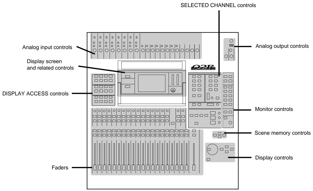
Analog input controls
1. Phantom switches (channels 1 to 8)
These switches turn the +48V DC phantom power ON and OFF for the XLR-3-31 connectors.
2. A/B switches (channels 1 to 8)
These switches select between the XLR-3-31 connectors and the phone connectors.
3. 20 dB (pad) switches (channels 1 to 16)
These switches attenuate the input signal by 20~dB
4. GAIN controls
These controls adjust the gain of the input preamp.
The analog input controls are not controlled or stored by the 02R automix and scene memory functions. To allow easy recall of the gain setting, the controls are detented.
5. PEAK LED
This red LED illuminates when the input signal exceeds 3 dB below clipping.
It is acceptable if this LED illuminates occasionally. However, if it is continuously illuminated, the input preamp is being overloaded and clipping distortion will result.
6. SIGNAL LED
This green LED illuminates when the input signal exceeds 10 dB below nominal.
Analog output controls
7. T/B LEVEL control and microphone
This control sets the volume level of the built-in talkback microphone.
8. STUDIO LEVEL control
This control sets the level of the signal sent to the STUDIO MONITOR OUTPUT connectors.
9. PHONES LEVEL control and connector
This control sets the level of signal output to a pair of stereo headphones plugged into the connector.
DISPLAY ACCESS controls
10. CONFIGURATION buttons
These buttons access the corresponding Display function.
| Button | Description |
| SCENE MEMORY | Store and recall mix scenes. |
| DIGITAL I/O | Define the digital interconnections and word clock source, cascade parameters, and dither characteristics. |
| SETUP | Set SOLO status and preferences |
| UTILITY | Define oscillator, check battery status. |
| AUTOMIX | Store and recall automix programs. |
| MIDI | Set the MIDI channels and tables. Control bulk data transfers. |
| GROUP | Set up the fader groups. |
| PAIR | Set up channel pairs. |
11. MIXING buttons
These buttons access the corresponding Display function.
| Button | Description |
| ∅/ATT | Set phase and attenuation. |
| DELAY | Set the channel delay. |
| PAN | Set the pan position. |
| ROUTING | Set the channel routing. |
| METER | Meter the levels from the individual input channels, the tape and effect return channels, the 8 main busses, and the 8 auxiliary busses. |
| VIEW | View and set all the parameters for the selected channel and access the channel library. |
| EQ | Set the equalization and access the EQ library. |
| DYNAMICS | Set the dynamics and access the dynamics library. |
12. AUX buttons
These buttons access the corresponding Display function.
| Button | Description |
| AUX 1 to 6 | Set the channel levels to the auxiliary bus-ses. |
| AUX 7 and 8 | Set the channel levels to the auxiliary bus-ses and set the effect parameters. |
Display and related controls
13. SCENE MEMORY indicator
This 2-digit (7-segment) LED shows the currently selected Scene Memory program. It also contains the Edit Indicator, which will start flashing when the current mix scene is first adjusted.
14. FADER STATUS indicators
These LED indicators show the status of the faders. When you select the AUX buttons ([AUX 1] through [AUX 8]), the AUX LED will illuminate to indicate the faders are used to set the auxiliary send levels. The currently selected AUX button is also indicated here.
Normally, the INPUT LED is illuminated.
15. SELECTED CHANNEL indicators
The 2-digit (7-segment) LED shows the currently selected channel number for the SELECTED CHANNEL controls. The three LEDs below indicate the status of the selected channel: MIC/LINE, TAPE/RTN, or OUTPUT.
16. Graphical display
This is the 320 × 240 pixel, CFL-backlight, graphical display. It displays the system functions and their parameter values both graphically and numerically.
17. Stereo output level meters
These stereo meters consist of 21-elements per channel.
18. Contrast control
This control adjusts the contrast of the graphical display.
SELECTED CHANNEL controls
19. ROUTING buttons
These buttons set the routing for the currently selected channel.
20. AUX buttons and controls
These buttons and controls set the auxiliary send channel and level for the currently selected channel.
21. PAN buttons and controls
These buttons and controls set the pan position for the currently selected channel.
22. EQ buttons and controls
These buttons and controls set the equalization for the currently selected channel.
Monitor controls
23. STUDIO buttons
These buttons select the monitor signal sent to the STUDIO MONITOR OUTPUT connectors.
24. CONTROL ROOM buttons
These buttons select the monitor signal sent to the C-R MONITOR OUT connectors.
25. TALKBACK buttons
These buttons allow the control room to talk to the studio and to SLATE control room information to the output buses.
26. SOLO button
This button activates the SOLO bus. Use the ON buttons to select a channel to monitor.
27. C-R LEVEL
This control sets the level of the C-R MONITOR OUT connectors.
Faders
28. Tape and Effect return controls
These continuously rotary controls set the level of the tape and effect returns. The current level of a return channel is shown by the corresponding icon at the bottom of the display.
29. SEL buttons
These buttons select the individual channels. When you press one of the SEL buttons, the LED in the center of the button is illuminated.
30. ON buttons
These buttons switch the selected channel ON or OFF. When a channel is ON, the LED in the center of the button is illuminated.
When you press the SOLO button (engage the SOLO function), these buttons are used to select the monitor channels. The LEDs inset in the buttons are switched off. Press the ON buttons to select channels to send to the SOLO bus. When you press the SOLO button again (cancel the SOLO function), the prior channel status is restored and the appropriate LEDs are switched back on.
31. FLIP button
This button interchanges the functions of MIC/LINE channels 1 to 16 and TAPE RETURN channels 1 to 16. This allows you to set the tape return levels with the Faders rather than the Tape Return controls.
Holding down the FLIP button for one second activates the MIDI Remote function. See "MIDI Remote" on page 165 of the User's Guide.
32. Faders
These 100mm motorized faders set the channel level for the corresponding channel.
The faders will position themselves automatically when a scene memory snapshot is recalled, a number of faders are grouped or paired, or an automix is played back.
Scene memory controls
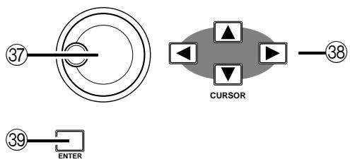
33. STORE button
This button stores the current mixer settings into the current scene memory location.
34. Increment button
This button selects the next scene memory.
35. Decrement button
This button selects the previous scene memory.
36. RECALL button
This button recalls the current scene memory. All mixer settings are restored to the positions recorded in the scene memory snapshot.
Display controls
37. Encoder wheel
This control adjusts the value of the currently selected parameter. Rotate it clockwise to increase the value, and counterclockwise to decrease the value.
38. CURSOR buttons
These buttons select the parameters and options on the display pages.
39. ENTER button
This button either confirms a parameter setting made with the Encoder wheel or it sets a parameter that only has two possible values.
Rear Panel
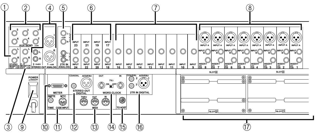
1. STUDIO MONITOR OUT connectors
These are balanced 1 / 4'' phone jacks with a +4 dB nominal output level. They output the monitor signals for the studio, and can be connected to the inputs on a monitor or headphone amplifier.
The monitor signal source is determined by the STUDIO buttons. The output level is set using the STUDIO LEVEL control.
2. AUX SEND connectors
These are unbalanced 1/4 phone jacks with a +4 dB nominal output level. They output the signals from AUX buses 1 to 6, and can be used to feed external effects processors, foldback amplifiers, or multitrack recording equipment.
3. C-R MONITOR OUT connectors
These are balanced 1/4'' phone connectors with a +4 dB nominal output level. They are wired TRS. They output the signal selected by the CONTROL ROOM buttons.
4. STEREO OUT ANALOG (1 and 2) connectors
STEREO OUT (1) are balanced XLR-3-32 type connectors with a +4 dB nominal output level. STEREO OUT (2) are unbalanced phono jacks with a -10 dBV nominal output level.
These connectors output the main stereo signals for recording, and can be connected to cassette and other analog recorders.
5. 2TR IN ANALOG (1 and 2) connectors
2TR IN (1) are balanced phone jacks with a +4 dB nominal input level. 2TR IN (2) are unbalanced phono jacks with a -10 dBV nominal input level.
Signals input here are fed through to the CONTROL ROOM buttons (24) and are monitored in the control room or the studio. The outputs of a 2-track master recorder can be connected here for confidence monitoring and playback.
6. Stereo input channels (17 to 24)
These are pairs of balanced 1/4 phone jacks with a -40 to +4 dB nominal input level. You can connect the return from a stereo effects unit to these input channels.
The signals from 2TR IN DIGITAL (1) can be routed to channels 17/18 and the signals from 2TR IN DIGITAL (2) can be routed to channels 19/20.
7. Input channels (9 to 16)
These are balanced phone jack connectors. The nominal input level is -60 dB to +4 dB. Wiring is sleeve-ground, tip-hot (+), and ring-cold (-). They can be used with balanced or unbalanced plugs.
8. Input channels (1 to 8)
INPUT A (1 to 8) are balanced XLR-3-31 type connectors. The nominal input level is -60 dB to +4 dB. They are wired according to the IEC 268 standard: Pin 1-ground, pin 2-hot (+), and pin 3-cold (-). Phantom powering is available for condenser type microphones.
Note: Make sure that the balanced devices you plug into the input connectors also use pin 2-hot, pin 3-cold wiring. If they are wired differently, undesirable phase shifts may occur. However, you can invert the phase of an input signal with the 02R.
INPUT B (1 to 8) are balanced phone jack connectors. The nominal input level is -60 dB to +4 dB. Wiring is sleeve-ground, tip-hot (+), and ring-cold (-). They can be used with balanced or unbalanced plugs. See the note above.
INSERT I/O (1 to 8) are unbalanced phone jack connectors. Both the nominal output and input levels are +0 dB. Wiring is sleeve-ground, tip-out, and ring-in. Connect external dynamic processors and other analog devices here.
9. POWER switch
This is a push-type power switch. It is recessed to prevent accidental operation. Press once to power ON; press again to power OFF.
10. METER connector
This 15-pin Dsub connector sends the meter information from each of the input channels, tape and effect return channels, auxiliary channels, etc., to the optional meter bridge (MB02).
11. TIME CODE INPUT SMPTE connector
This phone jack is a nominal -10dB / 10k connector. It accepts standard SMPTE timecode to synchronize the 02R to an external timecode source.
MTC connector
This is a standard 5-pin DIN-type MIDI connector. It is used to connect the 02R to a MIDI timecode source for external synchronization.
12. STEREO OUT DIGITAL connectors
The COAXIAL output is an RCA/phono jack. It outputs the main stereo signals for recording, and can be connected to DAT, MD, and DCC digital recorders via a 75 coaxial cable. The output format is IEC958 Part 2 (S/PDIF - Consumer).
The AES/EBU output is an XLR-3-32 type connector. It also outputs the main stereo signals for recording. The output format is IEC958 Part 3 (AES/EBU - Professional).
13. MIDI connectors
These are standard 5-pin DIN-type MIDI THRU, OUT, and IN connections. They are used to connect the 02R to external MIDI devices for sequencer synchronization and control.
14. WORD CLOCK connectors
These are TTL/75Ω BNC connectors for transmitting (OUT) and receiving (IN) word clock signals. A switch is provided to apply a 75Ω terminator to the signal if the 02R is the last device in the chain.
15. TO HOST connector
This 8-pin Mini DIN connector is to plug a Macintosh or PC into the 02R for dedicated external system control.
16. 2TR IN DIGITAL (1 to 3) connectors
2TR IN DIGITAL (1) is an XLR-3-32 type connector. The input format is IEC958 Part 3 (AES/EBU - Professional).
2TR IN DIGITAL (2 and 3) are phono jacks. The input format is IEC958 Part 2 (S/PDIF - Consumer).
Signals input here are fed through to the CONTROL ROOM buttons (24) and are monitored in the control room or the studio. The outputs of a 2-track master recorder can be connected here for confidence monitoring and playback.
Note: Digital signals routed through the control room selector switch do not have to be synchronized with the system word clock.
The signals from 2TR IN DIGITAL (1) can also be routed to stereo input channels 17/18.
The signals from 2TR IN DIGITAL (2) can be routed to stereo input channels 19/20 or directly to the stereo buss.
Note: Digital signals that are routed to the stereo input channels or directly to the stereo buss must be synchronized with the system word clock to prevent dropout and/or other noise.
17. Option slots (1 to 4)
These slots accept one of the optional I/O cards.
List of Cards
| Card | Format | Product | Size | Slot |
| Digital I/O | AES/EBU | CD8-AE | Double | 1 or 2 (max 2 cards, 16 ch) |
| CD8-AE-S | Single | 1–4 (max 4 cards, 32 ch) | ||
| ADAT | CD8-AT | Single | 1–4 (max 4 cards, 32 ch) | |
| TDIF-1 | CD8-TDII | Single | 1–4 (max 4 cards, 32 ch) | |
| YAMAHA | CD8-Y | Single | 1–4 (max 4 cards, 32 ch) | |
| Analog I/O | AD/DA | CD8-AD | Double | 1 or 2 (max 2 cards, 16 ch) |
| A/D | CD8-AD-S | Single | 1–4 (max 4 cards, 32 ch) | |
| Cascade Kit | CD8-CS KIT | Single × 2 | Any (normally 3 or 4) |
Use slots 1 and 2 for direct output lines to your multitrack recorder. See Section 14, "Installing Options" on page 217 of the User's Guide for further details.
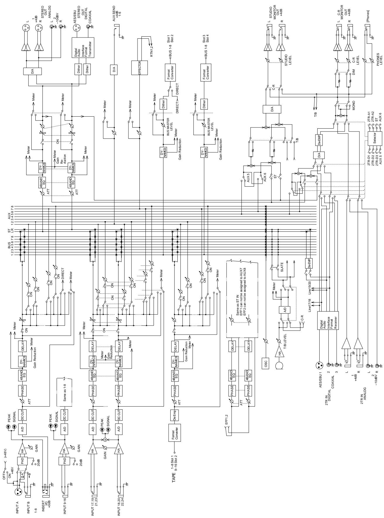
2
User Interface
In this chapter...
About the User Interface. 18
DISPLAY ACCESS Buttons 18
Display 20
CURSOR Buttons. 21
Encoder Wheel 21
ENTER Button 21
SCENE MEMORY Buttons. 21
Display Functions 22
SELECTED CHANNEL Controls 23
About the User Interface
The 02R user interface is powerful but very intuitive. There are two main methods of working with the 02R:
- Use the DISPLAY ACCESS controls to modify one parameter at a time across the entire recording console.
- Use the SELECTED CHANNEL controls to modify all of the parameters of the currently selected channel. You will find these controls similar to the setup of an analog mixer.
Use whichever method is most convenient to you. You will probably find you use a combination of both methods, dependent on what you are trying to do with the 02R.
The DISPLAY ACCESS controls consist of a block of twelve function buttons divided into three groups: the CONFIGURATION group, the MIXING group, and the AUX group, plus the large backlit graphical display, four CURSOR buttons, a detented encoder wheel, and the [ENTER] button. There is also a related block of four SCENE MEMORY buttons.
The SELECTED CHANNEL controls consist of four main blocks of controls, each block corresponding to the equivalent controls on an analog mixer. The ROUTING block selects the buss onto which to route the current channel signal. The AUX block selects the auxiliary buss to send the channel signal to and sets the send level. The PAN block sets the pan position of the channel signal. The EQ block sets the equalization curve for the current channel.
The biggest difference between the two methods is that the DISPLAY ACCESS functions are directly associated with one or more pages on the display. The following section will briefly explain each of the controls of the two main blocks. Later sections will give more details about how to use these controls.
DISPLAY ACCESS Buttons
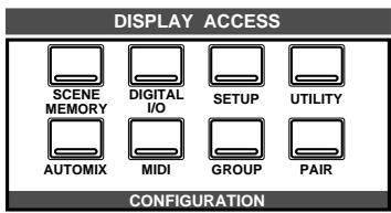
CONFIGURATION group
These buttons access the Display Functions that control the system configuration of the 02R.
-
The [SCENE MEMORY] button is used to examine and edit the scene memories. You can also set channels to "recall safe", which means they will not change levels when the scene is recalled, and you can set recall fade time.
-
The [DIGITAL I/O] button is used to select the word clock source, define the digital input/output connectors, control the cascade configuration, and set the word dither.
- The [SETUP] button is used to control the solo function and defines system preferences.
- The [UTILITY] button is used to set the oscillator function and check the battery, emphasis, and channel status monitors.
- The [AUTOMIX] button is used to set and control the automix parameters.
- The [MIDI] button is used to select the MIDI channels and MIDI functions.
- The [GROUP] and [PAIR] buttons are used to create fader and mute groups and pair channels together.
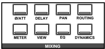
MIXING group
These buttons access the Display Functions that set mixer parameters for the entire recording console.
- The [ / ATT] button is used to reverse the phase and attenuate the signals after they have been converted to digital.
- The [DELAY] key is used to apply a small delay to the input signal, for example, to compensate for the gap between the record and playback heads of your multitrack recorder.
- The [PAN] button is used to adjust the pan position for a group of channels.
- The [ROUTING] button selects the routing page - a large visual patch bay.
- The [METER] button is used to meter the individual channels.
- The [VIEW] button is used to adjust all the parameters for the selected channel. It also accesses the Channel library.
- The [EQ] button is used to view the equalization curve and parameters of each individual channel. It also accesses the EQ library.
- The [DYNAMICS] button is used to adjust the dynamics of each individual channel. It also accesses the Dynamics library.
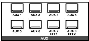
AUX group
These buttons access the Display Functions that set the auxiliary send levels for the recording console.
- The [AUX 1] to [AUX 6] buttons set the auxiliary send levels to the corresponding auxiliary buss. You can also select whether to send the signal pre or post fader.
- The [AUX 7] and [AUX 8] buttons also set the send levels to the corresponding auxiliary bus and can select pre or post fader. However,
these two sends are routed to the internal effects unit. Therefore, the buttons also allow you to select and set the effects parameters.
Display
The large backlit 320 × 240 pixel graphical display provides clear indication of mix settings and operating status. As well as showing parameter values numerically, faders and rotary controls are represented graphically, so you can actually see pan positions and fader positions. In addition, EQ curves are displayed graphically and signal levels are metered. The following illustration shows information that is always displayed and explains what it means:
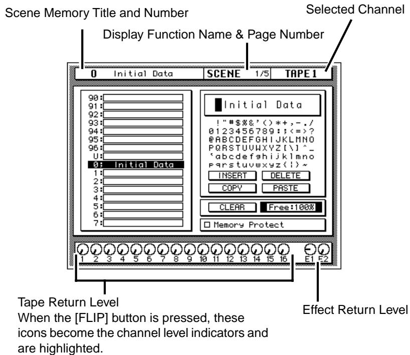
The page number shows how many pages are available within the selected function and which one of those pages is currently selected. For example, SCENE 1/3 indicates that the first page of the three SCENE pages is selected.
The CONTRAST control allows you to adjust the contrast of the display for different environments.
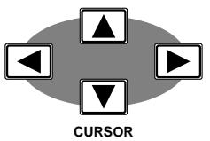
CURSOR Buttons
The CURSOR buttons are used to select parameters and options on the display. The selected parameter or option usually appears highlighted.
The CURSOR buttons are also used to position the cursor in a name when naming automix mixes, scene memories, EQ programs, effects programs, dynamics programs, and channel library programs.
When a display left or right icon appears at the left or right side of a page, indicating that another display page is available, the CURSOR buttons are used to select that display.

Encoder Wheel
The encoder wheel is used to adjust the parameter selected using the CURSOR buttons. Its detented action gives it a positive feel, allowing quick and accurate parameter adjustments. Turning it clockwise increases the selected parameter value. Turning it counterclockwise decreases the selected parameter value. The faster you turn it, the faster the parameter value changes.
The encoder wheel is also used to scroll through the automix programs, mix scenes, effects programs, EQ programs, and dynamics processor programs. When naming automixes, mix scenes, user effects programs, user EQ programs, and user dynamics programs, the encoder wheel is used to scroll through the available characters.

ENTER Button
The [ENTER] button is used to confirm settings made using the encoder wheel and to toggle two-option parameters such as EQ ON/OFF.
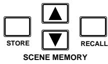
SCENE MEMORY Buttons
These buttons allow you to select, store and recall scene memories. The current scene memory is indicated on the SCENE MEMORY LED.
Display Functions
The following table lists all the 02R display functions and briefly explains what they do.
| Display Function | Description |
| SCENE | Store and recall mix scenes. |
| DIGITAL I/O | Sets digital I/O parameters and selects word clock. |
| SETUP | Sets the solo parameters and system preferences. |
| UTILITY | Controls the oscillator parameters and accesses the emphasis monitor, the channel status monitor, and the battery level check. |
| MIDI | Set the MIDI channels, build the program change table, and control MIDI bulk data transfers. |
| AUTOMIX | Create, store, recall, and play automix programs. |
| GROUP | Set up the fader and mute groups. |
| PAIR | Set up channel pairs. |
| Ø/ATT | Set phase and attenuation. |
| DELAY | Set the channel delay. |
| PAN | Set the pan position. |
| ROUTING | Set the channel routing. |
| METER | Meter the levels from the individual input channels, the tape and effect return channels, the 8 main busses, and the 8 auxiliary busses. |
| VIEW | Set all parameters for the selected channel and access the channel library. |
| EQ | Set the equalization and access the EQ library. |
| DYNAMICS | Set the dynamics processor and access the dynamics library. |
| AUX 1 to 6 | Set the channel levels to the auxiliary busses. |
| AUX 7 and 8 | Set the channel levels to the auxiliary busses and set the internal effect parameters. |
SELECTED CHANNEL Controls
These controls are very similar in setup to the controls of an analog mixer. You may find working with the buttons and controls of this section of the 02R is much faster and more intuitive than working through the pages of the DISPLAY ACCESS functions.
ROUTING buttons
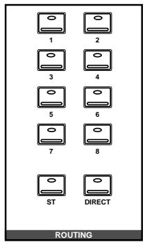
The routing buttons allow you to directly select the destination for the selected channel. The LEDs in the buttons illuminate to indicate the status of the channel.
Note: You can customize your 02R so that when you adjust any of the controls in this group, the display switches to the ROUTING page. See "Preferences" on page 198 of the User's Guide.
AUX controls
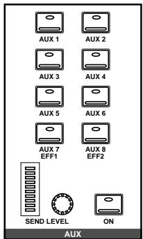
The AUX buttons allow you to select the auxiliary buses you want to send the selected channel signal to. The SEND LEVEL rotary encoder is used to set the level —indicated by the adjacent LED bargraph. The [ON] button is used to turn the send on or off. This allows you to make quick A-B comparisons.
PAN controls
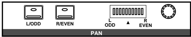
These controls allow you to set the pan position of the selected channel. The [L/ODD] and [R/EVEN] buttons select the left/odd and right/even channels. Use the rotary encoder to adjust the pan position. The current position is indicated on the adjacent LED bargraph.
Note: You can customize your 02R so that when you adjust any of the controls in this group, the display switches to the PAN page. See “Preferences” on page 198 of the User's Guide.
EQUALIZER controls
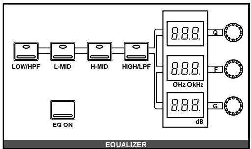
These controls allow you to adjust the EQ of the selected channel. Select the band you want to adjust with one the buttons in the top row: [LOW/HPF], [L-MID], [H-MID], or [HIGH/LPF]. The three LED indicators will reflect the status of the selected band. Adjust the values (Q, F, and G) with the adjacent rotary encoders. Use the [EQ ON] button to turn the EQ on or off.
Note: You can customize your 02R so that when you adjust any of the controls in this group, the display switches to the EQ page. See "Preferences" on page 198 of the User's Guide.
3
Mixing and Monitoring
In this chapter...
Analog Inputs. 26
Phantom Power 26
Pad 27
GAIN Controls. 27
SEL Buttons. 27
ON Buttons. 28
Faders 28
Analog Outputs 29
Monitor Selector Switches 29
Monitor Level Controls. 30
Analog Inputs
The 02R is equipped with 24 analog input connectors. The first sixteen channels, 1 through 16, are mono input channels designed for microphone to line level signal inputs. The last eight channels, 17 through 24, are stereo channels designed for line level signals only.
| INPUT 23 | INPUT 21 | INPUT 19 | INPUT 17 | |||||||||||||||||||||||||||||||||||||
| INPUT 24 | INPUT 22 | INPUT 20 | INPUT 18 | INPUT 16 | INPUT 15 | INPUT 14 | INPUT 13 | INPUT 12 | INPUT 11 | INPUT 10 | INPUT 9 | INSERT I/O dB | I/O dB | INSERT I/O dB | I/O dB | INSERT I/O dB | I/O dB | INSERT I/O dB | I/O dB | INSERT I/O dB | I/O dB | I/O dB | I/O dB | I/O dB | I/O dB | I/O dB | I/O dB | I/O dB | I/O dB | I/O dB | I/O dB | I/O dB | I/O dB | I/O dB | I/O dB | I/O dB | I/O dB | I/O dB | I/O dB | I/O dB |
In addition, the first eight channels not only have selectable input connectors, XLR-type or phone, but they also have an insert connector, allowing you to patch external signal processors before the input signal is converted to digital.
For monitoring the output of a stereo tape recorder or another similar analog device, the 02R also has two pairs of 2TR IN phone connectors.
Phantom Power
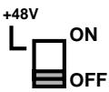
Phantom power provides a +48V DC power source for condenser type microphones. It is applied to the XLR-type connectors (INPUT A) for input channels 1 through 8. The phantom power switch for each channel is used to turn it ON and OFF. Phantom power is applied to each individual input.

Phantom power can only be applied to the XLR-type connectors (INPUT A) for input channels 1 through 8. Select those connectors with the A/B switch: up for A, down for B.
With phantom power set to ON, non-phantom powered microphones, dynamic microphones, and balanced line-level sources can still be connected to INPUT A connectors for input channels 1 through 8. However, be careful with unbalanced sources.
Pad

The Pad function attenuates input signals by 20 dB. This is useful when inputting high level signals that would otherwise overload the input preamplifier. By increasing the effective range of the GAIN control, high-level signals can be adjusted accurately. Pad can be set individually for the mono input channels 1 through 16. The [20 dB] (pad) switch at the top of each channel is used to turn it ON and OFF: up for OFF, down for ON.
GAIN Controls
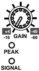
The GAIN controls are used to optimize the input channel signal levels. Use them with the PEAK indicators. This red LED illuminates when the input signal exceeds 3 dB below clipping. Ideally the level should be set relatively high. It is acceptable if this LED illuminates occasionally. If it is continuously illuminated, however, back off the GAIN control a little, otherwise the input preamplifier is being overloaded and clipping distortion will result.
The GAIN control should be set with some care. If it is set too low, the signal-to-noise performance will suffer, and if it is set too high, unpleasant signal clipping and distortion may occur.
The SIGNAL indicator is a green LED which illuminates when the input signal exceeds 10 dB below nominal.
The analog input controls are not controlled or stored by the 02R automix and scene memory functions. To assist in easy recall of the gain setting, the GAIN controls are detented. You should note the analog settings on a copy of the User Settings Sheet at the back of the manual.
SEL Buttons

The [SEL] buttons are used to select a channel in order to perform some action on it. When a channel is selected, the LED set in the corresponding button lights up and its name appears in the Selected Channel area of the display. Stereo-pair channels are selected together.
Note: You can use the [SEL] buttons to create stereo-pair channels. Refer to "Pairing Channels" on page 184 of the User's Guide.
The SELECTED CHANNEL controls are set to the current status of the selected channel. Depending on which display function is active, the selected channel may be highlighted, or the entire display may be dedicated to its parameters.
ON Buttons

The [ON] buttons are used to turn channels on and off. The input channel, tape return channel, effect return channel, and stereo output [ON] buttons turn their respective channels on and off. When a channel is turned on, the LED set in the corresponding button lights up. When it is turned off, the LED goes off. Stereo-pair channels are turned on and off together.
Faders
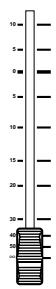
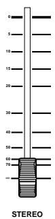
The 02R's faders are motorized. This means that they can be positioned automatically. You can group or pair faders together so all faders in a group or pair move automatically when you move any fader in that group or stereo pair.
Fader positions are stored in scene memories. When a scene memory is recalled the faders automatically move to their stored positions.
Fader positions are stored when the 02R is powered OFF. Even if faders are subsequently moved, they return automatically to their last positions when the 02R is powered ON again.
Note: You should avoid placing objects on the 02R that may block fader movements. There are several operations, such as recalling a scene memory, selecting the auxiliary buses, and automix playback, that automatically move the faders. If a fader is blocked, it could be damaged as it attempts to move.
Rotary Encoders

To adjust the levels of the tape and effect return channels, the 02R provides a continuously rotary encoder for each channel. The channel levels are indicated by the Tape Return Level and Effect Return Level icons at the bottom of the display.
FLIP Button

Although the rotary encoders are reasonably accurate, there will be times, for example during a mixdown, when you want the increased accuracy and feel of a fader to adjust the tape return levels.
The faders for input channels 1 through 16 are multifunction controls. When you press the [FLIP] button, the faders switch to adjusting the tape returns. The Tape Return icons are highlighted to indicate the input channels have moved up to the TAPE controls, and the LED in the [FLIP] button is illuminated.
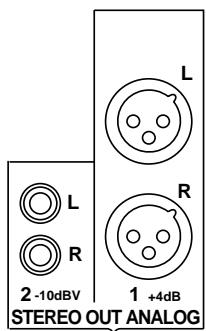
Analog Outputs
The 02R is equipped with a pair of analog stereo out connectors, one pair XLR-type for connecting to professional equipment, the other phono jacks. There are also two pairs of phone jacks to provide a stereo output to your control room and studio monitoring systems.
Monitor Selector Switches
STUDIO Buttons
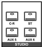
These buttons select the monitor signal sent to the studio monitor system. In many studios, this would be a headphone amplifier, typically one that could drive several sets of headphones. This system provides the monitoring that your musicians need in order to successfully work on a multitrack recording.
You can select the same signal that is being monitored in the control room with the [C-R] button. When you press this button, it cancels the current settings. When you press it again, it restores the previous settings.
You can send the signal from the stereo bus by pressing the [ST] button. The most flexible approach is to set up a separate mix using one of the auxiliary channels (press either the [AUX 5] or [AUX 6] button), and send that to the studio monitors. This allows you, for example, to apply reverb and equalization to the monitor signal you send to your vocalist, while you record the performance dry. You can select any combination of the [ST], [AUX 5], and [AUX 6] buttons—including none.
CONTROL ROOM Buttons
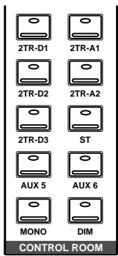
The buttons select the monitor signal sent to the control room monitor system. This is usually a large pair of near-field loudspeakers. Many studios also use a smaller speaker system, such as the YAMAHA NS-10M, to monitor a "typical" listening environment.
You can select one of five 2TR IN inputs, three of which are digital (the 2TR-D1 to 2TR-D3 buttons). These inputs are used for monitoring two track source signals, for example, the return of your master recorder. When you press any of these buttons, the current setting is cancelled. When you press the button again, the previous setting is restored.
You can also monitor the signal on the stereo bus with the [ST] button or select the auxiliary channels (AUX 5 or AUX 6). You can select any combination of the [ST], [AUX 5], and [AUX 6] buttons—including none.
Convert the monitor signal to monaural by pressing the [MONO] button or mute the output by 20 dB by pressing the [DIM] button.
SOLO Button

You can monitor input channels in isolation by pressing the [SOLO] button. The LEDs in the center of the selected channel [ON] buttons are extinguished. You select the channel(s) you want to solo by pressing the corresponding [ON] button. When you press the [SOLO] button again, the originally selected LEDs are illuminated again.
Note: If the 02R is connected to other units with the digital cascade kit (CD8-CS), only the [SOLO] button on the cascade master unit is valid. See "Digital Cascade Kit (CD8-CS)" on page 229 of the User's Guide
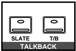
TALKBACK Buttons
The talkback system allows you to talk to musicians in the studio without leaving the 02R. Press the [T/B] button and start talking. The [SLATE] button sends the talkback signal to the main buses as well as the stereo bus, for example, allowing you to record a memo before recording a take.
You can also record 100Hz , 1kHz , and 10kHz sine waves and white noise tones by using the oscillator function. See "Oscillator" on page 209 of the User's Guide for details.
Monitor Level Controls

C-R LEVEL Control
This control is used to adjust the volume output through the control room monitor outputs.

T/B LEVEL Control
This control adjusts the volume of the talkback signal. The talkback signal is picked up by the built-in microphone right below the control.

STUDIO LEVEL Control
This control is used to adjust the overall volume output through the studio monitor outputs.
If you are using a headphone amplifier to provide studio monitoring, you may need a unit that allows individual adjustment of each set of headphones.

PHONES LEVEL Control
This control is used to adjust the volume of a set of stereo headphones plugged into the connector just above the control.
4
MIXING Display Functions
In this chapter...
Phase and Attenuation 32
Delay 34
Pan and Balance. 36
PanGang. 37
Stereo Width 37
PAN controls 38
Routing 39
ROUTING buttons. 40
Metering 41
View. 44
Channel Library. 48
EQ. 51
EQ controls 53
EQ Programs 54
EQ Library 55
Preset EQ Program Parameters 58
Phase and Attenuation
- Press the (Ø/ATT) button.

0/ATT
The / ATT page appears.
- Select a channel using the (SEL) buttons or the CURSOR buttons.
- To change the phase, press the (ENTER) button. The NOR icon changes to REV and is highlighted.
- To change the attenuation, rotate the encoder wheel until the desired value is shown.
- To set all channels (except the stereo output) to the same phase and attenuation, double-click the (ENTER) button.
Phase
The Phase function reverses the phase of an input signal by 180 degrees. The phase can be set for MIC/LINE inputs 1 to 24, TAPE inputs 1 to 16, and the effects return. Phase reversal can be used to compensate for incorrectly wired balanced cables and microphones. When a snare drum is miked top and bottom, the channel connected to the bottom microphone can be phase reversed to prevent phase cancellation.
NOR—normal phase
REV—reversed phase
The Phase functions of adjacent channels are not linked when those channels are configured as a stereo pair. Likewise, the Phase functions of odd and even channels 17 to 24 always work independently. The effects returns have only one phase control each, so the left and right signals of these channels are always controlled together. The stereo output does not have a phase reverse function. Phase can also be set on the View 1/2 page.
Attenuation
After A/D conversion, input signals can be attenuated using the Attenuation function. Signals can be attenuated from 0 dB to -96 dB in 1 dB steps. The stereo output can be attenuated from +12 dB to -96 dB. For the TAPE inputs, the Attenuation function comes after de-emphasis.
Attenuation can be used to compensate for level increases caused by EQ boosting or dynamics processing. Instead of using a GAIN control to reduce a boosted signal, it's better to use the Attenuation function. Although levels can be reduced using the GAIN controls, this also reduces the level of the signal being fed to the A/D converter, which is not desired. The Attenuation function comes after the A/D converter, so conversion performance is not affected.
The Attenuation functions of adjacent channels are not linked when those channels are configured as a stereo pair. Likewise, the Attenuation functions of odd and even channels 17 to 24 always work independently. The effects returns and stereo output channels have only one Attenuation control each, so the left and right signals of these channels are always controlled together.
Attenuation can also be set on the View 1/2 and EQ 1/2 pages. However, operation for input channels 17 to 24, and MIC or TAPE channels configured as stereo pairs is as follows: since only one attenuation control is displayed on the View or EQ page, the attenuation functions of each channel are linked to preserve their relative settings. If the channel whose control cannot be seen reaches the minimum or maximum attenuation setting, a message appears.
Phase & Attenuation Pages
There are two pages to the /ATT1/1 function. The first page, shown below, contains the Phase and Attenuation controls for MIC/LINE channels 1 to 24, and appears when one of these channels is selected.
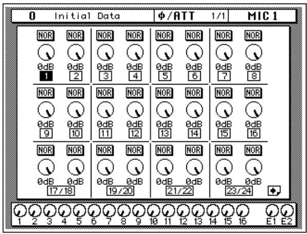
The second page, shown below, contains the Phase and Attenuation controls for TAPE channels 1 to 16, effects returns (EFF 1 and EFF 2), and the stereo output, and appears when one of these channels is selected.
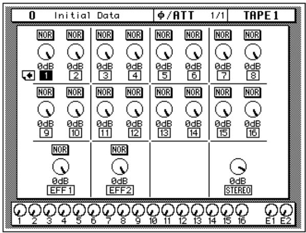
Note: When a stereo channel (17 to 24) is stored to the channel library, phase and attenuation parameters for both the left and right channels are stored. If such a channel program is recalled to a mono channel, the phase and attenuation settings of the left channel are used.
Delay
- Press the (DELAY) button.

DELAY
The DELAY display function appears.
- Select a channel using the (SEL) buttons or the CURSOR buttons.
- By default, the delay is off. Press the (ENTER) button to turn it on. The OFF icon, highlighted, changes to ON.
- Use the CURSOR buttons to select either ($mpl) or (mSEC).
- To change the delay, rotate the encoder wheel until the desired value is shown.
- To set all channels to the same delay time, double-click the (ENTER) button.
The DELAY display function is used to apply a small amount of delay to input or return signals to compensate for situations such as line or cabling delays or the gap between the record and playback heads (or circuitry) of your multitrack recorder. You can delay a signal from 0 to 2,600 samples—at 44.1kHz this is a delay of 0 to 59.0ms and at 48kHz it is a delay of 0 to 54.2ms .
Delay can be applied to any of the input channels and the tape and effect return channels. The stereo input channels are always ganged together. The MIC/LINE and TAPE channels are set independently only when they are not linked together in GANG mode with the PAN function
Delay and Cascade
If you use a digital cascade kit (CD8-CS) to connect more than four 02Rs together, you will need to use the DELAY display function to apply delay to the machines closest to the output. Set a delay value of 10 to 20 samples for each unit.
The digital cascade kit will automatically apply the correct amount of delay when you connect four or less 02Rs together. See "Cascade Configuration" on page 191 of the User's Guide.
Delay Pages
There are two pages to the DELAY 1/1 function. The first page, shown below, contains the Delay controls for MIC/LINE channels 1 to 24, and appears when one of these channels is selected.
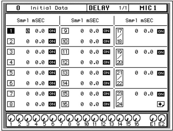
The second page, shown below, contains the Delay controls for TAPE channels 1 to 16 and effects returns (EFF 1 and EFF 2), and appears when one of these channels is selected.
Fine-Tuning the Delay
You can adjust the delay, either samples [Spl] or milliseconds [mSEC] with coarse or fine precision just by the placement of the cursor on the selected channel.
For example, if the cursor is positioned over the thousands digit of the samples [Spl] field, when you rotate the encoder wheel, the values increase or decrease by thousands of samples.
If the cursor is positioned over the hundreds or tens digit of the samples field, when you rotate the encoder wheel, the values increase or decrease by hundreds or tens of samples.
The same is true when the cursor is positioned over the ones digit of the samples field, or the tens, ones, or decimal digits of the milliseconds [mSEC] field.
Pan and Balance
- Press the (PAN) button.

PAN
The PAN display function appears.
- Select a channel using the (SEL) buttons or the CURSOR buttons.
- To change the pan position, rotate the encoder wheel until the desired value is shown.
The PAN display function is used to pan and balance signals. The input channels, including the stereo input channels, and the tape and effect returns can be panned, and the stereo output can be balanced.
Pan Pages
There are two pages to the PAN 1/1 function. The first page, shown below, contains the Pan controls for MIC/LINE channels 1 to 24, and appears when one of these channels is selected.
The second page, shown below, contains the Pan controls for TAPE channels 1 to 16, effects returns (EFF 1 and EFF 2), and the stereo output (balance), and appears when one of these channels is selected.
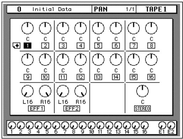
The number of the selected channel is highlighted. Channel pan positions are indicated by marker lines, just like the ones on real knobs. The current pan value is displayed under the panpot icon.
Note: When a stereo channel (17 to 24) is stored to the channel library, pan settings for both the left and right channels are stored. If such a channel program is recalled to a mono channel, the pan settings of the left channel are used.
Pan Positions
Including center, there are 33 pan positions:
$$ \mathrm {L} 1 6 \leftarrow \mathrm {L} 1 5 \leftarrow \dots \leftarrow \mathrm {L} 2 \leftarrow \mathrm {L} 1 \leftarrow \mathrm {C} \rightarrow \mathrm {R} 1 \rightarrow \mathrm {R} 2 \rightarrow \dots \rightarrow \mathrm {R} 1 5 \rightarrow \mathrm {R} 1 6 $$
Pan Gang
- Press the (PAN) button.

PAN
- Select a channel using the (SEL) buttons or the CURSOR buttons.
- Press the (ENTER) button to connect the odd and even channels together.
Pans can also be linked by pressing the PAN L/ODD and R/EVEN buttons at the same time.
When channels are configured as a stereo pair, pan controls remain independent. Using the Gang function pan controls of adjacent channels can be ganged together, indicated by dotted lines between the two controls, as shown below.
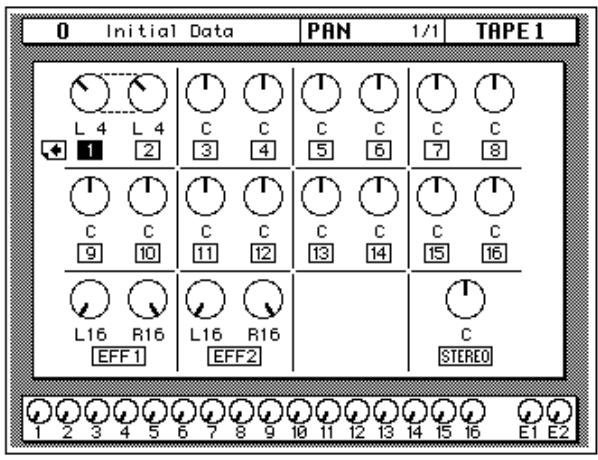
To cancel the Gang function, press the [ENTER] button again. The dotted lines between the pan controls disappear.
Stereo Width
When channels are configured as a stereo pair, the width of a stereo signal can be set using the pan controls. When the pan controls are set hard-left and hard-right, the stereo width is 100% . With both pans set to center the stereo width is 0% . Setting the controls to a position in between allows you to set the stereo width from 0% to 100% . To maintain a central balance, however, you must set both controls to a corresponding left and right values. For example, L5 and R5, or L10 and R10.
Switching to Gang mode allows you to reposition the stereo signal within the stereo field. For example, you could set L5 and R10 before you Gang the channels. After you press [ENTER], adjusting either channel moves the other a corresponding amount. If you set the left channel to L7, the right channel would adjust to R8.

PAN controls
You can also adjust the pan position or balance of the selected channel with the controls in the SELECTED CHANNEL group.
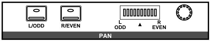
These controls allow you to select the pan position of the selected channel. The buttons select one of two channels (channels are always paired for the pan function). The LED is illuminated in the selected channel of the pair.
Use the rotary encoder to adjust the pan position. The current position is indicated on the adjacent LED bargraph.
You can link the odd and even channel pairs by pressing and holding the [L/ODD] button and then pressing the [R/EVEN] button. When a pair of channels are linked together in GANG mode, The LEDs in both buttons are illuminated and the LED of selected channel flashes. The indicator for the selected channel also flashes in the adjacent LED bargraph.
Note: You can customize your 02R so that when you adjust any of the controls in this group, the display switches to the PAN display function. See "Preferences" on page 198 of the User's Guide.
Routing
- Press the (ROUTING) button.

The ROUTING display function appears.
- Select a channel using the (SEL) buttons or the CURSOR buttons.
- Use the CURSOR buttons to select the routing destinations and press the (ENTER) button to switch a route ON or OFF.
The ROUTING display function is used to select the bus routing of the input channels and tape and effect return signals. The first 16 input channels, 1 through 16, can also be routed to the direct outputs. By default, all channels are routed to the stereo bus. Input channels configured as a stereo pair can be routed individually.
Note: Since routing a channel to its own input would create a feedback loop, the message "Would Cause Feedback!" appears if you attempt to route a channel to the bus selected as its input source on the SCENE 4/5 page. Also, if a channel library program containing routing settings that would cause such a feedback loop is recalled, the Input Patching settings on the SCENE 4/5 page are reset to their defaults.
Direct Outputs
All the input channels and tape and effect return signals can be routed to the output buses and the stereo bus. You can only route the first 16 input channels, MIC/LINE 1 through 16, to the direct outputs. The outputs for the optional boards are as follows:
| Slot | Direct Out all OFF | Direct Out all ON |
| Slot 1 | Bus 1 to 8 | Direct 1 to 8 |
| Slot 2 | Bus 1 to 8 | Direct 9 to 16 |
| Slot 3 | Bus 1 to 8 | Bus 1 to 8 |
| Slot 4 | Bus 1 to 8 | Bus 1 to 8 |
If you select both direct out and an output bus for a channel, the direct output will take priority.
Routing Pages
There are two pages to the ROUTING 1/2 function. The first page, shown below, contains the Routing controls for MIC/LINE channels 1 to 24, and appears when one of these channels is selected.
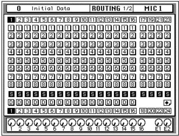
The second page, shown below, contains the Routing controls for TAPE channels 1 to 16 and effects returns (EFF 1 and EFF 2), and appears when one of these channels is selected.
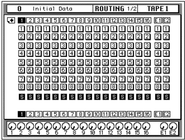
ROUTING buttons
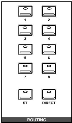
You can also set the routing for the selected channel with the ROUTING buttons in the SELECTED CHANNEL group. A route is selected ON when its icon is highlighted on the display.
The routing buttons allow you to directly select the destination for the selected channel. The LED in each the button illuminates to indicate the status of the channel.
Note: You can customize your 02R so that when you adjust any of the buttons in this group, the display switches to the ROUTING display function. See "Preferences" on page 198 of the User's Guide.
Metering
- Use the (METER) button to select the METER pages.

- Select a channel using the (SEL) buttons or the CURSOR buttons.
- Use the CURSOR buttons to select the PEAK HOLD icon and press the (ENTER) button to switch the function on or off.
- Select one of the meter source point icons—PRE EQ, POST EQ, or POST FADER—with the CURSOR buttons. Make it the current meter point by pressing the (ENTER) button.
The 02R features comprehensive signal level metering. The mono and stereo input channels, the tape and effect returns, and the auxiliary sends and buses are all metered using the METER display function. The control room output is metered using the dedicated 21-segment LED meters. Peak hold is available for all meters.
Meter Pages
There are three pages to the METER function. The first page, shown below, contains the meters for MIC/LINE channels 1 to 24, and appears when one of these channels is selected.

The second METER page, shown below, contains the meters for TAPE channels 1 to 16 and effects returns (EFF 1 and EFF 2), and appears when one of these channels is selected.
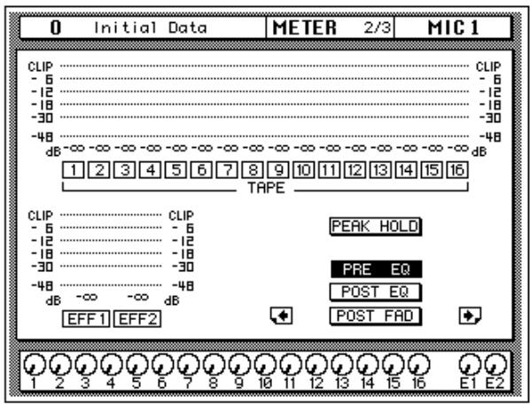
Setting the Bus Out and Aux Send Levels
- Use the CURSOR buttons to select one of the fader icons.
- Adjust the level by rotating the encoder wheel.
The third METER page contains the meters for the bus outs, aux sends, and the stereo output, plus the master faders for the bus outs and aux sends, and appears when one of these channels is selected.
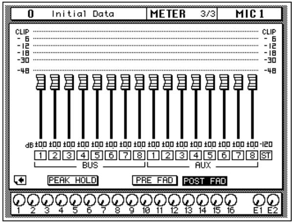
Peak Hold
The Peak Hold function can be turned on and off from any page of the METER display function. Clear the peak hold levels by turning the Peak Hold off (select the PEAK HOLD icon and press the [ENTER] button) or by selecting another display function. The dedicated control room output meter peak hold is not affected when other display functions are selected.
Note: When the 02R reaches CLIP, digital signal distortion occurs. You must ensure this does not happen. Digital distortion is very unpleasant sounding. There are several things you can do. If CLIP is reached, but the corresponding PEAK indicator is not illuminated, you need to attenuate the channel slightly with the / ATT display function (see "Phase and Attenuation" on page 32 of the User's Guide). Otherwise, back off the GAIN control a little (see "GAIN Controls" on page 27 of the User's Guide).
Meter Source Points
The following table lists the meter signal source points:
| Signal | Source Points | ||
| MIC/LINE 1-24 | Post GAIN and A/D, Pre EQ | Post EQ | Post Fader |
| TAPE 1-16, EFF1, EFF2 | Pre EQ | Post EQ | Post Fader |
| BUS 1-8, AUX 1-8, STE-REO OUT | Pre Fader | Post Fader | |
By changing the meter source points, you can easily observe the effect of changing the EQ or channel fader levels on the signal.
Note: Switching the meter source point for the input channels switches it for the tape and effect returns as well. Switching it for the tape and effect return changes the input channels.
Optional Meter Bridge—MB02
If your 02R is equipped with the optional Meter Bridge—MB02, the METER display function controls both the selection of the meter points for each channel as well as switching the Peak Hold function ON or OFF. The levels displayed on the optional meter bridge will be identical to the levels shown on the METER pages.
View
- Use the (VIEW) button to locate the VIEW 1/2 page.

- Select a channel by pressing one of the (SEL) buttons.
- Use the CURSOR buttons to select an item.
- Adjust the value of the item using the encoder wheel and/or the (ENTER) button.
- To set the EQ, use the CURSOR buttons to select the EQ curve and press the (ENTER) button. The 02R will switch to the EQ display function.
- To set the dynamics, select the dynamics curve with the CURSOR buttons and press the (ENTER) button. The 02R will switch to the DYNAMICS display function.
The VIEW display function allows you to see all the parameters of an individual channel at a glance and adjust any parameter that you feel requires a change. You can view the input channels (MIC/LINE 1 through 16, LINE 17/18 through 23/24) and the tape and effect return channels (TAPE 1 through 16, EFF1 and EFF2).
Shown below is the VIEW 1/2 page.
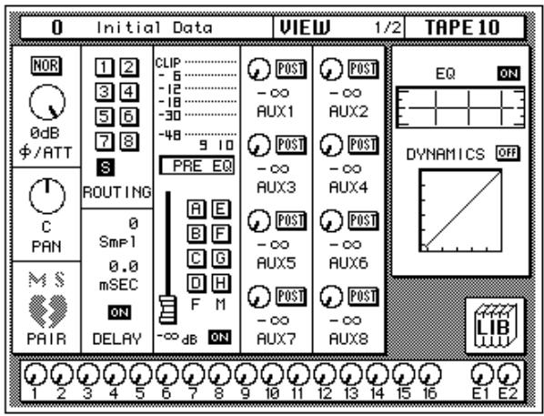
Unlike the previous display functions in this section, the VIEW display function shows the currently selected channel only.
Phase/Attenuation
Each time you press the [ENTER] button, the phase will alternate between NOR (normal) and REV (reversed). Rotate the encoder wheel to adjust the attenuation.
Operation for input channels 17 to 24, and MIC or TAPE channels configured as stereo pairs is as follows: since only one attenuation control is displayed on the View page, the attenuation functions of each channel are linked to preserve their relative settings. If the channel whose control cannot be seen reaches the minimum or maximum attenuation setting, a message appears. The indicators in the PAN [L/ODD] and [R/EVEN] buttons indicate whether the left or right channel of a pair is selected.
These controls duplicate the phase/attenuation function. See "Phase and Attenuation" on page 32 of the User's Guide.
Pan
Rotate the encoder wheel to set the pan position. You may find the PAN controls in the SELECTED CHANNEL group more convenient for setting the pan position.
When you press the [ENTER] button, the channel will be linked with its adjacent channel in GANG mode. Dotted lines will indicate the connection to the corresponding channel. Press the [ENTER] button again to switch back to INDIVIDUAL mode.
See "Pan and Balance" on page 36 and "Pan Gang" on page 37 of the User's Guide.
MS
The MS icon is used to turn the MS Decoding function on or off. When the MS function is turned on, channels are configured as a stereo pair automatically, and when the stereo pair is cancelled, the MS function is turned off. See page 186 for more information.
Pair
Each time you press the [ENTER] button, PAIR will alternately be set or cancelled. Pair only applies to the individual input and tape return channels. See "Pairing Channels" on page 184 of the User's Guide.
If the selected channel is one of the stereo input channels or the effect return channels, the PAIR function does not apply. Instead the pan icon for the opposite channel will be displayed here.
Routing
Use the CURSOR buttons to select the routing assignment. Each time you press the [ENTER] button, the selected route will alternately switch on or off. You may find using the ROUTING buttons in the SELECTED CHANNEL group a more convenient way to select the routes. See "Routing" on page 39 of the User's Guide.
Delay
Rotate the encoder wheel clockwise to increase the delay, counterclockwise to decrease the delay. You can select "Spl" (samples) or "mSEC" (milliseconds) with the CURSOR buttons. Press the [ENTER] button to turn the delay on or off. See "Delay" on page 34 of the User's Guide.
Note: The fine-tuning procedure is not available from this display function. See "Fine-Tuning the Delay" on page 35 of the User's Guide.
Meter Source Point
When the cursor is located at this part of the display, as you press the [ENTER] button, you can cycle through the meter source points—PRE EQ, POST EQ, or POST FADER. There are also level meters for the channel pair (selected and its corresponding even or odd mate). See "Metering" on page 41 of the User's Guide.
Groups and Channel ON
Use the CURSOR buttons to select the feder and mute group icons. Each time you press the [ENTER] button, the selected group will alternately be set or cancelled. Remember that a channel can only belong to one feder group and one mute group. See "Grouping Faders" on page 182 and "Grouping Mutes" on page 183 of the User's Guide.
Press the [ON] button to turn the channel on or off. See "ON Buttons" on page 28 of the User's Guide.
Beside the fader and mute group icons is the fader position icon. You cannot adjust this from the display, but it accurately reflects the current position of the channel fader. Displayed below the icon is the fader position in dB. See "Faders" on page 28 of the User's Guide.
Auxiliary Sends
Select an auxiliary channel with the CURSOR buttons. Each time you press the [ENTER] button, the setting alternates between pre and post-fader. To adjust the signal or to turn the send on or off, you need to use the AUX controls in the SELECTED CHANNEL group. The SEND LEVEL control adjusts the signal level and the [ON] button turns the send on or off. See "The AUX Buttons" on page 99 as well as "AUX 7 and AUX 8" on page 106 of the User's Guide.
EQ
When the cursor is on the ON icon, pressing the [ENTER] button will turn the EQ on or off. When the EQ is on, the icon text is "ON" and is highlighted.
Use the CURSOR buttons to select the EQ curve icon and press the [ENTER] button. The 02R will switch to the EQ display function. See "EQ" on page 51 of the User's Guide. To return to the VIEW display function, press the [VIEW] button again.
You may find using the EQUALIZER controls in the SELECTED CHANNEL group a more convenient way to set the equalization. See "EQ controls" on page 53 of the User's Guide.
Dynamics
When the cursor is on the OFF icon, pressing the [ENTER] button will turn the dynamics processor on or off. When the dynamics processor is off, the icon text is "OFF" and is displayed in normal video.
Use the CURSOR buttons to select the dynamics curve and press the [ENTER] button. The 02R will switch to the DYNAMICS display function. See "DYNAMICS Display Function" on page 83 of the User's Guide. To return to the VIEW display function, press the [VIEW] button again.
If the selected channel is one of the effect return channels, dynamics is replaced by the EFFECT TYPE display. It shows the name of the current effects program for the channel. Use the CURSOR buttons to select the effects program name and press the [ENTER] button. The 02R will switch to the EFFECT display function. See "Effects" on page 108 of the User's Guide. To return to the VIEW display function, press the [VIEW] button again.
Library
When the cursor is located on the LIB icon, press the [ENTER] button to access the channel library. You can also press the [VIEW] button again to achieve the same thing.
Channel Library
- Use the (VIEW) button to select the VIEW 2/2 page.

The Channel Library is used to access and store channel settings—stored as programs. There are 64 user programs (plus an UNDO buffer) for you to store your channel settings.
You can access the channel library from the VIEW 1/2 page by selecting the LIB icon with the CURSOR buttons and pressing the [ENTER] button.
Shown below is the VIEW 2/2 page.
Storing Channel Programs
- Select the STORE icon with the CURSOR button and use the encoder wheel to select a program number.
- Use the CURSOR buttons and encoder wheel to name the program.
- Press the (ENTER) button. The O2R pops up a confirmation request.
- Select EXECUTE and press the (ENTER) button. The channel program is stored.
Recalling Channel Programs
- Select the RECALL icon with the CURSOR buttons.
- Use the encoder wheel to select a channel program.
- Press the (ENTER) button. The channel program is recalled.
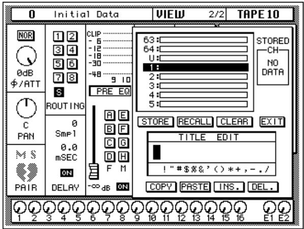
The Channel Library is overlaid on the VIEW 1/2 page.
The top of the display is a scrolling box containing the channel programs. The bottom of the display contains the icons and the TITLE EDIT box. Use the CURSOR buttons to select from the STORE, RECALL, CLEAR, COPY, PASTE, INS., DEL., and EXIT icons.
Selecting the EXIT icon and pressing the [ENTER] button switches back to the VIEW 1/2 page. You can also just press the [VIEW] button again.
Icons
- STORE—This icon is used to store the current program to the library. Select the icon with the CURSOR buttons. Use the encoder wheel to select a program and press the [ENTER] button. The 02R displays a confirmation dialog box asking if you want to store your settings in the selected program. The box has two icons: "CANCEL" and "EXECUTE".
Note: You can customize your 02R to prevent the confirmation dialog box appearing during the STORE operation. See “Preferences” on page 198 of the User's Guide for more information.
CANCEL is the default. To cancel the STORE operation, either press the [ENTER] button or wait about 10 seconds—the STORE operation will be automatically cancelled.
To store your settings, use the CURSOR buttons to select the "EXECUTE" icon and press the [ENTER] button. The program is stored.
When you confirm a STORE operation, any existing data in the selected program location will be overwritten.
YOU SHOULD ALWAYS BE CAREFUL WHEN THE 02R DISPLAYS A CONFIRMATION_DIALOG BOX!
- RECALL—This icon is used to recall a program from the library. Select the icon with the CURSOR buttons. Use the encoder wheel to select a program and press the [ENTER] button. The recalled program is now the current program.
- CLEAR—This icon is used to clear the contents of a channel program. Use the CURSOR buttons to select the icon. Use the encoder wheel to select a channel program and press the [ENTER] button. The 02R displays a confirmation dialog box asking you want to clear the channel program. The box has two icons: "CANCEL" and "EXECUTE".
Note: You can customize your 02R to prevent the confirmation dialog box appearing during the CLEAR operation. See "Preferences" on page 198 of the User's Guide for more information.
CANCEL is the default. To cancel the CLEAR operation, either press the [ENTER] button or wait about 10 seconds—the CLEAR operation will be automatically cancelled.
To clear the channel program, use the CURSOR buttons to select the "EXECUTE" icon and press the [ENTER] button. The program is cleared.
If you change your mind, the cleared channel program can be retrieved by recalling the Undo channel program (U).
- COPY—This icon is used to copy the name of a library program. Select the icon with the CURSOR buttons. Use the encoder wheel to select a program and press the [ENTER] button. The program name is copied into an edit buffer.
- PASTE—This icon is used to paste a program name previously selected with the COPY operation into the TITLE EDIT box. Select the icon with the CURSOR buttons and press the [ENTER] button. The program name is pasted from the edit buffer into the TITLE EDIT box for subsequent editing.
- INS.—This icon is used to insert blank characters into the TITLE EDIT box at the current cursor location. Select the icon with the CURSOR buttons and press the [ENTER] button.
- DEL.—This icon is used to delete characters from the TITLE EDIT box at the current cursor location. Select the icon with the CURSOR buttons and press the [ENTER] button.
UNDO Operation
When the 02R stores or recalls a program, the previous settings are always preserved in the UNDO buffer. If you discover you have made a mistake, you can always recall the UNDO buffer (displayed as "U:" in the scrolling list of programs). Use the CURSOR buttons to select the RECALL icon, then
rotate the encoder wheel until the UNDO buffer is the current program, and press the [ENTER] button. The previous settings are restored.
Program Name
Channel program names can be up to 16 characters long and can contain any of the following characters:
| ! | “ | # | $ | % | & | ' | ( | ) | * | + | , | - | . | / | |
| 0 | 1 | 2 | 3 | 4 | 5 | 6 | 7 | 8 | 9 | : | ; | < | = | > | ? |
| @ | A | B | C | D | E | F | G | H | I | J | K | L | M | N | O |
| P | Q | R | S | T | U | V | W | X | Y | Z | [ | \ | ] | ^ | _ |
| ` | a | b | c | d | e | f | g | h | i | j | k | I | m | n | o |
| p | q | r | s | t | u | v | w | x | y | z | { | | | } | ~ |
EQ
- Use the (EQ) button to select the EQ 1/2 page.

- Select a channel using the (SEL) buttons.
- Use the CURSOR buttons to select the EQ ON icon. Press the (ENTER) button to turn the EQ on or off.
The icon changes from ON to OFF. When the EQ is on, the icon is highlighted.
- Select a icon using the CURSOR buttons, for example the "F" control for the H-MID band.
- To change the value of the selected item, rotate the encoder wheel until the desired value is shown.
The 02R is equipped with a four-band, fully parametric EQ, with variable bandwidth, center frequency, gain, and ON/OFF parameters.
EQ can be applied to the input channels (MIC/LINE 1 through 16, LINE 17/18 through 23/24), the tape and effect return channels (TAPE 1 through 16, EFF1 and EFF2), and the stereo output. For stereo channels, the equalization curve is applied equally to both channels.
Shown below is the EQ 1/2 page.
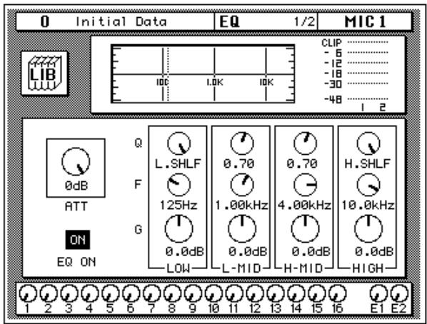
Similar to the VIEW display function, the EQ display function shows the equalization for the currently selected channel only.
The top of the display shows the EQ library icon, the equalization curve, and a level meter for the currently selected channel pair. The vertical dotted line in the equalization curve indicates the center frequency of the selected band.
The bottom of the display contains the icons for adjusting the parameters for the currently selected channel:
- ATT—The attenuator rotary icon is used to attenuate the channel level. Operation for input channels 17 to 24, and MIC or TAPE channels configured as stereo pairs is as follows: since only one attenuation control is displayed on the EQ page, the attenuation functions of each channel are linked to preserve their relative settings. If the channel whose control cannot be seen reaches the minimum or maximum attenuation setting, a message appears. The indicators in the PAN [L/ODD] and [R/EVEN] buttons indicate whether the left or right channel of a pair is selected.
This control duplicate Attenuation function. See "Phase and Attenuation" on page 32 of the User's Guide.
Note: The attenuator rotary icon is adjusting the same parameter as in the / ATT display function. When you boost the gain of the equalization curve, you may cause the overall signal level to reach CLIP. Watch the level meters for the selected pair as you adjust the EQ values. If CLIP is reached, digital signal distortion will occur.
- EQ ON icon—Indicates the status of the EQ, on or off. The text “ON” is highlighted when the EQ is on.
- Rotary icons—There is an icon for bandwidth (Q), center frequency (F), and gain (G) for each of the four bands, LOW, L-MID, H-MID, and HIGH.
Use the CURSOR buttons to select the desired icon and adjust its value with the rotary encoder. Switch the EQ on or off by pressing the [ENTER] button.
Equalization parameters:
| Q | F | G | |
| LOW/HPF | Peak 10 to 0.1 in 41 steps / SHELF / HPF | 21 Hz to 20.1 kHz in 1/12 octave steps *1 | ±18 dB in 0.5 dB steps HPF = ON/OFF |
| L-MID | Peak 10 to 0.1 in 41 steps | 21 Hz to 20.1 kHz in 1/12 octave steps *1 | ±18 dB in 0.5 dB steps |
| H-MID | Peak 10 to 0.1 in 41 steps | 21 Hz to 20.1 kHz in 1/12 octave steps *1 | ±18 dB in 0.5 dB steps |
| HIGH/LPF | Peak 10 to 0.1 in 41 steps / SHELF / LPF | 21 Hz to 20.1 kHz in 1/12 octave steps *1 | ±18 dB in 0.5 dB steps LPF = ON/OFF |
*1 When the sampling frequency is 32kHz , the frequency range (F) is 21Hz to 15.1kHz
EQ controls
You can also adjust the equalization for the selected channel with the EQUALIZER controls in the SELECTED CHANNEL group.
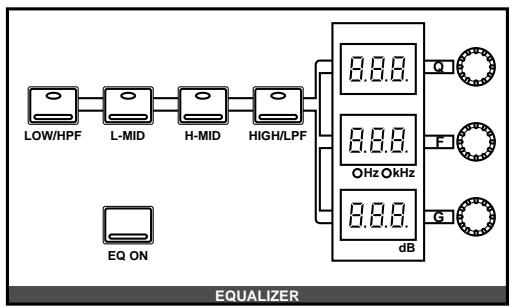
These controls allow you to adjust the equalization of the selected channel. Select the band you want to adjust with one the buttons in the top row: [LOW/HPF], [L-MID], [H-MID], or [HIGH/LPF]. The three LED indicators will reflect the status of the selected band. Adjust the values, Q (bandwidth), F (frequency), and G (gain), with the corresponding rotary encoders. Use the [EQ ON] button to insert the equalization into the channel.
Note: You can customize your 02R so that when you adjust any of the controls in this group, the display switches to the EQ display function. See “Preferences” on page 198 of the User's Guide.
Reset the Gain
You can reset the gain of each band to 0.0dB by double-clicking the corresponding [LOW/HPF], [L-MID], [H-MID], or [HIGH/LPF] buttons.
Reset the EQ
You can reset all the values of the EQ for the selected channel. Press and hold the [LOW/HPF] button and then press the [HIGH/LPF] button.
All the EQ values will be reset to their default.
| LOW/HPF | L-MID | H-MID | HIGH/LPF | |
| Q | LOW SHELF | Peak-0.7 | Peak-0.7 | HIGH SHELF |
| F | 125 Hz | 1.00 kHz | 4.00 kHz | 10.0 kHz |
| G | 0dB | 0dB | 0dB | 0dB |
EQ Programs
These are the preset EQ programs.
| No | Program Name | No | Program Name |
| 1 | Bass Drum 1 | 21 | A.G.Stroke 2 |
| 2 | Bass Drum 2 | 22 | A.G.Arpeggio 1 |
| 3 | Snare Drum 1 | 23 | A.G.Arpeggio 2 |
| 4 | Snare Drum 2 | 24 | Brass Section |
| 5 | Tom-tom 1 | 25 | Male Vocal 1 |
| 6 | Cymbal | 26 | Male Vocal 2 |
| 7 | High Hat | 27 | Female Vocal 1 |
| 8 | Percussion | 28 | Female Vocal 2 |
| 9 | E.Bass 1 | 29 | Chorus & Harmony |
| 10 | E.Bass 2 | 30 | Total EQ 1 |
| 11 | Syn.Bass 1 | 31 | Total EQ 2 |
| 12 | Syn.Bass 2 | 32 | Total EQ 3 |
| 13 | Piano 1 | 33 | Bass Drum 3 |
| 14 | Piano 2 | 34 | Snare Drum 3 |
| 15 | E.G.Clean | 35 | Tom-tom 2 |
| 16 | E.G.Crunch 1 | 36 | Piano 3 |
| 17 | E.G.Crunch 2 | 37 | Piano Low |
| 18 | E.G.Distortion 1 | 38 | Piano High |
| 19 | E.G.Distortion 2 | 39 | Fine-EQ(Cass) |
| 20 | A.G.Stroke 1 | 40 | Narrator |
Note: The programs 33 to 40 contain preset programs and are listed in the table above. However, you can store your own settings to these programs.
EQ Library
- Use the (EQ) button to select the EQ 2/2 page.

Recalling EQ Programs
The EQ Library is used to access and store EQ settings—stored as programs. There are 40 preset programs (1 to 40) for you to recall and 88 user programs (41 to 128 plus UNDO) for you to store your own EQ settings.
You can access the EQ library from the EQ 1/2 page by selecting the LIB icon with the CURSOR buttons and pressing the [ENTER] button.
Shown below is the EQ 2/2 page.
- Select a channel using the (SEL) buttons.
- Use the CURSOR buttons to select the RECALL icon and select an EQ program with the encoder wheel.
- Press the (ENTER) button. The EQ program is recalled.
Storing EQ Programs
- Use the CURSOR buttons to select the STORE icon and select an EQ program with the encoder wheel.
- Use the CURSOR buttons and encoder wheel to name the program.
- Press the (ENTER) button. The O2R pops up a confirmation request.
- Select EXECUTE and press the (ENTER) button. The EQ program is stored.
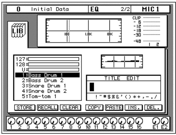
The top of the display shows the EQ library icon, the equalization curve, and a level meter for the currently selected channel pair.
The middle of the display shows a scrolling list of EQ programs. The name of the EQ program under the cursor is highlighted. The encoder wheel is used to scroll through the program list. A small diagram of the response curve of the highlighted EQ program is shown to the right.
Beside the list of EQ programs is the TITLE EDIT field. The CURSOR buttons are used to select the character, and the encoder wheel is used to change its value.
The bottom of the display contains the control button icons. Use the CURSOR buttons to select from the STORE, RECALL, CLEAR, COPY, PASTE, INS., and DEL. icons.
Exiting the Library
Selecting the LIB icon and pressing the [ENTER] button switches back to the EQ 1/1 page. You can also press the [EQ] button again.
Icons
- STORE—This icon is used to store the current program to the library. Select the icon with the CURSOR buttons. Use the encoder wheel to
select a program and press the [ENTER] button. The 02R displays a confirmation dialog box asking if you want to store your settings in the selected program. The box has two icons: "CANCEL" and "EXECUTE".
Note: You can customize your 02R to prevent the confirmation dialog box appearing during the STORE operation. See "Preferences" on page 198 of the User's Guide for more information.
CANCEL is the default. To cancel the STORE operation, either press the [ENTER] button or wait about 10 seconds—the STORE operation will be automatically cancelled.
To store your settings, use the CURSOR buttons to select the "EXECUTE" icon and press the [ENTER] button. The program is stored.
When you confirm a STORE operation, any existing data in the selected program location will be overwritten.
YOU SHOULD ALWAYS BE CAREFUL WHEN THE 02R DISPLAYS A CONFIRMATION DIALOG BOX!
- RECALL—This icon is used to recall a program from the library. Select the icon with the CURSOR buttons. Use the encoder wheel to select a program and press the [ENTER] button. The recalled program is now the current program.
- CLEAR—This icon is used to clear the contents of an EQ program. Use the CURSOR buttons to select the icon. Use the encoder wheel to select an EQ program and press the [ENTER] button. The 02R displays a confirmation dialog box asking if you want to clear the EQ program. The box has two icons: "CANCEL" and "EXECUTE".
Note: You can customize your 02R to prevent the confirmation dialog box appearing during the CLEAR operation. See “Preferences” on page 198 of the User's Guide for more information.
CANCEL is the default. To cancel the CLEAR operation, either press the [ENTER] button or wait about 10 seconds—the CLEAR operation will be automatically cancelled.
To clear the EQ program, use the CURSOR buttons to select the "EXECUTE" icon and press the [ENTER] button. The program is cleared.
If you change your mind, the cleared EQ program can be retrieved by recalling the Undo EQ program (U).
- COPY—This icon is used to copy the name of a library program. Select the icon with the CURSOR buttons. Use the encoder wheel to select a program and press the [ENTER] button. The program name is copied into an edit buffer.
-
PASTE—This icon is used to paste a program name previously selected with the COPY operation into the TITLE EDIT box. Select the icon with the CURSOR buttons and press the [ENTER] button. The program name is pasted from the edit buffer into the TITLE EDIT box for subsequent editing.
-
INS.—This icon is used to insert blank characters into the TITLE EDIT box at the current cursor location. Select the icon with the CURSOR buttons and press the [ENTER] button.
- DEL.—This icon is used to delete characters from the TITLE EDIT box at the current cursor location. Select the icon with the CURSOR buttons and press the [ENTER] button.
UNDO Operation
When the 02R stores or recalls a program, the previous settings are always preserved in the UNDO buffer. If you discover you have made a mistake, you can always recall the UNDO buffer (displayed as "U:" in the scrolling list of programs). Use the CURSOR buttons to select the RECALL icon, then rotate the encoder wheel until the UNDO buffer is the current program, and press the [ENTER] button. The previous settings are restored.
Program Name
EQ program names can be up to 16 characters long and can contain any of the following characters:
| ! | “ | # | $ | % | & | ' | ( | ) | * | + | , | - | . | / | |
| 0 | 1 | 2 | 3 | 4 | 5 | 6 | 7 | 8 | 9 | : | ; | < | = | > | ? |
| @ | A | B | C | D | E | F | G | H | I | J | K | L | M | N | O |
| P | Q | R | S | T | U | V | W | X | Y | Z | [ | \ | ] | ^ | _ |
| ` | a | b | c | d | e | f | g | h | i | j | k | l | m | n | o |
| p | q | r | s | t | u | v | w | x | y | z | { | | | } | ~ |
Preset EQ Program Parameters
| No | Name | Parameter | Description | ||||
| LOW | L-MID | H-MID | HIGH | ||||
| 1 | Bass Drum 1 | PEAKING | PEAKING | PEAKING | H.SHELF | Emphasizes the low range of the bass drum and the attack created by the beater. | |
| Q | 1.2 | 10 | 0.9 | ||||
| F | 99Hz | 265Hz | 1.05kHz | 5.33kHz | |||
| G | +3.5dB | -3.5dB | 0.0dB | +4.0dB | |||
| 2 | Bass Drum 2 | PEAKING | PEAKING | PEAKING | LPF | Creates a peak around 80Hz, producing a tight, stiff sound. | |
| Q | 1.4 | 4.5 | 2.2 | ||||
| F | 79Hz | 397Hz | 2.52kHz | 12.6kHz | |||
| G | +8.0dB | -7.0dB | +6.0dB | ON | |||
| 3 | Snare Drum 1 | PEAKING | PEAKING | PEAKING | H.SHELF | Emphasizes snapping and rimshot sounds. | |
| Q | 1.2 | 4.5 | 0.11 | ||||
| F | 132Hz | 1.00kHz | 3.17kHz | 5.04kHz | |||
| G | -0.5dB | 0.0dB | +3.0dB | +4.5dB | |||
| 4 | Snare Drum 2 | L.SHELF | PEAKING | PEAKING | PEAKING | Emphasizes the ranges of that classic rock snare drum sound. | |
| Q | 10 | 0.7 | 0.1 | ||||
| F | 177Hz | 334Hz | 2.37kHz | 4.00kHz | |||
| G | +1.5dB | -8.5dB | +2.5dB | +4.0dB | |||
| 5 | Tom-tom 1 | PEAKING | PEAKING | PEAKING | PEAKING | Emphasizes the attack of tom-toms, and creates a long, "leathery" decay. | |
| Q | 1.4 | 10 | 1.2 | 0.28 | |||
| F | 210Hz | 667Hz | 4.49kHz | 6.35kHz | |||
| G | +2.0dB | -7.5dB | +2.0dB | +1.0dB | |||
| 6 | Cymbal | L.SHELF | PEAKING | PEAKING | H.SHELF | Emphasizes the attack of crash cymbals, extending the "sparkling" decay. | |
| Q | 8 | 0.9 | |||||
| F | 105Hz | 420Hz | 1.05kHz | 13.4kHz | |||
| G | -2.0dB | 0.0dB | 0.0dB | +3.0dB | |||
| 7 | High Hat | L.SHELF | PEAKING | PEAKING | H.SHELF | Use on a tight high-hat, emphasizing the mid to high range. | |
| Q | 0.5 | 1 | |||||
| F | 94Hz | 420Hz | 2.82kHz | 7.55kHz | |||
| G | -4.0dB | -2.5dB | +1.0dB | +0.5dB | |||
| 8 | Percussion | L.SHELF | PEAKING | PEAKING | H.SHELF | Emphasizes the attack and clarifies the high-range of instruments, such as shakers, cabasas, and congas. | |
| Q | 4.5 | 0.56 | |||||
| F | 99Hz | 397Hz | 2.82kHz | 16.9kHz | |||
| G | -4.5dB | 0.0dB | +2.0dB | 0.0dB | |||
| 9 | E.Bass 1 | L.SHELF | PEAKING | PEAKING | H.SHELF | Makes a tight electric bass sound by cutting very low frequencies. | |
| Q | 5 | 4.5 | |||||
| F | 35Hz | 111Hz | 2.00kHz | 4.00kHz | |||
| G | -7.5dB | +4.5dB | +2.5dB | 0.0dB | |||
| 10 | E.Bass 2 | PEAKING | PEAKING | PEAKING | H.SHELF | Unlike program 9, this emphasizes the low range of the electric bass. | |
| Q | 0.1 | 5 | 6.3 | ||||
| F | 111Hz | 111Hz | 2.24kHz | 4.00kHz | |||
| G | +3.0dB | 0.0dB | +2.5dB | +0.5dB | |||
| 11 | Syn.Bass 1 | PEAKING | PEAKING | PEAKING | H.SHELF | Use on a synth bass with emphasized low range. | |
| Q | 0.1 | 8 | 4.5 | ||||
| F | 83Hz | 944Hz | 4.00kHz | 12.6kHz | |||
| G | +3.5dB | +8.5dB | 0.0dB | 0.0dB | |||
| 12 | Syn.Bass 2 | PEAKING | PEAKING | PEAKING | H.SHELF | Emphasizes the attack that is peculiar to a synth bass. | |
| Q | 1.6 | 8 | 2.2 | ||||
| F | 125Hz | 177Hz | 1.12kHz | 12.6kHz | |||
| G | +2.5dB | 0.0dB | +1.5dB | 0.0dB | |||
| 13 | Piano 1 | L.SHELF | PEAKING | PEAKING | H.SHELF | This is used to make a piano sound brighter. | |
| Q | 8 | 0.9 | |||||
| F | 94Hz | 944Hz | 3.17kHz | 7.55kHz | |||
| G | -6.0dB | 0.0dB | +2.0dB | +4.0dB | |||
| 14 | Piano 2 | PEAKING | PEAKING | PEAKING | H.SHELF | Emphasize the attack and low range of the piano sound by using a compressor. | |
| Q | 5.6 | 10 | 0.7 | ||||
| F | 223Hz | 595Hz | 3.17kHz | 5.33kHz | |||
| G | +3.5dB | -8.5dB | +1.5dB | +3.0dB | |||
| 15 | E.G.Clean | PEAKING | PEAKING | PEAKING | H.SHELF | Use for line-recording an electric guitar or semi-acoustic guitar to get a slightly hard sound. | |
| Q | 0.18 | 10 | 6.3 | ||||
| F | 265Hz | 397Hz | 1.33kHz | 4.49kHz | |||
| G | +2.0dB | -5.5dB | +0.5dB | +2.5dB | |||
| 16 | E.G.Crunch 1 | PEAKING | PEAKING | PEAKING | PEAKING | Adjusts the tonal quality of a slightly distorted guitar sound. | |
| Q | 8 | 4.5 | 0.63 | 9 | |||
| F | 140Hz | 1.00kHz | 1.88kHz | 5.65kHz | |||
| G | +4.5dB | 0.0dB | +4.0dB | +2.0dB | |||
| 17 | E.G.Crunch 2 | PEAKING | PEAKING | PEAKING | H.SHELF | This is a variation on program 16. | |
| Q | 8 | 0.4 | 0.16 | ||||
| F | 125Hz | 445Hz | 3.36kHz | 19.0kHz | |||
| G | +2.5dB | +1.5dB | +2.5dB | 0.0dB | |||
| 18 | E.G.Distortion 1 | L.SHELF | PEAKING | PEAKING | H.SHELF | Makes a heavily distorted guitar sound clearer. | |
| Q | 9 | 10 | |||||
| F | 354Hz | 944Hz | 3.36kHz | 12.6kHz | |||
| G | +5.0dB | 0.0dB | +3.5dB | 0.0dB | |||
| 19 | E.G.Distortion 2 | L.SHELF | PEAKING | PEAKING | H.SHELF | This is a variation on program 18. | |
| Q | 10 | 4 | |||||
| F | 315Hz | 1.05kHz | 4.23kHz | 12.6kHz | |||
| G | +6.0dB | -8.5dB | +4.5dB | +4.0dB | |||
| 20 | A.G.Stroke 1 | PEAKING | PEAKING | PEAKING | H.SHELF | Emphasizes the bright tones of an acoustic guitar. | |
| Q | 0.9 | 4.5 | 3.5 | ||||
| F | 105Hz | 1.00kHz | 1.88kHz | 5.33kHz | |||
| G | -2.0dB | 0.0dB | +1.0dB | +4.0dB | |||
| 21 | A.G.Stroke 2 | L.SHELF | PEAKING | PEAKING | H.SHELF | This is a variation on program 20. You can also use it for the electric gut guitar. | |
| Q | 9 | 4.5 | |||||
| F | 297Hz | 749Hz | 2.00kHz | 3.56kHz | |||
| G | -3.5dB | -2.0dB | 0.0dB | +2.0dB | |||
| 22 | A.G.Arpeggi 1 | L.SHELF | PEAKING | PEAKING | PEAKING | Corrects arpeggio technique of an acoustic guitar. | |
| Q | 4.5 | 4.5 | 0.12 | ||||
| F | 223Hz | 1.00kHz | 4.00kHz | 6.72kHz | |||
| G | -0.5dB | 0.0dB | 0.0dB | +2.0dB | |||
| 23 | A.G.Arpeggi 2 | L.SHELF | PEAKING | PEAKING | H.SHELF | This is a variation on program 22. | |
| Q | 7 | 4.5 | |||||
| F | 177Hz | 354Hz | 4.00kHz | 4.23kHz | |||
| G | 0.0dB | -5.5dB | 0.0dB | +4.0dB | |||
| 24 | Brass Section | PEAKING | PEAKING | PEAKING | PEAKING | Use with trumpets, trombones, or sax. With one instrument, adjust the HIGH or H-MID frequency. | |
| Q | 2.8 | 2 | 0.7 | 7 | |||
| F | 88Hz | 841Hz | 2.11kHz | 4.49kHz | |||
| G | -2.0dB | +1.0dB | +1.5dB | +3.0dB | |||
| 25 | Male Vocal 1 | PEAKING | PEAKING | PEAKING | PEAKING | Use as a template for male vocal. Adjust the HIGH or H-MID setting according to the voice quality. | |
| Q | 0.11 | 4.5 | 0.56 | 0.11 | |||
| F | 187Hz | 1.00kHz | 2.00kHz | 6.72kHz | |||
| G | -0.5dB | 0.0dB | +2.0dB | +3.5dB | |||
| 26 | Male Vocal 2 | PEAKING | PEAKING | PEAKING | H.SHELF | This is a variation on program 25. | |
| Q | 0.11 | 10 | 5.6 | ||||
| F | 167Hz | 236Hz | 2.67kHz | 6.72kHz | |||
| G | +2.0dB | -5.0dB | +2.5dB | +4.0dB | |||
| 27 | Female Vocal 1 | PEAKING | PEAKING | PEAKING | PEAKING | Use as a template for female vocal. Adjust the HIGH or H-MID setting according to the voice quality. | |
| Q | 0.18 | 0.45 | 0.56 | 0.14 | |||
| F | 118Hz | 397Hz | 2.67kHz | 5.99kHz | |||
| G | -1.0dB | +1.0dB | +1.5dB | +2.0dB | |||
| 28 | Female Vocal 2 | L.SHELF | PEAKING | PEAKING | H.SHELF | This is a variation on program 27 | |
| Q | 0.16 | 0.2 | |||||
| F | 111Hz | 334Hz | 2.00kHz | 6.72kHz | |||
| G | -7.0dB | +1.5dB | +1.5dB | +2.5dB | |||
| 29 | Chorus & Harmony | PEAKING | PEAKING | PEAKING | PEAKING | Use as a template for a chorus. It makes the entire chorus much brighter. | |
| Q | 2.8 | 2 | 0.7 | 7 | |||
| F | 88Hz | 841Hz | 2.11kHz | 4.49kHz | |||
| G | -2.0dB | +1.0dB | +1.5dB | +3.0dB | |||
| 30 | Total EQ 1 | PEAKING | PEAKING | PEAKING | H.SHELF | Use on the STEREO bus during mixdown. For more effect, try it with a compressor. | |
| Q | 7 | 2.2 | 5.6 | ||||
| F | 94Hz | 944Hz | 2.11kHz | 16.0kHz | |||
| G | -0.5dB | 0.0dB | +3.0dB | +6.5dB | |||
| 31 | Total EQ 2 | PEAKING | PEAKING | PEAKING | H.SHELF | This is a variation on program 30. | |
| Q | 7 | 2.8 | 5.6 | ||||
| F | 94Hz | 749Hz | 1.78kHz | 17.9kHz | |||
| G | +4.0dB | +1.5dB | +2.0dB | +6.0dB | |||
| 32 | Total EQ 3 | L.SHELF | PEAKING | PEAKING | H.SHELF | This is a variation on program 30. Also use these programs for stereo inputs or external effect returns. | |
| Q | 0.28 | 0.7 | |||||
| F | 66Hz | 841Hz | 1.88kHz | 15.1kHz | |||
| G | +1.5dB | +0.5dB | +2.0dB | +4.0dB | |||
| 33 | Bass Drum 3 | PEAKING | PEAKING | PEAKING | PEAKING | This is a variation on program 1. The low and mid range is removed. | |
| Q | 2 | 10 | 0.4 | 0.4 | |||
| F | 118Hz | 315Hz | 4.23kHz | 20.1kHz | |||
| G | +3.5dB | -10.0dB | +3.5dB | 0.0dB | |||
| 34 | Snare Drum 3 | L.SHELF | PEAKING | PEAKING | PEAKING | This is a variation on program 3. It creates rather thick sound. | |
| Q | 4.5 | 2.8 | 0.1 | ||||
| F | 223Hz | 561Hz | 4.23kHz | 4.00kHz | |||
| G | 0.0dB | +2.0dB | +3.5dB | 0.0dB | |||
| 35 | Tom-tom 2 | L.SHELF | PEAKING | PEAKING | H.SHELF | This is a variation on program 5. Emphasizes the mid and high range. | |
| Q | 4.5 | 1.2 | |||||
| F | 88Hz | 210Hz | 5.33kHz | 16.9kHz | |||
| G | -9.0dB | +1.5dB | +2.0dB | 0.0dB | |||
| 36 | Piano 3 | PEAKING | PEAKING | PEAKING | H.SHELF | This is a variation on program 13. | |
| Q | 8 | 10 | 9 | ||||
| F | 99Hz | 472Hz | 2.37kHz | 10.0kHz | |||
| G | +4.5dB | -13.0dB | +4.5dB | +2.5dB | |||
| 37 | Piano Low | PEAKING | PEAKING | PEAKING | H.SHELF | Use for the low range of the piano sound when it is recorded in stereo. Use with program 38. | |
| Q | 10 | 6.3 | 2.2 | ||||
| F | 187Hz | 397Hz | 6.72kHz | 12.6kHz | |||
| G | -5.5dB | +1.5dB | +6.0dB | 0.0dB | |||
| 38 | Piano High | PEAKING | PEAKING | PEAKING | PEAKING | Use for the high range of the piano sound when it is recorded in stereo. Use with program 37. | |
| Q | 10 | 6.3 | 2.2 | 0.1 | |||
| F | 187Hz | 397Hz | 6.72kHz | 5.65kHz | |||
| G | -5.5dB | +1.5dB | +5.0dB | +3.0dB | |||
| 39 | Fine-EQ(Cass) | L.SHELF | PEAKING | PEAKING | H.SHELF | Use for recording to or from cassette tape to make the sound clearer. | |
| Q | 4.5 | 1.8 | |||||
| F | 74Hz | 1.00kHz | 4.00kHz | 12.6kHz | |||
| G | -1.5dB | 0.0dB | +1.0dB | +3.0dB | |||
| 40 | Narrator | PEAKING | PEAKING | PEAKING | H.SHELF | Use for recording a voice reading a text. | |
| Q | 4 | 7 | 0.63 | ||||
| F | 105Hz | 707Hz | 2.52kHz | 10.0kHz | |||
| G | -4.0dB | -1.0dB | +2.0dB | 0.0dB | |||
Note: The EQ programs were programmed for recording acoustic musical instruments. If you are using them for a sampler, synthesizer, or rhythm machine, adjust the parameters accordingly.
Note: Programs 33 to 40 contain preset programs and are listed in the table above. However, you can store your own settings to these programs.
5
Surround Pan
In this chapter...
About Surround Pan. 64
Selecting a Surround Mode 65
Panning Sounds Freely 67
Panning Sounds Using the Trajectories 69
Linking Channels for Surround Pan. 72
CSR (Center:Side Ratio) 73
About Surround Pan
The 02R Surround Pan function supports 2 + 2,3 + 1, and 3 + 2 + 1 surround modes, making it ideal for sophisticated surround sound production. Sounds can be moved freely around a two-dimensional sound space, or along preset circle, ellipse, semicircle, or diagonal trajectories. Surround channels can be transferred directly to a digital multitrack recorder via YGDAI (DIGITAL I/O 5/5). In addition, surround channels can be output via the analog aux sends (SETUP 2/4).
Output Assignments
The following table shows how the surround channels are assigned to the 02R bus outs in each mode. Connect the bus outs that correspond to the mode you are using to a surround sound monitoring system or recorder. Use the DIGITAL I/O 5/5 page to set the bus out to I/O card assignments. See "Slot Output Select" on page 194.
| Mode | BUS 1 | BUS 2 | BUS 3 | BUS 4 | BUS 5 | BUS 6 |
| 2+2 | FL(front left) | FR(front right) | RL(rear left) | RR(rear right) | — | — |
| 3+1 | L(left) | R(right) | C(center) | S(surround) | — | — |
| 3+2+1 | FL(front left) | FR(front right) | RL(rear left) | RR(rear right) | FC(front center) | SW(subwoofer) |
While a surround mode is active, buses 1 to 6 cannot be used for regular routing. Buses 5 and 6, however, can be used as normal with the 2 + 2 and 3 + 1 surround modes.
Selecting a Surround Mode
- Use the (ROUTING) button to locate the ROUTING 2/4 page.

ROUTING
- Use the CURSOR buttons to select the SURROUND icon, and press the (ENTER) button.
A confirmation dialog box appears.
- Select EXECUTE and press the (ENTER) button.
- Use the CURSOR buttons to select a surround mode, and press the (ENTER) button.
- To turn off the Surround function, select the SURROUND icon and press the (ENTER) button.
Surround pan modes are selected on the ROUTING 2/2 page—Surround On/Off. When the Surround function is active, there are four ROUTING pages.
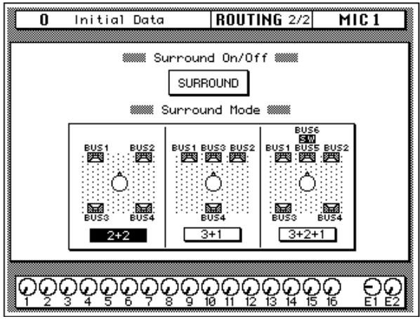
2+2 Surround Mode
Four-channel surround sound consisting of front left (FL), front right (FR), rear left (RL), and rear right (RR) channels.
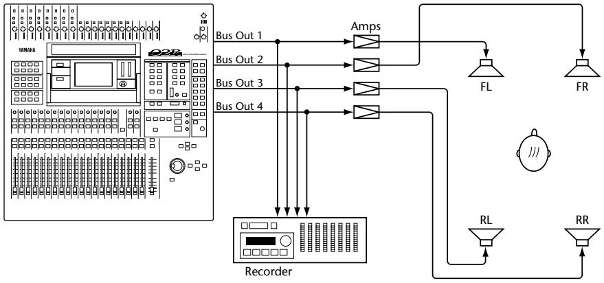
3+1 Surround Mode
Four-channel surround sound consisting of left (L), center (C), right (R), and surround (S) channels. Ideal for Dolby Surround authoring.
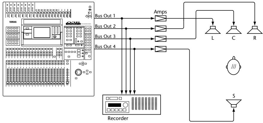
3+2+1 Surround Mode
Six-channel surround sound consisting of front left (FL), front center (FC), front right (FR), rear left (RL), rear right (RR), and subwoofer (SW) channels. Ideal for Dolby AC-3 Surround authoring.
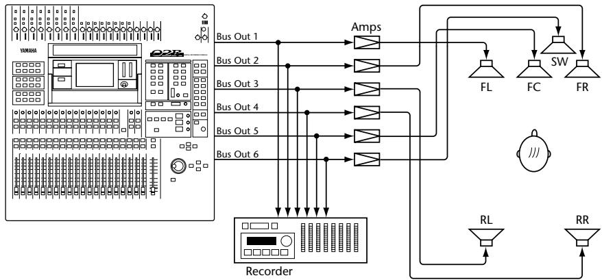
Panning Sounds Freely
- Use the (ROUTING) button to locate the ROUTING 3/4 page.

ROUTING
- Use the CURSOR buttons to select the MIC, LINE, or TAPE icon, and press the (ENTER) button.
- Use the (SEL) buttons to select a channel.
- Use the CURSOR buttons to select the left/right or front/rear parameter.
- Use the encoder wheel to position the sound.
This section explains how to position sounds using the ROUTING 3/4 page. Sounds can also be moved along preset circle, ellipse, semicircle, or diagonal trajectories on the ROUTING 4/4 page.
The ROUTING 3/4 page consists of three parts: MIC, LINE, and TAPE, and the three icons at the top of the page are used to select them. These pages are selected automatically when the relevant [SEL] button is pressed. All pages feature the timecode counter. The MIC page, shown below, contains surround pan controls for MIC inputs 1 to 16.
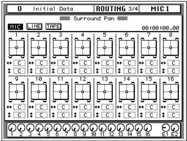
The surround pan position for each channel is displayed on a two-dimensional pan graph. The pan position is indicated by a small circle. Small speaker icons above and below the pan graph indicate the selected surround pan mode. In this example, two speakers at the front and two at the rear indicate that 2 + 2 surround mode is selected. Below the pan graph are two parameters. The 艹 left/right) parameter moves the sound from left to right. The front/rear) parameter moves the sound from front to rear.
The LINE page, shown below, contains surround pan controls for LINE inputs 17 to 24 and the effects returns.
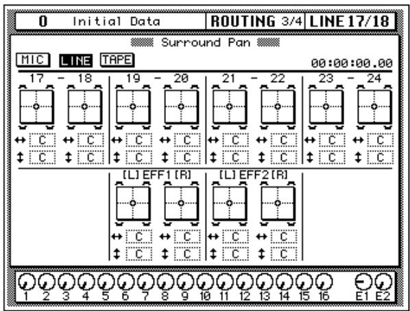
The TAPE page, shown below, contains surround pan controls for TAPE inputs 1 to 16.
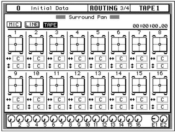
Panning Sounds Using the Trajectories
- Use the (ROUTING) button to locate the ROUTING 4/4 page.

ROUTING
This page can also be accessed from the ROUTING 3/4 page by pressing the (ENTER) button while a surround pan graph is selected.
- Use the (SEL) buttons to select a channel.
- Use the CURSOR buttons to select a trajectory, and press the (ENTER) button to activate it.
- Set the Width, Depth, and Offset parameters using the encoder wheel.
- Move the cursor to another parameter and use the encoder wheel to move the sound along the selected trajectory.
When the FAST icon is highlighted, sounds can be moved at high speed.
- To return to the ROUTING 3/4 page, select the EXIT icon and press the (ENTER) button.
This section explains how to move sounds along preset circle, ellipse, semicircle, or diagonal trajectories using the ROUTING 4/4 page. The preset trajectories can be fine-tuned using the Width, Depth, and Offset parameters.
The ROUTING 4/4 page, shown below, can be located using either the [ROUTING] button or by pressing the [ENTER] button while a surround pan graph on the ROUTING 3/4 page is selected. The EXIT icon on the ROUTING 4/4 page can be used to return to the ROUTING 3/4 page. Like the ROUTING 3/4 pages, the ROUTING 4/4 page features a timecode counter.
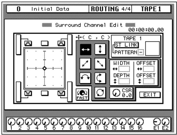
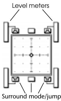
The surround pan position for each channel is displayed on a two-dimensional pan graph. The pan position is indicated by a small circle. Small speaker icons above and below the pan graph indicate the selected surround pan mode. In this example, two speakers at the front and two at the rear indicate that 2 + 2 surround mode is selected. Next to each speaker is a signal level meter indicating the master bus out level. Selecting a speaker icon and then pressing the [ENTER] button makes the sound jump to that speaker. In 3 + 2 + 1 mode, a subwoofer level control is available on this page.
To quickly move a sound to the default position, select the left/right trajectory icon and double-click the [ENTER] button.
Trajectories
The following surround pan trajectories are available.

Left to right—The sound moves from left to right. The following illustrations show some typical left to right trajectories.
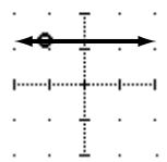

Front to rear—The sound moves from front to back. The following illustrations show some typical front to rear trajectories.
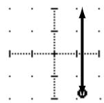

Rear left to front right diagonal—The sound moves on a diagonal trajectory from the rear left to the front right. Width, depth and offset can be set for this trajectory. The following illustrations show some typical trajectories.
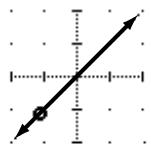
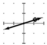
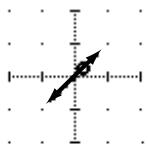

Front left to rear right diagonal—The sound moves on a diagonal trajectory from the front left to the rear right. Width, depth and offset can be set for this trajectory. The following illustrations show some typical trajectories.
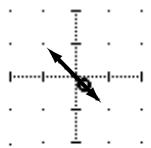

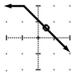

Left to right semicircle—The sound moves from left to right on a semicircular trajectory. Use the width and depth parameters to set the size and shape of the semicircle. The shape can be adjusted from a semicircle to a narrow oval. Use the offset parameters to offset the trajectory to the left, right, front, or rear. The following illustrations show some typical trajectories.
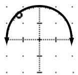
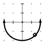

Front to rear semicircle—The sound moves from front to rear on a semicircular trajectory. Use the width and depth parameters to set the size and shape of the semicircle. The shape can be adjusted from a semicircle to a narrow oval. Use the offset parameters to offset the trajectory to the left, right, front, or rear. The following illustrations show some typical trajectories.
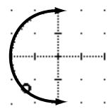
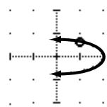
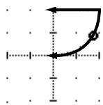
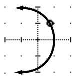

Circle—The sound moves on a circular trajectory. Use the width and depth parameters to set the size and shape. The shape can be adjusted from a perfect circle to a narrow oval. Use the offset parameters to offset the trajectory to the left, right, front, or rear. The following illustrations show some typical trajectories.
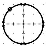
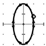
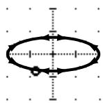
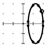
Linking Channels for Surround Pan
- Use the (ROUTING) button to locate the ROUTING 4/4 page.

ROUTING
- Use the (SEL) buttons to select a channel.
- Use the CURSOR buttons to select the ST LINK icon, and then press the (ENTER) button.
- Use the CURSOR buttons to select the PATTERN parameter, and the encoder wheel to select a pattern.
For stereo input channels (17 to 24), or mono input channels configured as a stereo pair, you can select one of eight patterns and move both sounds together. The following illustration shows how the two channels are panned with the various patterns and trajectories.
| Trajectory Pattern | ← | ↑ | |||||
| ←→ | ←→ | ||||||
| ←→ | ↑ | × | × | ||||
| → | × | × | |||||
| → | |||||||
| ← | |||||||
| ←→ | |||||||
| ←→ | ↑ | ||||||
| ←→ | |||||||
| ←→ |
Note: ST LINK settings are not stored in channel library programs. So when a channel program is recalled and the destination channel is using ST LINK, the surround settings of the other linked channel are changed to match. Also, when the surround settings of a stereo channel are stored, only the settings of the selected channel are stored.
By default, ST LINK is turned on for stereo channels. Note that if just the ST LINK parameter is turned off, it is possible to overwrite the pan movements of the other channel during subsequent automix recording.
CSR (Center:Side Ratio)
- Use the (ROUTING) button to locate the ROUTING 4/4 page.

ROUTING
- Use the (CURSOR) buttons to select the CSR control.
- Use the encoder wheel to set the CSR ratio.
For the 3 + 1 and 3 + 2 + 1 surround modes that use a center speaker, the CSR (Center:Side Ratio) control can be used to set the amount of front-center sound heard through the center and left and right front speakers.
| CSR | Description |
| 0.0 | The front-center sound appears only in the left and right speakers. |
| 0.5 | The front-center sound appears in the center and left and right speakers at the same level. |
| 1.0 | The front-center sound appears only in the center speaker. |
Surround Pan Notes
Surround pan settings can be stored and recalled using scene memories. The FAST parameter setting on the ROUTING 4/4 page, however, is not stored.
Real-time surround pan adjustments can be recorded in an automix, and on the SETUP 4/4 page—Preferences 2—you can choose which surround parameters are recorded: X/Y (surround pan position), CSR (Center:Side ratio), and SWF (subwoofer).
Although it is possible to select other trajectories on the ROUTING 4/4 page while automix recording is in progress, these actions are not recorded. Likewise, the ST LINK parameter cannot be turned on or off while recording. In both cases an "Automix Running" message appears. To automate these parameters, store the settings in a scene memory and use the automix to recall that.
When channels are linked using ST LINK, the X/Y pan movements of both channels are recorded regardless of which channel is selected. CSR and subwoofer adjustments, however, are recorded only for the selected channel. Of course, if the channels are configured as a stereo pair, CSR and subwoofer adjustments of both channels are recorded.
The X/Y pan movements of left and right channels in a stereo pair cannot be recorded individually. Note that if the ST LINK parameter is turned off after X/Y pan movements have been recorded, it is possible to overwrite the X/Y pan movements of the other channel during subsequent automix recording.
#
Dynamics
In this chapter...
Dynamics Processors. 76
PresetDynamicsPrograms 76
Compressor. 77
Expander. 79
Compander. 80
Gate and Ducking 81
DYNAMICS Display Function 83
Patching in a Processor 84
Dynamics Processor Meters 85
KEY IN and LINK Indicators. 86
Dynamics Library 87
PresetDynamicsProgramParameters. 90
Dynamics Processors
Dynamics processors are generally used to correct or control signal levels. However, you can also use them creatively to shape the volume envelope of a sound. The 02R features comprehensive dynamics processors for all the input channels, tape returns, and the bus and stereo outputs. These processors allow you to compress, expand, compress-expand (compand), gate, or duck the signals passing through the mixer, giving you unparalleled sonic quality and flexibility.
Preset Dynamics Programs
These are the preset dynamics programs.
| No | Program Name | No | Program Name | ||
| 1 | A.Dr.BD | "CMP | 21 | BrassSection | "CMP |
| 2 | A.Dr.BD | "EXP | 22 | Syn.Pad | "CMP |
| 3 | A.Dr.BD | "GAT | 23 | SamplingPerc | "CPS |
| 4 | A.Dr.BD | "CPH | 24 | Sampling BD | "CMP |
| 5 | A.Dr.SN | "CMP | 25 | Sampling SN | "CMP |
| 6 | A.Dr.SN | "EXP | 26 | Hip Comp | "CPS |
| 7 | A.Dr.SN | "GAT | 27 | Solo Vocal1 | "CMP |
| 8 | A.Dr.SN | "CPS | 28 | Solo Vocal2 | "CMP |
| 9 | A.Dr.Tom | "EXP | 29 | Chorus | "CMP |
| 10 | A.Dr.OverTop | "CPS | 30 | Compander(H) | "CPH |
| 11 | E.B.finger | "CMP | 31 | Compander(S) | "CPS |
| 12 | E.B.slap | "CMP | 32 | Click Erase | "EXP |
| 13 | Syn.Bass | "CMP | 33 | Announcer | "CPH |
| 14 | Piano1 | "CMP | 34 | Easy Gate | "GAT |
| 15 | Piano2 | "CMP | 35 | BGM Ducking | "DUK |
| 16 | E.Guitar | "CMP | 36 | Limiter1 | "CPS |
| 17 | A.Guitar | "CMP | 37 | Limiter2 | "CMP |
| 18 | Strings1 | "CMP | 38 | Total Comp1 | "CMP |
| 19 | Strings2 | "CMP | 39 | Total Comp2 | "CMP |
| 20 | Strings3 | "CMP | 40 | Total Comp3 | "CMP |
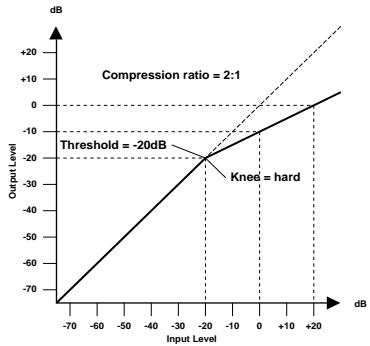
Compressor
A compressor provides a form of automatic level control. By attenuating high levels, thus effectively reducing the dynamic range, the compressor makes it much easier to control signals and set appropriate fader levels. Reducing the dynamic range also means that recording levels can be set higher, therefore improving the signal-to-noise performance.
Compressor (CMP) parameters:
| Parameter | Value | |
| Threshold (dB) | -54 to 0 | (55 points) |
| Ratio | 1.0, 1.1, 1.3, 1.5, 1.7, 2.0, 2.5, 3.0, 3.5, 4.0, 5.0, 6.0, 8.0, 10, 20, ∞ | (16 points) |
| Attack (ms) | 0 to 120 | (121 points) |
| Outgain (dB) | 0 to +18 | (36 points) |
| Knee | hard,1,2,3,4,5 | (6 points) |
| Release (ms) | 5 ms to 42.3 sec *1, 6 ms to 46.0 sec *2, 8 ms to 63.4 sec *3 | (160 points) |
1 These values are obtained when the sampling frequency is 48kHz
2 These values are obtained when the sampling frequency is 44.1kHz .
*3 These values are obtained when the sampling frequency is 32kHz
Threshold determines the level of input signal required to trigger the compressor. Signals at a level below the threshold pass through unaffected. Signals at and above the threshold level are compressed by the amount specified using the Ratio parameter. The trigger signal is determined using the KEY IN parameter.
Note: See "KEY IN" on page 84 of the User's Guide for an explanation of the KEY IN parameter.
Ratio controls the amount of compression—the change in output signal level relative to change in input signal level. With a 2:1 ratio, for example, a 10 dB change in input level (above the threshold) results in a 5 dB change in output level. For a 5:1 ratio, a 10 dB change in input level (above the threshold) results in a 2 dB change in output level.
Attack controls how soon the signal is compressed once the compressor has been triggered. With a fast attack time, the signal is compressed almost immediately. With a slow attack time, the initial transient of a sound passes through unaffected.
Out Gain sets the compressor's output signal level. Compression tends to reduce the average signal level. Out Gain can be used to counter this level reduction and set an appropriate level for the next stage in the audio path.
Knee sets the transition of the signal at the threshold. With a hard knee, the transition between uncompressed and compressed signal is immediate. With the softest knee, knee5, the transition starts before the signal reaches the threshold and gradually ends above the threshold.
Release determines how soon the compressor returns to its normal gain once the trigger signal level drops below the threshold. If the release time is too short, the gain will recover too quickly causing level pumping—noticeable gain fluctuations. If it is set too long, the compressor may not have time to recover before the next high level signal appears, and it will be compressed incorrectly.
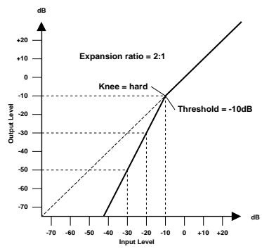
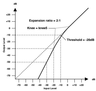
Expander
An expander is another form of automatic level control. By attenuating the signal below the threshold, the expander reduces low-level noise and effectively increases the dynamic range of the recorded material.
Expander (EXP) parameters:
| Parameter | Value | |
| Threshold (dB) | -54 to 0 | (55 points) |
| Ratio | 1.0, 1.1, 1.3, 1.5, 1.7, 2.0, 2.5, 3.0, 3.5, 4.0, 5.0, 6.0, 8.0, 10, 20, ∞ | (16 points) |
| Attack (ms) | 0 to 120 | (121 points) |
| Outgain (dB) | 0 to +18 | (36 points) |
| Knee | hard,1,2,3,4,5 | (6 points) |
| Release (ms) | 5 ms to 42.3 sec *1, 6 ms to 46.0 sec *2, 8 ms to 63.4 sec *3 | (160 points) |
1 These values are obtained when the sampling frequency is 48kHz .
2 These values are obtained when the sampling frequency is 44.1kHz .
*3 These values are obtained when the sampling frequency is 32kHz
Threshold determines the level of input signal required to trigger the expander. Signals above the threshold pass through unaffected. Signals at and below the threshold level are attenuated by the amount specified using the Ratio parameter. The trigger signal is determined using the KEY IN parameter.
Ratio controls the amount of expansion—the change in output signal level relative to change in input signal level. With a 1:2 ratio, for example, a 5 dB change in input level (below the threshold) results in a 10 dB change in output level. For a 1:5 ratio, a 2 dB change in input level (below the threshold) results in a 10 dB change in output level.
Attack controls how soon the signal is expanded once the expander has been triggered. With a fast attack time, the signal is expanded almost immediately. With a slow attack time, the initial transient of a sound passes through unaffected.
Out Gain sets the expander's output signal level.
Knee sets the transition of the signal at the threshold. With a hard knee, the transition between unexpanded and expanded signal is immediate. With the softest knee, knee5, the transition starts before the signal reaches the threshold and gradually ends above the threshold.
Release determines how soon the expander returns to its normal gain once the trigger signal level drops below the threshold.
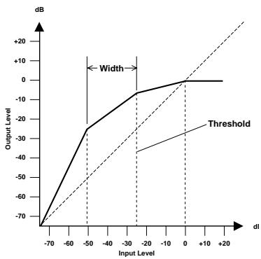
Compander
A compander is a compressor-expander—a combination of signal compression and expansion. The compander attenuates the input signal above the threshold as well as the level below the width. For very dynamic material, this program allows you to retain the dynamic range without having to be concerned with excessive output signal levels and clipping.
CompanderH (CPH) and CompanderS (CPS) parameters:
| Parameter | Value | |
| Threshold (dB) | -54 to 0 | (55 points) |
| Ratio | 1.0, 1.1, 1.3, 1.5, 1.7, 2.0, 2.5, 3.0, 3.5, 4.0, 5.0, 6.0, 8.0, 10, 20 | (15 points) |
| Attack (ms) | 0 to 120 | (121 points) |
| Outgain (dB) | -18 to 0 | (36 points) |
| Width (dB) | 1 to 90 | (90 points) |
| Release (ms) | 5 ms to 42.3 sec *1, 6 ms to 46.0 sec *2, 8 ms to 63.4 sec *3 | (160 points) |
1 These values are obtained when the sampling frequency is 48kHz .
2 These values are obtained when the sampling frequency is 44.1kHz .
*3 These values are obtained when the sampling frequency is 32kHz
Threshold determines the level of input signal required to trigger the compander. Signals above the threshold pass through unaffected. Signals at and below the threshold level are attenuated by the amount specified using the Ratio parameter. The trigger signal is determined using the KEY IN parameter.
Ratio controls the amount of companding—the change in output signal level relative to change in input signal level. With a 2:1 ratio, for example, a 10 dB change in input level (above the threshold) results in a 5 dB change in output level. The hard compiler (CPH) has a fixed ratio of 5:1 for expansion and the soft compiler (CPS) has a fixed ratio of 1.5:1 for expansion.
Attack controls how soon the signal is compounded once the compander has been triggered. With a fast attack time, the signal is compounded almost immediately. With a slow attack time, the initial transient of a sound passes through unaffected.
Out Gain sets the compander's output signal level.
Width is used to determine the distance, in decibels, between the expander and the compressor. With a width of 90 dB, the expander is effectively switched off and the compander is simply a compressor-limiter. With a smaller width (30dB) and a high threshold (0dB), the compander is an expander-compressor-limiter.
Release determines how soon the compander returns to its normal gain once the trigger signal level drops below the threshold.
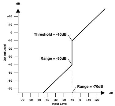
Gate and Ducking
A gate, or noise gate is an audio switch used to mute signals below a set threshold level. It can be used to suppress background noise and hiss from valve (tube) amps, effects pedals, and microphones.
Ducking is used to automatically reduce the levels of one signal when the level of a source signal exceeds a specified threshold. It is used for voice-over applications where, for example, level of background music is automatically reduced, allowing an announcer to be heard clearly.
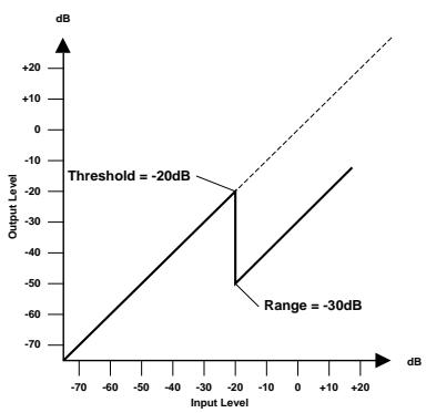
Gate (GAT) and Ducking (DUK) parameters:
| Parameter | Value | |
| Threshold (dB) | -54 to 0 | (55 points) |
| Range (dB) | -70 to 0 | (71 points) |
| Attack (ms) | 0 to 120 | (121 points) |
| Hold (ms) | 0.02 ms to 1.96s *1, 0.02 ms to 2.13 sec *2, 0.03 ms to 2.94 sec *3 | (216 points) |
| Decay (ms) | 5ms to 42.3s *1, 6 ms to 46.0 sec*2, 8 ms to 63.4 sec *3 | (160 points) |
1 These values are obtained when the sampling frequency is 48kHz .
2 These values are obtained when the sampling frequency is 44.1kHz .
*3 These values are obtained when the sampling frequency is 32kHz
Threshold sets the level at which the gate closes, cutting off the signal. Signals above the threshold level pass through unaffected. Signals at or below the threshold cause the gate to close.
For ducking, trigger signal levels at and above the threshold level activate ducking, and the signal level is reduced to a level set by the Range parameter.
The trigger signal is determined using the KEY IN parameter.
Range controls the level to which the gate closes. It can be used to reduce the signal level rather than cut it completely. At a setting of -70 dB, the gate closes completely when the input signal falls below the threshold. At a setting of -30 dB, the gate only closes so far allowing an attenuated signal through. At a setting of 0 dB, the gate has no effect. When signals are gated abruptly, the sudden cutoff can sound odd.
For ducking, a setting of -70 dB causes the signal to be virtually cutoff. At a setting of -30 dB the signal is ducked by 30dB . At a setting of 0dB , the duck has no effect.
Attack determines how fast the gate opens when the signal exceeds the threshold level. Slow attack times can be used to remove the initial transient edge of percussive sounds. Too slow an attack time makes some signals sound backwards.
For ducking, this controls how soon the signal is ducked once the duck has been triggered. With a fast attack time, the signal is ducked almost immediately. With a slow attack time, ducking fades the signal. Too fast an attack time may sound abrupt.
Hold sets how long the gate stays open or the ducking remains active once the trigger signal has fallen below the threshold level.
Decay controls how fast the gate closes once the hold time has expired. A longer decay time produces a more natural gating effect, allowing the natural decay of an instrument to pass through.
For ducking, this determines how soon the ducker returns to its normal gain after the hold time has expired.
DYNAMICS Display Function
- Use the (DYNAMICS) button to locate the DYNAMICS 1/2 page.

DYNAMICS
- Select a channel using the (SEL) buttons.
Note: Press the [SEL] button for the STEREO channel to access the dynamics processors for the output buses.
Dynamics can be applied to the input channels (MIC/LINE 1 through 16, LINE 17/18 through 23/24), the tape return channels (TAPE 1 through 16), the internal bus outputs (BUS 1 through 8), and the stereo output. For stereo and paired channels, the dynamics processor is applied equally to both channels.
Shown below is the DYNAMICS 1/2 page.
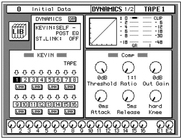
The DYNAMICS 1/2 page shows the dynamics settings of the currently selected channel.
The top of the page contains the dynamics LIB icon, the DYNAMICS icon, the main control prompts (KEY IN, ST.LINK, and optionally IN), the dynamics graph, and the gain reduction meter plus a level meter for the currently selected channel pair.
The bottom of the page is split into two main sections:
The first section shows the channel KEY IN settings and LINK icons. These settings can be changed using the CURSOR buttons, the encoder wheel, and [ENTER] button.
The second section contains the controls for adjusting the parameters for the currently selected channel. There are rotary icons for the threshold, ratio, output gain, attack, release, and so on, depending on which dynamics program you have selected. Use the CURSOR buttons to select the desired icon and adjust its value with the encoder wheel. Press the [ENTER] button to turn the dynamics processor on or off.
Patching in a Processor
- To turn the dynamics processor on, use the CURSOR buttons to select the DYNAMICS icon and press the (ENTER) button.
The icon changes from OFF to ON and is highlighted.
- Use the CURSOR buttons to select the KEY IN prompt and rotate the encoder wheel or press the (ENTER) button to select a trigger source.
- Use the CURSOR buttons to select the ST.LINK prompt and rotate the encoder wheel or press the (ENTER) button to turn the stereo link on or off.
- If the stereo link is on, use the CURSOR buttons to select the IN prompt and rotate the encoder wheel or press the (ENTER) button to select the channels to patch the dynamics processor into.
DYNAMICS Icon
The DYNAMICS ON/OFF icon is used to turn the dynamics processor on or off for the selected channel.
Control Prompts
The main control prompts are used to patch a dynamics processor into a channel or stereo pair:
| Prompt | Value |
| KEY IN | SELF - POST EQ, SELF - PRE EQ, LEFT - POST EQ, LEFT - PRE EQ, AUX 1, AUX 2 |
| ST.LINK | ON, OFF |
| IN | BOTH, L (left/odd), R (right/even) |
KEY IN selects the processor trigger source—the signal that triggers, or activates the processor. You can select the current channel either before or after equalization, the left channel (again either before or after equalization), or either AUX 1 or AUX 2.
You cannot select the left channel (before or after equalization) for the first input channel, MIC/LINE 1, the first tape return channel, TAPE 1, the first bus channel, or the stereo output channel.
ST.LINK determines if a channel pair is to be linked together. You cannot turn it off while channels are configured as a stereo pair.
IN appears only when ST.LINK is set to ON. It determines whether a dynamics processor is patched into just the left/odd channel (L), right/even channel (R), or both (BOTH).
Note: The DYNAMICS ON/OFF, KEY IN, ST.LINK, and IN parameters are not stored in the dynamics programs. These are individual channel (or stereo pair) parameters and are stored in the scene memories. DYNAMICS ON/OFF can be stored in channel programs.
Dynamics Processor Meters
The amount of processor gain reduction (GR) and the output signal levels are shown on the DYNAMICS 1/2 and 2/2 pages, as shown below.
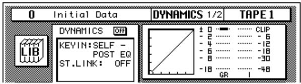
Gain reduction is the amount by which a signal's level is reduced. The output signal levels are conventional level meters which work from bottom-to-top. The GR level meter is inverted and works from top-to-bottom.
For compression, expansion, companding, and ducking, the GR meter operates when the processor is active, that is when it has been triggered by the KEY IN signal, and it shows the amount of signal level reduction.
For a gate, the processor is active when the input signal is below the threshold. So the GR meter operates when the input signal is below the threshold and also when there is no input signal.
Dynamics Graph
The dynamics graph gives you a visual indication of how the parameters of the dynamics processor will effect the signal as it passes through. The horizontal axis of the graph indicates the input signal. The vertical axis indicates the output signal:
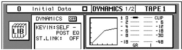
When the dynamics graph is a straight line at 45^ from the bottom left corner of the graph, it indicates that the dynamics processor will have no effect on the input signal.
KEY IN and LINK Indicators
The channel KEY IN settings and LINK settings are shown below.
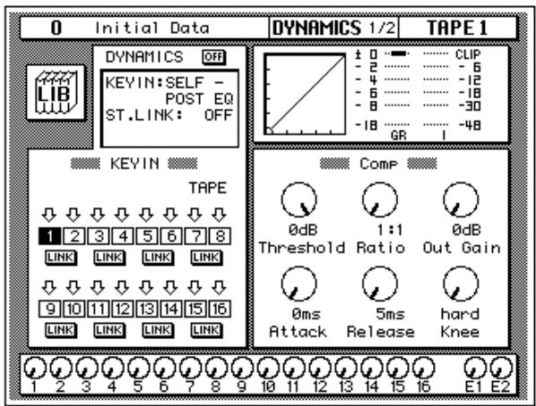
The settings can be changed with the CURSOR buttons, and the encoder wheel, or the [ENTER] button. The following table shows the meaning of the KEY IN icons:
| Icon | Meaning |
| ↓ | SELF – POST EQ—the trigger is taken from the current channel after the equalization. |
| ↓ | SELF – PRE EQ—the trigger is taken from the current channel before equalization. |
| ← | LEFT – POST EQ—the trigger is taken from the left channel after the equalization. |
| ← | LEFT – PRE EQ—the trigger is taken from the left channel before equalization. |
| A1 | AUX 1—the trigger is taken from the first auxiliary channel. |
| A2 | AUX 2—the trigger is taken from the second auxiliary channel. |
The KEY IN icons duplicate the KEY IN prompt, giving you a faster visual indication of the channel status. When the cursor is on a KEY IN icon, press the [ENTER] button to select that channel. The only way you can select the output buses 1 through 8 is with this method.
The LINK icons duplicate the ST.LINK prompt, giving you a faster visual indication of the channel status.
Dynamics Library
- Use the (DYNAMICS) button to locate the DYNAMICS 2/2 page.

The DYNAMICS Library page appears.
The Dynamics Library is used to access and store dynamics programs. There are 40 preset programs (1 to 40) for you to recall and 88 user programs (41 to 128 plus UNDO) for you to store your own dynamics programs.
You can access this page from the DYNAMICS 1/2 page by selecting the LIB icon with the CURSOR buttons and pressing the [ENTER] button.
Shown below is the DYNAMICS 2/2 page.
Recalling Dynamics Programs
- Select a channel using the (SEL) buttons.
- Use the CURSOR buttons to select the RECALL icon and rotate the encoder wheel to select a dynamics program.
- Press the (ENTER) button. The dynamics program is recalled.
Storing Dynamics Programs
- Use the CURSOR buttons to select the STORE icon and select a dynamics program with the encoder wheel.
- Use the CURSOR buttons and encoder wheel to name the program.
- Press the (ENTER) button. A confirmation dialog box appears.
- Select EXECUTE and press the (ENTER) button. The dynamics program is stored.
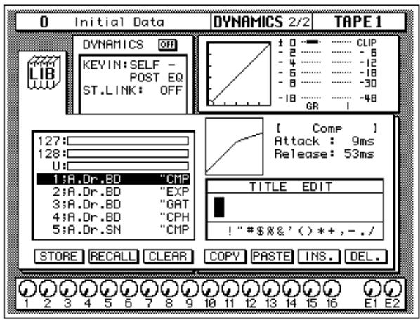
The top of the page shows the dynamics LIB icon, the main control prompts, the dynamics graph, and the gain reduction meter plus a level meter for the currently selected channel pair.
The middle of the page shows a scrolling list of dynamics programs. The name of the dynamics program under the cursor is highlighted. When the cursor is on the STORE, RECALL, CLEAR, COPY, or PASTE icons, the encoder wheel is used to scroll through the program list. A small diagram of the dynamics graph of the highlighted program is shown to the right along with its vital statistics, such as Attack, Hold, Decay, and so forth.
Beside the list of dynamics programs is the TITLE EDIT field. The CURSOR buttons are used to select the character, and the encoder wheel is used to change its value.
The bottom of the page contains several icons. Use the CURSOR buttons to select from the STORE, RECALL, CLEAR, COPY, PASTE, INS., and DEL. icons.
Exiting the Library
Selecting the LIB icon and pressing the [ENTER] button switches back to the DYNAMICS 1/2 page. You can also use the [DYNAMICS] button.
Icons
- STORE—This icon is used to store the current program to the library. Select the icon with the CURSOR buttons. Use the encoder wheel to select a program and press the [ENTER] button. The 02R displays a confirmation dialog box asking if you want to store your settings in the selected program. The dialog box has two icons: "CANCEL" and "EXECUTE".
Note: You can customize your 02R to prevent the confirmation dialog box appearing during the STORE operation. See "Preferences" on page 198 of the User's Guide for more information.
CANCEL is the default. To cancel the STORE operation, either press the [ENTER] button or wait about 10 seconds—the STORE operation will be automatically cancelled.
To store your settings, use the CURSOR buttons to select the "EXECUTE" icon and press the [ENTER] button. The program is stored.
When you confirm a STORE operation, any existing data in the selected program location is overwritten.
YOU SHOULD ALWAYS BE CAREFUL WHEN THE 02R DISPLAYS A CONFIRMATION Dialog Box!
- RECALL—This icon is used to recall a program from the library. Select the icon with the CURSOR buttons. Use the encoder wheel to select a program and press the [ENTER] button. The recalled program is now the current program.
- CLEAR—This icon is used to clear the contents of a dynamics program. Use the CURSOR buttons to select the icon. Use the encoder wheel to select a dynamics program and press the [ENTER] button. The 02R displays a confirmation dialog box asking if you want to clear the dynamics program. The dialog box has two icons: "CANCEL" and "EXECUTE".
Note: You can customize your 02R to prevent the confirmation dialog box appearing during the CLEAR operation. See “Preferences” on page 198 of the User's Guide for more information.
CANCEL is the default. To cancel the CLEAR operation, either press the [ENTER] button or wait about 10 seconds—the CLEAR operation will be automatically cancelled.
To clear the dynamics program, use the CURSOR buttons to select the "EXECUTE" icon and press the [ENTER] button. The program is cleared.
If you change your mind, the cleared dynamics program can be retrieved by recalling the Undo dynamics program (U).
-
COPY—This icon is used to copy the name of a library program. Select the icon with the CURSOR buttons. Use the encoder wheel to select a program and press the [ENTER] button. The program name is copied into an edit buffer.
-
PASTE—This icon is used to paste a program name previously selected with the COPY operation into the TITLE EDIT box. Select the icon with the CURSOR buttons and press the [ENTER] button. The program name is pasted from the edit buffer into the TITLE EDIT box for subsequent editing.
- INS.—This icon is used to insert blank characters into the TITLE EDIT box at the current cursor location. Select the icon with the CURSOR buttons and press the [ENTER] button.
- DEL.—This icon is used to delete characters from the TITLE EDIT box at the current cursor location. Select the icon with the CURSOR buttons and press the [ENTER] button.
UNDO Operation
When the 02R stores or recalls a program, the previous settings are always preserved in the UNDO buffer. If you discover you have made a mistake, you can always recall the UNDO buffer (displayed as "U:" in the scrolling list of programs). Use the CURSOR buttons to select the RECALL icon, then rotate the encoder wheel until the UNDO buffer is the current program, and press the [ENTER] button. The previous settings are restored.
Program Name
Dynamics program names can be up to 16 characters in length and can contain any of the following characters:
| ! | “ | # | $ | % | & | ' | ( | ) | * | + | , | - | . | / | |
| 0 | 1 | 2 | 3 | 4 | 5 | 6 | 7 | 8 | 9 | : | ; | < | = | > | ? |
| @ | A | B | C | D | E | F | G | H | I | J | K | L | M | N | O |
| P | Q | R | S | T | U | V | W | X | Y | Z | [ | \ | ] | ^ | _ |
| ` | a | b | c | d | e | f | g | h | i | j | k | l | m | n | o |
| p | q | r | s | t | u | v | w | x | y | z | { | | | } | ~ |
Preset Dynamics Program Parameters
The "Release", "Hold", and "Decay" values shown in the following table are valid when the 02R is set at a sampling frequency of 44.1kHz .
| No. | Name | Type | Parameter | Value | Description | |
| 1 | A.Dr.BD | "CMP | Compressor | Threshold (dB) | -24 | Compressor that gives the best results with an acoustic bass drum. |
| Ratio ( :1) | 3 | |||||
| Attack (ms) | 9 | |||||
| Outgain (dB) | 5.5 | |||||
| Knee | 2 | |||||
| Release (ms) | 58 | |||||
| 2 | A.Dr.BD | "EXP | Expander | Threshold (dB) | -23 | Expander for the same purpose as program 1. |
| Ratio ( :1) | 1.7 | |||||
| Attack (ms) | 1 | |||||
| Outgain (dB) | 3.5 | |||||
| Knee | 2 | |||||
| Release (ms) | 70 | |||||
| 3 | A.Dr.BD | "GAT | Gate | Threshold (dB) | -11 | Gate for the same purpose as program 1. |
| Range (dB) | -53 | |||||
| Attack (ms) | 0 | |||||
| Hold (ms) | 1.93 | |||||
| Decay (ms) | 400 | |||||
| 4 | A.Dr.BD | "CPH | CompanderH | Threshold (dB) | -11 | Hard compander for the same purpose as program 1. |
| Ratio ( :1) | 3.5 | |||||
| Attack (ms) | 1 | |||||
| Outgain (dB) | -1.5 | |||||
| Width (dB) | 7 | |||||
| Release (ms) | 192 | |||||
| 5 | A.Dr.SN | "CMP | Compressor | Threshold (dB) | -17 | Compressor that gives the best results with an acoustic snare drum. |
| Ratio ( :1) | 2.5 | |||||
| Attack (ms) | 8 | |||||
| Outgain (dB) | 3.5 | |||||
| Knee | 2 | |||||
| Release (ms) | 12 | |||||
| 6 | A.Dr.SN | "EXP | Expander | Threshold (dB) | -23 | Expander for the same purpose as program 5. |
| Ratio ( :1) | 2 | |||||
| Attack (ms) | 0 | |||||
| Outgain (dB) | 0.5 | |||||
| Knee | 2 | |||||
| Release (ms) | 151 | |||||
| 7 | A.Dr.SN | "GAT" | Gate | Threshold (dB) | -8 | Gate for the same purpose as program 5. |
| Range (dB) | -23 | |||||
| Attack (ms) | 1 | |||||
| Hold (ms) | 0.63 | |||||
| Decay (ms) | 238 | |||||
| 8 | A.Dr.SN | "CPS" | CompanderS | Threshold (dB) | -8 | Soft compander for the same purpose as program 5. |
| Ratio ( :1) | 1.7 | |||||
| Attack (ms) | 11 | |||||
| Outgain (dB) | 0.0 | |||||
| Width (dB) | 10 | |||||
| Release (ms) | 128 | |||||
| 9 | A.Dr.Tom | "EXP" | Expander | Threshold (dB) | -20 | Expander for acoustic toms automatically reduces the volume when the toms are not played, helping to differentiate the bass and snare drums clearly. |
| Ratio ( :1) | 2 | |||||
| Attack (ms) | 2 | |||||
| Outgain (dB) | 5.0 | |||||
| Knee | 2 | |||||
| Release (ms) | 749 | |||||
| 10 | A.Dr.OverTop | "GPS" | CompanderS | Threshold (dB) | -24 | Soft compander to emphasize the attack and ambience of cymbals using overhead microphones. It automatically reduces the volume when the cymbals are not played, helping differentiate the bass and snare drums clearly. |
| Ratio ( :1) | 2 | |||||
| Attack (ms) | 38 | |||||
| Outgain (dB) | -3.5 | |||||
| Width (dB) | 54 | |||||
| Release (ms) | 842 | |||||
| 11 | E.B.finger | "CMP" | Compressor | Threshold (dB) | -12 | Compressor to equalize the attack and volume level of a finger-picked electric bass guitar. |
| Ratio ( :1) | 2 | |||||
| Attack (ms) | 15 | |||||
| Outgain (dB) | 4.5 | |||||
| Knee | 2 | |||||
| Release (ms) | 470 | |||||
| 12 | E.B.slap | "CMP" | Compressor | Threshold (dB) | -12 | Compressor to equalize the attack and volume level of a slap electric bass guitar |
| Ratio ( :1) | 1.7 | |||||
| Attack (ms) | 6 | |||||
| Outgain (dB) | 4.0 | |||||
| Knee | hard | |||||
| Release (ms) | 133 | |||||
| 13 | Syn.Bass | "CMP" | Compressor | Threshold (dB) | -10 | Compressor to adjust and/or emphasize the level of a synth bass. |
| Ratio ( :1) | 3.5 | |||||
| Attack (ms) | 9 | |||||
| Outgain (dB) | 3.0 | |||||
| Knee | hard | |||||
| Release (ms) | 250 | |||||
| 14 | Piano1 | "CMP | Compressor | Threshold (dB) | -9 | Compressor to brighten the tonal color of a piano. |
| Ratio ( :1) | 2.5 | |||||
| Attack (ms) | 17 | |||||
| Outgain (dB) | 1.0 | |||||
| Knee | hard | |||||
| Release (ms) | 238 | |||||
| 15 | Piano2 | "CMP | Compressor | Threshold (dB) | -18 | A variation on program 14, adjusting the attack and entire level using a deeper threshold. |
| Ratio ( :1) | 3.5 | |||||
| Attack (ms) | 7 | |||||
| Outgain (dB) | 6.0 | |||||
| Knee | 2 | |||||
| Release (ms) | 174 | |||||
| 16 | E.Guitar | "CMP | Compressor | Threshold (dB) | -8 | Compressor for backing performances, such as electric rhythm guitar playing chords or arpeggios. |
| Ratio ( :1) | 3.5 | |||||
| Attack (ms) | 7 | |||||
| Outgain (dB) | 2.5 | |||||
| Knee | 4 | |||||
| Release (ms) | 261 | |||||
| 17 | A.Guitar | "CMP | Compressor | Threshold (dB) | -10 | A variation on program 16, intended for acoustic guitar playing rhythm chords or arpeggios. |
| Ratio ( :1) | 2.5 | |||||
| Attack (ms) | 5 | |||||
| Outgain (dB) | 1.5 | |||||
| Knee | 2 | |||||
| Release (ms) | 238 | |||||
| 18 | Strings1 | "CMP | Compressor | Threshold (dB) | -11 | Compressor for string instruments. This program was intended for violins. |
| Ratio ( :1) | 2 | |||||
| Attack (ms) | 33 | |||||
| Outgain (dB) | 1.5 | |||||
| Knee | 2 | |||||
| Release (ms) | 749 | |||||
| 19 | Strings2 | "CMP | Compressor | Threshold (dB) | -12 | A variation on program 18, intended for violas or cellos. |
| Ratio ( :1) | 1.5 | |||||
| Attack (ms) | 93 | |||||
| Outgain (dB) | 1.5 | |||||
| Knee | 4 | |||||
| Release (ms) | 1.35 S | |||||
| 20 | Strings3 | "CMP | Compressor | Threshold (dB) | -17 | A variation on program 18, intended for string instruments with a very low range, such as cellos or contrabass. |
| Ratio ( :1) | 1.5 | |||||
| Attack (ms) | 76 | |||||
| Outgain (dB) | 2.5 | |||||
| Knee | 2 | |||||
| Release (ms) | 186 | |||||
| No. | Name | Type | Parameter | Value | Description |
| 21 | BrassSection "CMP | Compressor | Threshold (dB) | -18 | Compressor intended for brass sounds with fast and strong attack. |
| Ratio ( :1) | 1.7 | ||||
| Attack (ms) | 18 | ||||
| Outgain (dB) | 4.0 | ||||
| Knee | 1 | ||||
| Release (ms) | 226 | ||||
| 22 | Syn.Pad "CMP | Compressor | Threshold (dB) | -13 | Compressor for synth pad, intended to prevent diffusion of the sound. |
| Ratio ( :1) | 2 | ||||
| Attack (ms) | 58 | ||||
| Outgain (dB) | 2.0 | ||||
| Knee | 1 | ||||
| Release (ms) | 238 | ||||
| 23 | SamplingPerc "CPS | CompanderS | Threshold (dB) | -18 | Compressor for sampled sounds to boost them to be as powerful and clear as the acoustic sounds. This program is for percussion sounds. |
| Ratio ( :1) | 1.7 | ||||
| Attack (ms) | 8 | ||||
| Outgain (dB) | -2.5 | ||||
| Width (dB) | 18 | ||||
| Release (ms) | 238 | ||||
| 24 | Sampling BD "CMP | Compressor | Threshold (dB) | -14 | A variation on program 23, intended for sampled bass drum sounds. |
| Ratio ( :1) | 2 | ||||
| Attack (ms) | 2 | ||||
| Outgain (dB) | 3.5 | ||||
| Knee | 4 | ||||
| Release (ms) | 35 | ||||
| 25 | Sampling SN "CMP | Compressor | Threshold (dB) | -18 | A variation on program 23, intended for sampled snare drum sounds. |
| Ratio ( :1) | 4 | ||||
| Attack (ms) | 8 | ||||
| Outgain (dB) | 8.0 | ||||
| Knee | hard | ||||
| Release (ms) | 354 | ||||
| 26 | Hip Comp "CPS | CompanderS | Threshold (dB) | -23 | A variation on program 23, intended for sampled sounds for loops. |
| Ratio ( :1) | 20 | ||||
| Attack (ms) | 15 | ||||
| Outgain (dB) | 0.0 | ||||
| Width (dB) | 15 | ||||
| Release (ms) | 163 | ||||
| 27 | Solo Vocal1 "CMP | Compressor | Threshold (dB) | -20 | Compressor suited for a solo vocal source. |
| Ratio ( :1) | 2.5 | ||||
| Attack (ms) | 31 | ||||
| Outgain (dB) | 2.0 | ||||
| Knee | 1 | ||||
| Release (ms) | 342 |
| No. | Name | Type | Parameter | Value | Description | |
| 28 | Solo Vocal2 | "CMP | Compressor | Threshold (dB) | -8 | A variation on program 27. |
| Ratio ( :1) | 2.5 | |||||
| Attack (ms) | 26 | |||||
| Outgain (dB) | 1.5 | |||||
| Knee | 3 | |||||
| Release (ms) | 331 | |||||
| 29 | Chorus | "CMP | Compressor | Threshold (dB) | -9 | A variation on program 27, intended for chorus vocals. |
| Ratio ( :1) | 1.7 | |||||
| Attack (ms) | 39 | |||||
| Outgain (dB) | 2.5 | |||||
| Knee | 2 | |||||
| Release (ms) | 226 | |||||
| 30 | Compander(H) | "CPH | CompanderH | Threshold (dB) | -10 | A template for the hard knee compander program. |
| Ratio ( :1) | 3.5 | |||||
| Attack (ms) | 1 | |||||
| Outgain (dB) | 0.0 | |||||
| Width (dB) | 6 | |||||
| Release (ms) | 250 | |||||
| 31 | Compander(S) | "CPS | CompanderS | Threshold (dB) | -8 | A template for the soft knee compander program. |
| Ratio ( :1) | 4 | |||||
| Attack (ms) | 25 | |||||
| Outgain (dB) | 0.0 | |||||
| Width (dB) | 24 | |||||
| Release (ms) | 180 | |||||
| 32 | Click Erase | "EXP | Expander | Threshold (dB) | -33 | Expander to remove click track sounds that may bleed out of the monitor headphones the musicians are using. |
| Ratio ( :1) | 2 | |||||
| Attack (ms) | 1 | |||||
| Outgain (dB) | 2.0 | |||||
| Knee | 2 | |||||
| Release (ms) | 284 | |||||
| 33 | Announcer | "CPH | CompanderH | Threshold (dB) | -14 | Hard compander reduces the level during the interval between the words, making the voice sound even. |
| Ratio ( :1) | 2.5 | |||||
| Attack (ms) | 1 | |||||
| Outgain (dB) | -2.5 | |||||
| Width (dB) | 18 | |||||
| Release (ms) | 180 | |||||
| 34 | Easy Gate | "GAT | Gate | Threshold (dB) | -26 | A template for the gate program. |
| Range (dB) | -56 | |||||
| Attack (ms) | 0 | |||||
| Hold (ms) | 2.56 | |||||
| Decay (ms) | 331 | |||||
| 35 | BGM Ducking | "DUK | Ducking | Threshold (dB) | -19 | Ducking background music for voiceovers, typically keyed from the announcer's channel. |
| Range (dB) | -22 | |||||
| Attack (ms) | 93 | |||||
| Hold (ms) | 1.20 S | |||||
| Decay (ms) | 6.32 S | |||||
| 36 | Limiter1 | "CMP | CompanderS | Threshold (dB) | -8 | A template for a limiter using the soft compander program. This program has a slow release. |
| Ratio ( :1) | 4 | |||||
| Attack (ms) | 25 | |||||
| Outgain (dB) | 0.0 | |||||
| Width (dB) | 24 | |||||
| Release (ms) | 180 | |||||
| 37 | Limiter2 | "CMP | Compressor | Threshold (dB) | 0 | A template for a limiter using the compressor program. This program is a PEAK STOP type. |
| Ratio ( :1) | ∞ | |||||
| Attack (ms) | 0 | |||||
| Outgain (dB) | 0.0 | |||||
| Knee | hard | |||||
| Release (ms) | 319 | |||||
| 38 | Total Comp1 | "CMP | Compressor | Threshold (dB) | -8 | Compressor intended to reduce the overall volume level. Use for the stereo out during mixdown. It is also interesting on stereo input signals. |
| Ratio ( :1) | 2.5 | |||||
| Attack (ms) | 60 | |||||
| Outgain (dB) | 0.0 | |||||
| Knee | 2 | |||||
| Release (ms) | 1.12 S | |||||
| 39 | Total Comp2 | "CMP | Compressor | Threshold (dB) | -18 | A variation of program 38. It has a harder compression ratio. |
| Ratio ( :1) | 3.5 | |||||
| Attack (ms) | 94 | |||||
| Outgain (dB) | 2.5 | |||||
| Knee | hard | |||||
| Release (ms) | 447 | |||||
| 40 | Total Comp3 | "CMP | Compressor | Threshold (dB) | -16 | A variation of program 38. It has an extreme compression ratio, almost a limiter in effect. |
| Ratio ( :1) | 6 | |||||
| Attack (ms) | 11 | |||||
| Outgain (dB) | 6.0 | |||||
| Knee | 1 | |||||
| Release (ms) | 180 | |||||
7
Auxiliary Channels
In this chapter...
About the 02R Auxiliaries 98
The AUX Buttons. 99
Stereo Input Channels. 101
AUX [ON] Button 101
AUX Pre or Post. 101
Monitor Mix 102
About the 02R Auxiliaries
The 02R has eight auxiliary sends: AUX 1, AUX 2, AUX 3, AUX 4, AUX 5, AUX 6, AUX 7, and AUX 8. The auxiliary sends can be configured pre-fader or post-fader.
AUX 7 and AUX 8 are used to feed the internal effects processors: Effect 1 and Effect 2. EFF 1 RTN and EFF 2 RTN are used to return the processed signals. Refer to "Internal Effects" on page 103 of the User's Guide for further details.
The other auxiliary sends can be used to feed external effects processors, foldback amplifiers, or multitrack recording equipment. When a send is used to feed an external effects processor, the processed signal can be returned via one of the stereo input channels or an unused monophonic input channel.
There are two different ways to access the auxiliary send channels:

DISPLAY ACCESS—AUX buttons
These buttons access the AUX pages that set the auxiliary send levels for the recording console.
- The [AUX 1] to [AUX 6] buttons set the auxiliary send levels to the corresponding auxiliary bus. You can also select whether to send the signal pre or post fader.
- The [AUX 7] and [AUX 8] buttons also set the send levels to the corresponding auxiliary bus and can select pre or post fader. However, these two sends are routed to the internal effects unit. Therefore, the buttons also allow you to select and set the effects parameters.
The channel aux send level controls for each aux send are displayed on two pages. The first page shows MIC/LINE aux controls. The second, TAPE and effects returns aux controls.
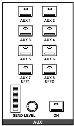
SELECTED CHANNEL—AUX controls
These buttons and controls set the auxiliary send levels for the currently selected channel.
- The [AUX 1] to [AUX 8] buttons allow you to select the auxiliary buses you want to send the selected channel signal to.
- The SEND LEVEL rotary encoder is used to set the level - indicated by the adjacent LED bargraph.
- The [ON] button is used to turn the send on or off. It allows you to make easy A-B comparisons.
The AUX Buttons
- Press the (AUX 1) button.

AUX 1
The AUX 1 page appears.
- Select a channel using the (SEL) buttons or the CURSOR buttons.
- To turn the send on, press the (ON) button in the AUX group of the SELECTED CHANNEL controls. The LED inset in the button illuminates.
Note: The [ON] button is the only way to turn the send on or off.
- To change the aux send from pre to post-fader, press the (ENTER) button. The icon is highlighted and the text changes to POST when the signal is post fader.
Note: Pre or post fader selection can only be made from the AUX pages.
- To change the signal level, adjust the corresponding fader or rotary encoder until the desired value is obtained.
Note: This example only shows AUX 1. The other channels are identical in function.
The AUX functions for AUX 1 through AUX 6 set the channel send levels to each of the auxiliary buses. With this function, you can select an auxiliary bus and then set the levels of a group of input channels simultaneously. You can also select whether to send the signal pre or post fader.
Fader Status
When the AUX functions are selected, the faders change from channel level controls to auxiliary send level controls. The faders automatically move to the corresponding auxiliary send levels.
Note: Avoid blocking the fader movements when the faders move to their auxiliary send positions by placing objects on the 02R. It is possible to damage the faders.
The AUX LED of the FADER STATUS indicator will illuminate to indicate the fader status. The number indicator corresponding to current the AUX button is also illuminated:
| FADER STATUS |
| 0 INPUT |
| ↓ AUX |
| 1 2 3 4 |
| 5 6 7 8 |
The send levels for the input channels are operated by their faders. Press the [FLIP] button, and the send levels for the tape return channels can be operated by the faders. You can also use the rotary encoders to set the tape return levels. The effect return levels can only be adjusted with the rotary encoders.
Note: When you press the [FLIP] button, the faders will automatically move to the levels of the opposite channels (from input levels to tape return levels). Avoid blocking the fader movements when the faders reposition by placing objects on the O2R. It is possible to damage the faders.
SELECTED CHANNEL Controls
You can use the SEND LEVEL encoder in the AUX group of the SELECTED CHANNEL controls to set the signal level to the auxiliary bus. The method of working with these controls is different than working with the DISPLAY ACCESS—AUX buttons.