SPX-Z18M - Speaker ALPINE - Free user manual and instructions
Find the device manual for free SPX-Z18M ALPINE in PDF.
User questions about SPX-Z18M ALPINE
0 question about this device. Answer the ones you know or ask your own.
Ask a new question about this device
Download the instructions for your Speaker in PDF format for free! Find your manual SPX-Z18M - ALPINE and take your electronic device back in hand. On this page are published all the documents necessary for the use of your device. SPX-Z18M by ALPINE.
USER MANUAL SPX-Z18M ALPINE
Points to Observe for Safe Usage
- Read this manual carefully before starting operation and use this system safely. We cannot be responsible for problems resulting from failure to observe the instructions in this manual.
- This manual uses various pictorial displays to show how to use this product safely and to avoid harm to yourself and others and damage to your property. Here is what these pictorial displays mean. Understanding them is important for reading this manual.
- Meaning of displays
| Warning | This label is intended to alert the user to the presence of important operating instructions. Failure to heed the instructions will result in severe injury or death. |
| Caution | This label is intended to alert the user to the presence of important operating instructions. Failure to heed the instructions can result in injury or material damage. |

Warning
DO NOT DISASSEMBLE OR ALTER. Doing so may result in an accident, fire or electric shock.
KEEP SMALL OBJECTS SUCH AS BATTERY OUT OF THE REACH OF CHILDREN. Swallowing them may result in serious injury. If swallowed, consult a physician immediately.
DO NOT INSTALL IN LOCATIONS WHICH MIGHT HINDER VEHICLE OPERATION, SUCH AS THE STEERING WHEEL OR GEARSHIFT. Doing so may obstruct forward vision or hamper movement etc. and results in serious accident.
DO NOT DAMAGE PIPE OR WIRING WHEN DRILLING HOLES. When drilling holes in the chassis for installation, take precautions so as not to contact, damage or obstruct pipes, fuel lines, tanks or electrical wiring. Failure to take such precautions may result in fire.
DO NOT USE BOLTS OR NUTS IN THE BRAKE OR STEERING SYSTEMS TO MAKE GROUND CONNECTIONS. Bolts or nuts used for the brake or steering systems (or any other safety-related system), or tanks should NEVER be used for installations or ground connections. Using such parts could disable control of the vehicle and cause fire etc.
DO NOT INSTALL THE MONITOR NEAR THE PASSENGER SEAT AIR BAG. If the unit is not installed correctly the air bag may not function correctly and when triggered the air bag may cause the monitor to spring upwards causing an accident and injuries.
MAKE THE CORRECT CONNECTIONS. Failure to make the proper connections may result in fire or product damage.

Caution
USE SPECIFIED ACCESSORY PARTS AND INSTALL THEM SECURELY. Be sure to use only the specified accessory parts. Use of other than designated parts may damage this unit internally or may not securely install the unit in place. This may cause parts to become loose resulting in hazards or product failure.
DO NOT INSTALL IN LOCATIONS WITH HIGH MOISTURE OR DUST. Avoid installing the unit in locations with high incidence of moisture or dust. Moisture or dust that penetrates into this unit may result in product failure.
HAVETHE WIRING AND INSTALLATIONDONE BY EXPERTS.The wiring and installation of this unit requires special technical skill and experience.To ensure safety, always contact the dealer where you purchased this product to have the work done.
ARRANGE THE WIRING SO IT IS NOT CRIMPED OR PINCHED BY A SHARP METAL EDGE. Route the cables and wiring away from moving parts (like the seat rails) or sharp or pointed edges. This will prevent crimping and damage to the wiring. If wiring passes through a hole in metal, use a rubber grommet to prevent the wire's insulation from being cut by the metal edge of the hole.
HALT USE IMMEDIATELY IF A PROBLEM APPEARS. Failure to do so may cause personal injury or damage to the product. Return it to your authorized Alpine dealer or the nearest Alpine Service Center for repairing.

Installation / Installation
Parts List / Lieste des pieces 3
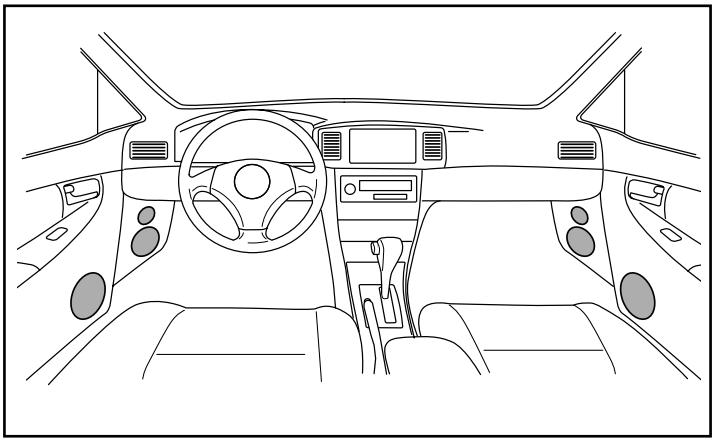
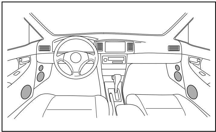
Woofer Installation / Installation du Woofer 4
Midrange Installation / Installation du haut-parleur medial 5
Tweeter Installation / Installation du Tweeter 6
Network Installation / Installation du circuit 7
Network connections / Connexions du circuit 8
Do not install the Crossover network where it will be exposed to moisture such as under the floor mat or near the air conditioner. This may cause a malfunction./
Insert the signal link jumpers highlighted in gray firmly following each connection example. If the jumper is not connected properly as described, it might result in malfunction of amplifier.
Connect properly by following the manual. Otherwise it might result in fire or accident.

Precaution
It is common knowledge that the automotive interior is one of the most inhospitable environments for high-fidelity sound, and that every vehicle poses its own unique set of installation and acoustic challenges. While many of these problems can often be overcome with proper speaker placement, equalization, or other techniques, the attempt is a time consuming task without guaranteed results. Yet with all these tools and methods available, it is surprising to realize that one of the most powerful tuning tools has been misunderstood or neglected by so many for so long. It is for this reason that Alpine has developed the most advanced crossover network design in the history of car audio.
Much of the difference between demo-board and in-car performance can be attributed to the fact that crossover networks have been traditionally tuned for only one specific application – usually the demo-board. Without taking into account typical real world installations, the transition between drivers and resultant frequency response will be degraded for the majority of vehicles that installers are confronted with today. Through Alpine's unique phase coherent flat summation design methodology, however, it is now possible to optimize performance for a variety of installations by intentionally altering various filter characteristics. By achieving an "in-phase" condition between drivers in the overlapping frequency range at the listening position, image smear, response aberrations and other typical problems can be dramatically reduced or eliminated altogether. This "phase linkage" technique can be thought of as a kind of passive time correction in the crossover region.
With Alpine's introduction of such revolutionary processing technologies as digital time correction and adaptive equalization, all of this may seem superlative. Unfortunately however, such processing can significantly increase system complexity and therefore may not be practical for every situation. Additionally, without careful use of time correction for each individual speaker in the system, integration problems between them can remain. Subsequently, it may be advantageous to use such processing to compensate for seating position bias in conjunction with the phase correction of the passive network for the transition between individual drivers. Simply stated, the flexibility of the AlpineF#1Status™ crossover network allows it to be a complimentary solution for achieving the best of both worlds, either as a stand alone solution or an integral component of a partially active system.
As with all AlpineF#1Status™ products, it is the attention to the smallest details that truly brings out ultimate performance... or in a word, MicroDynamics™. From the hand coated crosscut wood fiber cones to the symmetric drive motor structures, nothing is left to chance. This philosophy is carried throughout every aspect of the SPX-Z18T speaker system, including the components, layout and design of the crossover network. All series capacitors are the highest grade metalized polypropylene, and all series inductors are heavy gauge air core. Even parallel inductors are of powder core construction, to maximize consistency and sound quality. All elements are intentionally placed in such a way to as to minimize any chance for magnetic or thermal influence, and all signal path lengths are minimized with extra heavy circuit board traces. In the end, this level of quality and attention to detail has but one purpose, to bring true sonic realism to the automotive environment once and for all.
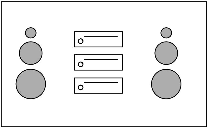
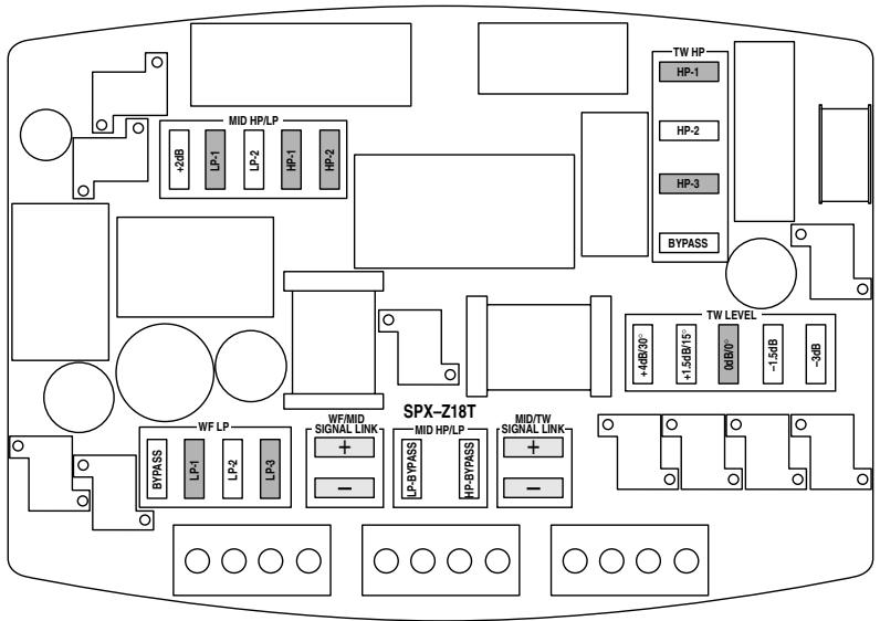
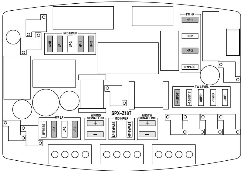
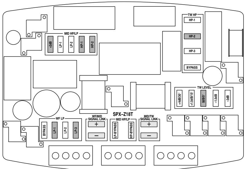
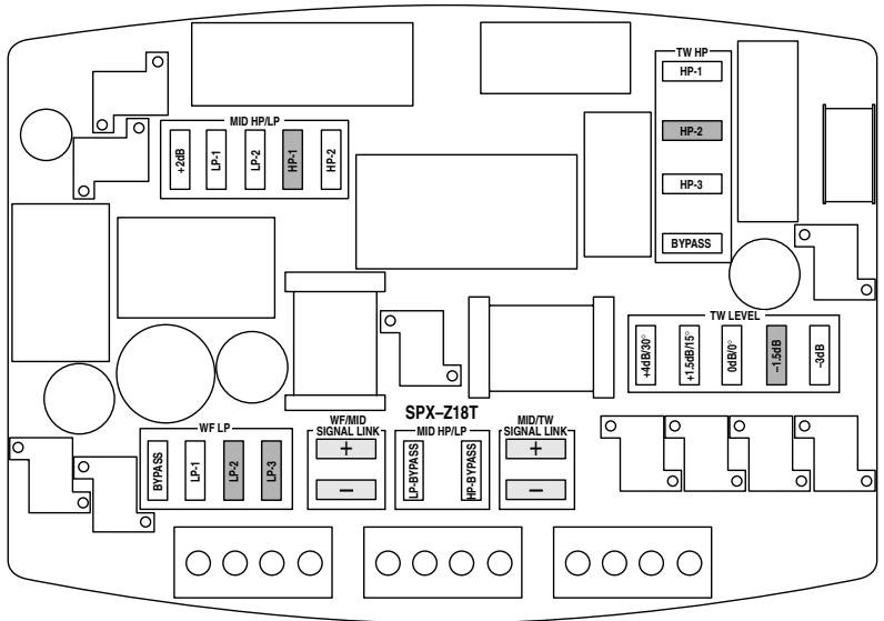
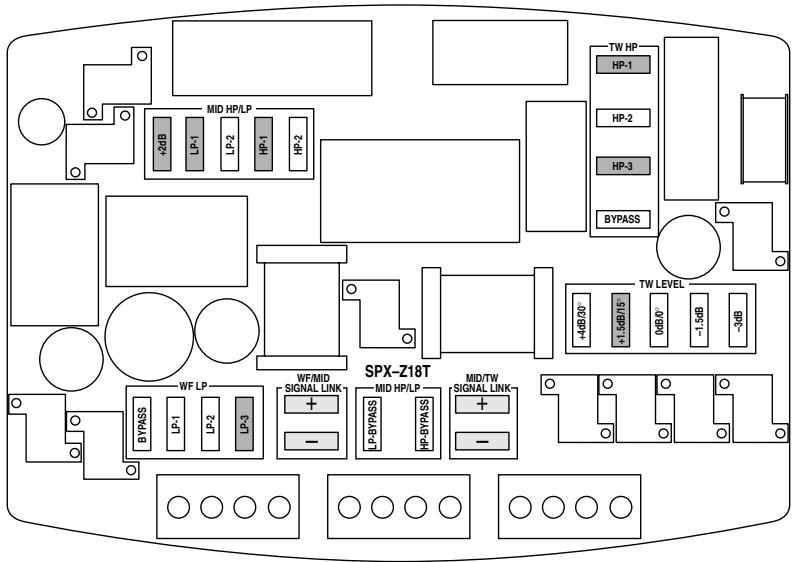
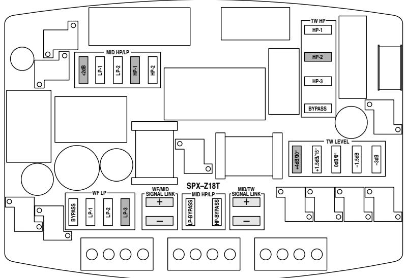
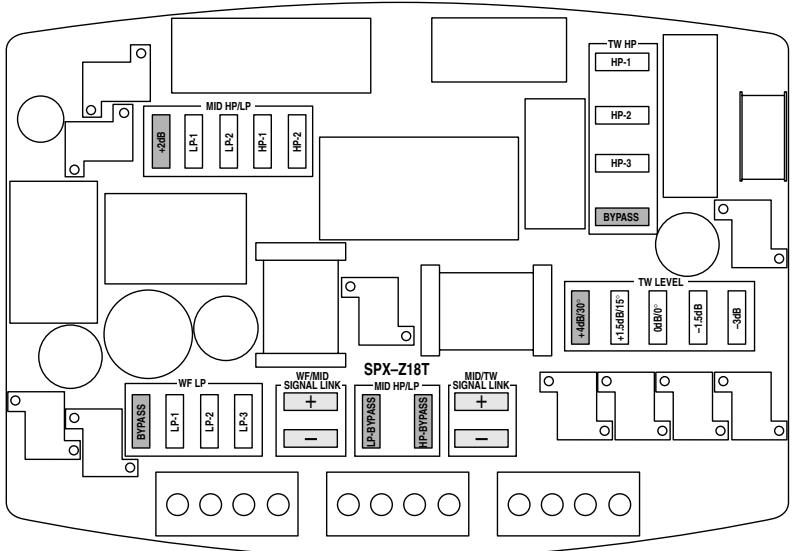
Jumper Group Function
Although recommendations are made for the most common system types in the following pages, there are actually over 1000 unique and useful jumper combinations available for a wide variety of vehicles, installations and personal tastes. While this flexibility has obvious advantages, too many choices can also be confusing. Therefore, it will be helpful to understand the function of each jumper group in order to tune the network more effectively:
TW-HP:
In addition to functioning as a high-pass filter, this section also provides the necessary adjustments for proper integration with the midrange. The transition between these two drivers in the frequency and time domains is essential to the total performance of a multi-element system, as it has a direct effect upon imaging, staging, focus and tonal balance. In real world installations, distance and angle of both drivers relative to the listener, their proximity to each other, and certainly the vehicle's interior also exert additional influence. In anticipation of this, variations of filter slope, Q, cut-off frequency and resultant phase shift are provided so that "phase linkage" and flat summation can be maintained. As a general reference, the layout and available filter types of the tweeter high-pass section are provided below:
TW LEVEL:
In general, this section provides precise level adjustment for optimum performance or personal taste. However, it also allows for "tilting" of the filter frequency response in order to compensate for the natural high frequency roll-off associated with off-axis listening angles. In other words, this jumper choice will have a direct effect on both Q and cut-off frequency of the various filter combinations listed above. This effect can be seen in the filter transfer function graphs for the various system types. If the TW-HP section is set to bypass in favor of an electronic crossover, the off-axis feature will no longer function, but basic level adjustment will still be possible.
MID HP/LP:
As a selectable bandpass filter for the midrange, the net effect of this section is naturally linked to the selections made in the tweeter high-pass and woofer low-pass sections. Achieving the most phase coherent and flat summation possible requires controlling the amount of inherent phase shift of each filter, and is directly related to the selection of filter order, Q and cut-off frequency. Again, this relationship is also affected by the distance and angle of each driver relative to the listener and their proximity to each other.
Since the acoustic center of the midrange will be farther back than the tweeter in nearly all applications, minimal delay is desirable in the midrange low-pass. Subsequently, this filter is of low order, and leaves much of the adjustment capability for the mid/tweeter transition to the tweeter high-pass section. For the midrange high-pass, higher order configurations are used in most applications to achieve phase linkage with the woofer (see WF-LP section). For general reference, the available midrange network configurations are listed below. In certain installations where positioning or placement necessitates level adjustment, a jumper is provided that boosts midrange output by approximately +2dB. As an additional note, either filter (high-pass or low-pass) may be bypassed independently for semi-active applications.
$$ R 6 = 1. 0 \Omega $$
$$ R 7 = 1. 0 \Omega $$
$$ R 8 = 2 2 \Omega $$
$$ C 3 = 1 8 \mu F $$
$$ \mathrm {C} 4 = 3 3 \mu \mathrm {F} $$
$$ C 5 = 1 0 \mu F $$
$$ \mathrm {L} 3 = 0. 3 2 \mathrm {m H} $$
$$ \mathrm {L} 4 = 2. 0 \mathrm {m H} $$
$$ \mathrm {L} 5 = 2. 9 \mathrm {m H} $$
1st Order HP:
- No HP jumpers
HP2 (semi-2nd Order)
3^rd Order HP:
HP1
4th Order HP:
HP1 + HP2
1st Order LP:
LP1
LP2
WF-LP:
While functioning as a low-pass filter for the woofer, this section also provides a wide degree of adjustments for optimizing performance and system integration. Since it is often difficult to position the woofer and midrange close together or at equal distances, it is critical to achieve phase linkage between them to avoid localization, image smear, poor staging, etc. Additionally, vehicle interior dimensions are typically close to the wavelength of the woofer/midrange crossover region, so it may be necessary to minimize overlap to reduce the chance of generating a complex canceling sound field or response aberrations. Therefore, a variety of higher order filter types and characteristics are provided in this section, making it possible to link the two drivers in relative phase for a smooth transition in many applications. Again, it is important to note that the selections made in both the WF-LP and MID-HP sections produce a net effect, and must be set in such a way so as to work together. As a general reference, the available woofer low-pass filter configurations are listed below.
1st Order:
- No HP jumpers
2^nd Order:
LP2
LP3
- LP2 + LP3
3^rd Order:
LP1
4th Order:
- LP1 + LP2
- LP1 + LP3
- LP1 + LP2 + LP3
SIGNAL LINK:
The signal link jumpers provide a parallel connection between the input sides of the terminal blocks, eliminating the need for extra terminals or wiring when using a single or dual input.
Caution:
These jumpers must be removed accordingly when used in a bi-amp or tri-amp configuration to prevent possible damage to amplifiers.
System Type 1
System Description
With all three drivers mounted close together and equidistant to the listening position, this is surely the most favorable configuration for a component speaker system. Although such an installation may not often be practical in situations other than the demoboard, it is certainly possible given the custom fabrication techniques available today. In anticipation this, a degree of tolerance is built into the settings described below for the most likely cases, though some experimentation may be necessary if all conditions cannot be met. If choosing to go beyond the recommended settings or utilizing the network in a partially active mode, keep in mind that phase coherence and flat summation remains critical even in the idyllic flat baffle situation, as each driver type exhibits unique phase and group delay characteristics.
- Type-1A is the default setting of the network, and assumes essentially on-axis positioning and equal pathlength of all drivers relative to the listening position.
- Type-1B is for such cases where pathlength is nearly the same to all drivers, but where the mounting surface orientation creates a uniform but fairly extreme off-axis listening angle.
Network Jumper Setting
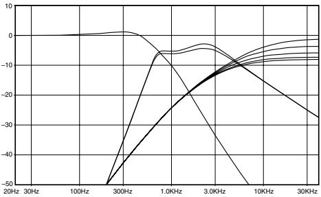
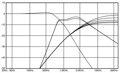
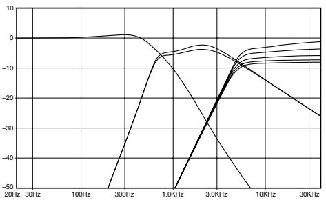
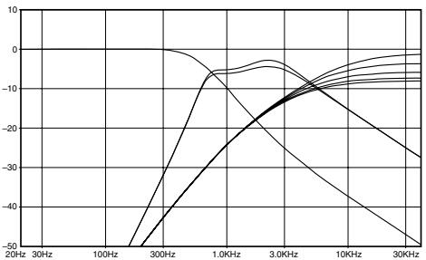
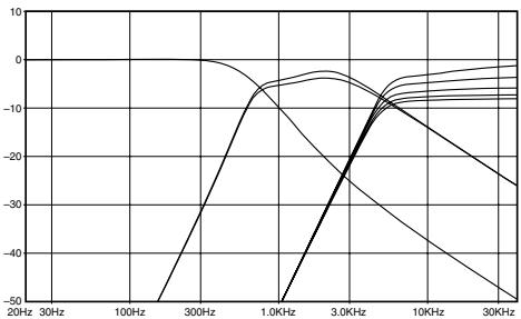
Type-1A: Pathlength to the listening position is considered to be basically equal in this case (ideally 2-3m away), with relative on-axis positioning of all drivers. Phase linkage is accomplished with a low Q 2^nd Order high-pass filter on the tweeter, 1^st Order low-pass and 4^th Order high-pass on the midrange, and a semi- 4^th Order low-pass on the woofer. This results in acoustic crossover points of 3.8kHz and 700Hz respectively.
Notes:
- Highlighted tweeter level jumpers are the recommended settings for each configuration, but user adjustment may be desirable.
- Transfer function simulations only illustrate the effect of the filter upon the input signal, and therefore do not represent the actual frequency response of the system.
- If separate channels of amplification are used (bi-wire or tri-wire mode), the appropriate signal link jumpers must be removed.
Network Jumper Setting
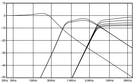
Type-1B: While the mounting configuration is the same as Type-1A, this network setting provides a variation for when personal taste, positioning or vehicle acoustics necessitates more high frequency output from the midrange and tweeter. Rear deck installation is one particular example where the extreme off-axis positioning will require such level compensation due to the natural rolloff. Although this will also result in some additional delay of the woofer, it does not exert significant influence in this case. The resultant acoustic crossover points are the same as indicated above.
Notes:
- Highlighted tweeter level jumpers are the recommended settings for each configuration, but user adjustment may be desirable.
- Transfer function simulations only illustrate the effect of the filter upon the input signal, and therefore do not represent the actual frequency response of the system.
- If separate channels of amplification are used (bi-wire or tri-wire mode), the appropriate signal link jumpers must be removed.
System Description
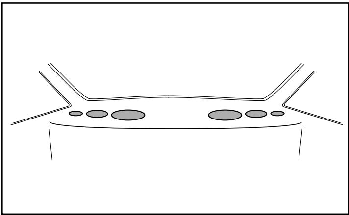
As one of the more common applications, this installation type is the most likely to be accommodated by factory speaker locations to some degree, thus requiring the least amount of custom fabrication. However, due to the mounting arrangement and surface orientation, it also results in significant differences in distance and angle of all three drivers relative to the listener. In order to optimize performance in this case, it especially critical to link each driver together in relative phase throughout the transitional crossover regions, while also taking into account the frequency response effects of the various off-axis listening angles of each driver. Two network configurations are provided for the most typical variations of this installation type, each employing specific phase correction and response compensation. Again, please note that the tuning of the settings below considers the best balance between driver and passenger listening positions, so all distances and angles are referenced to the nearest side.
Also worth noting is the fact that the shorter near side pathlengths to the midrange and tweeter will result in more dramatic seating position bias than other installation types. While it is possible to adjust each network individually in order to specifically tune for one listening position, it will often be more beneficial to utilize basic time correction to correct for this left/right pathlength difference if available. In general though, a high tweeter location is thought to be advantageous for improving perceived height and width of the soundstage, as well as achieving a strong high frequency output level.
- Type-2A takes into account that all drivers are mounted more or less flush to the panel on a mostly flat vertical surface such as the door, thus presenting varying degrees of both axis and distance of each driver to the listener.
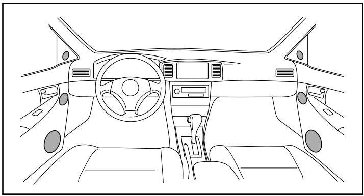
- Type-2B is the same as above, but assumes the woofer somewhat farther away than is typical. This will accommodate different vehicle types as well as kick panel mounting of the woofer.
Network Jumper Setting
Type-2A: For the tweeter in this case, pathlength from the listening position is considered to be 85cm , at approximately 15- 20^ off-axis. Located at a moderate vertical distance down from the tweeter and basically flush to the panel, the midrange is 8.5cm farther away and presents a listening angle of about 40 - 50^ . Due to the low door woofer location however, the listening angle for the woofer is close to 60^ off-axis, with its acoustic center 8cm farther relative to the mid. For the tweeter/mid transition, a 3rd order high-pass and semi-1st order low-pass with increased level on the mid are engaged, resulting in a summation point of 4kHz . Optimum integration between the woofer and mid is then achieved with 4th order high-pass and low-pass at 700Hz .
Notes:
- Highlighted tweeter level jumpers are the recommended settings for each configuration, but user adjustment may be desirable.
- Transfer function simulations only illustrate the effect of the filter upon the input signal, and therefore do not represent the actual frequency response of the system.
- If separate channels of amplification are used (bi-wire or tri-wire mode), the appropriate signal link jumpers must be removed.
Network Jumper Setting
Type-2B: Tweeter and midrange positioning are the same as in Type-2A, but the woofer is located farther forward. This results in a more extreme woofer listening angle of approximately 70^ , with a delay of 28cm relative to the mid. Subsequently, level attenuation is applied to both the tweeter and mid while also adjusting filter characteristics appropriately for the mid/woofer transition. In this case, changing the midrange high-pass to a low Q 3rd order and the woofer low-pass to very high Q 2nd order results in an acoustic crossover point of 500Hz.
Notes:
- Highlighted tweeter level jumpers are the recommended settings for each configuration, but user adjustment may be desirable.
- Transfer function simulations only illustrate the effect of the filter upon the input signal, and therefore do not represent the actual frequency response of the system.
- If separate channels of amplification are used (bi-wire or tri-wire mode), the appropriate signal link jumpers must be removed.
System Description
Although the midrange and tweeter are mounted close together in this case, space limitations, aesthetics or practicality requires that the woofer be mounted separately. Utilizing the kick panel and door locations is the most common method, though it is certainly not the only one. What is most significant, is that by mounting the midrange and tweeter in close proximity with a minimized off-axis angle at the greatest distance possible, it provides one of the best arrangements for optimum imaging in the vehicle. Since there are varying degrees of axis and pathlength that will be achievable in some installations, two basic configurations are provided to accommodate the most common cases. Keep in mind that the network tuning described below considers the best balance between driver and passenger listening positions, so all distances and angles are referenced to the nearest side.
- Type-3A assumes that both the midrange and tweeter are mounted close together in the same plane, and therefore relatively on-axis and equidistant to the listener.
- Type-3B takes into consideration that the tweeteter and midrange are mounted basically flush to the panel with little or no build out. This results in both an off-axis condition and a difference in pathlength.
Network Jumper Setting
Type-3A: Both midrange and tweeter are at the same distance and angle, while the woofer position is closer and fairly off-axis to the listening position. Therefore, the acoustic center of the woofer is considered to be the closest driver by approximately 18.5cm. In order to minimize overlap while maintaining phase coherence between the mid and woofer, a 3^rd order high-pass and semi- 2^nd order low-pass are applied, resulting in a summation point of 600Hz. Since the tweeter and midrange are farther away, minimal delay and some level adjustment are desirable, utilizing a low Q semi- 2^nd order high-pass on the tweeter and a 1^st order low-pass on the mid for a resultant acoustic crossover point of 3.8KHz.
Notes:
- Highlighted tweeter level jumpers are the recommended settings for each configuration, but user adjustment may be desirable.
- Transfer function simulations only illustrate the effect of the filter upon the input signal, and therefore do not represent the actual frequency response of the system.
- If separate channels of amplification are used (bi-wire or tri-wire mode), the appropriate signal link jumpers must be removed.
Network Jumper Setting
Type-3B: Despite the fact that the midrange and tweeter are mounted in the same plane and in close proximity, their orientation results in the acoustic center of the midrange being farther away. Therefore, the midrange is considered to be 8.5cm farther than the tweeter, while the woofer is approximately 25cm closer than the midrange.
For the upper crossover point, a relatively low Q 3^rd order high-pass filter is employed on the tweeter in conjunction with a semi-1 ^st order low pass on the mid. Then for the midrange to woofer transition, a 3^rd order high-pass on the mid integrates well with a semi-2 ^nd order low-pass on the woofer. Together, these filter combinations result in acoustic crossover points of 3.8kHz and 600Hz.
Notes:
- Highlighted tweeter level jumpers are the recommended settings for each configuration, but user adjustment may be desirable.
- Transfer function simulations only illustrate the effect of the filter upon the input signal, and therefore do not represent the actual frequency response of the system.
- If separate channels of amplification are used (bi-wire or tri-wire mode), the appropriate signal link jumpers must be removed.
System Type 4
System Description
In this system type, some level of external signal processing is available, allowing use of the network in a partially active mode. Although speakers may be mounted in a wide variety locations in this case, it is recommended that traditional techniques be used regarding both positioning and placement.
Fully active systems have often been considered to be the most flexible, but they are certainly not the most effective or practical in all cases. While it is usually considered best to have individual channels of amplification for each driver, it may not always be appropriate to use the electronic crossover that is included with many amplifiers today. This can be especially true for systems where optimum placement or tuning is not possible, as it may be advantageous to use this network for its various phase correction and response compensation capabilities. Additionally, digital time correction can be a complimentary solution to correct for left/right seating position bias, while leaving the network in place to achieve phase linkage between the woofer, midrange and tweeter. The only situation where the network might not be used at all, is in a fully active system with individual channels of amplification, equalization and time correction available for each driver.
There are essentially three ways to use the network in a partially active mode:
1) Use all functions of the network appropriate for the installation type, but engage an electronic high-pass on the woofer for increased power handling (usually recommended in systems with subwoofoers).
2) If only a limited number of channels or coarse adjustment of digital time correction is available, use it to compensate for basic left/right seating position bias while using the appropriate network setting to achieve phase linkage between individual drivers.
3) Bypass particular high-pass or low-pass section of the network in favor of an electronic crossover, still utilizing the phase and response adjustments of the others.
Notes:
- The +4dB / 30^ setting in the TW LEVEL jumper group bypasses all resistors in the tweeter section.
- If separate channels of amplification are used (bi-wire or tri-wire mode), the appropriate signal link jumpers must be removed.
| Type | Component 3-way speaker |
| Power Handling (peak/RMS) | 200/50W |
| Impedance | 4 Ω |
| Frequency Response | 35-60 kHz |
| Net Weight | 11 kg |
| Drivers | Woofer | Midrange | Tweeter |
| General | |||
| Speaker size | 7"(18cm) | 4"(10cm) | 1-1/2"(39mm) |
| Power Handling (RMS) | 50W | 40W(>200Hz) | 40W(>5kHz) |
| Voice Coil Impedance (nom) | 4 Ω | 4 Ω | 4 Ω |
| Frequency Response (-10dB) | 8kHz | 15kHz | 60kHz |
| Sensitivity (@ 2.83V/ 1m) | 89dB | 88dB | 94.5dB |
| Voice Coil Diameter | 38mm | 38mm | 25mm |
| Linear Excursion (Xmax) | ± 6.5mm | ± 3mm | ± 0.2mm |
| Mechanical Excursion (p-p) | ± 11mm | ± 5mm | ± 1.6mm |
| Mechanical | |||
| Frame Material | Aluminium | Aluminium | Aluminium |
| Magnetic Material | Strontium | Neodymium | Neodymium |
| Diaphragm Material | Wood Fiber | Wood Fiber | Textile |
| Diaphragm Shape | Cross-Cut | Cross-Cut | Ring Radiator |
| Surround Material and Type | Low Loss Rubber | Low Loss Rubber | |
| Speaker Weight | 2000g | 550g | 400g |
| Magnet Weight | 700g | 75g | 80g |
| Magnet System Type | Symmetric Drive | ||
| Depth | 76.2mm | 45.4mm | 25.1mm |
| Cut- out diameter | 148mm | 93mm | 76mm |
| Thiele/ Small | |||
| ReDC | 3.5 ohm | 3.2 ohm | 3.0 ohm |
| Fs | 34Hz | 72Hz | 520Hz |
| Qts | 0.45 | 0.35 | 0.32 |
| Qms | 5.8 | 5.5 | 2.29 |
| Qes | 0.48 | 0.37 | 0.38 |
| Vas | 34ltr. | 2.7ltr. | 14ml |
| Sd | 150cm² | 52cm² | 5.6cm² |
| Le | 0.28mH | 0.23mH | 0.01mH |
| Cms | 1.08mm/N | 0.7mm/N | 0.3mm/N |
| Mms | 20g | 7g | 0.3g |
| BI | 5.6Tm | 5.3Tm | 2.8Tm |
| Sealed box | |||
| Recommended Volume (Butterworth) | 23ltr. | 0.8ltr. |
ALPINE
ALPINE ELECTRONICS MARKETING, INC.
1-1-8 Nishi Gotanda,
Shinagawa-ku, Tokyo 141-0031, Japan
Phone 03-5496-8231
ALPINE ELECTRONICS OF AMERICA, INC.
19145 Gramercy Place, Torrance,
California 90501, U.S.A.
Phone 1-800-ALPINE-1 (1-800-257-4631)
ALPINE ELECTRONICS OF CANADA, INC.
7300 Warden Ave., Suite 203, Markham,
Ontario L3R 9Z6, Canada
Phone 1-800-ALPINE-1 (1-800-257-4631)
ALPINE ELECTRONICS OF AUSTRALIA PTY. LTD.
6-8 Fiveways Boulevard Keysborough,
Victoria 3173, Australia
Phone 03-9769-0000
ALPINE ELECTRONICS GmbH
Kreuzerkamp 7, 40878 Ratingen, Germany
Phone 02102-4550
ALPINE ELECTRONICS OF U.K. LTD.
Alpine House
Fletchamstead Highway,
Coventry CV4 9TW, U.K.
Phone 0870-33 33 763
ALPINE ELECTRONICS FRANCE S.A.R.L.
(RCS PONTOISE B 338 101 280)
98, Rue de la Belle Etoile, Z.I. Paris
Nord II, B.P. 50016, 95945 Roissy
Charles de Gaulle Cedex, France
Phone 01-48638989