SPX-Z15M - Car stereo ALPINE - Free user manual and instructions
Find the device manual for free SPX-Z15M ALPINE in PDF.

User questions about SPX-Z15M ALPINE
0 question about this device. Answer the ones you know or ask your own.
Ask a new question about this device
Download the instructions for your Car stereo in PDF format for free! Find your manual SPX-Z15M - ALPINE and take your electronic device back in hand. On this page are published all the documents necessary for the use of your device. SPX-Z15M by ALPINE.
USER MANUAL SPX-Z15M ALPINE
natural_image
Black-and-white photo of an Alpine Sound System with two speakers and a speakerhead, no visible text or symbols on the devices themselves.
Points to Observe for Safe Usage
- Read this manual carefully before starting operation and use this system safely. We cannot be responsible for problems resulting from failure to observe the instructions in this manual.
- This manual uses various pictorial displays to show how to use this product safely and to avoid harm to yourself and others and damage to your property. Here is what these pictorial displays mean. Understanding them is important for reading this manual.
• Meaning of displays
| Warning | This label is intended to alert the user to the presence of important operating instructions.Failure to heed the instructions will result in severe injury or death. |
| Caution | This label is intended to alert the user to the presence of important operating instructions.Failure to heed the instructions can result in injury or material damage. |

Warning
DO NOT DISASSEMBLE OR ALTER. Doing so may result in an accident, fire or electric shock.
KEEP SMALL OBJECTS SUCH AS BATTERY OUT OF THE REACH OF CHILDREN. Swallowing them may result in serious injury. If swallowed, consult a physician immediately.
DO NOT INSTALL IN LOCATIONS WHICH MIGHT HINDER VEHICLE OPERATION, SUCH AS THE STEERING WHEEL OR GEARSHIFT. Doing so may obstruct forward vision or hamper movement etc. and results in serious accident.
DO NOT DAMAGE PIPE OR WIRING WHEN DRILLING HOLES. When drilling holes in the chassis for installation, take precautions so as not to contact, damage or obstruct pipes, fuel lines, tanks or electrical wiring. Failure to take such precautions may result in fire.
DO NOT USE BOLTS OR NUTS IN THE BRAKE OR STEERING SYSTEMS TO MAKE GROUND CONNECTIONS. Bolts or nuts used for the brake or steering systems (or any other safety-related system), or tanks should NEVER be used for installations or ground connections. Using such parts could disable control of the vehicle and cause fire etc.
DO NOT INSTALL THE MONITOR NEAR THE PASSENGER SEAT AIR BAG. If the unit is not installed correctly the air bag may not function correctly and when triggered the air bag may cause the monitor to spring upwards causing an accident and injuries.
MAKE THE CORRECT CONNECTIONS. Failure to make the proper connections may result in fire or product damage.

Caution
USE SPECIFIED ACCESSORY PARTS AND INSTALL THEM SECURELY. Be sure to use only the specified accessory parts. Use of other than designated parts may damage this unit internally or may not securely install the unit in place. This may cause parts to become loose resulting in hazards or product failure.
DO NOT INSTALL IN LOCATIONS WITH HIGH MOISTURE OR DUST. Avoid installing the unit in locations with high incidence of moisture or dust. Moisture or dust that penetrates into this unit may result in product failure.
HAVE THE WIRING AND INSTALLATION DONE BY EXPERTS. The wiring and installation of this unit requires special technical skill and experience. To ensure safety, always contact the dealer where you purchased this product to have the work done.
ARRANGE THE WIRING SO IT IS NOT CRIMPED OR PINCHED BY A SHARP METAL EDGE. Route the cables and wiring away from moving parts (like the seat rails) or sharp or pointed edges. This will prevent crimping and damage to the wiring. If wiring passes through a hole in metal, use a rubber grommet to prevent the wire's insulation from being cut by the metal edge of the hole.
HALT USE IMMEDIATELY IF A PROBLEM APPEARS. Failure to do so may cause personal injury or damage to the product. Return it to your authorized Alpine dealer or the nearest Alpine Service Center for repairing.

Installation / Installation
text_image
Technical diagram of a mechanical device with exploded view and labeled component X5text_image
Technical diagram of a mechanical assembly with labeled parts and cross-sectional views (X5, X4)natural_image
Simple line drawing of a cable being inserted into a plug socket (no text or symbols)text_image
Technical diagram of a mechanical assembly with labeled components and cross-section view X1text_image
Technical diagram showing exploded view of a mechanical component with labeled parts and assembly stepstext_image
Technical diagram of a mechanical assembly with labeled components and a numbered inset showing part 13 and X5.
natural_image
Simple line drawing of a mechanical component with wires, no text or symbols presentDo not install the Crossover network where it will be exposed to moisture such as under the floor mat or near the air conditioner. This may cause a malfunction./
Insert the signal link jumpers highlighted in gray firmly following each connection example. If the jumper is not connected properly as described, it might result in malfunction of amplifier.
It is common knowledge that the automotive interior is one of the most inhospitable environments for high-fidelity sound, and that every vehicle poses its own unique set of installation and acoustic challenges. While many of these problems can often be overcome with proper speaker placement, equalization, or other techniques, the attempt is a time consuming task without guaranteed results. Yet with all these tools and methods available, it is surprising to realize that one of the most powerful tuning tools has been misunderstood or neglected by so many for so long. It is for this reason that Alpine has developed the most advanced crossover network design in the history of car audio.
Much of the difference between demo-board and in-car performance can be attributed to the fact that crossover networks have been traditionally tuned for only one specific application – usually the demo-board. Without taking into account typical real world installations, the transition between drivers and resultant frequency response will be degraded for the majority of vehicles that installers are confronted with today. Through Alpine's unique phase coherent flat summation design methodology, however, it is now possible to optimize performance for a variety of installations by intentionally altering various filter characteristics. By achieving an “in-phase” condition between drivers in the overlapping frequency range at the listening position, image smear, response aberrations and other typical problems can be dramatically reduced or eliminated altogether. This “phase linkage” technique can be thought of as a kind of passive time correction in the crossover region.
With Alpine's introduction of such revolutionary processing technologies as digital time correction and adaptive equalization, all of this may seem superlative. Unfortunately however, such processing can significantly increase system complexity and therefore may not be practical for every situation. Additionally, without careful use of time correction for each individual speaker in the system, integration problems between them can remain. Subsequently, it may be advantageous to use such processing to compensate for seating position bias in conjunction with the phase correction of the passive network for the transition between individual drivers. Simply stated, the flexibility of the AlpineF#1Status™ crossover network allows it to be a complimentary solution for achieving the best of both worlds, either as a stand alone solution or an integral component of a partially active system.
As with all AlpineF#1Status™ products, it is the attention to the smallest details that truly brings out ultimate performance... or in a word, MicroDynamics™. From the hand coated crosscut wood fiber cones to the symmetric drive motor structures, nothing is left to chance. This philosophy is carried throughout every aspect of the SPX-Z15M speaker system, including the components, layout and design of the crossover network. All series capacitors are the highest grade metalized polypropylene, and all series inductors are heavy gauge air core. All elements are intentionally placed in such a way to as to minimize any chance for magnetic or thermal influence, and all signal path lengths are minimized with extra heavy circuit board traces. In the end, this level of quality and attention to detail has but one purpose, to bring true sonic realism to the automotive environment once and for all.
Jumper Group Function
Although recommendations are made for the most common system types in the following pages, there are actually over 250 unique and useful jumper combinations available for a wide variety of vehicles, installations and personal tastes. While this flexibility has obvious advantages, too many choices can also be confusing. Therefore, it will be helpful to understand the function of each jumper group in order to tune the network more effectively:
TW-HP:
Although essentially a selectable high-pass filter, this section provides the major part of the phase correction and response compensation of the network. By altering the slope, Q, cut-off frequency and phase shift of the high-pass filter, it is possible to create “phase linkage” with the woofer. This proper summation in the frequency and time domains is what produces the seamless blend necessary for optimum imaging, staging, focus and tonal balance in a multi-element system.
These relationships are affected by the distance and angle of both drivers relative to the listener, their proximity to each other, and certainly the vehicle's interior as well. While it is beyond the scope of this manual to describe each potential network combination in detail, the following filter types are possible for the high-pass section of the network:
text_image
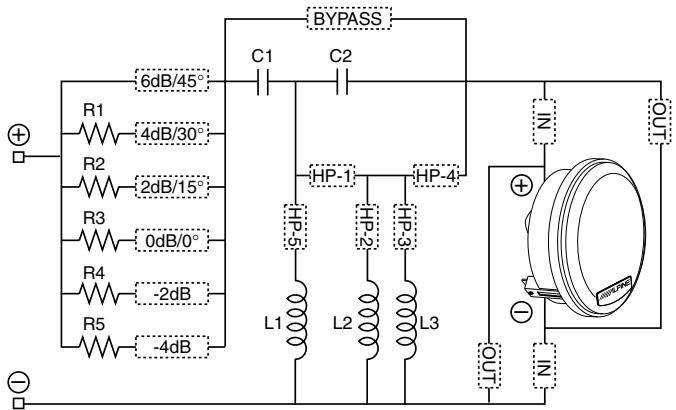
BYPASS 6dB/45° C1 C2 R1 4dB/30° R2 2dB/15° R3 0dB/0° R4 -2dB R5 -4dB HP-1 HP-4 L1 L2 L3 OUT N + - N$$ R 1 = 1. 0 \Omega $$
$$ \mathrm{R} 2 = 2. 2 \Omega $$
$$ \mathsf {R 3} = 3. 9 \Omega $$
$$ \mathsf {R 4} = 5. 6 \Omega $$
$$ \mathsf {R 5} = 8. 2 \Omega $$
$$ \mathrm{C} 1 = 4. 7 \mu \mathrm{F} $$
$$ \mathrm{C} 2 = 1 2 \mu \mathrm{F} $$
$$ \mathrm{L} 1 = 0. 1 7 \mathrm{mH} $$
$$ \mathrm{L} 2 = 0. 2 4 \mathrm{mH} $$
$$ \mathrm{L} 3 = 0. 5 2 \mathrm{mH} $$
1 ^st Order: 2 ^nd Order:
- No HP jumpers • HP1 + HP2 + HP3 + HP4
- HP1 + HP4 - HP1 + HP2 + HP3 + HP4 + HP5
- HP1 + HP2 + HP4
- HP1 + HP3 + HP4
- HP1 + HP4 + HP5
- HP2 + HP3 + HP4
- HP2 + HP4
- HP3 + HP4
3^rd Order: 4^th Order:
- HP1 + HP2
- HP2 + HP4 + HP5
- HP1 + HP3
- HP3 + HP4 + HP5
- HP1 + HP2 + HP3
- HP1 + HP2 + HP3 + HP5
- HP1 + HP2 + HP5
TW PHASE:
This jumper group provides a means by which the tweeter connection can easily be reversed. By flipping the tweeter polarity “in” or “out” of phase ( 0^ or 180^ ), it is possible to achieve proper phase linkage for a wider variety of applications.
TW LEVEL:
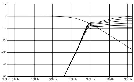
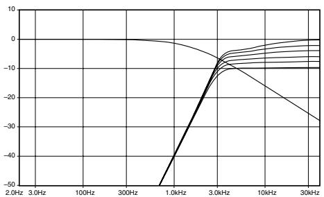
In general, this section provides precise level adjustment for optimum performance or personal taste. However, it also allows for “tilting” of the filter frequency response in order to compensate for the natural high frequency roll-off associated with off-axis listening angles. In other words, tweeter level jumper selection will have a specific effect upon both Q and cut-off frequency of each high-pass filter configuration. This effect can be seen in the filter transfer function graphs for the various system types. If the TW-HP section is set to bypass in favor of an electronic crossover, the off-axis feature will no longer function, but basic level adjustment will still be possible.
WF-LP:
In addition to functioning as a selectable low-pass filter, this section also provides part of the phase correction and response compensation of the network. By shifting the phase appropriately within the crossover region, it is possible to achieve “phase linkage” with the tweeter, producing a seamless blend or transition between the two drivers. This relationship is affected by the distance and angle of both drivers relative to the listener, but also by their proximity to each other. Since in this case, most of the manipulation of the overlapping region is being done in the tweeter high-pass filter, less variation of the woofer low-pass is necessary. Subsequently there are basically two possibilities for the LPF:
- LP1 = low Q 1^st - 2^nd order roll off (starting at 6dB/oct. ending at 9dB/oct.)
- LP2 = semi- 1^st Order (shallow 3-4dB/oct. roll off)
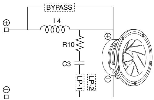
text_image
BYPASS L4 R10 C3 LP-1 LP-2$$ R 1 0 = 2. 2 \Omega $$
$$ \mathrm{C} 3 = 3 3 \mu \mathrm{F} $$
$$ \mathrm{L} 4 = 0. 3 9 \mathrm{mH} $$
SIGNAL LINK:
The signal link jumpers provide a parallel connection between the input sides of the two terminal blocks, allowing a single input connection to be made without the use of extra terminals or wiring.
Caution:
These jumpers must be removed when used in a bi-amp configuration to prevent possible damage to amplifiers.
System Type 1
System Description
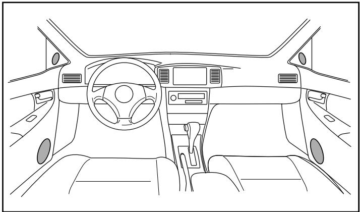
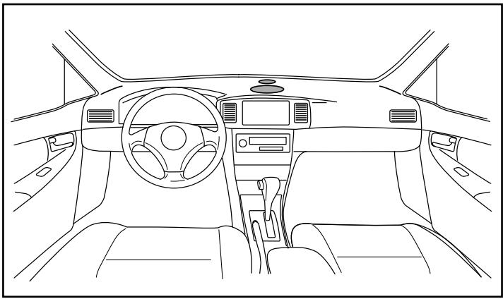
In this system type, the woofer and tweeter are mounted close together. While the kick panel is one of the more common locations to achieve this, it is certainly not the only one. What is most significant, is that by mounting the two drivers in close proximity with a minimized off-axis angle at the greatest distance possible from the listening position, it provides one of the best arrangements for optimum imaging in the vehicle. Since there are varying degrees of axis and pathlength that will be achievable for each driver in typical installations, four basic configurations are provided to accommodate the most common cases.
- Type-1A is the default setting of the network, and assumes essentially on-axis positioning with equal pathlength of both woofer and tweeter to the listening position.
- Type-1A (Option) is as above, but provides a more shallow roll-off and lower Q for the tweeter high-pass filter as an alternative.
natural_image
Front view line drawing of a car dashboard and steering wheel (no text or symbols)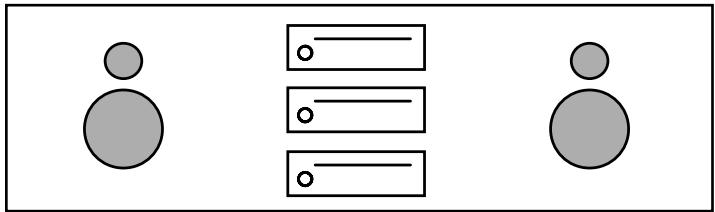
natural_image
Simple diagram with three circles and horizontal lines, no text or symbols present- Type-1B is optimized for installations where build out for better on-axis positioning is possible, and the tweeter is mounted vertical over the woofer.
natural_image
Front view line drawing of a car dashboard and steering wheel (no text or symbols)- Type-1C is for particular cases where flat to the surface mounting is required, and the tweeter is mounted over the woofer necessitating some delay for proper alignment of the two drivers.
natural_image
Front view line drawing of a car dashboard and steering wheel (no text or symbols)Network Jumper Setting
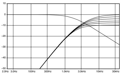
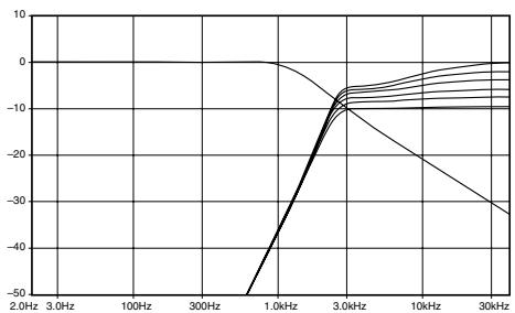
Type-1A: Pathlength to the listening position is considered to be equal in this case, with relative on-axis positioning of both drivers. Phase linkage accomplished with a relatively high Q 3 ^rd Order high-pass filter on the tweeter, resulting in a 12dB/oct. roll-off at the starting point that steepens to 18dB/oct. below 2kHz. The woofer low-pass is a semi-1 ^st Order with a very gradual slope of 3-4dB/oct. As a result, the acoustic crossover point between the two drivers is 2.8kHz.
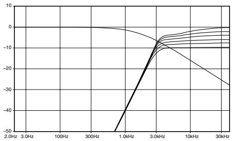
line
| Frequency | Value | | --------- | ----- | | 2.0Hz | 0 | | 3.0Hz | 0 | | 100Hz | 0 | | 300Hz | 0 | | 1.0kHz | -50 | | 3.0kHz | -10 | | 10kHz | -20 | | 30kHz | -30 |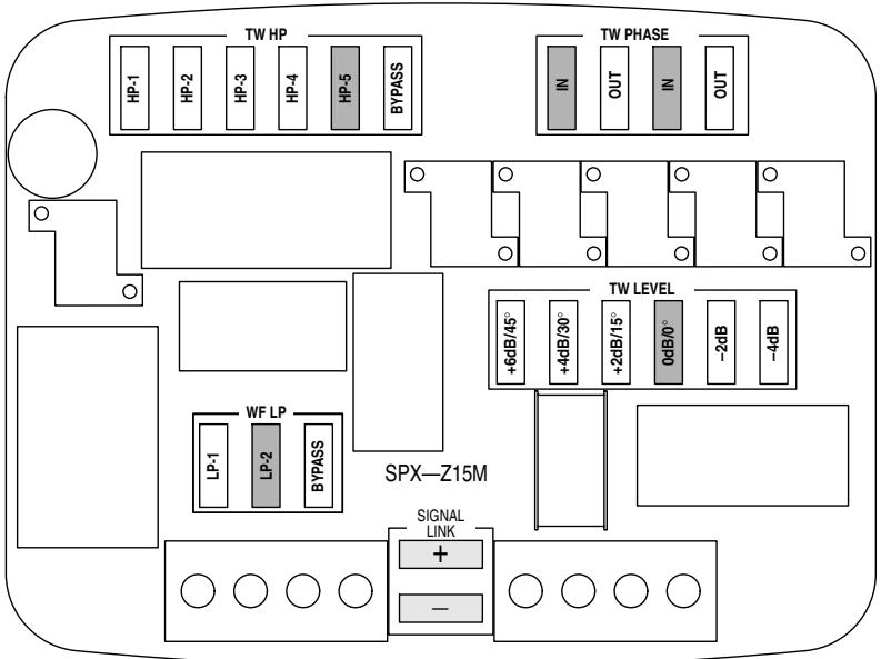
text_image
TW HP HP-1 HP-2 HP-3 HP-4 HP-5 BYPASS TW PHASE IN OUT IN OUT +6dB/45° +4dB/30° +2dB/15° 0dB/0° -2dB -4dB TPW LEVEL LP-1 LP-2 BYPASS SPX—Z15M SIGNAL LINK + - ○ ○ ○ ○ ○ ○ ○ ○Notes:
- Highlighted tweeter level jumpers are the recommended settings for each configuration, but some user adjustment may be desirable.
- Transfer function simulations only illustrate the effect of the filter upon the input signal, and therefore do not represent the actual frequency response of the system.
- If separate channels of amplification are used (bi-wire mode), the appropriate signal link jumpers must be removed.
Network Jumper Setting
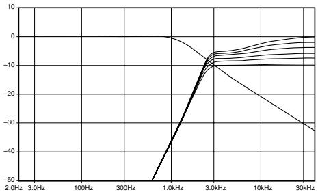
Type-1A (option): While the mounting configuration is the same as Type-1A, this network setting provides a variation for particular cases where either personal taste or vehicle acoustics requires a more gradual slope on the tweeter. In this case, the tweeter high-pass is a very low Q 2 ^nd Order, with a roll-off starting at 6dB/oct. and ending at 12dB/oct. To achieve phase linkage between the two drivers, the tweeter phase is inverted by reversing its physical connection within the network. Essentially, the parallel coil eliminates the influence of the resonance frequency, and the tweeter rolls off 12dB/oct. below 1kHz. The woofer low-pass is a semi-1 ^st Order with a very gradual slope of 3-4dB/oct. The resultant acoustic crossover point between the two drivers is 2.2kHz.
line
| Frequency | Value | | --------- | ----- | | 2.0Hz | -50 | | 3.0Hz | -40 | | 100Hz | -20 | | 300Hz | -10 | | 1.0kHz | -5 | | 3.0kHz | 0 | | 10kHz | -5 | | 30kHz | -10 |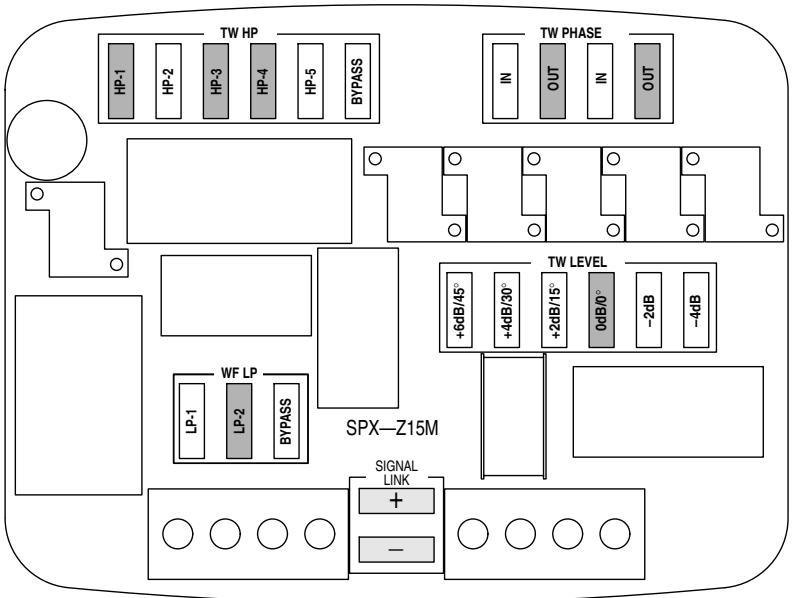
text_image
TW HP HP-1 HP-2 HP-3 HP-4 HP-5 BYPASS TW PHASE IN OUT IN OUT +6dB/45° +4dB/30° +2dB/15° 0dB/0° -2dB -4dB TPW LEVEL LP-1 LP-2 BYPASS SPX-Z15M SIGNAL LINK + - SPX-Z15MNotes:
- Highlighted tweeter level jumpers are the recommended settings for each configuration, but some user adjustment may be desirable.
- Transfer function simulations only illustrate the effect of the filter upon the input signal, and therefore do not represent the actual frequency response of the system.
- If separate channels of amplification are used (bi-wire mode), the appropriate signal link jumpers must be removed.
Network Jumper Setting
Type-1B: In some cases it may be possible or desirable to mount both drivers close together with on-axis positioning, but not quite at same distance to the listening position. In general, it is assumed that the tweeter is the closer of the two, as would be the case if it is mounted over the woofer. While there will obviously be some tolerance associated with different vehicles and installation methods, this difference is considered to be approx. 12cm. Phase linkage is accomplished by inverting the tweeter and using a slightly lower Q 3 ^rd Order high-pass than in Type-1A, combined with a low Q quasi-2 ^nd Order low-pass on the woofer. This results in an acoustic crossover point of 2.2kHz.
line
| Frequency | Value | | --------- | ----- | | 2.0Hz | -50 | | 3.0Hz | -30 | | 100Hz | -10 | | 300Hz | 0 | | 1.0kHz | -10 | | 3.0kHz | -10 | | 10kHz | -20 | | 30kHz | -30 |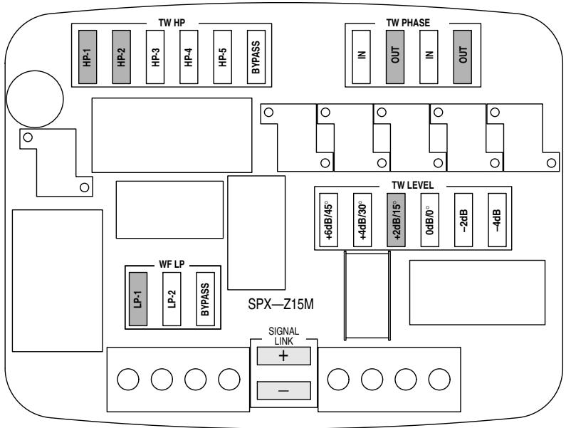
text_image
TW HP HP-1 HP-2 HP-3 HP-4 HP-5 BYPASS TW PHASE IN OUT IN OUT +6dB/45° +4dB/30° +2dB/15° 0dB/0° -2dB -4dB TPW LEVEL SPX—Z15M LP-1 LP-2 BYPASS SIGNAL LINK + - SPX—Z15MNotes:
- Highlighted tweeter level jumpers are the recommended settings for each configuration, but some user adjustment may be desirable.
- Transfer function simulations only illustrate the effect of the filter upon the input signal, and therefore do not represent the actual frequency response of the system.
- If separate channels of amplification are used (bi-wire mode), the appropriate signal link jumpers must be removed.
Network Jumper Setting
Type-1C: Even if close proximity of the two drivers can be achieved, it may not be possible to build out the mounting angles for on-axis or equidistant positioning relative to the listening position. In this particular case, both drivers are considered to be mounted basically flat to the panel, with the tweeter located over the woofer. This situation results in a relative delay of the woofer by approx. 10cm. For phase linkage in the crossover region, it is then desirable to minimize the phase shift on the woofer, and then match that to a somewhat moderate phase shift on the tweeter. This is achieved by applying a very shallow semi- 1^st order low pass on the woofer, and a relatively low Q 3^rd Order high-pass with inverted connection on the tweeter. The resultant acoustic crossover point between the two drivers is 2.15kHz.
line
| Frequency | Value | | --------- | ----- | | 2.0Hz | 0 | | 3.0Hz | 0 | | 100Hz | 0 | | 300Hz | 0 | | 1.0kHz | -10 | | 3.0kHz | -10 | | 10kHz | -20 | | 30kHz | -30 |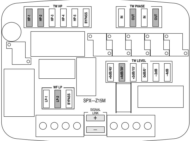
text_image
TW HP TW PHASE HP-1 HP-2 HP-3 HP-4 HP-5 BYPASS IN OUT IN OUT LP-1 LP-2 BYPASS SPX-Z15M +6dB/45° +4dB/30° +2dB/15° 0dB/0° -2dB -4dB + Signal LINK + - SPX-Z15MNotes:
- Highlighted tweeter level jumpers are the recommended settings for each configuration, but some user adjustment may be desirable.
- Transfer function simulations only illustrate the effect of the filter upon the input signal, and therefore do not represent the actual frequency response of the system.
- If separate channels of amplification are used (bi-wire mode), the appropriate signal link jumpers must be removed.
System Description
In this system type, both the woofer and tweeter are mounted apart at different distances and angles relative to the listening position, with the tweeter as the closest driver. While this type of installation is undoubtedly the most common today, some may not consider it to be an ideal situation for imaging due to the large difference in distance. In general though, a high tweeter location is thought to be advantageous for improving perceived height and width of the soundstage, as well as achieving a strong high frequency output level. In typical OEM woofer locations, the woofer is nearly always at an extreme listening angle, while the tweeter is only slightly off-axis. The woofer axis becomes more extreme the farther away it is, if there is no build out of the mounting angle. It just so happens that the same high-pass and low-pass configurations work for the two most typical installation types, only requiring a slight change in tweeter level to more properly match woofer output. It is important to note that the tuning of the settings below considers the best balance between driver and passenger listening positions, so all distances and angles are referenced to the nearest side.
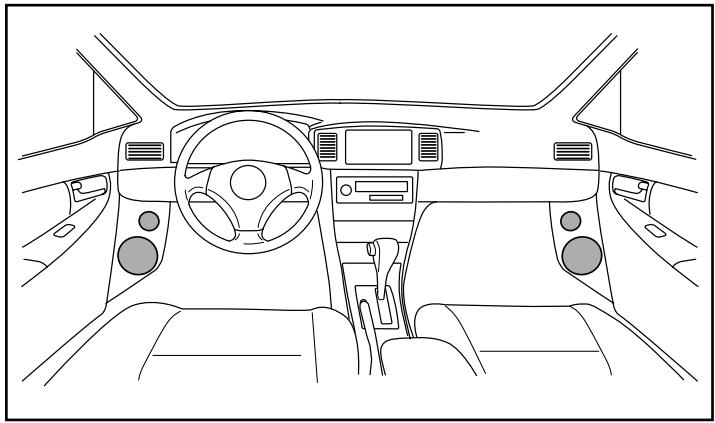
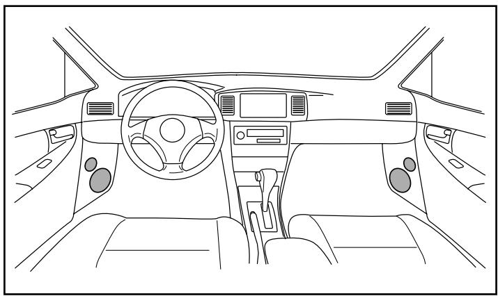
- Type-2A is considered to be the most common installation type, as the woofer is typically mounted low in the door in the factory position.
natural_image
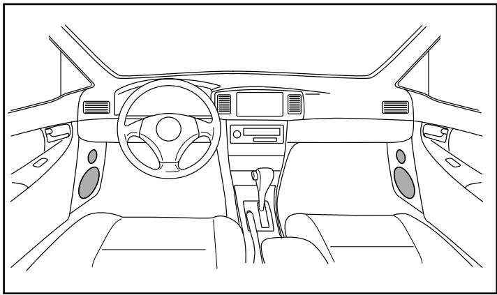
Line drawing of a car interior showing dashboard, steering wheel, and dashboard (no text or symbols)- Type-2B is essentially the same as above, but assumes the woofer somewhat farther away than is typical. This will accommodate different vehicle types as well as kick panel mounting of the woofer.
natural_image
Front view line drawing of a car interior showing dashboard, steering wheel, and seatbelt (no text or symbols)Network Jumper Setting
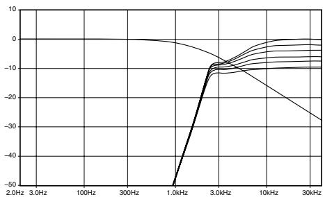
Type-2A: For the tweeter in this case, pathlength from the listening position is considered to be 85cm, at approximately 10-15° off-axis. Due to the low door location however, the listening angle for the woofer is close to 50° off-axis, resulting in a relative delay of 18cm. Therefore, minimal delay in the woofer is achieved by employing a semi-1 ^st Order 3dB/oct. low-pass. This integrates well with a steep 4 ^th Order high-pass on the tweeter, for a resultant acoustic crossover point of 2.15kHz.
line
| Frequency | Value | | --------- | ----- | | 2.0Hz | 0 | | 3.0Hz | 0 | | 100Hz | 0 | | 300Hz | 0 | | 1.0kHz | -50 | | 3.0kHz | -10 | | 10kHz | -20 | | 30kHz | -30 |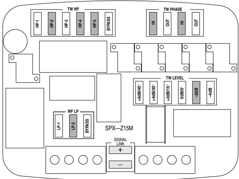
text_image
TW HP HP-1 HP-2 HP-3 HP-4 HP-5 BYPASS TW PHASE IN OUT IN OUT +6dB/45° +4dB/30° +2dB/15° 0dB/0° -2dB -4dB TPW LEVEL LP-1 LP-2 BYPASS SPX-Z15M SIGNAL LINK + - ○ ○ ○ ○ ○ ○ ○ ○Notes:
- Highlighted tweeter level jumpers are the recommended settings for each configuration, but some user adjustment may be desirable.
- Transfer function simulations only illustrate the effect of the filter upon the input signal, and therefore do not represent the actual frequency response of the system.
- If separate channels of amplification are used (bi-wire mode), the appropriate signal link jumpers must be removed.
Network Jumper Setting
Type-2B: Tweeter distance and angle are the same as above, but the woofer is located farther forward. This results in a woofer listening angle of approximately 70^ off-axis, with a relative delay of 36cm. Again, minimal delay in the woofer is achieved by employing a semi- 1^st Order 3dB/oct. low-pass, which still integrates nicely with a 4^th Order high-pass on the tweeter as long as some additional level attenuation is applied. The resultant acoustic crossover point is 2.05kHz.
line
| Frequency | Value | | --------- | ----- | | 2.0Hz | 0 | | 3.0Hz | 0 | | 100Hz | 0 | | 300Hz | 0 | | 1.0kHz | -50 | | 3.0kHz | -10 | | 10kHz | -15 | | 30kHz | -25 |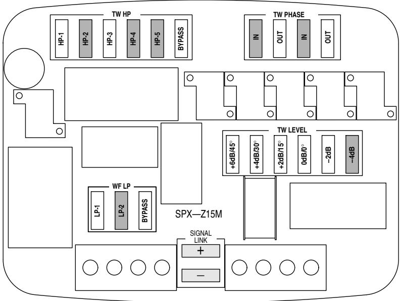
- Highlighted tweeter level jumpers are the recommended settings for each configuration, but some user adjustment may be desirable.
- Transfer function simulations only illustrate the effect of the filter upon the input signal, and therefore do not represent the actual frequency response of the system.
- If separate channels of amplification are used (bi-wire mode), the appropriate signal link jumpers must be removed.
System Type 3
System Description
In this system type, the woofer and tweeter are mounted close together on the dashboard, rear deck, or other surface that presents an oblique angle to the listener. In the particular case of center channel usage, customized mounting is almost always necessary. It should be noted that since it is impossible to anticipate every conceivable installation style, some experimentation may be necessary beyond the recommended settings. In rear deck or similar applications, the network tuning considers the best balance between driver and passenger listening positions, so all distances and angles are referenced to the nearest side.
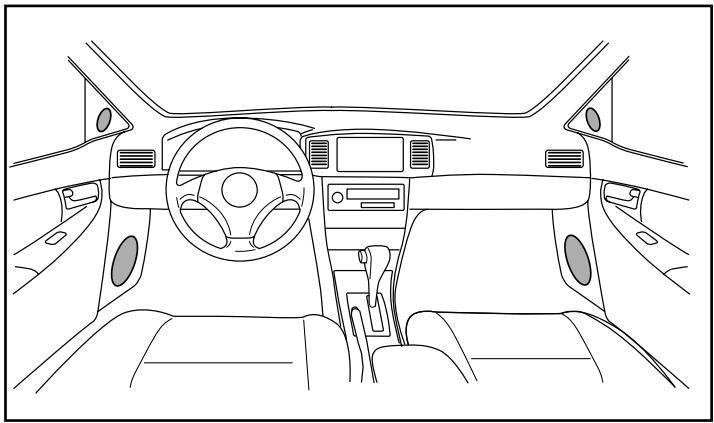
- Type-3A is considered to be a fairly close and central location with a sloping surface, resulting in an off-axis condition of both drivers relative to the listener. Additionally, due to the vertical configuration, the tweeter is the farthest of the two.
natural_image
Line drawing of a car interior view showing dashboard, steering wheel, and dashboard controls (no text or symbols)- Type-3B assumes mounting on a flat surface at some distance, with both drivers approximately equidistant relative to the listening position. The significant difference from Type-3A is that the pathlengths of each driver are essentially equal, and the flat surface presents a more extreme listening angle.
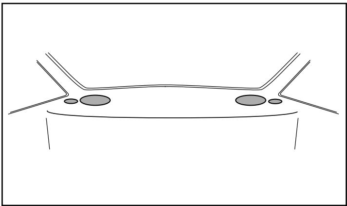
natural_image
Simple line drawing of a vehicle or car body with two side brackets and two circular features on the front (no text or symbols)Network Jumper Setting
Type-3A: Despite the fact that both drivers are mounted in the same plane and in close proximity, their orientation results in the acoustic center of the tweeter being farther away. Both drivers are considered to be 45^ off-axis at an average distance of approximately 1 meter. In this case, a medium Q 3^rd Order high-pass filter is employed in conjunction with an inverted connection to the tweeter. Proper integration between the two is then achieved with a low Q quasi- 2^nd Order low-pass on the woofer, resulting in an acoustic crossover point of 2.2kHz.
line
| Frequency | Value | | --------- | ----- | | 2.0Hz | 0 | | 3.0Hz | 0 | | 100Hz | 0 | | 300Hz | 0 | | 1.0kHz | -10 | | 3.0kHz | -10 | | 10kHz | -20 | | 30kHz | -30 |
text_image
TW HP BYPASS IN OUT IN OUT TW PHASE +6dB/45° +4dB/30° +2dB/15° 0dB/0° -2dB -4dB SPX—Z15M LP-1 LP-2 BYPASS WF LP SIGNAL LINK + - SPX—Z15MNotes:
- Highlighted tweeter level jumpers are the recommended settings for each configuration, but some user adjustment may be desirable.
- Transfer function simulations only illustrate the effect of the filter upon the input signal, and therefore do not represent the actual frequency response of the system.
- If separate channels of amplification are used (bi-wire mode), the appropriate signal link jumpers must be removed.
Network Jumper Setting
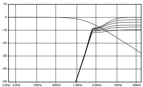
Type-3B: In positions where the component set is farther away on a flat surface, the listening angle becomes quite extreme. In this case, the mounting position is considered to present an approximate angle of 60-70° off-axis angle, at a distance of 1.2 meters to both drivers relative to the listener. Phase linkage is accomplished with a relatively high Q 3 ^rd Order high-pass filter on the tweeter, resulting in a 12dB/oct. roll-off at the starting point that steepens to 18dB/oct. below 2kHz. The woofer low pass is a semi-1 ^st Order with a very gradual slope of 3-4dB/ oct. As a result, the acoustic crossover point between the two drivers is 2.3kHz.
line
| Frequency | Value | | --------- | ----- | | 2.0Hz | 0 | | 3.0Hz | 0 | | 100Hz | 0 | | 300Hz | 0 | | 1.0kHz | -50 | | 3.0kHz | -10 | | 10kHz | -20 | | 30kHz | -30 |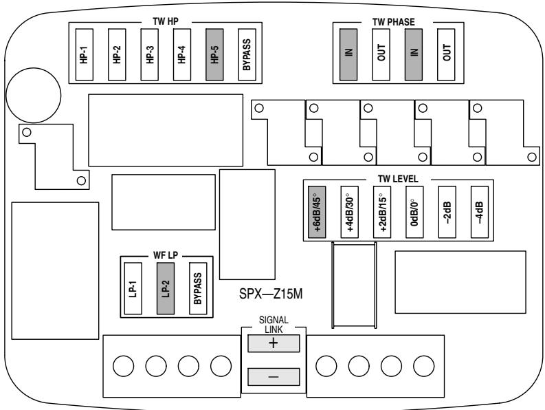
text_image
TW HP HP-1 HP-2 HP-3 HP-4 HP-5 BYPASS TW PHASE IN OUT IN OUT +6dB/45° +4dB/30° +2dB/15° 0dB/0° -2dB -4dB TW LEVEL LP-1 LP-2 BYPASS SPX—Z15M SIGNAL LINK + - ○ ○ ○ ○ ○ ○ ○ ○Notes:
- Highlighted tweeter level jumpers are the recommended settings for each configuration, but some user adjustment may be desirable.
- Transfer function simulations only illustrate the effect of the filter upon the input signal, and therefore do not represent the actual frequency response of the system.
- If separate channels of amplification are used (bi-wire mode), the appropriate signal link jumpers must be removed.
System Type 4
System Description
In this system type, some level of external signal processing is available, allowing use of the network in a partially active mode. Although speakers may be mounted in a wide variety locations in this case, it is recommended that traditional techniques be used regarding both positioning and placement.
Fully active systems have often been considered to be the most flexible, but they are certainly not the most effective or practical in all cases. While it is usually considered best to have individual channels of amplification for each driver, it may not always be appropriate to use the electronic crossover that is included with many amplifiers today. This can be especially true for systems where optimum placement or tuning is not possible, as it may be advantageous to use this network for its various phase correction and response compensation capabilities. Additionally, digital time correction can be a complimentary solution to correct for left/right seating position bias, while leaving the network in place to achieve phase linkage between the woofer and tweeter. The only situation where the network might not be used at all, is in a fully active system with individual channels of amplification, equalization and time correction available for each driver.
There are essentially three ways to use the network in a partially active mode:
1) Use all functions of the network appropriate for the installation type, but engage an electronic high-pass on the woofer for increased power handling (usually recommended in systems with subwoofers).
2) If only a limited number of channels or coarse adjustment of digital time correction is available, use it to compensate for basic left/right seating position bias while using the appropriate network setting to achieve phase linkage between individual drivers.
3) Bypass either the high-pass or low-pass section of the network in favor of an electronic crossover, still utilizing the phase and response adjustments of the other.
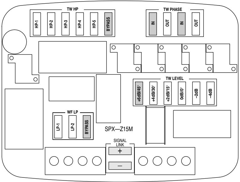
text_image
TW HP HP-1 HP-2 HP-3 HP-4 HP-5 BYPASS TW PHASE IN OUT IN OUT +6dB/45° +4dB/30° +2dB/15° 0dB/0° -2dB -4dB SPX—Z15M LP-1 LP-2 BYPASS SIGNAL LINK + - WP LEVELNote:
- The +6dB/45° setting in the TW LEVEL jumper group bypasses all resistors in the tweeter section.
- If separate channels of amplification are used (bi-wire mode), the appropriate signal link jumpers must be removed.
text_image
BYPASS 6dB/45° C1 C2 R1 4dB/30° R2 2dB/15° R3 0dB/0° R4 -2dB R5 -4dB HP-1 HP-4 L1 L2 L3 OUT + - N Z +$$ R 1 = 1, 0 \Omega $$
$$ \mathrm{R} 2 = 2, 2 \Omega $$
$$ \mathrm{R} 3 = 3, 9 \Omega $$
$$ \mathrm{R} 4 = 5, 6 \Omega $$
$$ \mathsf {R 5} = 8, 2 \Omega $$
$$ \mathrm{C} 1 = 4, 7 \mu \mathrm{F} $$
$$ \mathrm{C} 2 = 1 2 \mu \mathrm{F} $$
$$ \mathrm{L} 1 = 0, 1 7 \mathrm{mH} $$
$$ \mathrm{L} 2 = 0, 2 4 \mathrm{mH} $$
$$ \mathrm{L} 3 = 0, 5 2 \mathrm{mH} $$
1 ^er Ordre:
- Sans cavaliers HP
- HP1 + HP4
2ème Ordre:
- HP1 + HP2 + HP3 + HP4
- HP1 + HP2 + HP3 + HP4 + HP5
- HP1 + HP2 + HP4
- HP1 + HP3 + HP4
- HP1 + HP4 + HP5
- HP2 + HP3 + HP4
- HP2 + HP4
- HP3 + HP4
3ème Ordre:
- HP1 + HP2
- HP1 + HP3
- HP1 + HP2 + HP3
- HP1 + HP2 + HP3 + HP5
- HP1 + HP2 + HP5
4ème Ordre:
- HP2 + HP4 + HP5
- HP3 + HP4 + HP5
- HP2 + HP4 + HP5
- HP3 + HP4 + HP5
TW PHASE:
natural_image
Front view line drawing of a car dashboard and steering wheel (no text or symbols)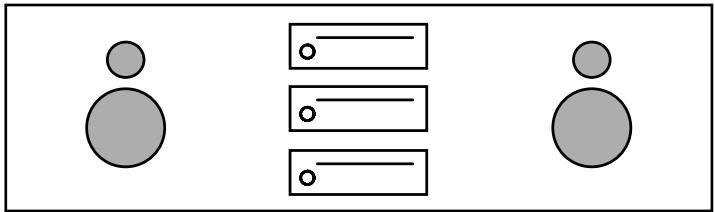
natural_image
Simple diagram with three circles and horizontal lines, no text or symbols presentnatural_image
Front view line drawing of a car dashboard and steering wheel (no text or symbols)natural_image
Front view line drawing of a car dashboard and steering wheel (no text or symbols)natural_image
Line drawing of a car interior view showing dashboard, steering wheel, and dashboard (no text or symbols)natural_image
Line drawing of a car interior view showing dashboard, steering wheel, and seat area (no text or symbols)natural_image
Line drawing of a car interior view showing dashboard, steering wheel, and dashboard controls (no text or symbols)natural_image
Simple line drawing of a symmetrical abstract shape with two curved lines and two small circles, no text or symbols present.Specifications/Spécifications
System
| Type | Component 2-way speaker |
| Power Handling (peak/RMS) | 200/50W |
| Impedance | 4 Ω |
| Frequency Response | 45-60 kHz |
| Net Weight | 3.2 kg |
| Drivers | Woofer | Tweeter |
| General | ||
| Speaker size | 5-1/2"(15cm) | 1-1/2"(39mm) |
| Power Handling (RMS) | 50W | 40W(>5kHz) |
| Voice Coil Impedance (nom) | 4 Ω | 4 Ω |
| Frequency Response (-10dB) | 10kHz | 60kHz |
| Sensitivity (@ 2.83V/ 1m) | 87dB | 94.5dB |
| Voice Coil Diameter | 38mm | 25mm |
| Linear Excursion (Xmax) | ± 6.5mm | ± 0.2mm |
| Mechanical Excursion (p- p) | ± 11mm | ± 1.6mm |
| Mechanical | ||
| Frame Material | Aluminium | Aluminium |
| Magnetic Material | Strontium | Neodymium |
| Diaphragm Material | Wood Fiber | Textile |
| Diaphragm Shape | Cross-Cut | Ring Radiator |
| Surround Material and Type | Low Loss Rubber | |
| Speaker Weight | 1300g | 400g |
| Magnet Weight | 400g | 80g |
| Magnet System Type | Symmetric Drive | |
| Depth | 69.2mm | 25.1mm |
| Cut- out diameter | 127mm | 76mm |
| Thiele/ Small | ||
| ReDC | 3.5ohm | 3.0 ohm |
| Fs | 44 Hz | 520 Hz |
| Qts | 0.48 | 0.32 |
| Qms | 2.6 | 2.29 |
| Qes | 0.59 | 0.38 |
| Vas | 12 ltr. | 14 ml |
| Sd | 95 cm2 | 5.6cm2 |
| Le | 0.27 mH | 0.01 mH |
| Cms | 0.95 mm/N | 0.3 mm/N |
| Mms | 14 g | 0.3 g |
| BI | 4.8 Tm | 2.8 Tm |
| Sealed box | ||
| Recommended Volume (Butterworth) | 10ltr. |
ALPINE ELECTRONICS MARKETING, INC.
1-1-8 Nishi Gotanda,
Shinagawa-ku, Tokyo 141-0031, Japan
Phone 03-5496-8231
ALPINE ELECTRONICS OF AMERICA, INC.
19145 Gramercy Place, Torrance, California 90501, U.S.A.
Phone 1-800-ALPINE-1 (1-800-257-4631)
ALPINE ELECTRONICS OF CANADA, INC.
7300 Warden Ave., Suite 203, Markham, Ontario L3R 9Z6, Canada
Phone 1-800-ALPINE-1 (1-800-257-4631)
ALPINE ELECTRONICS OF AUSTRALIA PTY. LTD.
6-8 Fifeways Boulevarde Keysborough,
Victoria 3173, Australia
Phone 03-9769-0000
ALPINE ELECTRONICS GmbH
Kreuzerkamp 7, 40878 Ratingen, Germany
Phone 02102-4550
ALPINE ELECTRONICS OF U.K. LTD.
Alpine House
Fletchamstead Highway,
Coventry CV4 9TW, U.K.
Phone 0870-33 33 763
ALPINE ELECTRONICS FRANCE S.A.R.L.
(RCS PONTOISE B 338 101 280)
98, Rue de la Belle Etoile, Z.I. Paris
Nord II, B.P. 50016, 95945 Roissy
Charles de Gaulle Cedex, France
Phone 01-48638989