040-026 - Milling machine Meec Tools - Free user manual and instructions
Find the device manual for free 040-026 Meec Tools in PDF.


| Product Type | Milling Machine |
| Brand | Meec Tools |
| Model | 040-026 |
| Dimensions (L x W x H) | 500 mm x 400 mm x 300 mm |
| Weight | 25 kg |
| Power Supply | 230 V / 50 Hz |
| Motor Power | 1500 W |
| Spindle Speed Range | 0 - 3000 RPM (variable) |
| Chuck Size | 13 mm (1/2 inch) |
| Table Size | 300 mm x 200 mm |
| Travel (X/Y/Z) | 150 / 100 / 80 mm |
| Functions | Milling, drilling, slotting, contouring |
| Safety Features | Emergency stop button, spindle guard, overload protection |
| Included Accessories | Milling cutter set, collet set, work light |
| Material | Cast iron body, steel table |
| Base Hole Pattern | 4 x 10 mm holes |
| Maximum Tool Diameter | 16 mm |
| Lubrication | Oil nipples for spindle and ways |
| Recommended Maintenance | Clean chips regularly, lubricate ways weekly |
| Spare Parts Availability | Contact Meec Tools spare parts service |
| Warranty | 2 years |
Frequently Asked Questions - 040-026 Meec Tools
User questions about 040-026 Meec Tools
0 question about this device. Answer the ones you know or ask your own.
Ask a new question about this device
Download the instructions for your Milling machine in PDF format for free! Find your manual 040-026 - Meec Tools and take your electronic device back in hand. On this page are published all the documents necessary for the use of your device. 040-026 by Meec Tools.
USER MANUAL 040-026 Meec Tools

natural_image
Industrial machine with control panel and mounting bracket (no visible text or symbols)EN - Operating instructions in original
Date of production: 2013-12-20
© Jula AB
SVENSKA....5
SÄKERHETSANVISNINGAR....5
TEKNISKA DATA....6
MONTERING 6
VAL AV FRÄSSTÅL....6
HANDHAVANDE 7
FÖRE FÖRSTA ANVÄNDNING....7
MATNINGSRIKTNING....7
DAMMUTSUGNING MED EXTERN ANORDNING 7
INSTÄLLNING AV VARVTAL 8
NORSK 9
SIKKERHETSANVISNINGER 9
TEKNISKE DATA....10
MONTERING....10
VALG AV FRESESTÅL....10
BRUK....11
F∅R F∅RSTE GANGS BRUK 11
MATERETNING....11
ST∅VAVSUG MED EKSTERN ANORDNING 11
INNSTILLING AV TURTALL....12
POLSKI 13
ZASADY BEZPIECZEŃSTWA 13
DANE TECHNICZNE 14
MONTAŽ 15
WYBÓR FREZU 15
OBSŁUGA 15
PRZED PIERWSZYM UŻYCIEM 15
SAFETY INSTRUCTIONS....17
TECHNICAL DATA....18
ASSEMBLY....18
SELECTING BITS....18
OPERATION....19
BEFORE USING FOR THE FIRST TIME....19
DIRECTION OF FEED 19
DUST EXTRACTION WITH EXTERNAL DEVICE....19
SETTING THE SPEED 20
SÄKERHETSANVISNINGAR
natural_image
Technical line drawing of a mechanical device with labeled component 1 (no text or symbols beyond label)- Låsspak
Jula reserves the right to make changes. In the event of problems, please contact our service department. www.jula.com
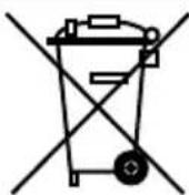

Care for the environment!
Must not be discarded with household waste!
This product contains electrical or electronic components that should be recycled.
Leave the product for recycling at the designated station e.g. the clocal authority's recycling station.
SIKKERHETSANVISNINGER
-
Håndtak
-
Spindellås
-
Spennhylse
-
Fresestål
OBS!
- Kopierhylsens bøssing
- Kopierhylse
- Arbeidsstykke
OBS!
natural_image
Technical line drawing of a mechanical device with no visible text or symbols- Låsespak
-
Turtallsinnstilling
-
Strømbryter På/Av
VEDLIKEHOLD
natural_image
Technical line drawing of a mechanical device with no visible text or symbols- Dźwignia blokująca
natural_image
Pure electrical circuit lines without any symbolsDBAJ O ŚRODOWISKO!
Read the Operating Instructions carefully before use
WARNING! Certain types of dust created during sanding, sawing, polishing, drilling and other similar work contain chemicals that can be carcinogenic, harmful to the developing foetus, or cause fertility problems. Use suitable safety equipment.
Use
- The tool is designed for machining wood and other similar materials.
- Do not use the tool to machine metal or plastic. When holding the tool it must only be used with the bit pointing down. It must not be used at an angle or pointing upwards. Contact your dealer if you want to use the tool together with a router table. Any other use is prohibited.
- Check that the mains voltage corresponds to the rated voltage on the type plate. The mains plug on the power tool must match the mains outlet.
WARNING! Unplug the power cord before cleaning, maintenance and fitting/removing parts or accessories.
SAFETY INFORMATION
NOTE! Follow all the instructions and safety instructions. Failure to follow all the instructions and safety instructions can lead to the risk of personal injury and/or material damage. The term “power tool” in all the warnings below refers to your mains-powered (corded) or battery-powered (cordless) power tool.
- Read these instructions carefully before use and save them for future reference.
- These instructions must be handed on with the tool if you sell it or pass it on. The tool must only be used by adults who have read through these instructions.
- The tool is not intended to be used by persons (children or adults) with any form of functional disorder or by persons who do not have sufficient experience or know-how on how to use it, in so far as they have not received instructions concerning the use of the tool from someone who is responsible for their safety. Children must be supervised to make sure they do not play with the tool.
Safety instructions for the work area
- Keep the work area clean and well lit. Dark and cluttered work areas increase the risk of accidents and injuries.
- Do not use power tools in explosive environments, such as in the vicinity of flammable liquids, gases or dust. Power tools produce sparks that can ignite dust and fumes.
- Keep onlookers and children at a safe distance. You can easily lose control of the equipment if you are distracted.
General safety instructions
- The mains plug on the power tool must match the mains outlet. Never modify the plug in any way. Never use adapter plugs with earthed appliances.
- Avoid body contact with earthed surfaces such as pipes, radiators, cookers and refrigerators. There is an increased risk of electric shock if your body is earthed.
- Do not expose the tool to rain or damp conditions. There is an increased risk of electric shock if water enters a power tool.
- Only use the tool for its intended purpose. Never use the cord to carry or pull the tool, or to pull out the plug from the mains socket. Keep the power cord away from heat, oil, sharp edges and moving parts. Damaged or tangled cords increase the risk of electric shock.
- If using the tool outdoors, only use an extension cord approved for outdoor use. Protect against the risk of electric shock.
- The tool must be connected to the mains via a residual current device if used in damp areas.
Personal safety
- Pay attention to what you are doing at all times, and use your common sense. Never use power tools if you are tired or under the influence of drugs, alcohol or medication. A moment of inattention when using a power tool can result in serious personal injury.
- Wear safety glasses. Depending on the type of power tool and how it is used, safety equipment such as dust masks, non-slip safety shoes, safety helmets and ear protection reduce the risk of personal injury.
- Make sure the power switch is in the OFF position before plugging in the cord and/or the battery, or lifting/carrying the tool. Carrying a power tool with your finger on the switch, or connecting a tool to the mains supply when the switch is in the ON position, increases the risk of accidents and injuries.
- Remove adjuster keys/spanners and other assembling tools before starting the power tool. Spanners or keys etc. left in a rotating part of the power tool can cause personal injury.
- Avoid unstable and awkward positions when working. Always maintain a firm footing and good balance. This will ensure you have better control over the tool in unexpected situations.
- Wear suitable clothing. Do not wear loose-fitting clothing or jewellery. Keep hair, clothing and gloves away from moving parts. Loose-fitting clothing, jewellery and long hair can get caught in moving parts.
- If dust extraction and dust collection equipment is provided, this should be connected and used correctly. The use of such devices can reduce the risk of dust-related hazards.
Use and handling
- Do not force the power tool. Always use the correct tool for the job.
- Do not use the tool if it cannot be switched on and off using the power switch. Power tools that cannot be controlled with the power switch are dangerous and must be repaired.
- Unplug the power cord and/or disconnect the battery before making any adjustments, changing accessories or putting the power tool away.
- Store power tools out of the reach of children when not in use. Individuals must not use the tool
unless they are familiar with these instructions. Power tools are dangerous if used by inexperienced people.
- Keep the power tool properly maintained. Make sure that moving parts are properly adjusted and do not jam and that no parts are incorrectly fitted or damaged. Check for any other factors that could influence functionality. If the power tool is damaged, it must be repaired before being used again. Many accidents are caused by poorly maintained power tools.
- Keep cutting tools sharp and clean for better, safer work. Properly maintained cutting tools with sharp cutting edges are less likely to jam and are easier to control.
- Use power tools, accessories, bits, etc., in accordance with these instructions, taking into account actual working conditions and the work that is to be done. Use the power tool only for its intended purpose.
WARNING
- Follow the safety instructions when working with power tools to safeguard against the risk of fire, electric shock and personal injury.
- Wear safety glasses. Wear a dust filter mask. Wear ear protection.
- Secure the workpiece with a clamp, vice or clips.
- Never use router bits that are warped, deformed or damaged in some other way. Only use bits with a shank diameter of 6 or 8 mm, which can withstand the maximum speed of the tool.
- Never use blunt bits.
- Only use bits intended for wood and other similar materials.
- Make sure the workpiece is free of nails and foreign objects.
- Allow the motor to reach full speed before milling. Never start the tool when the bit is in contact with the workpiece.
- Do not press the tool forwards too hard. Smooth forward movements reduce the risk of problems and will ensure the tool lasts longer.
- For best results, work anticlockwise when working with outer contours and clockwise when working with inner contours.
• Machine in several stages when using large diameter bits, or when machining a lot of material.
- Switch off and unplug the tool immediately in the event of abnormal noise or abnormal vibrations.
- Do not put the tool down until it has completely stopped.
- Switch off the tool, unplug the power cord and wait until all moving parts have stopped completely before carrying out any cleaning and/or maintenance. Unplug the power cord when the tool is not in use.
- Switch off the tool, unplug the power cord and wait until all moving parts have stopped completely before attempting to remove cuttings or bits etc.
- The tool is only intended for machining wood and other similar materials.
Before use
- Always check before use that the tool, power cord and plug, including any accessories, are undamaged.
- Do not use the tool if it is damaged.
• Always check that all the parts are correctly fitted before use. - Make sure the power switch is in the OFF position before plugging the plug into the mains supply.
- Check that the mains voltage corresponds to the rated voltage on the type plate. The mains plug on the power tool must match the mains outlet.
- The tool must only be connected to an earthed mains socket.
WARNING! If the power cord or plug are damaged, they must be replaced by authorised service personnel to ensure safe use.
Maintenance
The power tool must only be serviced by qualified service personnel using identical spare parts. This will ensure that the power tool remains safe to use.
TECHNICAL DATA
| Rated voltage 230 V ~ 50 Hz | |
| Output | 1020 W |
| Speed (no load) 11 500-34 000 rpm | |
| Collet 8 mm | |
| Sound pressure level, LpA 91 dB(A), K=3 dB | |
| Sound power level, LwA 102 dB(A), K=3 dB | |
| Vibration level 4.1 m/s ^2 , K=1.5 m/s ^2 | |
Always wear ear protection!
The declared vibration value, which has been measured by a standardised test method, can be used to compare different tools with each other and for a preliminary assessment of exposure.
WARNING! The actual vibration level when using power tools may differ from the specified maximum value, depending on how the tool is used. It is therefore necessary to determine which safety precautions are required to protect the user, based on an estimate of exposure in actual operating conditions (taking into account all stages of the work cycle, e.g. the time when the tool is switched off and when it is idling, in addition to the start-up time).
DESCRIPTION
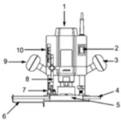
- Speed setting
- Power switch ON/OFF
- Handle
- Bar for parallel fence
- Baseplate
- Parallel fence
- Adjustable depth stop
- Depth stop
- Handle
- Depth adjustment
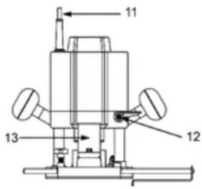
- Power cord
- Locking lever
- Dust extraction
USE
FITTING THE COLLETS AND REPLACING BITS
The tool is intended for bits with a maximum shank diameter of 8 mm. The supplied collects are used for bits with a shank diameter of 6 or 8 mm. Follow the instructions below to replace the collet.
- Release the locking lever and pull out the bit as far as it goes.
- Place the tool on a flat, non-slip surface.
- Select the bit and a suitable collet.
- Press the spindle lock and remove the clamp nut.
- Insert the collet in the spindle and hold it pressed in place.
- Screw the clamp nut on the spindle thread.
- Insert the bit at least 20 mm into the collet.
- Hold the spindle lock pressed in and firmly screw tight the collect with a spanner.
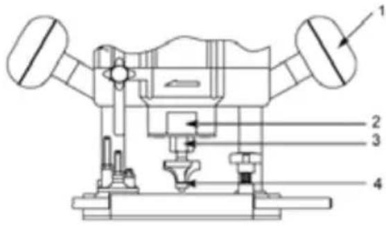
-
Handle
-
Spindle lock
-
Collet
-
Bit
NOTE
- The 8 mm collet is fitting in the spindle on delivery. The transparent cover over the dust extraction mechanism can be removed to simplify changing collets or bits. Remove the cover by removing the two clamping screws underneath the baseplate.
- You only need to slightly release the clamp nut to replace bits with the same shank diameter. It is not necessary to completely remove the clamp nut.
WARNING!
- Handle bits with care – risk of cutting yourself. Only use accessories that can withstand with the maximum speed of the tool (see technical data).
- Clean the chuck, collet and bit before fitting.
- Check that the bit and chuck are correctly fitted and rotate freely before starting the tool.
CONNECTION OF VACUUM CLEANER
- You can connect a vacuum cleaner to the dust extraction mechanism on the tool.
- The outer diameter of the dust extraction connection is approx. 38 mm, and the inner diameter is approx. 34 mm. Always use a dust extraction system to ensure a safe and clean working environment.
Handle
Screw tight the handles in the threaded holes on the sides of the tool.
USING A MACHINING TEMPLATE
The round metal template guide is used to move the tool along the required contour. The template guide bush, which has an external diameter of 19 mm, must fit to the template. The template contour is transferred to the workpiece. Follow the instructions below to fit the template guide.
- Place the tool on a flat, non-slip surface.
- Fit the required bit.
- Remove the two clamping screws from the dust extraction mechanism underneath the baseplate.
- Fit the template guide with the bush facing downwards.
- Fix the template guide with the clamping screws and the dust extraction mechanism (see diagram).
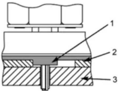
- Template guide bush
- Template guide
- Workpiece
NOTE
The template guide is only intended to be used together with templates. It must be removed before normal machining. If the dust extraction mechanism is in the way of the template guide, you can fit the template guide without the dust extraction mechanism by using the supplied M5 nuts.
Parallel fence
The parallel fence is used when milling grooves parallel to the edge of the workpiece. Fit the parallel fence on the guides. Insert the guides in the openings on the side of the baseplate and adjust the required gap between the parallel fence and the bit. Lock the guides in the baseplate with the screws.
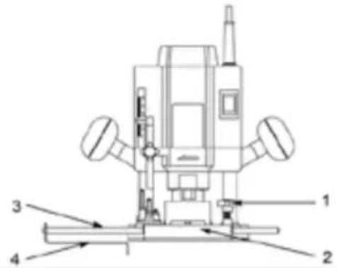
- Locking screw
- Baseplate
- Guide
- Parallel fence
Centring pin
The centring pin is used for milling circular contours. Remove the parallel fence. Clamp the centring pin on one of the guides by tightening the wing nut. Insert the guide in one of the openings on the side of the baseplate and adjust the required gap between the centring pin and the bit. Lock the guide in the baseplate with the retaining screws.
Depth stop
Adjust the depth stop by releasing the locking lever and pressing the tool handle until the required depth setting is reached. Lock the locking lever again.
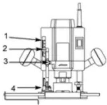
- Depth indicator
- Depth indicator with marking
- Locking screw
- Adjustable depth stop
There are seven positions on the adjustable depth stop. The depth stop means that you can set exactly the same milling depth used previously. Release the locking screw, turn the depth stop to the required depth, and lock.
NOTE
The depth stop positions must be adjusted every time you replace a bit because the bits have different lengths.
natural_image
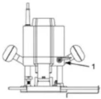
Technical line drawing of a mechanical device with no visible text or symbols- Locking lever
Release the locking lever and pull in the bit after use. Do not allow an unprotected bit to stick out under the baseplate.
Starting/Stopping
Start Press the power switch. The tool switches on when pressing the switch. The switch cannot be locked in the ON position.
Stop Release the power switch.
Setting the speed
Set the required speed from 16,000 to 30,000 rpm with the speed setting. Set a suitable speed for the bit diameter and the material to be machined.
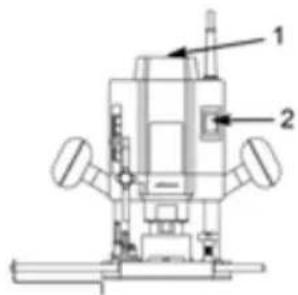
- Speed setting
- Power switch ON/OFF
MAINTENANCE
NOTE! Switch off the tool and unplug the power cord before carrying out any adjustments, replacing parts, cleaning or doing maintenance work.
Cleaning
- Clean the tool with a cloth moistened with a mild detergent. Never use strong detergents or solvents as they can damage the tool's plastic parts.
- Keep the tool vents clean.
- Keep the guides clean. Lubricate them with thin oil when necessary.
Jula reserves the right to make changes. In the event of problems, please contact our service department. www.jula.com

Care for the environment!
Must not be discarded with household waste!
This product contains electrical or electronic components that should be recycled.
Leave the product for recycling at the designated station e.g. the clocal authority's recycling station.
CE
EC DECLARATION OF CONFORMITY
EG FÖRSÄKRAN OM ÖVERENSSTÄMMELSE
EF SAMSVARSERKLÆRING
DEKLARACJA ZGODNOŚCI WE

Jula AB, Box 363, SE-532 24 SKARA, SWEDEN
Machinery Directive 2006/42/EC
EN 60745-1:2009+A11, EN 60745-2-17:2010
Electromagnetic Compatibility Directive 2004/108/EC
EN 55014-1:2006+A1, EN 55014-2:1997+A1+A2
EN 61000-3-2:2006+A1+A2, EN 61000-3-3:2008, EN 61000-3-11:2000
RoHS Directive 2011/65/EU
This product was CE marked in year -13
Name and address of the person authorised to compile the technical file:
- SVENSKA....5
- SÄKERHETSANVISNINGAR....5
- TEKNISKA DATA....6
- MONTERING 6
- VAL AV FRÄSSTÅL....6
- HANDHAVANDE 7
- FÖRE FÖRSTA ANVÄNDNING....7
- MATNINGSRIKTNING....7
- DAMMUTSUGNING MED EXTERN ANORDNING 7
- INSTÄLLNING AV VARVTAL 8
- NORSK 9
- SIKKERHETSANVISNINGER 9
- TEKNISKE DATA....10
- MONTERING....10
- VALG AV FRESESTÅL....10
- BRUK....11
- F∅R F∅RSTE GANGS BRUK 11
- MATERETNING....11
- ST∅VAVSUG MED EKSTERN ANORDNING 11
- INNSTILLING AV TURTALL....12
- POLSKI 13
- ZASADY BEZPIECZEŃSTWA 13
- DANE TECHNICZNE 14
- MONTAŽ 15
- WYBÓR FREZU 15
- OBSŁUGA 15
- PRZED PIERWSZYM UŻYCIEM 15
- SAFETY INSTRUCTIONS....17
- TECHNICAL DATA....18
- ASSEMBLY....18
- SÄKERHETSANVISNINGAR
- Care for the environment!
- SIKKERHETSANVISNINGER
- OBS!
- VEDLIKEHOLD
- DBAJ O ŚRODOWISKO!
- Read the Operating Instructions carefully before use
- Use
- SAFETY INFORMATION
- Safety instructions for the work area
- General safety instructions
- Personal safety
- Use and handling
- WARNING
- Before use
- Maintenance
- Always wear ear protection!
- DESCRIPTION
- FITTING THE COLLETS AND REPLACING BITS
- NOTE
- WARNING!
- CONNECTION OF VACUUM CLEANER
- Handle
- USING A MACHINING TEMPLATE
- Parallel fence
- Centring pin
- Depth stop
- Starting/Stopping
- Setting the speed
- Cleaning
- CE
- EC DECLARATION OF CONFORMITY
- EG FÖRSÄKRAN OM ÖVERENSSTÄMMELSE
- EF SAMSVARSERKLÆRING
- DEKLARACJA ZGODNOŚCI WE
Brand : Meec Tools
Model : 040-026
Category : Milling machine