
TD101F - Screwdriver MAKITA - Free user manual and instructions
Find the device manual for free TD101F MAKITA in PDF.


User questions about TD101F MAKITA
0 question about this device. Answer the ones you know or ask your own.
Ask a new question about this device
Download the instructions for your Screwdriver in PDF format for free! Find your manual TD101F - MAKITA and take your electronic device back in hand. On this page are published all the documents necessary for the use of your device. TD101F by MAKITA.
USER MANUAL TD101F MAKITA
Explanation of general view
-
Switch trigger
-
Fastening torque
-
Screw
-
Lamp
-
Fastening time (S)
-
Hook
-
Reversing switch lever
-
Proper fastening torque
-
Groove
-
Bit
-
High tensile bolt
-
Bumper
-
Sleeve
-
Limit mark
-
Hammer case cover
-
Bit-piece
-
Screwdriver
-
Standard bolt
-
Brush holder cap
SPECIFICATIONS
| Model | TD0101/TD0101F | |
| Capacities | Machine screw | 4 mm - 8 mm |
| Standard bolt | 5 mm - 14 mm | |
| High tensile bolt | 5 mm - 10 mm | |
| No load speed (min-1) | 0 - 3,600 | |
| Impacts per minute (min-1) | 0 - 3,200 | |
| Max. fastening torque | 100 N·m | |
| Dimensions (L x W x H) | 184 mm x 67 mm x 192 mm | |
| Net weight | 0.99 kg | |
| Safety class | 回/II | |
- Due to our continuing programme of research and development, the specifications herein are subject to change without notice.
Note: Specifications may differ from country to country.
Weight according to EPTA-Procedure 01/2003
Intended use
ENE033-1
The tool is intended for screw driving in wood, metal and plastic.
Power supply
ENF002-1
The tool should be connected only to a power supply of the same voltage as indicated on the nameplate, and can only be operated on single-phase AC supply. They are double-insulated in accordance with European Standard and can, therefore, also be used from sockets without earth wire.
SPECIFIC SAFETY RULES
GEB012-3
DO NOT let comfort or familiarity with product (gained from repeated use) replace strict adherence to impact driver safety rules. If you use this tool unsafely or incorrectly, you can suffer serious personal injury.
- Hold power tool by insulated gripping surfaces, when performing an operation where the fastener may contact hidden wiring or its own cord.
Fasteners contacting a "live" wire may make exposed metal parts of the power tool "live" and could give the operator an electric shock. - Always be sure you have a firm footing. Be sure no one is below when using the tool in high locations.
- Hold the tool firmly.
- Wear ear protectors.
SAVE THESE INSTRUCTIONS.
WARNING:
MISUSE or failure to follow the safety rules stated in this instruction manual may cause serious personal injury.
FUNCTIONAL DESCRIPTION
CAUTION:
Always be sure that the tool is switched off and unplugged before adjusting or checking function on the tool.
Switch action (Fig. 1)
CAUTION:
- Before plugging in the tool, always check to see that the switch trigger actuates properly and returns to the "OFF" position when released.
To start the tool, simply pull the switch trigger. Tool speed is increased by increasing pressure on the switch trigger. Release the switch trigger to stop.
Lighting up the lamp (Model TD0101F only) (Fig. 2)
CAUTION:
- Do not look in the light or see the source of light directly.
Connect the plug to light up the lamp. The lamp keeps on lighting while the plug is connected.
NOTE:
- Use a dry cloth to wipe the dirt off the lens of lamp. Be careful not to scratch the lens of lamp, or it may lower the illumination.
- Do not use thinner or gasoline to clean the lamp. Such solvents may damage it.
Reversing switch action (Fig. 3)
- This tool has a reversing switch to change the direction of rotation. Depress the reversing switch lever from the A side for clockwise rotation or from the B side for counterclockwise rotation.
CAUTION:
Always check the direction of rotation before operation.
- Use the reversing switch only after the tool comes to a complete stop. Changing the direction of rotation before the tool stops may damage the tool.
ASSEMBLY
CAUTION:
Always be sure that the tool is switched off and unplugged before carrying out any work on the tool.
Installing or removing driver bit or socket bit (Fig. 4)
Use only bits that has inserting portion shown in the figure.
For European and North & South American countries, Australia and New Zealand
| A=12 mm B=9 mm | Use only these type of bit. Follow the procedure (1). (Note) Bit-piece is not necessary. |
For other countries
| A=17 mm B=14 mm | To install these types of bits, follow the procedure (1). (Note) Makita bits are these types. |
| A=12 mm B=9 mm | To install these types of bits, follow the procedure (2). (Note) Bit-piece is necessary for installing the bit. |
- To install the bit, pull the sleeve in the direction of the arrow and insert the bit into the sleeve as far as it will go. Then release the sleeve to secure the bit. (Fig.5)
- To install the bit, pull the sleeve in the direction of the arrow and insert the bit-piece and bit into the sleeve as far as it will go. The bit-piece should be inserted into the sleeve with its pointed end facing in. Then release the sleeve to secure the bit. (Fig. 6)
To remove the bit, pull the sleeve in the direction of the arrow and pull the bit out firmly.
NOTE:
- If the bit is not inserted deep enough into the sleeve, the sleeve will not return to its original position and the bit will not be secured. In this case, try re-inserting the bit according to the instructions above.
OPERATION (Fig. 7)
NOTE:
- The size of wood screw which can be fastened with this tool may differ depending upon the type of material to be fastened. Always perform a test operation to determine the size of wood screw.
Holding the tool
Hold the tool only by the handle when performing an operation. Do not touch the metal part.
The proper fastening torque may differ depending upon the kind or size of the screw/bolt, the material of the workpiece to be fastened, etc. The relation between fastening torque and fastening time is shown in the figures. (Fig. 8 & 9)
Hold the tool firmly and place the point of the driver bit in the screw head. Apply forward pressure to the tool to the extent that the bit will not slip off the screw and turn the tool on to start operation.
NOTE:
- Use the proper bit for the head of the screw/bolt that you wish to use.
- When fastening screw M8 or smaller, carefully adjust pressure on the switch trigger so that the screw is not damaged.
- Hold the tool pointed straight at the screw.
- If you tighten the screw for a time longer than shown in the figures, the screw or the point of the driver bit may be overstressed, stripped, damaged, etc. Before starting your job, always perform a test operation to determine the proper fastening time for your screw.
The fastening torque is affected by a wide variety of factors including the following. After fastening, always check the torque with a torque wrench.
- Driver bit or socket bit Failure to use the correct size driver bit or socket bit will cause a reduction in the fastening torque.
2. Bolt
- Even though the torque coefficient and the class of bolt are the same, the proper fastening torque will differ according to the diameter of bolt.
-
Even though the diameters of bolts are the same, the proper fastening torque will differ according to the torque coefficient, the class of bolt and the bolt length.
-
The manner of holding the tool or the material of driving position to be fastened will affect the torque.
- Operating the tool at low speed will cause a reduction in the fastening torque.
MAINTENANCE
CAUTION:
- Always be sure that the tool is switched off and unplugged before attempting to perform inspection or maintenance.
Replacing carbon brushes (Fig. 10)
Remove and check the carbon brushes regularly. Replace when they wear down to the limit mark. Keep the carbon brushes clean and free to slip in the holders. Both carbon
brushes should be replaced at the same time. Use only identical carbon brushes.
Use a screwdriver to remove the brush holder caps. Take out the worn carbon brushes, insert the new ones and secure the brush holder caps. (Fig. 11)
To maintain product SAFETY and RELIABILITY, repairs, carbon brush inspection and replacement, any other maintenance or adjustment should be performed by Makita Authorized Service Centers, always using Makita replacement parts.
ACCESSORIES
CAUTION:
- These accessories or attachments are recommended for use with your Makita tool specified in this manual. The use of any other accessories or attachments might present a risk of injury to persons. Only use accessory or attachment for its stated purpose.
If you need any assistance for more details regarding these accessories, ask your local Makita Service Center.
Screw bits
- Socket bits
- Bit piece
- Adjustable locator with bit
- Hook
Hook (Fig. 12)
The hook is convenient for temporarily hanging the tool. This can be installed on either side of the tool.
To install the hook, insert it into a groove in the tool housing on either side and then secure it with a screw. To remove, loosen the screw and then take it out.
Adjustable locator with bit (Fig. 13)
To use the adjustable locator with bit, remove the bumper and then install it. The bumper can be removed by pulling forward.
For European countries only
Noise
ENG102-1
The typical A-weighted noise level determined according to EN60745-2-2:
Sound pressure level (L_pA) : 90 dB (A)
Sound power level L_WA) : 101 dB (A)
Uncertainty (K): 3 dB (A)
Wear ear protection
Vibration
ENG205-1
The vibration total value (tri-axial vector sum) determined according to EN60745-2-2:
Work mode: impact tightening of fasteners of the maximum capacity of the tool
Vibration emission (a_h) .. 7.5~m / s^2
Uncertainty (K): 1.5m / s^2
EC-DECLARATION OF CONFORMITY
ENH101-9
Model; TD0101, TD0101F
We declare under our sole responsibility that this product is in compliance with the following standards of standardized documents;
EN60745, EN55014, EN61000 in accordance with
Council Directives, 2004/108/EC, 98/37/EC.
CE 2008
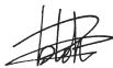
Tomoyasu Kato
Director
Responsible Manufacturer:
Makita Corporation
3-11-8, Sumiyoshi-cho, Anjo, Aichi, JAPAN
Authorized Representative in Europe:
Makita International Europe Ltd.
Michigan Drive, Tongwell, Milton Keynes, Bucks MK15 8JD, ENGLAND
FRANÇAIS
Descriptif
Fabricant responsible :
Makita Corporation
3-11-8, Sumiyoshi-cho, Anjo, Aichi, JAPON
Representant agreé en Europe :
Makita International Europe Ltd.
Michigan Drive, Tongwell, Milton Keynes, Bucks MK15
8JD, ANGLETERRE
DEUTSCH
Michigan Drive, Tongwell, Milton Keynes, Bucks MK15
8JD, ENGLAND
ITALIANO
3-11-8, Sumiyoshi-cho, Anjo, Aichi, GIAPPONE
Michigan Drive, Tongwell, Milton Keynes, Bucks MK15 8JD, INGHILTERRA
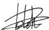
Tomoyasu Kato
Director
Michigan Drive, Tongwell, Milton Keynes, Bucks MK15 8JD, ENGELAND
Michigan Drive, Tongwell, Milton Keynes, Bucks MK15
8JD, REINO UNIDO
Descrição geral
Michigan Drive, Tongwell, Milton Keynes, Bucks MK15 8JD, INGLATERRA
Model TD0101, TD0101F
Michigan Drive, Tongwell, Milton Keynes, Bucks MK15 8JD, ENGLAND
Eviikn Iepiypaq
Ttis eupwtaikcs xwpec movo
OópuβoS
ENG102-1
To uyntheo aaiueo nntteo nxntiknc tneon tsou exi kaopotei ouuowvae EN60745-2-2:
Ooynie ts Ettipotnnc, 2004/108/EK, 98/37/EK.
CE 2008

Tomoyasu Kato
△ieuθuvtns
YTeUbvoC KataoKeuaaTns:
Makita Corporation
3-11-8, Sumiyoshi-cho, Anjo, Aichi, JAPAN
Egouaiobotnevo AvntpooawtoN Evupwn
Makita International Europe Ltd.
Michigan Drive, Tongwell, Milton Keynes, Bucks MK15 8JD, AΓΤΑΙΑ
Makita Corporation
Anjo, Aichi, Japan
884879-992