
T737 HD - AV receiver NAD - Free user manual and instructions
Find the device manual for free T737 HD NAD in PDF.
| Product type | Audio-video receiver |
| Brand | NAD |
| Model | T737 HD |
| Dimensions (W x H x D) | 435 x 167 x 394 mm |
| Net weight | 12.08 kg |
| Power supply | 120 V 60 Hz or 230 V 50 Hz depending on version |
| Standby power consumption | Less than 1 W |
| Idle power consumption | 46 W |
| Output power (stereo mode) | 2 x 80 W (8 Ω, 0.08% THD) |
| Output power (surround mode) | 7 x 40 W |
| Frequency response | ±0.5 dB (20 Hz - 20 kHz) |
| Signal-to-noise ratio (A-weighted) | >100 dB (ref. nominal power 8 Ω) |
| Digital audio inputs | 2 optical, 1 coaxial, 1 front optical |
| HDMI inputs | 2 inputs, 1 output (monitor) |
| Component video inputs | 3 inputs, 1 output |
| Analog audio inputs | 6 pairs (including 7.1 multichannel) |
| Preamp subwoofer output | 1 (SUBW PRE-OUT) |
| Speaker connectors | 7 pairs (screw terminals, accepts banana plugs) |
| Built-in radio tuner | AM/FM, option XM (120V) or DAB (230V) |
| Cleaning | Dry cloth only |
| Maintenance and safety | Do not expose to water or heat sources; maintain ventilation of at least 10 cm on sides and rear, 50 cm above |
| Repairability | Entrust any repairs to qualified personnel |
| Spare parts | Contact an authorized NAD dealer |
| Included accessories | AVR 3 remote control, AM and FM antenna, power cord |
Frequently Asked Questions - T737 HD NAD
User questions about T737 HD NAD
0 question about this device. Answer the ones you know or ask your own.
Ask a new question about this device
Download the instructions for your AV receiver in PDF format for free! Find your manual T737 HD - NAD and take your electronic device back in hand. On this page are published all the documents necessary for the use of your device. T737 HD by NAD.
USER MANUAL T737 HD NAD
TO REDUCE THE RISK OF FIRE OR ELECTRIC SHOCK, DO NOT EXPOSE THIS PRODUCT TO RAIN OR MOISTURE.
SAVE THESE INSTRUCTIONS FOR LATER USE. FOLLOW ALL WARNINGS AND INSTRUCTIONS MARKED ON THE EQUIPMENT.
1 Read these instructions.
2 Keep these instructions.
3 Heed all warnings.
4 Follow all instructions.
5 Do not use this apparatus near water.
6 Clean only with a dry cloth.
7 Do not block any of the ventilation openings. Install in accordance with the manufacturer's instructions.
8 Do not install near any heat sources such as radiators, heat registers, stoves, or other apparatus (including amplifiers) that produce heat.
9 Do not defeat the safety purpose of the polarized or grounding type plug. A polarized plug has two blades with one wider than the other. A grounding type plug has two blades and a third grounding prong. The wide blade or the third prong is provided for your safety. When the provided plug does not fit into your outlet, consult an electrician for replacement of the obsolete outlet.
10 Protect the power cord from being walked on or pinched particularly at plugs, convenience receptacles, and the point where they exit from the apparatus.
11 Only use the attachments/accessories specified by the manufacturer.
12 Use only with a cart, stand, tripod, bracket, or table specified by the manufacturer, or sold with the apparatus. When a cart is used, use caution when moving the cart/apparatus combination to avoid injury from tip-over.
13 Unplug this apparatus during lightning storms or when unused for long periods of time.
14 Refer all servicing to qualified service personnel. Servicing is required when the apparatus has been damaged in any way, such as power supply cord or plug is damaged, liquid has been spilled or objects have fallen into the apparatus, the apparatus has been exposed to rain or moisture, does not operate normally, or has been dropped.
NOTE TO CATV SYSTEM INSTALLER
This reminder is provided to call the CATV system installer's attention to Section 820-40 of the NEC which provides guidelines for proper grounding and, in particular, specifies that the cable ground shall be connected to the grounding system of the building, as close to the point of cable entry as practical.
FCC NOTICE
This equipment has been tested and found to comply with the limits for a Class B digital device, pursuant to part 15 of the FCC Rules. These limits are designed to provide reasonable protection against harmful interference in a residential installation.
This equipment generates uses and can radiate radio frequency energy and if not installed and used in accordance with the instructions, may cause harmful interference to radio communications. However, there is no guarantee that interference will not occur in a particular installation. If this equipment does cause harmful interference to radio or television reception, which can be determined by turning the equipment off and on, the user is encouraged to try to correct the interference by one or more of the following measures
Reorient or relocate the receiving antenna.
- Increase the separation between the equipment and receiver.
- Connect the equipment into an outlet on a circuit different from that to which the receiver is connected
- Consult the dealer or an experienced radio/TV technician for help.
WARNING!
The unit must not be exposed to dripping or splashing liquids, and liquid-filled objects such as vases or cups should not be placed on the unit.
CAUTION
Changes or modifications to this equipment not expressly approved by NAD Electronics for compliance could void the user's authority to operate this equipment.
CAUTION
These servicing instructions are for use by qualified service personnel only. To reduce the risk of electric shock, do not perform any servicing other than that contained in the operating instructions unless you are qualified to do so.
ATTENTION
Disconnect this apparatus from the AC mains completely by unplugging the power cord plug from the AC receptacle.
CAUTION REGARDING PLACEMENT
To maintain proper ventilation, be sure to leave a space around the unit (from the largest outer dimensions including projections) that is equal to or greater than shown below.
Left and Right Panels: 10 cm
Rear Panel: 10 cm
Top Panel: 50 cm
NOTES ON ENVIRONMENTAL PROTECTION

At the end of its useful life, this product must not be disposed of with regular household waste but must be returned to a collection point for the recycling of electrical and electronic equipment. The symbol on the product, user's manual and packaging, point this out.
The materials can be reused in accordance with their markings. Through re-use, recycling of raw materials or other forms of recycling of old products, you are making an important contribution to the protection of our environment. Your local administrative office can advise you of the responsible waste disposal point.
INFORMATION ABOUT COLLECTION AND DISPOSAL OF WASTE BATTERIES (DIRECTIVE 2006/66/EC OF THE EUROPEAN PARLIAMENT AND THE COUNCIL OF EUROPEAN UNION) (FOR EUROPEAN CUSTOMERS ONLY)

Pb
Batteries bearing any of these symbols indicate that they should be treated as "separate collection" and not as municipal waste. It is encouraged that necessary measures are implemented to maximize the separate collection of waste batteries and to minimize the disposal of batteries as mixed municipal waste.

Hg
Cd
End-users are exhorted not to dispose waste batteries as unsorted municipal waste. In order
to achieve a high level of recycling waste batteries, discard waste batteries separately and properly through an accessible collection point in your vicinity. For more information about collection and recycling of waste batteries, please contact your local municipality, your waste disposal service or the point of sale where you purchased the items.
By ensuring compliance and conformance to proper disposal of waste batteries, potential hazardous effects on human health is prevented and the negative impact of batteries and waste batteries on the environment is minimized, thus contributing to the protection, preservation and quality improvement of the environment.
NOTE: THE T 737 IS NOT AN AUTO VOLTAGE UNIT. CONNECT ONLY TO THE PRESCRIBED AC OUTLET, I.E., 120V 60HZ OR 230V 50HZ.
RECORD YOUR MODEL NUMBER (NOW,WHILE YOU CAN SEE IT)
The model and serial number of your new T 737 are located on the back of the cabinet. For your future convenience, we suggest that you record these numbers here:
Model no:
Serial no:
TABLE OF CONTENTS
IMPORTANT SAFETY INSTRUCTIONS 2
INTRODUCTION
GETTING STARTED 5
WHAT'S IN THE BOX .5
CHOOSING A LOCATION .5
DEFAULT SOURCE SETTINGS .5
IDENTIFICATION OF CONTROLS
FRONT PANEL. 6
REAR PANEL .8
AVR 3 REMOTE CONTROL 11
USING THE AVR 3 REMOTE CONTROL. 11
LIBRARY. 14
OPERATION
USING THE T 737 - MAIN MENU. 15
ABOUT THE ON-SCREEN DISPLAY (OSD). 15
MAIN MENU. 15
LISTENING MODE. 15
ADJUSTING LISTENING MODES. 16
TONE CONTROLS. 17
USING THE T 737-SETUP MENU. 18
SETUP MENU. 18
SOURCE SETUP . 18
SOURCE SETUP (NORMAL VIEW) . 18
SWITCHING OF VIDEO SYSTEM (FOR 230V VERSION MODEL ONLY). 19
SOURCE SETUP (TABLE VIEW). 20
iPod SETUP . 20
SPEAKER SETUP . 20
SPEAKER CONFIGURATION . 20
SPEAKER LEVELS. 21
SPEAKER DISTANCE. 22
ADJUSTING THE VOLUME . 22
TRIGGER SETUP 22
LISTENING MODE SETUP 22
LISTENING MODES 23
DOLBY SETUP 24
DTS SETUP 24
ENHANCED STEREO. 24
DISPLAY SETUP 25
A/V PRESETS SETUP 25
LISTENING TO AM/FM RADIO 26
ABOUT USER NAMES 27
ABOUT RDS 27
LISTENING TO XM RADIO 28
LISTENING TO DAB RADIO 29
CONNECTING THE DAB MODULE 29
DAB OPERATION 29
SERVICE LIST 29
DAB TUNER MODE 29
LOCAL SCAN 29
PRESET TUNE 30
STATION ORDER 30
DYNAMIC RANGE. 30
MANUAL SCAN. 30
PRUNE LIST. 30
INFORMATION SETTINGS. 31
LISTENING TO YOUR iPod PLAYER 32
CONNECTING THE OPTIONAL "NAD IPD 1 DOCK FOR 32
iPod" AND iPod PLAYER TO THE T 737 32
iPod MENU OPTIONS 32
CONTROL FEATURES 32
REFERENCE
TROUBLESHOOTING 34
SPECIFICATIONS 35
THANK YOU FOR CHOOSING NAD.
The T 737 A/V Receiver is a technologically advanced and highly capable product — yet we have invested great effort in making it simple and easy to use. The T 737 delivers a range of genuinely useful options for surround sound and stereo listening, using powerful digital signal processing and superbly accurate digital-audio circuitry. However, we have also been careful to ensure that the T 737 is as musically transparent and spatially accurate as possible, incorporating much of what we've learned from a quarter century's experience designing audio, video and home-theater components. As with all our products, NAD's "Music First" design philosophy guided the T 737's design, such that it can confidently promise you both state-of-the-art surround home-theater and audiophile-quality music listening for years to come.
We encourage you to take a few minutes now to read right through this manual. Investing a little time here at the outset might save you a good deal of time later, and is by far the best way to ensure that you make the most of your investment in the NADT 737, and get the most from this powerful and flexible home-theater component.
One more thing: We urge you to register your T 737 ownership on the NAD Worldwide Web site:
http://NADelectronics.com/warranty
For warranty information contact your local distributor.
WHAT'S IN THE BOX
Packed with your T 737 you will find
An AM loop antenna
A FM lead-type antenna
A detachable AC power cord
The AVR 3 remote control with two AA batteries.
This owner's manual.
SAVE THE PACKAGING
Please save the box and all of the packaging in which your T 737 arrived. Should you move or otherwise need to transport your T 737, this is by far the safest container in which to do so. We've seen too many otherwise perfect components damaged in transit for lack of a proper shipping carton, so please: Save that box!
CHOOSING A LOCATION
Choose a location that is well ventilated (with at least several inches to both sides and behind), and that will provide a clear line of sight, within 23 feet/7 meters, between the T 737's front panel and your primary listening/viewing position—this will ensure reliable infrared remote control communications. The T 737 generates a modest amount of heat, but nothing that should trouble adjacent components.
It is especially important that sufficient ventilation be provided. If you are contemplating on locating the T 737 within a cabinet or other furniture, consult your NAD audio/video specialist for advice on providing adequate airflow.
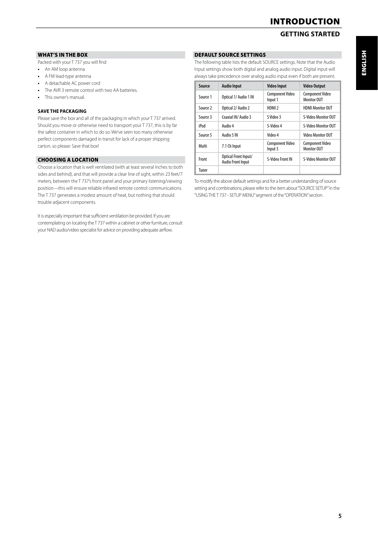
DEFAULT SOURCE SETTINGS
The following table lists the default SOURCE settings. Note that the Audio Input settings show both digital and analog audio input. Digital input will always take precedence over analog audio input even if both are present.
| Source | Audio Input | Video Input | Video Output |
| Source 1 | Optical 1/ Audio 1 IN | Component Video Input 1 | Component Video Monitor OUT |
| Source 2 | Optical 2/ Audio 2 | HDMI 2 | HDMI Monitor OUT |
| Source 3 | Coaxial IN/ Audio 3 | S Video 3 | S-Video Monitor OUT |
| iPod | Audio 4 | S-Video 4 | S-Video Monitor OUT |
| Source 5 | Audio 5 IN | Video 4 | Video Monitor OUT |
| Multi | 7.1 Ch Input | Component Video Input 3 | Component Video Monitor OUT |
| Front | Optical Front Input/ Audio Front Input | S-Video Front IN | S-Video Monitor OUT |
| Tuner |
To modify the above default settings and for a better understanding of source setting and combinations, please refer to the item about "SOURCE SETUP" in the "USING THE 737 - SETUP MENU" segment of the "OPERATION" section.
FRONT PANEL
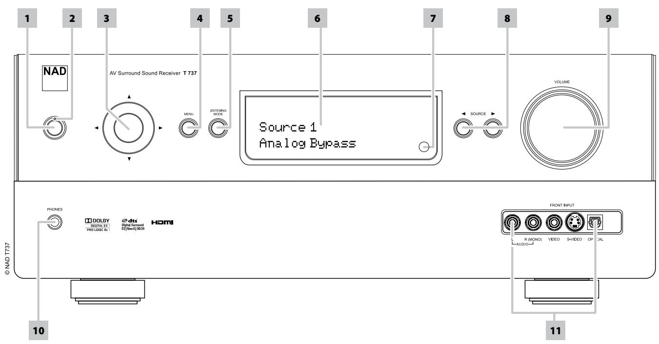
1 POWER BUTTON: Press this button to switch ON the T 737. The Standby LED indicator will turn from amber to blue and illuminate the VFD. Pressing the power button again turns the unit back to standby mode.
2 STANDBY LED: This indicator will light up amber when the T 737 is in standby state. When the T 737 is in the ON state, this indicator will illuminate blue.
3 NAVIGATION and ENTER buttons: These buttons are used to navigate the T 737 OSD as well as for navigation of DAB (230V version only), XM (120V version only) tuner functions and iPod. The middle round button is designated as "ENTER" button; this is normally pressed to complete a selection, procedure, sequence or other applicable functions.
4 MENU: When listening to DAB (230V version only) or XM (120V version only) radio, press this button to enable their corresponding digital radio menu in conjunction with the applicable [//] and [ENTER] buttons.
5 LISTENING MODE: Toggle to select through the various Listening mode options. Depending on the format of the currently selected input (digital or analog, stereo or multichannel), various listening modes are available. Refer also to the item about LISTENING MODE under the USING THE T 737 - MAIN MENU segment of the OPERATION section.
6 VACUUM FLUORESCENT DISPLAY (VFD): Displays visual information about the current settings like the active Source, volume level, listening mode, audio format, applicable RDS/XM/DAB as well as iPod-related display information and other related indicators. Refer also to the item about DISPLAY SETUP under the USING THE T 737 - SETUP MENU segment of the OPERATION section.
7 REMOTE SENSOR: Point the AVR 3 remote control at the remote sensor and press the buttons. Do not expose the remote sensor of the T 737 to a strong light source such as direct sunlight or illumination. If you do so, you may not be able to operate the T 737 with the remote control.
Distance: About 23ft (7m) from the front of the remote sensor. Angle: About 30^ in each direction of the front of the remote sensor.
8 SOURCE [ / ] : Press these buttons to toggle through the input selections - Source 1, Source 2, Source 3, iPod, Source 5, Multi Front and Tuner (AM/FM/XM/DAB as applicable). More Sources could be directly recalled through these buttons upon enabling them at the Setup Menu. Refer also to the item about SOURCE SETUP under the USING THE T 737 - SETUP MENU segment of the OPERATION section.
9 VOLUME: Use this control to adjust the volume level of the speakers. Turn clockwise to increase the volume setting; counter clockwise to lower it. Refer also to the item about ADJUSTING THE VOLUME under the USING THE T 737 - SETUP MENU segment of the OPERATION section.
10 PHONES: Accepts stereo headphone using a standard 1/4-inch stereophone plug (use a suitable adapter for headphones equipped with a smaller plug). Plugging in headphones automatically mutes output from all channels. With headphone listening, toggle front panel's LISTENING MODE button (or AVR 3's [SURR] button) to select between "Dolby H/P" (Dolby Headphone) and "Dolby H/P Off" (Dolby Headphone Off).
DOLBY® HEADPHONE
Dolby Headphone technology, compatible with any pair of conventional headphones, accurately simulates the experience of hearing a 5.1-channel speaker system properly set up in a listening room, minus the annoying " listener fatigue" effect that plagues other headphone-based virtual surround sound offerings. Dolby Headphone technology is ideal for private playback of multi-channel entertainment without disturbing others nearby.
Select Dolby HP Off for normal headphone audio listening.
11 FRONT INPUT PORTS: Use these convenience jacks for occasional sources such as a camcorder, tape player, video game console, any analog audio or optical digital audio and composite or S-Video video sources. If your source only has a single audio output jack or is marked "Mono output", plug this into the T 737's Front "R (MONO)" input. On the other hand, if your source has two output jacks indicative of stereo output, insert both jacks into the T 737's corresponding Front "L" and "R (MONO)" input to achieve stereo output as well.
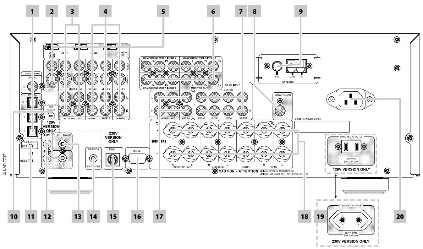
REAR PANEL
ATTENTION!
Please make sure that the T 737 is powered off or unplugged before making any connections. It is also advisable to power down or unplug all associated components while making or breaking any signal or AC power connections.
1 DIGITAL AUDIO (COAXIAL IN, OPTICAL 1-2): Connect to the corresponding optical or coaxial S/PDIF-format digital output of sources such as CD or DVD players, HDTV or satellite tuners and other components. Coaxial and Optical digital input association is configurable via the Source Setup item of the Setup Menu OSD.
DIGITAL AUDIO OPTICAL OUT: Connect the optical digital OUT port to the corresponding S/PDIF digital input of a compatible device such as CD recorders, receivers, computer soundcard or other digital processors.
2 MONITOR (S-VIDEO,VIDEO): Connect to video input of the monitor/ television using quality dual-RCA and/or S-Video cables designed for video signals. In general, the S-Video connection is superior and should be used if your TV/monitor provides the corresponding input.
3 AUDIO 1 IN/OUT,VIDEO 1/S-VIDEO 1 IN/OUT: Connect the T 737's AUDIO 1 OUT/VIDEO 1 OUT/S-VIDEO 1 OUT jacks to the analog audio/video input of a recording component such as a cassette deck, DVD recorder or to an outboard audio/video processor. Connect the T 737's AUDIO 1 IN/VIDEO 1 IN/S-VIDEO 1 IN jacks to the component's corresponding output.
The signal present at these AUDIO 1 OUT/VIDEO 1 OUT/S-VIDEO 1 OUT jacks are determined by the source last selected via the front panel SOURCE buttons or the AVR 3's input select buttons. There will be no output at AUDIO 1 OUT/VIDEO 1 OUT/S-VIDEO 1 OUT port when Source 1 is the selected source input. This prevents feedback through the recording component thereby preventing possible damage to your speakers.
4 AUDIO 2-4/VIDEO 2-4/S-VIDEO 2-4: These comprise the T 737's other principal inputs. Connect these S-Video, composite video, and analog stereo audio input ports to the corresponding output ports of source components such as DVD players and HDTV/satellite tuners. Refer also to "AUDIO 1 IN/OUT,VIDEO 1/S-VIDEO 1 IN/OUT" discussion above.
AUDIO 4 IN and S-VIDEO IN 4 are also the assigned default ports for the audio/video output of the separately sold NAD IPD (NAD Dock for iPod) 1, NAD IPD 2 and later variants.
5 HDMI (HDMI 1-2, HDMI MONITOR OUT): Connect HDMI inputs to the HDMI OUT connectors of source components such as DVD player, BD player or HDTV satellite/cable box. Connect the HDMI Monitor OUT to a HDTV or projector with HDMI input.
NOTE
The HDMI ports support transmission of video signals only. For HDMI audio signal, connect your HDMI source component's S/PDIF-format digital output signal to the applicable T 737 digital audio input ports. You can then correspondingly assign this HDMI digital audio input as your particular HDMI 1 or HDMI 2 digital audio source via the Source Setup item of the Setup Menu OSD.
WARNING
Before connecting and disconnecting any HDMI cables, both the T 737 and the ancillary source must be powered OFF and unplugged from the AC outlet. Failure to observe this practice may cause permanent damage to all equipment connected via HDMI sockets.
6 COMPONENTVIDEOINPUT1-3,COMPONENTVIDEOMONITOR
OUT: Connect the Component Video IN 1-3 inputs to Component Video outputs from compatible source components, typically a DVD player and terrestrial or satellite HDTV tuner. Connect Component Video OUT to the Component Video input of a compatible video monitor/TV. Be sure to observe consistency in connecting the Y/Pb/Pr jacks to the corresponding sources/inputs. The routing of the component video inputs is fully configurable via the Source Setup item of the Setup Menu OSD. The T 737's component video inputs and outputs are fully wideband and compatible with allowable HDTV formats.
The T 737 is optimized for Component Video Output. Composite video and S-video sources may be viewed in their native format or via Component Video Monitor OUT.
| VIDEO INPUT | VIDEO OUTPUT | ||
| Component Video Monitor OUT | S-Video Monitor OUT | Video (Composite) Monitor OUT | |
| Video (Composite) input | Yes (480i/576i only) | Yes | Yes |
| S-Video input | Yes (480i/576i only) | Yes | Yes |
| Component Video input | Yes | Yes (480i/576i only) | Yes (480i/576i only) |
7 7.1 CH INPUT: Connect to the corresponding analog audio output ports of multichannel source components such as a DVD-Audio or multichannel-SACD player or external multichannel decoder (disc copy protected formats only allow analog signal transfer). Typically, these sources will produce 5.1-channel output, in which case the Surround Back jacks are left unconnected. The signals present at these jacks may be heard by selecting Multi (7.1 Channel Input is defaulted to this Source setting).
There is no bass-management or other processing (other than master-volume control) available to this 7.1 Channel Input. While the multi-channel audio outputs of a DVD-Video player can be connected to these jacks, using the T 737's own Dolby Digital and DTS decoding and digital-analog converters via a digital connection will usually produce superior results.
8 SUBW PRE-OUT: Unlike full range channels, there is no power amplifier built-in to the T 737 for a subwoofer. Connect the SUBW PRE OUT to powered ("active") subwooers or to power amplifier channels driving a passive system.
9 FM, AM ANTENNA INPUT: Connect the supplied lead-type FM antenna to the FM antenna input. Extend the lead. Experiment freely with your antenna placement and orientation until you get the clearest sound and lowest background noise. Fix the antenna in the desired position by using thumb tacks, push pins or any suitable means.
The AM loop antenna supplied with the T 737 (or a suitable replacement) is required for AM reception. Open the clip terminal lever; insert the wire making sure to match the color-coded (white and black) ends of the wire to that of the terminal and close the lever ensuring that the lever locks the wire in place. Testing different positions for the antenna may improve reception; vertical orientation will usually produce the best results. Antenna proximity to large metal objects (appliances, radiators) may impair reception, as will attempts to lengthen the wire to the loop.
10 XM MODULE INPUT (120V version only): Connect XM radio cable to this socket. Follow the instructions that came with your XM radio. With XM radio, there are more than 100 channels of music, news, sports, comedy, talk and entertainment. You will find that the coverage is continent wide. The music quality is digital with many commercial-free music channels.
NOTE
The external XM radio is not supplied with your T 737.
11 UPGLOAD MCU, RESET: The MCU, HDMI and RESET tact switches are used for software program updates (if any) in combination with the RS232. Your custom installer or dealer can assist you in the proper upgrade and setup of your T 737.
12 IR IN/IR OUT 1, 2: These mini-jacks accept and output remote-controlled codes in electrical format, using industry-standard protocols, for use with "IR-repeater" and multi-room systems and related technologies.
IR IN: This input is connected to the output of an IR (infrared) repeater (Xantech or similar) or the IR output of another component to allow control of the T 737 from a remote location.
IR OUT 1, IR OUT 2: Both IR OUT 1 and IR OUT 2 have dual-features - they can act as an infrared command repeater or as stand alone IR OUT. Connect the T 737's IR IN to the IR OUT of ancillary equipment. Connect also the T 737's IR OUT 1 (or IR OUT 2) to another equipment with IR IN feature. With this setup, the T 737 acts as an "IR-repeater" allowing the equipment connected to the T 737's IR IN control or command of the other equipment linked to the T 737's IR OUT 1 (or IR OUT 2).
As a stand alone IR OUT, connect IR OUT 1 (or IR OUT 2) to the IR IN of an ancillary equipment. Direct the ancillary equipment's own remote control to the T 737's infrared receiver to command or control the linked unit.
13 +12V TRIGGER OUT: The +12V TRIGGER OUT is used for controlling external equipment that is equipped with a +12V trigger input. Connect this +12V TRIGGER OUT to the other equipment's corresponding +12V DC input jack using a mono cable with 3.5mm male plug. The availability of 12V at this trigger output depends upon the setting of "Trigger Out" in the TRIGGER SETUP OSD menu. See discussion about "TRIGGER SETUP" at the "SETUP MENU" literature for guidelines on how to configure "Trigger Out".
14 MP DOCK: The T 737 is equipped with a data port in the rear panel where an optional NAD IPD (NAD Dock for iPod) 1, NAD IPD 2 and later variants can be plugged in. Connect the "MP DOCK (DATA PORT)" jack of the T 737 to the corresponding "DATA PORT" socket of the optional NAD IPD model.
NOTE
The external "NAD IPD (NAD Dock for iPod)" model is not supplied with your T 737.
REAR PANEL
15 DAB MODULE INPUT (230V version only): Plug-in the other end of the Mini-Din connector from the NAD DAB Adaptor DB 1 module output port into this socket. The T 737 is compatible only with NAD DAB Adaptor DB 1 so check with your NAD dealer for this module's availability. With DAB, you can receive CD-like quality programs without any annoying interference and signal distortion.
NOTE
The external "NAD DAB Adaptor DB 1 module" is not supplied with your T737.
16 RS-232: Connect this interface via RS-232 serial cable (not supplied) to any Windows® compatible PC to allow remote control of the T 737 through NAD's proprietary PC software or other compatible external controllers. NAD is a certified partner of AMX and Crestron and fully supports these external devices. See your NAD audio specialist for more information.
17 AUDIO 5 IN/OUT, AUDIO 6: Input for additional line level input signals such as CD player, MP player or a tape recorder. Connect AUDIO 5 OUT to the analog audio input of a recording component such as a cassette deck, DVD recorder or to an outboard audio/video processor. Connect the AUDIO 5 IN jacks to the component's corresponding output. AUDIO 6 is ideal for the connection of the analog output of line-level audio sources like a CD player or Stereo tuner.
18 SPEAKERS: Connect the respective speaker's FRONT L, FRONT R, CENTER, SURROUND R, SURROUND L, SURROUND BACK L, SURROUND BACK R and CENTER channels to their corresponding loudspeakers. Make sure the "+" (red) terminal and "-" (black) terminal are connected to the corresponding "+" and "-" terminals of the loudspeaker. Use extra care to ensure that no stray wires or strands cross between posts or terminals at either end.
The T 737 is designed to produce optimum sound quality when connected to speakers with impedances within its operating range. Please make sure that all the speakers are rated 8 ohms minimum per speaker.
NOTE
Use stranded wire of at least 16 gauge (AWG). Connections to the T 737 can be made with banana plugs (120 V version model only) or by using bare wire or pins.
19 SWITCHED AC OUTLET: This convenience outlet can supply switched power to another component or accessory. It is powered ON and OFF by the front panel POWER button or by the AVR 3's ON and OFF keys.
The total draw of all devices connected to this outlet must not exceed 50 watts.
20 AC MAINS INPUT: The T 737 comes supplied with a separate AC Mains cable. Before connecting the cable to a live wall socket, ensure that it is firmly connected to the T 737's AC Mains input socket first. Connect only to the prescribed AC outlet, i.e., 120V60Hz (for 120V version models of T 737 only) or 230V50Hz (for 230V version models of T 737 only). Always disconnect the AC Mains cable plug from the live wall socket first, before disconnecting the cable from the T 737's Mains input socket.
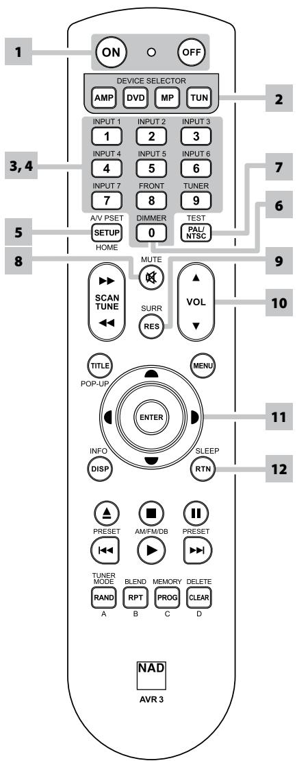
USING THE AVR 3 REMOTE CONTROL
The AVR 3 remote control handset handles the key functions of the T 737 as well as other NAD Stereo Receivers, Integrated Amplifiers and Preamplifiers. It has additional controls to remotely operate NAD CD Players, AM/FM Tuners and dedicated AM/FM/DAB Tuners. It will operate up to a distance of 23ft (7m). Alkaline batteries are recommended for maximum operating life. Two AA batteries should be fitted in the battery compartment at the rear of the Remote Control handset. When replacing batteries, check that they have been put in the right way round, as indicated on the base of the battery compartment.
When a command from the remote control is received, the Standby LED indicator will blink. Note that the indicator may also blink when receiving commands not necessarily for the T 737 but for other components in the system. Please refer to previous sections of the manual for a full description of individual functions.
NOTE
The remote control handset supplied with the T 737 is of a universal NAD type, designed to operate several NAD models. Some buttons are applicable only to specific NAD models. Contact your dealer or NAD audio specialist for assistance.
1 POWER ON & OFF: The AVR 3 remote has a separate ON and OFF button. Press the ON button to switch the unit from Standby to operating mode. Press the OFF button to switch the unit to Standby mode.
2 DEVICE SELECTOR: A Device Selector button determines only what component the AVR 3 will command; it does not perform any function on the receiver. Press desired Device Selector button for the applicable buttons to be directed to a "page" of commands relevant to the selected device. Upon selecting a Device, you can now press the corresponding AVR 3 control buttons applicable for the selected Device.
3 INPUT SELECTORS: Refer to the corresponding labels printed in the remote control faceplate and their respective assigned buttons to make use of these functions. Set the DEVICE SELECTOR to "AMP" in order to gain access to these buttons. The input selector buttons perform the same functions as the buttons labeled the same on the front panel.
NOTE
INPUT 1, INPUT 2 up to INPUT 6 correspond to the T737's SOURCE 1, SOURCE 2 up to SOURCE 6.
INPUT 7 corresponds to MULTI. These inputs or sources will have to be enabled for them to be directly recalled or accessed.
4 NUMERIC KEYS: The numeric keys allow for direct input of tracks for CD players and direct channel/preset access for tuners and receivers.
5 A/V PSET: In combination with the numeric keys, press a Preset number from 1 to 5. Note that the Preset settings can be configured via the A/V PRESETS SETUP menu.
6 DIMMER (for use with NAD Stereo Receiver, Tuner and CD Player): Reduce, turn off or restore VFD brightness. Depending on the NAD model, the brightness of the front panel display will vary when you toggle this button.
7 TEST: Press to initiate speaker TEST mode while at "Speaker Levels" line item under "Speaker Setup" menu.
8 MUTE: Press the [MUTE] button to temporarily switch OFF the sound to the speakers and headphones. MUTE mode is indicated by the Standby LED indicator flashing for NAD Integrated Amplifiers or "Mute" shown in the VFD of NAD Receivers. Press MUTE again to restore sound. Adjusting the volume level via the AVR 3 or the front panel volume knob will automatically release the mute function.
9 SURR: Toggle to select desired listening or surround mode.
AVR 3 REMOTE CONTROL
10 VOL [ / ] : Press [ / ] button to increase or decrease the loudness level. Release the button when the desired level is reached. The VFD on the front panel will indicate the level set. For NAD Receivers, the VFD will also show "Volume Up," "Volume Down" or "Volume: _ dB" ( _ indicates the numerical dB level) while pressing AVR 3's.
11 [ / / ] :Select an item in a menu.
12 SLEEP: Switch off the NAD Receiver or Tuner after a preset number of minutes.
SLEEP MODE
The Sleep Mode timer will switch the T 737 to Standby mode automatically after a preset number of minutes. Pressing the AVR 3's [SLEEP] button once will display the setting of the sleep time increment. Pressing the AVR 3's [SLEEP] button a second time within a 3-second period will change the sleep time increment in 15-minute intervals, after which time the T 737 will automatically switch into Standby mode.
To adjust the sleep delay, press the AVR 3's [SLEEP] button twice; first to display the sleep time increment, and a second time to change the sleep time increment. The sleep time increment will continuously be displayed on the T 737's front panel Vacuum Fluorescent Display (VFD). Each consecutive press increases the sleep time in 15-minute increments from 15 to 90 minutes. To cancel the sleep mode, continue pressing the AVR 3's [SLEEP] button until "Sleep Off" is displayed on the VFD. Switching the T 737 to standby from either the AVR 3's OFF or the T 737's Power button will also cancel the sleep mode.
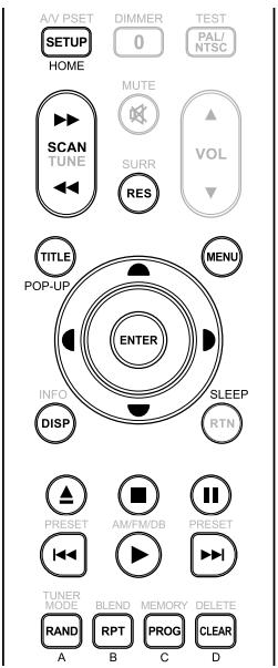
DVD/BD/CD PLAYER CONTROL (for use with NAD CD Player, Blu-ray Disc Player or DVD
Player): Set the DEVICE SELECTOR to "DVD" in order to gain access to these buttons. Some of the control buttons below are applicable only to specific NAD CD Player, Blu-ray Disc Player or DVD Player models; check the owner's manual of your NAD model for control button compatibility. You can also load the applicable NAD code library to this device so that it can be made compatible with your other NAD equipment. Refer to the section below about "LIBRARY" on how to load a NAD code library.
HOME: Display or exit HOME menu.
TITLE/POP-UP: Display DVD title menu or BD-ROM pop menu, if available.
MENU: Access menu on a DVD disc, if available.
SCAN[</>>]:Fast reverse/forward search.
[△]: Open or close disc tray.
[■]: Stop playback.
[II]: Pause playback temporarily.
[▶▶]: Go the next track, file or chapter.
[1]: Go to the beginning of current/previous track, file or chapter.
[▶]: Start playback.
ENTER: Select desired track, folder or WMA/MP3 file.
DISP: Show playback time and other display information.
RAND: Play tracks/files in random order.
RPT: Repeat track, file or whole disc.
PROG: Enter or exit program mode.
CLEAR: Delete programmed track/file.
RES: Set output resolution of HDMI and Component Video output.
SETUP: Access or remove setup menu.
A,B,C,D: Navigate or select BD-ROM menu, if applicable; Page up/down PHOTO and MUSIC menu list.
TUNER CONTROL (for use with NAD Receiver, AM/FM/DAB Tuner): Set the DEVICE SELECTOR to "TUN" in order to gain access to these buttons. Refer to the corresponding labels printed in the remote control faceplate and their respective assigned buttons to make use of these functions. Some of the control buttons below are applicable only to specific NAD Receiver or Tuner models; check the owner's manual of your NAD Receiver or Tuner for control button compatibility. You can also load the applicable NAD code library to this device so that it can be made compatible with your other NAD equipment. Refer to the section below about "LIBRARY" on how to load a NAD code library.
TUNE [</▶] or [</▶]: Step up or down between AM or FM frequencies.
PRESET [▶/▶] or [▲/▼]: Step up or down between stored radio resets.
AM/FM/DB: Select DAB, XM, FM or AM band (if applicable).
TUNER MODE: In FM mode, toggle between "FM Mute On" and "FM Mute Off". In DAB mode, pressing this button will bring up DAB menu options.
BLEND: Engage or disengage BLEND feature.
MEMORY: Save current station into preset memory.
DELETE: Press and hold for about 2 seconds and the selected preset memory is erased.
[←/▶]: In DAB mode, in combination with TUNER MODE or other compatible buttons, toggle to select through DAB feature options like Dynamic Range Control, Station Order and other appropriate DAB options.
ENTER: In AM/FM mode, toggle to select Preset or Tune mode. In DAB mode, press and hold to check signal strength.
INFO: Repeatedly pressing this button will show information as supplied by the current radio station. The applicable display contents include related DAB display information and RDS broadcast data.

NOTE
For iPod player-specific control buttons, please refer to "CONTROL FEATURES" under "OPERATION - LISTENING TO YOUR iPod PLAYER".
AVR 3 REMOTE CONTROL
LIBRARY
The AVR 3 can store a different library of default NAD codes for each of its DEVICE SELECTOR "pages." If the original default library does not control your NAD CD player, DVD player, or other component, follow the procedure below to change the library code. Refer as well to the table below for a list applicable NAD Library Codes with their corresponding NAD models.
LOAD ANOTHER LIBRARY CODE
Example: Load NAD DVD Player T 517 library codes to AVR 3's "DVD" device.
1 Press and hold [DVD] in the DEVICE SELECTOR section of AVR 3.
2 While holding down the device button (DVD), press "2" and "2" using AVR 3's numeric buttons. "22" is the corresponding library code for T 517.
3 Press [ENTER] while still holding down the device button (DVD). The DVD device selector will flash once to indicate that the library input is successful. Both the device selector button (DVD) and [ENTER] can now be released.
RESET THE AVR 3 TO ITS DEFAULT SETTINGS
The AVR 3 can be restored to its factory settings, including default libraries, by the following procedures
1 Press and hold [ON] and [DELETE] buttons for about 10 seconds until the AMP device button lights up.
2 Within two seconds of the AMP device button lighting up, release both buttons. If the reset mode is successful, the [DVD] device button will flash twice.
TABLE OF LIBRARY CODES APPLICABLE TO AVR 3 REMOTE CONTROL
| LIBRARY CODE | NAD PRODUCT DESCRIPTION |
| 11 | Zone 2 |
| 20 | Default library for "DVD" page; C 515BEE, C 545BEE, C 565BEE |
| 21 | T 535, T 585, M55, DVD section of L 54, VISO TWO, VISO FIVE |
| 22 | T 513, T 514, T 515, T 517 |
| 23 | T 587 |
| 31 | IPD 2 |
| 40 | Default library for "TUN" page (for T 737 built-in tuner); Tuner section of C 725BEE, T 175, T 747, T 755, T 765, T 775, T 785 |
| 41 | C 422, C 425 |
| 42 | C 445 |
ABOUT THE ON-SCREEN DISPLAY (OSD)
The T 737 receiver employs a simple, self-explanatory system of on-screen display "menus" that will appear on the connected video monitor/TV. These are required during the setup process (and are useful in day-to-day operation), so be sure to connect the monitor/TV before proceeding with setup.
DISPLAY THE OSD
Press [▶] button of the AVR 3 remote control or front panel to display the T 737's MAIN MENU on your video monitor/TV. If the OSD does not appear, check your MONITOR OUT connections.
IMPORTANT NOTICE
There is no OSD at HDMI Monitor OUT. HDMI IN and HDMI Monitor OUT are direct pass-through signal without OSD. The T 737 OSD is available only at Video, S-Video and Component Video monitor output.
NAVIGATING THE OSD AND MAKING CHANGES
To navigate through the OSD menu options, please do the following using the AVR 3 or corresponding front panel buttons:
1 Press [▶] to select a menu item. Use [▲/▼] keys to move up or down the Menu selections. Repeatedly press [▶] to advance or go further into the sub-menu of a desired menu item.
2 Use [ / ] keys to set or change the parameter value (setting) of a menu item.
3 Press [ ] to save the settings or changes done on the current menu or sub-menu.
4 Press [ ] to exit from a particular menu, return to the previous menu, or completely exit from the Main menu OSD.
MAIN MENU
The Main Menu contains the menu options for "Listening Mode", "Tone Controls" and access to "Setup Menu".
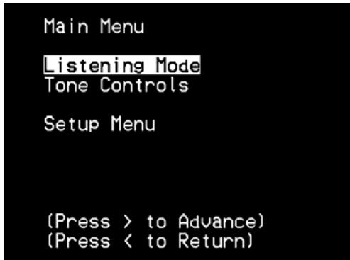
To navigate through these Main Menu options and their sub-menu selections, please refer to above section about "DISPLAY THE OSD" and "NAVIGATING THE OSD AND MAKING CHANGES".
LISTENING MODE
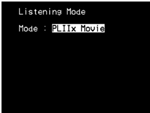
The T 737 offers eleven distinct listening modes, tailored for different types of recording or program material. With a two-channel (Stereo) source, the following listening modes can be selected:
ANALOG BYPASS
All analog signals remain in the analog domain without analog-to-digital conversions. At Analog Bypass, the DSP circuitry is bypassed but full tone control functions remain. "Bass management" or "Speaker Settings" are also not in effect as these are DSP functions.
STEREO
All output is directed to the front left/right channels. Low frequencies are directed to the subwoofer if one is present in the Speaker settings. Select "Stereo" when you wish to listen to a stereo (or monaural) production, such as music CD or FM broadcast, without surround enhancement. Stereo recordings whether in PCM/digital or analog form and whether surround-encoded or not encoded, are reproduced as recorded.
Dolby Virtual Speaker technology creates a highly compelling 5.1-channel listening experience from as few as two speakers, making it an ideal entertainment solution for locations where space for multiple-speaker setups is limited.
Dolby Virtual Speaker models the sound of a playback system into two different listening environments, based on acoustic measurements of real rooms:
DVS Ref is a small, well-damped room appropriate for both movies and music-only recordings.
DVS Wide is a larger room, more like a concert hall or movie theatre.
PRO LOGIC IIx
Dolby Pro Logic IIx processes both stereo and 5.1 signals into a 6.1 or 7.1 channel output. At Dolby Pro Logic IIx, you can choose PLIIx Movie or PLIIx Music modes to tailor your listening experience to the source material. Dolby Pro Logic IIx surround processing yields more stable imaging and full bandwidth sound to the rear channels in Movie mode offering sound that is more similar to Dolby Digital decoding. For two channel signals, PLIIx Music mode also features three additional user controls - Dimension, Center Width, and Panorama. See also section about "ADJUSTING LISTENING MODES" below. The following chart shows the channels available assuming they are enabled in the "SPEAKER CONFIGURATION" menu.
| Listening Mode Two-Channel Sources | Active Decoded Output Channels | |
| 6.1 Speaker System | 7.1 Speaker System | |
| PLIIx Music PLIIx Movie | Front (left & right), Center, Surround (left & right), Back Surround, Subwoofer | Front (left & right), Center, Surround (left & right) and Back Surround (left and right) and subwoofer |
USING THE T 737 - MAIN MENU
NEO:6
Two-channel recordings, whether stereo or surround-encoded, are reproduced with Neo:6 surround with output to front left/right, center and discrete left/right surround channels plus subwoofer (assuming these are present in the current "Speaker Configuration"). The T 737 provides two DTS NEO:6 variations - NEO:6 Cinema and NEO:6 Music. See also section about "ADJUSTING LISTENING MODES" below.
EARS
Two-channel recordings, whether stereo or surround-encoded, are reproduced with proprietary NAD surround processing with output signals to the front left/right, center and discrete left/right surround channels, plus subwoofer (assuming these are present in the current "Speaker Configuration"). EARS does not employ the surround back speakers (if any).
EARS extracts the natural ambience present in nearly all well-produced stereo recordings. It does not synthesize any ambience or other sonic elements and thus remain truer to the sound of the original musical performance than most other music-surround options.
Select EARS for listening to stereo music recordings and broadcasts. EARS produces a subtle but highly natural and believable ambience from nearly all "natural-acoustic" stereo recordings. Typically, these include classical, jazz, and folk genres as well as numerous examples from others. Its virtues include realistic, stable "front-stage" sonic imaging and spacious but unexaggerated ambient "virtual acoustics" that remain faithful to the original recording.
ENHANCED STEREO
All recordings are reproduced in stereo via the maximum speaker complement configured in the current "Speaker Configuration". Enhanced stereo can be useful for maximum volume from all channels or for multispeaker background music (cocktail party) listening. For this mode, Front, Center, Surround and Back speakers can be turned ON/OFF as desired.
7CH (CHANNEL) STEREO
Two-channel recordings are reproduced with output signals to the front left/right, center, discrete left/right surround channels, back surround left/right plus subwoofer (assuming these are present in the current "Speaker Configuration"). The Back Surround (left/right) output level is -3 dB lower than the other channels.
ADJUSTING LISTENING MODES
Several of the T 737's listening modes have one or more selectable variations and adjustable parameters that you can modify to suit your personal preferences. At Listening Mode menu, use a combination of the [ / ] and [ / ] keys to navigate and effect desired settings.
NOTE
Listening Mode parameter changes are maintained when you change listening modes. You may also save a modified Listening Mode for easy recall by saving it to a Preset (See "AV PRESETS SETUP" below under Setup Menu discussions).
PRO LOGIC IIx
PLIIx MOVIE is optimized for film soundtracks.
PLIIx MUSIC for music recordings.
Center Width (0 to 7): Modifies the "hard-centeredness" of the center image, by gradually mixing mono center content to the Front left/right speakers as well. A setting of 0 retains the center-channel-only default while a setting of 7 yields a fully phantom center channel.
Dimension (-3 to +3): Adjusts front-rear emphasis of the surround effect independently from the relative channel levels.
Panorama (On/Off): Adds a "wrap around" effect by extending some stereo content into the surround channels.
NOTE
Pro Logic IIx mode will decode as Pro Logic II mode when the "Back" surround speakers are set to "Off" from "Speaker Configurations" menu. Refer also to the item about "SPEAKER CONFIGURATION" under the "SPEAKER SETUP" segment of "OPERATION - USING THE T 737 - SETUP MENU" section.
NEO:6
Neo:6 Cinema is optimized for film soundtracks.
Neo:6 Music for music recordings.
CENTER GAIN (0 to 0.5): Adjust for better center image in relation to the surround sound channels.
TONE CONTROLS
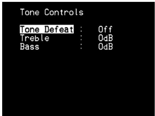
"Tone Defeat" gives one the choice of varying or completely bypassing the tone control section of the T 737. If "Off" is selected, the Tone Control circuits are active. Select "On" to bypass the Tone Controls effectively defeating the effect of the tone control circuits.
The T 737 has two Tone Control levels - Treble and Bass. Bass and Treble controls only affect the low bass and high treble leaving the critical midrange frequencies free of coloration.
These controls allow one to tweak on-the-fly, the frequency response of the source. Use the [ / ] keys to adjust Treble and Bass within the range ± 10 dB.
USING THE T 737 - SETUP MENU
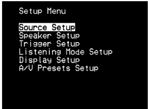
SETUP MENU
The Setup Menu allows one to customize the operation of the T 737 to the ancillary equipment used in one's specific AV system. Unless your system exactly matches the factory defaults, you will need to use the Setup Menu to configure the settings of your T 737.
At Setup Menu, the following are configurable – Source Setup, Speaker Setup, Trigger Setup, Listening Mode Setup, Display Setup and A/V Presets Setup.
To navigate through these Setup Menu options and their sub-menu selections, please refer to above section about "DISPLAY THE OSD" and "NAVIGATING THE OSD AND MAKING CHANGES".
SOURCE SETUP
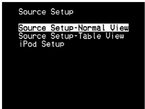
From Source Setup menu, pressing [▶] will direct you to the Source Setup menu wherein you could adjust, allocate or change the settings of the following - Source Setup (Normal View), Source Setup (Table View) and iPod Setup.
SOURCE SETUP (NORMAL VIEW)
The Source Setup (Normal View) makes it possible to set, allocate or change the following settings.
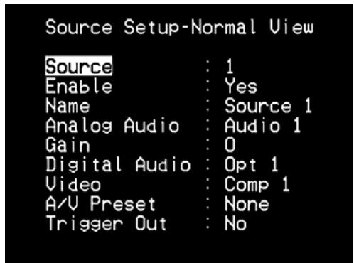
SOURCE
The T 737 is equipped with 9 configurable sources (Source 1-8 and Source T). The settings for each Source are dependent on the configurations set forth in the parameters for that particular Source window.
While at "Source" line item, use [/] keys to toggle through the Sources.
NOTE
Source 4 is defaulted to iPod. For Source 4 to be changed and assigned to other inputs, go to "iPod Setup" menu under the "Source Setup" menu. At iPod Setup menu, set "Enabled" to "No" - you can now assign Source 4 to other inputs or settings as desired.
ENABLE
One can enable/disable a Source via this option. This is particularly useful if only few Sources are used and one directly selects the Source from the front panel, bypassing unused sources.
To enable or disable a particular Source, scroll to "Enable", press [▶] and then [▲/▼] to select "Yes" or "No".
NAME
A new Name maybe assigned to a Source label. For example, if your DVD player is attached to "Source 1", it is possible to rename "Source 1" to "DVD".
In order to rename the Source label, scroll to "Name", press [▶] and then [▲/▼] to pick and select through the alphanumeric selections.
Press [▶] to move to the next character and at the same time save the changes done on the current character. The name can be as long as eight characters.
The new Name will be shown in the VFD as well as on the OSD.
ANALOG AUDIO
The T 737 has eight analog audio inputs including 7.1 input. These analog inputs - Audio 1, Audio 2, Audio 3, Audio 4, Audio 5, Audio 6, Audio Front and 7.1 Input can be variably assigned to each Source.
Scroll to "Analog Audio" and then press [▶] to select and assign an analog audio input to the particular Source. If "Off" is selected, no incoming analog audio signal is selected by the particular Source.
NOTE
An incoming digital signal present at the assigned digital input will always take precedence over the assigned analog audio input, even if both are present. To maintain the analog audio input for the particular Source, select "Off" at the "Digital Audio" setting of the same "Source" menu.
GAIN
Gain adjustment allows all sources to playback at the same volume level. In this way, so you don't need to adjust the volume level every time a new source is selected. It is generally preferable to reduce the level of the loudest source rather than making louder the softer sources.
Scroll to "Gain", press [▶] and then [▲/▼] to step through the desired level from -12 to +12.
DIGITAL AUDIO
To take advantage of the T 737's high performance surround and digital audio circuitry, it is advisable that its Digital Audio inputs are selected.
There are four Digital Audio inputs selectable for the T 737 - Optical 1, Optical 2, Optical Front and Coaxial IN.
Another option is "Off" whereby no incoming digital audio signal is selected by the particular Source.
NOTE
An incoming digital signal present at the assigned digital input will always take precedence over the assigned analog audio input, even if both are present. To maintain the analog audio input for the particular Source, select "Off" at the "Digital Audio" setting of the same "Source" menu.
VIDEO
A specific video input can be assigned a particular Source. The following are the assignable Video inputs:
HDMI 1,HDMI 2
- Component 1, Component 2, Component 3
- S-Video 1, S-Video 2, S-Video 3, S-Video 4, S-Video Front
Video 1, Video 2, Video 3, Video 4, Video Front
Another option is "Off" wherein the particular Source is prompted not to select any Video input.
ABOUTVIDEOFORMATS
For many years, there was only one type of video format used. Composite video signals include the Luminance (black & White) and Chroma (color) signals combined on one wire. S-Video uses separate wires in a single cable for Luminance and Chroma signals. Component Video goes a step further with separate cables for Luminance and the two elements of Chroma. For NTSC (America, Japan) as well as PAL signals (Europe, Asia) these are labeled Y, Cr, Cb. Television studios use the Component Video format to keep these signals separate in order to maintain the best quality. As consumer video equipment has improved this higher quality format has been included.
VIDEO FORMAT CONVERSION
The T 737 is equipped with a Video Format Converter. This allows for a simplified video connection between the T 737 and your TV Monitor when using multiple video formats such as Composite (CVBS), S-Video, and Component (YUV). This format change is accomplished by encoding the analog video signal into a digital signal using a very high quality digital encoder to maintain the best possible picture quality. Once in a digital format, it can be decoded into any of the three standard analog video formats.
It is suggested that you select the highest quality video format available on your TV Monitor and utilize this for your Monitor OUT connection from the T 737 to the TV Monitor. In most cases this will be Component Video, but on some older TV's S-Video may be the best quality connection. See also the item "COMPONENTVIDEO 1-3, COMPONENTVIDEO OUT" under "Identification of Controls - Rear Panel" discussions.
NOTES
Video signals are converted between all three formats:
Video (Composite), S-video and Component Video.
- All three monitor outputs will always be active no matter what the source format is.
- OSD menu is always available on all three output formats - Video (Composite), S-Video and Component Video.
SWITCHING OF VIDEO SYSTEM (FOR 230V VERSION MODEL ONLY)
The T 737 video format system can be switched between PAL and NTSC system. This allows your T 737 to adapt to the applicable video system of the source component and output media.
For example, if the source component (maybe a DVD player) connected to the T 737 is set to a 576i/576p/720p resolution or PAL only, the following conditions must be followed
- the output media (a television) connected to the T 737 must have the same resolution capabilities (i.e., 576i, 576p, 720p, PAL)
the T 737 must be set to "PAL" system.
If the video system setting and applicable resolution settings of the source component, output media and the T 737 are not compatible with each other, the T 737 will have no video output. The same applies in the case of NTSC system components (480i, 480p, 720p, 1080i, NTSC).
The following is the procedure on how to switch the T 737 video system
1 Set AVR 3's DEVICE SELECTOR to "AMP".
2 At any Source setting, direct the AVR 3 remote control to T 737's remote sensor.
3 Press and hold AVR 3's [PAL/NTSC] button until the upper line of the VFD shows "USER DEFAULT" and the lower line "PAL" (or "NTSC").
4 Release AVR 3's [PAL/NTSC] button when the video system you prefer is shown.
IMPORTANT NOTES
Video system switching is only applicable at Component Video, S-Video and Video monitor output.
- 480p/576p, 720p and 1080i component video input signals cannot be converted into S-Video or Video format.
1080p component video input signals can only be outputted at component video monitor out.
HDMI signals cannot be converted to analog signals.
A/V PRESET
A particular Source can be assigned a stored Preset. The parameters set up in the selected Preset number will be adopted into the particular Source it is assigned (Please refer to the separate item below about "AV PRESETS SETUP" for a better understanding of A/V Preset settings).
Scrolling to "A/V Preset" and by pressing [▶] and then [▲/▼] keys, a Source could be assigned a Preset number ranging from Preset 1 to 5.
If it is desired not to assign the particular Source a Preset setting, select "None".
TRIGGER OUT
The Trigger Out for a particular Source is dependent on the configurations done in a separate menu on Trigger Setup (See "TRIGGER SETUP" below). If Trigger output is assigned to "Src Setup" in the separate "Trigger Setup" menu window, +12V will be available at +12V TRIGGER OUT port whenever a Source with "Trigger Out" set to "Yes" is recalled.
Another option is "No" whereby the particular Source is not assigned any Trigger Out.
USING THE T 737 - SETUP MENU
SOURCE SETUP (TABLE VIEW)
The Source Setup (Table View) reflects the settings made in the Source Setup (Normal View) menu. All the Source settings are summarized and displayed in tabulated form in the Source Setup (Table View).
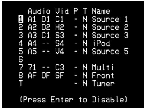
Navigating through the Source Setup (Table View) via a combination of [ ] and then [ / ] keys, one will have the benefit of directly changing the settings for "Audio, Video, Preset, Trigger and Name" without going back to the Source Setup (Normal View) menu. Toggle [ENTER] to enable or disable a Source.
iPod SETUP
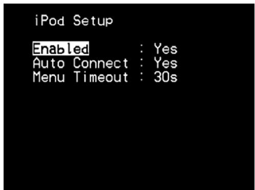
The iPod Setup menu allows you to preset the following associated settings when iPod is the selected source:
Enabled: Select "Yes" to default Source 4 to iPod mode or "No" for Source 4 to be an assignable source input.
Auto Connect: Select "Yes" to automatically enable and connect the iPod player docked in the linked NAD iPod docking station when Source 4 (the default iPod source allocation in the T 737) is selected. Select "No" if you do not want for the iPod connection automatically connected.
Menu Timeout: Set the time for the OSD to revert to the "Now Playing" display when the iPod menu has been left idle (no scrolling or navigation being done) for the specified time out time. For the "Now Playing" OSD to be shown, there should be a song paused or being played before going to the iPod menu. You can set the "Menu Timeout" between the range 5s to 60s at 5s increments. If you do not want for the menu to timeout, select "Off".
SPEAKER SETUP
After connecting all ancillary sources and other combinations, the Speaker Setup menu will guide you on how to manage and setup your speakers in order to achieve optimum sound acoustics in your listening environment.

The following are the Speaker Setup Menu sections.
Every surround-sound system requires "bass-management" to direct low-frequency content from any or all channels to the speakers best able to reproduce it. For this function to operate correctly, it is important that you correctly identify your speakers' capabilities. We use the terms "Small", "Large" and "Off", but note that physical size may be irrelevant.
- A "Small" speaker is any model, regardless of physical size, that lacks significant deep-bass response, that is, below about 150Hz .
- A "Large" speaker is any full-range model, that is, one with deep-bass response
- An "Off" speaker is one that is not present in your system. For example, you might not have any surround-back speakers installed; in that case, you would set the "Back" setup item to "Off".
The Speaker Configuration is "global"; that is, it remains in force with all inputs and in all listening modes. However, speaker settings are part of the T 737's Preset system. Consequently, multiple speaker settings can be stored for easy recall as different types of recordings or listening modes require.
Speaker Configuration can be managed and adjusted by pressing a combination of [ ] and then [ / ] keys. Set "Front", "Center", "Surround" and "Back" to "Large", "Small" (Small 60 Hz up to Small 150 Hz) or "Off" as your subsystem's speakers require.
Set "Subwoofer" to "On" or "Off", selecting "On" only if you have a subwoofer connected to the SUBW PRE OUT jack. If the "Subwoofer" is set to "Off", "Front" speaker will automatically be set to "Large".
SPEAKER LEVELS
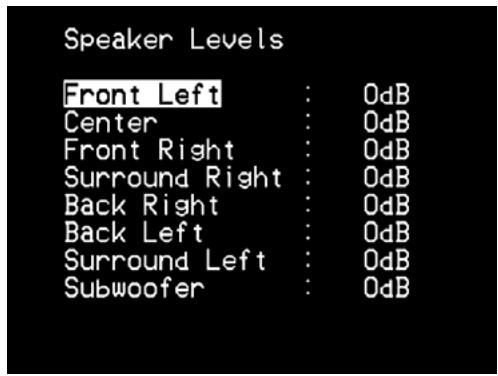
Adjusting the relative balance of your system's loudspeakers ensures that surround-sound recordings, whether music or film, will present the balance of effects, music, and dialog that the artists intended. Additionally, if your system incorporates a subwoofer it establishes a correct relationship between the volume of the subwoofer and the other speakers, and thus of low-frequencies (bass) to other sonic elements.
USING AN SPL METER
It is quite practical to perform the T 737 level setup routines "by ear", and careful work will produce acceptably accurate results. However, the use of an inexpensive sound-pressure level (SPL) meter, such as Radio Shack part number 33-2050, makes this task easier, more accurate and more repeatable. Ownership of such a meter could prove a valuable audio tool.
The SPL meter should be placed at the primary listening position, at approximately the height of the seated listener's head. A tripod is helpful but with a little duct tape almost anything — a pole lamp, music-stand, or ladder-backed chair, for example — can do as well. Just be sure that no large acoustically reflective surfaces obstruct or are near the microphone element.
Orient the meter with its microphone (usually at one end) pointing straight up toward the ceiling (not toward the speakers) and ensure that "C" weighting scale is selected. Set the meter to display 75 dB SPL. On Radio Shack meters, this necessitates either setting the meter to its 80 dB range and taking your readings at the -5 point or selecting the 70 dB range and reading at the +5 point.
SETTING SPEAKER LEVELS AT TEST MODE
While at "Speaker Levels" menu, press the AVR 3 remote's "Test" key activating the T 737's Speaker Levels balancing test signal. You will hear a "surf" sound as you step through your speakers beginning with the Front Left. To test each channel, use AVR 3's [ / ] keys to move up or down the speaker channels. If you do not hear the test signal, check your speaker connections or your "Speaker settings" menu settings.
Use the remote's [ / ] keys to adjust the loudness of the noise output from the currently playing channel to the required level (it's usually simplest to begin with the Front Left). As you cycle the test signal around the speakers, the OSD will highlight the currently playing channel. The "level offset" reading on the right will change by 1 dB increments; ± 12 dB adjustment is available. After adjusting a channel, press [ / ] to effect the change in level. Press [ / ] to go to the next channel.
NOTE
If you are balancing levels "by ear", choose one speaker—usually the center—as a reference and adjust each of the others in turn to "sound as loud" as the reference. Be sure that you remain in the primary listening position while balancing all channels.
To produce the same SPL meter reading (or subjective loudness), use a combination of [ / ] and then [ / ] to adjust each speaker.
NOTES
- All speakers must be in their final locations before level-setting.
- Your subwoofer (if any) should be set with its integral crossover defeated, or if undefeatable, set to its highest-possible frequency if you are using the T 737's Subwoofer output. Final subwoofer-level adjustment "by-ear", using music and film sound material, is frequently useful.
- Due to the effects of room acoustics, matched-pair speakers (front; surround; back) will not always calibrate to exactly the same level offset readings.
You can exit "Test" mode at any time by pressing the [ ] key, bringing you back to "Speaker Setup" menu.
USING THE T 737-SETUP MENU
SPEAKER DISTANCE
| Speaker Distance | |
| Unit of Measure : Meters | |
| Front Left : 0.0 | |
| Center : 0.0 | |
| Front Right : 0.0 | |
| Surround Right : 0.0 | |
| Back Right : 0.0 | |
| Back Left : 0.0 | |
| Surround Left : 0.0 | |
| Subwoofer : 0.0 |
Your system's speaker distance settings are a subtle but important refinement of your setup. Informing the T 737 of the loudspeaker-to-listener dimensions of each speaker automatically imposes the correct delays, optimizing imaging, intelligibility and surround-sound ambience. Enter your dimensions with precision within about 1 foot (30 cm).
SETTING SPEAKER DISTANCE
While at "Speaker Distance" menu, use the [ / ] keys to individually set Front Left, Center, Front Right, Surround Right, Back Right, Back Left, Surround Left and Subwoofer to the distance measuring from your principal listening position to the front surface of their corresponding loudspeakers. Distance can be set up to 30 feet or 9 meters.
Distance can be displayed as feet or meters selectable at the "Unit of Measure" item.
ADJUSTING THE VOLUME
In addition to the Volume knob, use the AVR 3's [VOL / ] to adjust the "master volume" of the T 737 raising or lowering the channels altogether. A momentary keypress will change the master volume by 1 dB increments. If you hold down [VOL / ] the master-volume change will "run-on" until the key is released.
Since recordings vary considerably in overall average level, there is no imperative to listen at any particular master-volume setting. A setting of -20 dB may sound "as loud" from one CD or DVD as -10 dB does from another.
The T 737 will power-up from Standby mode at whatever master volume setting was last used; however, if the prior setting was greater than -10 dB, the T 737 will power up at -10 dB. This prevents inadvertently beginning a session at excessive volume.
MUTING THE SOUND
Use the AVR 3's "Mute" key to silence all channels completely. Muting is always available regardless of the source or listening mode selections.
NOTES
- Changing input or listening-mode selections does not release muting.
- Adjusting the volume level via the AVR 3 or the front-panel volume knob will automatically release the mute function.
TRIGGER SETUP
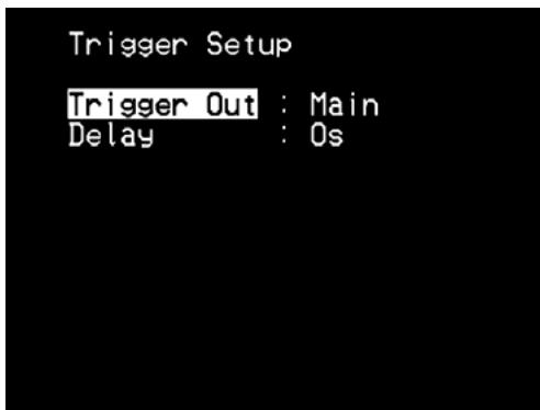
The T 737 features a configurable +12V DC Trigger Output that can be used to activate a component or system it is fed into.
TRIGGER OUT
Triggers are low voltage signals used to turn on/off other compliant devices. There are two choices where +12V DC output can be assigned and these are - Main and Src Setup.
Main: +12V DC is available at the assigned Trigger Out when the T 737 is at powered state.
Src (Source) Setup: If Trigger Output is linked to "Src Setup", +12V DC is available at Trigger Out whenever the particularly assigned Source is selected.
DELAY
The availability of +12V DC at Trigger OUT can be regulated. If it is desired that +12V DC is available without delay the moment Trigger OUT is linked to its assigned setting, set Delay to 0s. Otherwise, one can select through a delay time of 1s to 15s.
LISTENING MODE SETUP
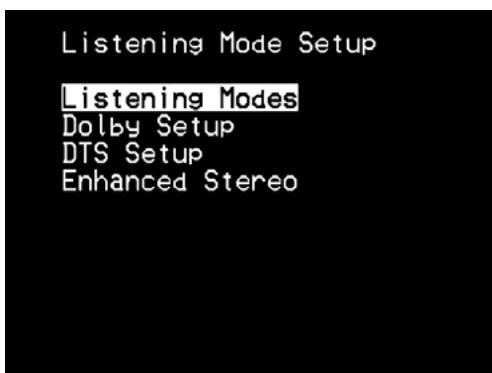
The T 737 has various listening mode options and is mostly configurable. These are provided to reproduce a variety of sound effects depending upon the content of the source to be played. Use a combination of [ ] and [ / ] keys to configure the following settings.
LISTENING MODES
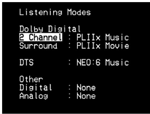
The audio format as detected by the selected Source can be automatically configured and processed through the following options:
Dolby Digital
Dolby Digital is the multi-channel digital signal format developed in the Dolby laboratories. Discs bearing the double-D symbol were recorded with up to 5.1 channels of digital signals, reproducing a much better sound quality, with dynamic and spatial sound sensations that are much better than in the previous Dolby Surround.
A Dolby Digital audio input can be configured relative to its format.
2 Channel: If the detected audio is a 2 Channel Dolby Digital signal, you can default it to one of the following settings – PLIIx Movie, PLIIx Music, DVS Wide, DVS Ref or None.
Surround: If the detected audio is a Surround Dolby Digital signal, you can default it to one of the following settings - Dolby D Ex, PLIIx Movie, PLIIx Music, DVS Wide, DVS Ref, Stereo or None.
None: If "None" is selected, the Dolby Digital format will follow the "Digital" setting set forth at "Other" option under this menu section. See discussion below about "OTHER".
Dolby Digital EX
Using a Matrix decoder, this method creates the back channel (sometimes also called the "surround center") by means of signals on the left and right surround channels recorded in Dolby Digital 5.1, reproduction being provided in Surround 6.1. This method should be selected with sources bearing the (double-D symbol)-EX, recorded in Dolby Digital Surround EX.
With this additional channel you will experience improved dynamics and a better sensation of movement within the sound field. If media sources recorded in Dolby Digital EX are decoded with a Digital EX decoder, the format is detected automatically, and the Dolby Digital EX mode is selected. However, some media sources recorded in Dolby Digital EX can be detected as simple Dolby Digital media sources. In this case Dolby Digital EX should be selected manually.
NOTE
Please refer to the section "LISTENING MODE" at the Main Menu discussions for a description of PLIIx Movie, PLIIx Music and Stereo modes.
DTS
The Digital Theater System Digital Surround (simply called DTS) is a multi-channel digital signal format that can process higher data rates than with Dolby Digital. Although both Dolby Digital and DTS are 5.1 channel media formats, discs bearing the "DTS" symbol are thought to provide better sound quality due to the lower audio compression required. It also offers a broader dynamic, producing magnificent sound quality.
A DTS input can be defaulted to one of the following options: - Neo:6
Cinema, Neo:6 Music, DTS Stereo or None.
If "None" is selected, the DTS signal will follow the "Digital" setting set forth at "Other" option under this menu section. See discussion below about "Other".
OTHER
If "None" is selected above for any of the Dolby Digital 2 Channel, Dolby Digital Surround and DTS options or if the audio input is an analog signal, this "Other" section will manage the default audio format as per the "Digital" or "Analog" settings.
Digital: The detected digital input can be configured by way of one of the following options - 7ch Stereo, En Stereo (Enhanced Stereo), EARS, Neo:6 Music, Neo:6 Cinema, PLIIx Music, PLIIx Movie, DVS Wide, DVS Ref or None.
Analog: If the audio input is an analog signal, the following are the surround modes the input can be defaulted – 7ch Stereo, En Stereo (Enhanced Stereo), EARS, Neo:6 Music, Neo:6 Cinema, PLIIx Music, PLIIx Movie, DVS Wide, DVS Ref, Stereo or None.
NOTE
All these Listening Modes for "Dolby Digital", "DTS" and "Other" can be directly changed by pressing the "LISTENING MODE" button on the front panel, AVR 3's [SURR] button or through the "Listening Mode" option at the Main Menu window.
USING THE T 737-SETUP MENU
DOLBY SETUP
Under this menu, the Dolby Digital's Dynamic Range Control can be adjusted as well as the settings for Dolby Digital Pro Logic IIx Music.
Dyn Range Ctrl (Dynamic Range Control): You can select the effective dynamic range (subjective range from soft to loud) for playback of Dolby Digital soundtracks. For fully cinematic effect, always select 100, the default. Settings of 75, 50, and 25 progressively reduce dynamic range, making soft sounds comparatively louder while limiting the peak loudness of loud ones.
The 25 setting will yield the least dynamic range and is best for late-night sessions or other times when you wish to retain maximum dialog intelligibility while minimizing overall volume levels.
Dolby Pro Logic IIx Music: Please refer to the item about "PRO LOGIC PLIIx" under the topic "ADJUSTING LISTENING MODES" at the "USING THE T 737 - MAIN MENU" discussions above.
DTS SETUP
Under this menu, the Center Gain settings of DTS Neo:6 Music can be adjusted. See discussion below about "DTS NEO:6 MUSIC".
DTS SURROUND MODES
The following are further descriptions about the DTS surround modes.
DTS-ES™ DISCRETE 6.1
Since the signals of the 6.1 Surround channels (including the back channel) are completely independent, it is possible to achieve the sensation that the acoustic image is moving about freely among the background sounds, 360 degrees surrounding the listener.
Although maximum quality is achieved with sound tracks recorded using this system and reproduced using the DTS-ES decoder, when played with a conventional DTS decoder, the back surround channel is automatically downmixed in the surround right and surround left channels of the surround system, in such a way that none of the signal components are lost.
DTS-ESTM MATRIX 6.1
In this format, the additional signals of the back channel receive a matrix encoding and are inputted into the right and left surround channels. During reproduction they are decoded to the right, left and back surround channels.
Since this bit-stream format is 100% compatible with conventional DTS signals, the DTS-ES Matrix 6.1 format effect can also be achieved from sources with DTS-ES 5.1 signals.
Naturally, it is also possible to reproduce from a DTS 5.1 channel decoder, signals recorded in DTS-ES 6.1.
When a DTS-ES decoder processes a discrete DTS-ES 6.1 or in Matrix 6.1, these formats are automatically detected and the Optimum Surround mode is selected. However, some DTS-ES Matrix 6.1 sources may be detected as DTS. In this case the DTS-ES Matrix mode should be selected manually in order to reproduce them.
DTS NEO:6™ SURROUND
This mode applies the conventional 2-channel signals such as digital PCM or analog stereo signals to the high precision digital matrix decoder used for DTS-ES Matrix 6.1 to achieve 6.1-channel surround playback. DTS Neo:6 surround includes two modes for selecting the optimum decoding of the signal sources:
DTS NEO:6 CINEMA : This method is ideal for the reproduction of movies. The decoding takes place by emphasizing the separation in order to achieve the same atmosphere with 2-channel, as with 6.1-channel sources.
DTS NEO:6 MUSIC : Mainly recommended for music reproduction. The right and left front channels do not pass through the decoder and are reproduced directly so there is no loss in sound quality, and the effects of the right surround, left surround, central and back surround channels add a natural sensation of expansion of the sound field.
Center Gain (0 to 0.5): Adjust for better center image in relation to the surround sound channels.
ENHANCED STEREO
Please refer to the same item about "ENHANCED STEREO" under the topic "LISTENING MODE" at the "USING THE T 737 - MAIN MENU" discussions above.
DISPLAY SETUP
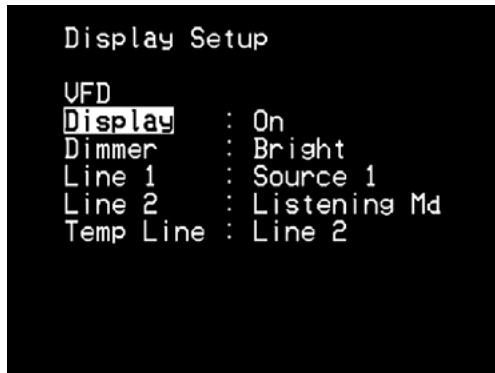
The Vacuum Fluorescent Display (VFD) and On-Screen Display (OSD) can be shown in various ways by navigating through the parameters at the "Display Setup" menu. Use a combination of [ ] and [ / ] keys to step through the "Display Setup" menu items.
Display: Select "On" to display all applicable data or characters at the VFD. Nothing will be shown at VFD if "Off" is selected. However at "Temp" setting, whenever any of the front panel controls or their corresponding keys in the remote control is activated, the appropriate VFD characters will be shown temporarily and then fade away.
Dimmer: If it is desired to reduce the brightness of the VFD, set Dimmer to "Dim". Otherwise, select "Bright" to return to normal VFD brightness.
Line 1, Line 2: The VFD shows two main lines of data or characters. Line 2 is the line of data or characters located at the lower bottom of the VFD while directly above it is Line 1. For both lines, one can select which display could be shown by choosing through the following
Source: Shows the active Source.
Volume: Current Volume level is shown.
Listening Md (Listening Mode): Selected Listening Mode is shown.
AudioSrcForm (Audio Source Format): Shows the audio format detected at the active Source.
Off: Select "Off" if it is desired not to show any data at the applicable Line.
Temp Line: Choose between Line 1 and Line 2 as the desired line where VFD will be temporarily shown if "Off" is selected at "Display" option as described above.
NOTE
The configurations set forth at "Display Setup" are carried over whenever it is enabled during A/V PRESETS SETUP setting. Refer also to the next section about "A/V PRESETS SETUP".
A/V PRESETS SETUP
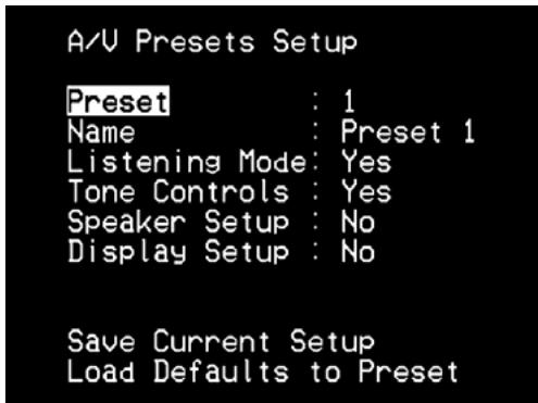
The T 737's simple but powerfully flexible system of "Presents" allows you to customize virtually every aspect of your audio-video playback. The "Listening Mode", "Tone Controls", "Speaker Setup" and "Display Setup" parameter settings are stored together as a Single Preset.
You might create one Preset optimized for pop music and another for classical. One more Preset can be set up to recall each family member's favorite setting or one for fully cinematic home-theater playback and yet another one for late-night movies, with each Preset fine-tuned to a particular scenario or preference.
CREATING PRESETS
Creating a Preset consists simply of storing a complete set of the parameters set forth in the "Listening Mode", "Tone Controls", "Speaker Setup" and "Display Setup" configurable through "Setup Menu".
Go to "A/V Presets Setup" to save a collection of said parameter settings to a Preset. Select a Preset number and by a combination of pressing the [ / ] keys, you can selectively include in the particular Preset any of the above-mentioned parameter settings by choosing "Yes." If you decide not to include in the particular Preset a certain parameter setting, select "No".
Now in order to save the settings chosen for the particular Preset number, scroll down to "Save Current Setup" and press the [▶] key. If you chose to load instead the default settings, scroll down to "Load Defaults to Preset" and press the [▶] key to restore the default settings.
In addition to the parameter settings, the Preset label itself can be assigned a new name. This new Name will be shown in the VFD as well as on the OSD.
To rename the Preset label, scroll to "Name" and press [▶] to go the character. Then, press [▲/▼] to pick and select through the alphanumeric selections. Press [▲/▶] to move to the next character or back to the previous character and at the same time save the changes done on the current character.
RECALLING PRESETS
You may recall a Preset at any time using the AVR 3 remote control. Press the AVR 3's A/V PSET key and then the numeric key 1-5 corresponding to the desired preset number. The newly recalled Preset will then manifest or replace the previous Preset (if any).
LISTENING TO AM/FM RADIO
The T 737's internal AM/FM tuner offers very high quality sound from radio broadcasts. The reception and sound quality will always be dependent to a degree however on the type of antenna(s) used as well as proximity to the broadcast origin, geography and weather conditions.
ABOUT ANTENNAS
Connect the supplied lead-type FM antenna to the FM antenna input. Extend the lead. Experiment freely with your antenna placement and orientation until you get the clearest sound and lowest background noise. Fix the antenna in the desired position by using thumb tacks, push pins or any suitable means. In areas of poor FM reception, an exterior FM antenna can improve performance dramatically. If radio listening is important to you, consider consulting an antenna installation professional to optimize your system.
The AM loop antenna supplied with the T 737 (or a suitable replacement) is required for AM reception. Open the clip terminal lever; insert the wire making sure to match the color-coded (white and black) ends of the wire to that of the terminal and close the lever ensuring that the lever locks the wire in place. Testing different positions for the antenna may improve reception; vertical orientation will usually produce the best results. Antenna proximity to large metal objects (appliances, radiators) may impair reception, as will attempts to lengthen the wire to the loop.
The supplied AM "loop" antenna will usually provide adequate reception. However, an exterior AM antenna can be used to improve reception. Consult an antenna professional for more information.
IMPORTANT NOTICE
Unless otherwise specifically stated, navigating or accessing AM/FM functions can be undertaken by using either the AVR 3 remote control or the front panel buttons. If the control button or icon button being referred to is available on the AVR 3 remote control and front panel, then the reference to said button is applicable to both the AVR 3 remote control and front panel.
NOTE
When using the AVR 3 remote control to carry out AM/FM commands, ensure that the DEVICE SELECTOR is set to "TUN".
ASSEMBLING THE LOOP ANTENNA
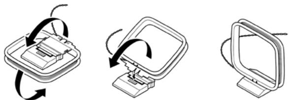
1 Rotate the outer frame of the antenna.
2 Insert the bottom edge of the outer frame into the groove on the stand.
3 Extend the antenna cord.
SELECTING A TUNER BAND
Press the [AM/FM/DB] button on the AVR 3 while at AMP or TUNER device selector page. Each subsequent press of either button will toggle you through AM, FM and XM (or DAB) band. Stop (release button) at your desired tuner band.
TUNING AM/FM STATIONS
Upon selecting AM or FM band, use [TUNE / ] on the AVR 3 - toggle in to perform slow manual search, press and hold to automatically search.
The front panel or AVR 3's [▶] buttons can also be used to tune for stations.
1 Press [ / ] on the front panel momentarily to step up or down between AM or FM frequencies.
2 Press and hold [▲/▲] for more than 2 seconds to search up or down - the T 737's tuner will stop at the next sufficiently strong signal it encounters.
3 Pressing the [ / ] during the search process will stop the search.
DIRECT TUNING
If you know your desired station's frequency allocation, you can tune directly to the station.
1 Toggle [ENTER] button to switch between "Preset" and "Tune" mode (see the lower line of the VFD). Select "Tune" mode.
2 Using the numeric keys of the remote control, key-in the frequency allocation of the station. For example, to enter 104.50MHz, press "1","0", "4","5" and "0" or press "1","0","4" and "5".
SETTING RADIO PRESETS (AM/FM)
The T 737 can store up to 30 FM and 30 AM stations for immediate recall.
1 To store a radio preset, first tune the desired frequency (see above), then press AVR 3's [MEMORY] key.
2 The VFD will show the next available Preset number (If there are no more vacant Preset number, you can overwrite an existing Preset number by pressing the [ / ] buttons to select the Preset number you want to overwrite). Press the [MEMORY] button again to store the desired frequency on the Preset number shown or use the [ / ] buttons to select another available Preset number.
3 Then, press [MEMORY] button again. Your desired frequency is now stored in the assigned preset.
4 Press [ / ] to step up or down between presets. Press and hold [ / ] to "scroll" continuously up or down. The AVR 3 remote's [PRESET 山 / 山 山 ] keys work similarly.
AUTOMATIC PRESET
Preset stations may also be programmed automatically for the entire FM (or AM) band.
1 Toggle the [AM/FM/DB] button to select FM (or AM) band.
2 Press and hold the [MEMORY] button until the station frequency indication begins to increase.
3 Release the button and note that the tuner will search the entire FM (or AM) band, and stop briefly at each station that has acceptable signal strength. The T 737 will automatically assign a preset number to each station, and then search for the next station. Up to 30 of the best received FM stations (or 30 AM stations) will be automatically stored.
DELETEING A STORED PRESET
You can empty a preset by deleting the stored information.
1 Select the preset number to be deleted.
2 While at the selected preset number, press the [DELETE] button.
3 The preset will then be deleted and "DELETED" scrolls on the display.
4 To clear all the Presets at the same time, repeat step 2 again but this time do not release the [DELETE] button. Press and hold [DELETE] button until the current Preset number shown in the VFD is extinguished (P--). All Presets are now deleted.
CHOOSING THE TUNER MODE
The AVR 3's [TUNER MODE] key is a dual-purpose control. Toggle [TUNER MODE] toggle to switch between FM Stereo mode or FM Mono. In the normal position, "FM STEREO ON", only the stations with a strong signal can be listened to, and the noise between stations is muted.
Pressing the [TUNER MODE] button again ("FM STEREO OFF") allows distant and potentially noisy stations to be received. Noise is reduced if the FM station signal level is less than the FM Stereo threshold (since mono FM is inherently less noise-prone) though at the sacrifice of the stereo effect.
ABOUT USER NAMES
You can assign an eight character "UserID" to each radio preset, which will show in the front-panel readout whenever that preset is recalled.
ENTERING USER NAMES
To name a radio preset "NEWS", follow the procedure as below.
1 Recall the desired radio preset.
2 Then, press and hold [INFO] on the AVR 3 until the display shows a flashing cursor point.
3 Use the [ / ] buttons to select the first character of the name ("N" from the alphabetical list).
4 Press the [▶] button to select the character and correspondingly move forward to the next position. (Press [▲] to go back to the previous character). Repeat this process for each character in sequence.
5 Press the [MEMORY] key again to store the User Name and exit the text-entry mode.
ABOUTRDS
The Radio Data System (RDS) permits sending small amounts of digital information using conventional FM radio broadcasts. The T 737 supports two RDS modes, station-name (PS mode) and radio-text (RT mode). Not every FM station incorporates RDS in its broadcast signal. In most areas you will find from one to several RDS-enabled stations, but it is by no means impossible that your favorite stations will not be broadcasting RDS data.
VIEW RDS TEXT
When an RDS-enabled FM broadcast is tuned, the readout's character section will show its station-name (PS) text: "ROCK101", for example.
Press the AVR 3's [INFO] key to toggle the readout between this and the station's radio-text (RT) readout, if any, which might scroll song- or artistname, or any other text of the station's choosing.
LISTENING TO XM RADIO
The T 737 is "XM Ready" which means that with the addition of separately sold XM Mini-Tuner CPC-9000 and XM Mini-Tuner Home Dock, it has everything you need to listen to live XM. Everything else is built right in. Just subscribe to the XM service and your T 737 will be ready to receive XM content.
NOTES
- Check with your NAD audio specialist for other versions of XM Mini-Tuner compatible with T 737.
- When using the AVR 3 remote control to undertake XM commands, make sure that the DEVICE SELECTOR is set to "TUN".
- In XM mode and with DEVICE SELECTOR set to "TUN", AVR 3's [TUNER MODE] button has the same function as that of front panel's [MENU] button.
IMPORTANT NOTICE
Navigating or accessing XM functions can be undertaken by using either the AVR 3 remote control or the front panel buttons. Unless otherwise specifically stated, if the control button or icon button being referred to is available on the AVR 3 remote control and front panel, then the reference to said button is applicable to both the AVR 3 remote control and front panel.
CONNECTING THE XM ANTENNA
1 Plug the end of the XM antenna into the corresponding XM antenna port on the rear panel of the T 737.
2 Press and hold front panel's [MENU] button to check the current XM channel's signal strength as shown in the VFD. Press [MENU] again to exit signal strength check.
Refer also to your XM radio's guide on how to install the XM antenna for optimum signal reception.
TUNING XM CHANNELS
There are three ways to tune to the XM channel you wish to listen.
1 ALL CH SEARCH (ALL CHANNEL SEARCH): Toggle the [MENU] button to select "ALL CH SEARCH". Use [ / ] buttons to step up or down each available XM channel. Press and hold [ / ] for faster scanning of XM channels.
2 CAT (CATEGORY) SEARCH: The XM channels are grouped into categories for easier selection of desired genre.
a Toggle the [MENU] button to select "CAT SEARCH". A corresponding category, i.e., Country, Rock, Jazz & Blues, etc., is displayed in the VFD.
b Use [ / ] buttons to step up or down the available categories.
Press [▶] buttons to select through the available XM channels within the selected category.
d Repeat "b" above to choose another category.
3 PRESET SEARCH: Toggle the [MENU] button to select "PRESET SEARCH". At this menu option, a stored preset can be directly recalled by entering the preset number using the AVR 3's numeric buttons.
DIRECT CHANNEL CALL
While at either CAT SEARCH or ALL CH SEARCH mode, a desired XM channel can be directly tuned in by using the AVR 3's numeric buttons. To key-in XM channels that are less the 3 digits, press "0" in place of the digit or press [ENTER] after entering the XM channel number. For example, to enter XM channel 8, press "0", "0" and "8" or press "8" then [ENTER].
VIEW XM INFORMATION
(APPLICABLE ONLY AT PRESET SEARCH MODE)
Toggle [INFO] button to display the XM information of the selected channel such as the XM channel category, XM station name, artist name, song title or any other text as supplied for the channel.
SETTING XM PRESETS
1 Select the XM channel you would like to save. Then, toggle front panel's [MENU] button to select "PRESET SEARCH" mode.
2 While at the desired XM channel, press [MEMORY] button. The VFD will show the next available Preset number. If there are no more vacant Preset number, you can overwrite an existing Preset number by pressing the [ / ] buttons to select the Preset number you want to overwrite.
3 Press the [MEMORY] button again to store the desired XM channel on the Preset number shown (or use the [ / ] buttons to select another available Preset number; then, press [MEMORY] button again).
4 The lower line of the VFD will show "Preset" _ "Saved" (_ _ corresponds to the preset number the XM channel was stored). Your desired XM channel is now stored in the assigned preset.
You can store up to 40 XM channels. For immediate recall of stored XM presets, press AVR 3's [▶/▶] keys to step up or down the stored XM channel presets (make sure that you are at XM band).
DELETE XM PRESET
To delete a particular XM Preset number, press [DELETE] while at "PRESET SEARCH" mode and at the Preset number you want to delete - the lower line of the VFD will show "DELETED" ("" stands for the Preset number deleted).
To delete all stored XM presets, press and hold [DELETE] until "DELETED" is shown in the lower line of the VFD.
Until now, analogue radio signals such as FM or AM have been subject to numerous kinds of interference on their way from the transmitter to your radio. These problems were caused by mountains, high-rise buildings and weather conditions. With Digital Audio Broadcast (DAB), you can now receive CD-like quality radio programs without any annoying interference and signal distortion. DAB broadcasts use digital signals rather than traditional analogue transmissions, thus providing clear high quality reception. You get far more robust reception and virtually hiss or crackle free sound with DAB as long as you are within a good coverage area.
With DAB, the listener can scroll through a list of available stations - then instantly tune to the station of his choice. There is no need either to remember channel frequencies. All broadcasts are selected by simply selecting the service name.
The T 737 makes it possible for you to enjoy listening to DAB broadcasts. The T 737 has a Digital Audio Broadcast (DAB) module socket on the rear panel for adding a separately sold and NAD-specified outboard DAB module – the NAD DAB Adaptor DB 1. All the control software for this format is included; just plug-in the module and start enjoying the CD-like quality sound and expansive content selection available with DAB.
IMPORTANT NOTICE
Navigating or accessing DAB functions can be undertaken by using either the AVR 3 remote control or the front panel buttons. Unless otherwise specifically stated, if the control button or icon button being referred to is available on the AVR 3 remote control and front panel, then the reference to said button is applicable to both the AVR 3 remote control and front panel.
NOTES
- When using the AVR 3 remote control to undertake DAB commands, make sure that the DEVICE SELECTOR is set to "TUN".
- In DAB mode and with DEVICE SELECTOR set to "TUN", AVR 3's [TUNER MODE] button has the same function as that of front panel's [MENU] button.
CONNECTING THE DAB MODULE
Plug-in the other end of the DIN connector (supplied with your NAD DAB Adaptor DB 1) from the DAB module's output port into the corresponding DAB module input socket on the rear panel of the T 737. Select DAB mode on the T 737 by toggling the [AM/FM/DB] button in the AVR 3 remote control.
NOTES
The NAD DAB Adaptor DB 1 is not supplied with your T737.
- Please refer to NAD DAB Adaptor DB 1 installation guide for proper setup connection of the DB1 with respect to the T737.
- If there is no NAD DAB Adaptor DB 1 connected, the VFD will show "Check DAB Tuner."
DAB OPERATION
With the separately sold NAD DAB Adaptor DB1 already connected to the T 737, you can now carry out the T 737 to receive DAB broadcasts.
1 Toggle [AM/FM/DB] button until DAB mode. When DAB mode is selected, VFD will show "DAB initialize - Please wait" and then go to "Full Scan" mode. "Full Scan" will take at least 20 seconds or more to complete. FULL SCAN will enable the scanning of the full range of digital frequencies (Band III and L-Band). This sequence cannot be interrupted.
The arrows show the progress of the sequence. When scanning is completed, the last number shown on the upper right side of the VFD corresponds to the total number of DAB broadcast stations found. Then, the first station is tuned in (See "ALPHANUMERIC" description below to understand the order or arrangement of stations).
2 The strength of the incoming signal can be shown on the VFD by pressing the [ENTER] button. The more "o" segments visible in the lower display line, the stronger the signal. By changing the position of the antenna, you can increase the signal strength. Consult an antenna professional for more information.
NOTE
"No stations Available" will be shown in the VFD when no DAB stations are found after the scanning process. If this occurs, check the connection and position of the DAB antenna or call your local DAB broadcast providers for coverage information.
SERVICE LIST
Follow the steps below to select through the DAB service stations found.
1 At DAB mode, press [▶] to step through the list of available stations as shown in the lower display line of the VFD.
2 Press [ENTER] to select the desired station.
DAB TUNER MODE
Aside from "Full Scan" as already described above, pressing the [MENU] will also present you with other options namely - Local Scan, Preset Tune, Station Order, Dynamic Range, Manual Scan and Prune List. Use [/] to step through these options.
LOCAL SCAN
LOCAL SCAN performs local scanning of available DAB services in your area. Check with your dealer or visit www.WorldDAB.org to check the applicable digital transmission frequencies in your area.
1 While listening to a DAB broadcast, press the [MENU] button and then [ / ] to select "Local scan". Press [ENTER].
2 Local scan of available DAB services in your area will start. The arrows show the progress of the sequence. When scanning is completed, the last number shown on the right side of the VFD corresponds to the total number of DAB broadcast stations found. Then, the first station is tuned in.
LISTENING TO DAB RADIO
PRESET TUNE
Use this option to select a DAB preset station.
1 While listening to a DAB broadcast, press the [MENU] button and then [ / ] to select "Preset tune". Press [ENTER].
2 Press [ / ] to step up or down between presets. Note that Presets must have been previously stored.
3 Press [ENTER] to select desired preset number.
SETTING DAB PRESETS
The T 737 can store as many as 99 DAB stations of your favorite DAB broadcast for immediate recall.
1 To store a DAB preset, first tune the DAB broadcast, and then press the AVR 3's panel [MEMORY] button (DEVICE SELECTOR must be set to "TUN"). The VFD will show "Preset Memory" and the next available vacant Preset number (the number is blinking).
2 Press [MEMORY] button again to store the desired DAB broadcast on the Preset number shown or use the [ / ] keys to select another available Preset number.
3 Then, press [MEMORY] key button again. Your desired DAB broadcast is now stored in the assigned preset.
STATION ORDER
Use "Station order" to sort the sequence of the listed stations. There are four orders - Alphanumeric, Active, Ensemble and Favourite.
1 While listening to a DAB broadcast, press the [MENU] button and then [ / ] to select "Station Order". Press [ENTER].
2 Toggle [▲/▲] to select through "Alphanumeric", "Active", "Ensemble" and "Favourite".
3 Press [ENTER] to select desired station order.
ALPHANUMERIC
This is the default setting. Stations are arranged by numbers first and then alphabetically by letters.
ACTIVE
Active stations are listed at the top of the channel list. Those channels that are in list but have no service in the area will be displayed last in the channel list.
ENSEMBLE
Digital radio is broadcast as groups of data called ensemble. Each ensemble contains a number of stations, transmitted at a set frequency. When "Ensemble" is selected as the mode of station order, the radio stations are arranged in the order of their ensemble names.
NOTE
Ensemble is also interchangeably termed as "multiplex" by other broadcast providers.
FAVOURITE
The T 737 memorizes the top ten stations you listen as you tune in stations. They will be listed at the top of the channel list. A heart-shaped icon [♥] will be illuminated beside a favourite station.
DYNAMIC RANGE
The level of compression of stations can be set to eliminate the differences in dynamic range or sound level between radio stations. Popular music would normally be more compressed than classical music, resulting in possible different audio levels when changing from one station to the other. Setting the Dynamic Range to "D-Range 0" means no compression, "D-Range 1/2" indicates medium compression and "D-Range 1" shows maximum compression. No compression is recommended, especially for classical music.
1 While listening to a DAB broadcast, press the [MENU] button and then [ / ] to select "Dynamic range". Press [ENTER].
2 Toggle [ / ] to select through "D-Range 0", "D-Range 1/2 and "D-Range 1". The upper line display shows the current dynamic range setting while the lower line display will show the choices for the dynamic range values.
3 Press [ENTER] to select desired dynamic range level.
MANUAL SCAN
This option allows you to directly tune to a desired channel and include it in the service list (if not yet available at the time). You can also use MANUAL SCAN to assist you in positioning the DAB antenna for best reception of the desired channel.
1 While listening to a DAB broadcast, press the [MENU] button and then [ / ] to select "Manual Scan". Press [ENTER]. The current channel and frequency are shown in the lower line of the VFD. The number of "o" displays at the upper line of the VFD indicates the signal strength level of the current channel.
2 To select other channels, toggle [ / ] to step through the channel list. Release [ / ] when you have arrived at your desired channel. Channel and frequency are shown in the lower line of the VFD. The number of "o" display at the upper line of the VFD indicates the signal strength level of the current channel. To improve the reception of the selected channel, adjust or reposition the DAB antenna until the best reception is indicated.
3 Press [ENTER] to tune the selected channel.
NOTE
The number of ensembles and stations that could be scanned will vary depending on your location.
PRUNE LIST
There maybe situations wherein certain stations become inactive. The "Prune List" option enables the deletion of these inactive stations in the service list.
1 While listening to a DAB broadcast, press the [MENU] button and then [ / ] to select "Prune List."
2 Press [ENTER]. Use [ / ] and then press [ENTER] to select between "Cancel" or "OK? [SELECT]" Any inactive stations (normally preceded by a "?" mark) are automatically deleted when "OK? [SELECT]" is selected. Otherwise, select "Cancel".
INFORMATION SETTINGS
While listening to a DAB broadcast, the type of information displayed in the lower line of the VFD can be varied. Toggle the [INFO] button to step through the following display options:
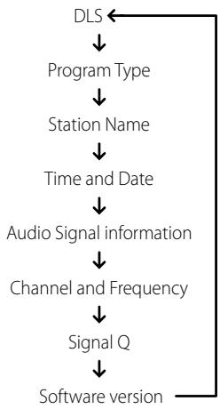
DLS
Dynamic Label Segment (DLS) is the scrolling text supplied by the broadcasting station. It may contain information on music titles or details regarding the program or station.
PROGRAM TYPE
This is a description of the type of broadcast supplied by the station, such as Pop, Rock, Drama and the likes.
STATION NAME
The name or identification of the DAB broadcast station is shown.
TIME AND DATE
The current time and date as supplied by the DAB station are displayed.
AUDIO SIGNAL INFORMATION
Displays the bit rate and audio type (stereo, mono or joint stereo) as transmitted by the DAB broadcast provider. These are set by the broadcaster to suit the type and quality of material being transmitted.
CHANNEL AND FREQUENCY
The channel and frequency of the currently tuned DAB broadcast are displayed.
SIGNAL QUALITY
This displays the digital error rate (0 to 99) of the currently tuned channel - the lower the figure, the better the quality of the received broadcast.
SOFTWARE VERSION
Show the version number of the installed software.
The T 737 is equipped with a data port in the rear panel where an optional "NAD IPD 1 Dock for iPod" (NAD IPD 1) can be plugged in. With the NAD IPD 1 linking the T 737 with your own iPod player, you can enjoy listening to your favorite tracks and playlists as well as view applicable still image and video playback.
You can control your iPod player using the assigned buttons in the T 737 front panel. And with the corresponding AVR 3 remote control function keys, you can select the materials stored in your iPod for playback as well as access many of its functions even from across the room. The optional NAD IPD 1 also charges your iPod player while it is connected to the T 737.
NOTES
- NAD IPD 1 and iPod player are optional and not supplied with your T 737.
- Later variants of the NAD IPD, like NAD IPD 2, are also compatible with T737.
- iPod player functions, features and playback capabilities accessible through T 737 may vary depending on your iPod player model.
- When using the AVR 3 to control the iPod functions, make sure that the Device Selector is set to "MP".
CONNECTING THE OPTIONAL "NAD IPD 1 DOCK FOR iPod" AND iPod PLAYER TO THE T 737
Make sure that all the devices are unplugged before making the connections.
1 Connect the NAD IPD 1's DATA PORT to the corresponding "MP DOCK" data port of the T 737.
2 Connect also the NAD IPD 1's S-video output to T 737's S-VIDEO 4 input and NAD IPD 1's audio out to the T 737's AUDIO 4 input (the default iPod source allocation in the T 737).
3 Dock your iPod player into the NAD IPD 1.
4 After linking together your iPod player, NAD IPD 1 and the T 737, you can now plug them IN to their applicable power sources.
5 With your iPod player, NAD IPD 1 and T 737 all at power ON state, select Source 4 (iPod) of your T 737. The upper line of the VFD will show "iPod Menu".
iPod MENU OPTIONS
There are two menu options for iPod - iPod Menu and Simple Mode. At "iPod Menu", iPod navigation will be done and guided through the OSD of the T 737. At "Simple Mode" everything will be guided through your iPod's own display screen as you would do in normal iPod use.
The following is the procedure to switch between "iPod Menu" and "Simple Mode" options
1 Press and hold [MENU] button in the front panel or AVR 3 for about 3 seconds.
2 "iPod Menu" is selected when the upper line of the VFD shows "iPod Menu" and the lower line of the VFD shows " Playlist". "iPod Menu" is the default menu option.
3 Press and hold [MENU] button again and the upper line of the VFD shows "IPod" and the lower line of the VFD shows "Simple Mode". You are now at Simple Mode.
iPod MENU
At "iPod Menu" mode, there are several available menu options that are similar to what you can find in an iPod player. The OSD shows the following iPod Menu options – Playlists, Artists, Albums, Songs, Podcasts, Genres, Composers and Audiobook. Use [▲/▼] to move up or down the iPod menu selections. Navigate and select through these "iPod Menu" options as you would when operating your iPod player independently.
NOTE
At "iPod Menu", your docked iPod player's click wheel and controls will not be operational. Your iPod player will show in its display the NAD logo. Use the corresponding front panel or AVR 3 buttons to navigate through the "iPod Menu" options.
SIMPLE MODE
At "Simple Mode", refer to your docked iPod player's own display screen to navigate and make full use of its features. Use your docked iPod's own click wheel and controls or the corresponding front panel or AVR 3 buttons to select through the available options as displayed in your iPod player's display screen.
CONTROL FEATURES
Use the following control buttons in navigating through the iPod menu options. These are applicable using either the front panel (if available) or AVR 3 buttons. Since the AVR 3 will be the primary controller in most cases, we will focus on remote-controlled operations. Note that other NAD IPD models, like the NAD IPD 2, have their own remote controls. The controls below also apply to the corresponding buttons of the remote controls of such applicable NAD IPD models.
DISP
During playback, toggle [DISP] key of AVR 3 to show in the VFD upper line the following
- Current iPod playback mode (shuffle, repeat modes)
Song title - Artist Name
Album title
If there is no information available, the display will show "No Song", "No Artist" or "No Album" as applicable.
A
Press [ ] to return to a previous option or menu selection. Press [ ] to move forward an option or make a selection.
#
While at menu options or selection lists, toggle [ / ] to go up or down the options, lists or song titles. Press and hold [ / ] to quickly scroll through the song titles.
ENTER (APPLICABLE ONLY AT SIMPLE MODE)
Press [ENTER] to select an option or start playback.
[14/14]
During playback or PAUSE mode, press and hold [1 / > 1] for fast forward or backward scanning of current song. Press [> ] to skip forward to the next song or [1 ] to skip back to the previous song.
PAUSE [II] / PLAY [▶]
Press PAUSE [II] during playback to stop playback temporarily. Resume play by pressing again [II] (Pause) or [▶] (Play).
LIGHT (FOR DR 1 REMOTE CONTROL OF NAD IPD 2 ONLY)
Press [LIGHT] to turn ON the backlight of your iPod player if it is in idle mode.
MENU (FOR DR 1 REMOTE CONTROL OF NAD IPD 2 ONLY)
Press [MENU] to return to a previous option or menu selection.
RPT (REPEAT) ( IN DR 1)
Toggle to initiate repeat mode as follows
Rep 1 (Repeat One) - repeat one song
Rep All (Repeat All) - repeat all songs
Repeat Off - cancel repeat mode
RAND (RANDOM) ( 已 IN DR 1)
Toggle to initiate playback in random order. There are three random modes
- Shuffle Song, Shuffle Album or Shuffle Off.
NOTE
For other navigation functions, please refer to your iPod player's owner's manual. Depending on the iPod player model, some other functions maybe controlled using the applicable T 737 navigation controls.
TO VIEW VIDEOS OR PHOTOS LOADED IN YOUR iPod
Videos or photos uploaded in your iPod can be viewed directly via the T 737. The following are the conditions/settings to be undertaken to view your iPod's video or photo files.
1 You must be at Simple Mode to access your iPod's video or photo files.
2 Make sure that the "TV Out" setting of your iPod's Video or Photo Settings menu is at "On" mode and appropriate "TV Signal" is chosen.
3 Video or photo file selection and playback procedures are managed directly from your iPod player or by the applicable buttons of the T 737 front panel or AVR 3 remote control.
With the iPod (IPD 1) dock's S-VIDEO OUT and AUDIO OUT ports connected to the T 737's S-VIDEO 4 /AUDIO 4 input, you can now directly enjoy via T 737 your video or photo selections as uploaded in your iPod. Make sure that you select the correct source input of the T 737.
NOTE
iPod player functions, features and playback capabilities accessible through T 737 may vary depending on your iPod player model. Check NAD IPD-1's specifications with regards to specific iPod models it supports.
iPod is a trademark of Apple Inc., registered in the U.S. and other countries.
TROUBLESHOOTING
| CONDITION | POSSIBLE CAUSES | POSSIBLE SOLUTIONS |
| No sound from all channels. | • AC power unplugged. | • Check AC cable connection and outlet. |
| • Power not switched on. | ||
| • Outlet has no power. | ||
| No sound from some channels. | • Faulty/missing cables. | • Check cables. |
| • "Speaker Configuration" channel (s) set to "Off". | • Check "Speaker Configuration" menu. | |
| No sound from surround channels. | • No surround / listening mode is engaged. | • Select appropriate listening mode. |
| • Surround-channels set to "Off" on "Speaker Configuration" menu. | • Correct "Speaker Configurations" or "Speaker Levels" settings. | |
| • Surround-channels level set too low on "Speaker Levels" menu. | ||
| No sound from Subwoofer. | • Subwoofer is off, not powered or improperly connected. | • Power-up subwoofer, check Sub's AC outlet or check connections. |
| • Subwoofer set to "Off" on "Speaker Configuration" menu. | • Correct "Speaker Configuration" or "Speaker Levels" settings. | |
| • Sub level set too low on "Speaker Levels" menu. | ||
| No sound from Center channel. | • Source is a 2/0 (etc.). | • Play a known 5.1-channel recording or select Dolby Pro Logic IIx Music mode. |
| • Dolby Digital or DTS recording without center channel; Center set to "Off" on "Speaker Configuration" menu. | • Correct "Speaker Configuration" or "Speaker Levels" settings. | |
| • Center level set too low on "Speaker Levels" menu. | ||
| No Dolby Digital/DTS. | • Source's digital output is not connected to a T 737 digital input. | • Check connections. |
| • Source component not configured for multichannel digital output. | • Check source component setup. | |
| T 737 does not respond to AVR 3 remote control commands. | • Batteries are flat or incorrectly inserted. | • Check batteries. |
| • IR transmitter window on remote or IR A/V Receiver window on T 737 is obstructed. | • Check IR windows and ensure clear line-of-sight from remote to T 737. | |
| • T 737 front panel is in very bright sunlight or ambient light. | • Reduce sunlight/room lighting. |
NOTE
Restoring your T 737 to its factory defaults: At FM mode, press and hold front panel's LISTENING MODE button until the VFD shows "Factory Reset".
AMPLIFIER SECTION
| Power output, Stereo Mode | 2 x 80 W (ref. 0.08 % THD, 8 Ω) | |
| IHF dynamic power - 8 Ω | 2 x 110 W | |
| 4 Ω | 2 x 160 W | |
| Power output Surround Mode | 7 x 40 W | |
| Total harmonic distortion at rated power | 0.08 % | |
| IM distortion at rated power | 0.08 % | |
| Damping factor, 8 Ω | >60 | |
| Input sensitivity and impedance | 300 mV/47 kΩ | |
| Frequency response | ±0.5 dB (ref. 20Hz - 20 kHz) | |
| Signal/noise ratio, A-weighted | >100 dB (ref. rated power 8Ω) | |
| >90 dB (ref. 1W 8Ω) | ||
| TUNER SECTION | ||
| AM BAND | Tuning range | 522 kHz - 1620 kHz (9 kHz steps, 230V version only) |
| 530 kHz - 1710 kHz (10 kHz steps, 120V version only) | ||
| Usable sensitivity | 60 dBu | |
| Signal/noise ratio | 40 dB | |
| Total Harmonic Distortion | 1.5 % | |
| FM BAND | Tuning range | 87.5 MHz - 108 MHz |
| Usable sensitivity, Mono | 10 dBμ | |
| Signal/noise ratio, Mono | 70 dB | |
| Signal/noise ratio, Stereo | 65 dB | |
| Total Harmonic Distortion, Mono | 0.3 % | |
| Total Harmonic Distortion, Stereo | 0.5 % | |
| Channel Separation | 40 dB | |
| RDS decode sensitivity | 0.2 % | |
| POWER CONSUMPTION | ||
| Idle power | 46W | |
| Standby power | <1W | |
| PHYSICAL SPECIFICATIONS | ||
| Unit Dimensions (W x H x D) | 435 x 167 x 394 mm (Gross) | |
| Net Weight | 12.08 kg | |
| Shipping Weight | 15.10 kg | |
Specifications are subject to change without notice. For updated documentation and features, please log onto www.NADelectronics.com for the latest information about T 737.
Manufactured under license under U.S. Patent #s: 5,451,942; 5,956,674; 5,974,380; 5,978,762; 6,226,616; 6,487,535; 7,003,467; 7,212,872 & other U.S. and worldwide patents issued & pending. DTS, DTS Digital Surround, ES, and Neo6 are registered trademarks and the DTS logos, Symbol and DTS 96/24 are trademarks of DTS, Inc. © 1996-2009 DTS, Inc. All Rights Reserved.
Manufactured under license from Dolby Laboratories.
"Dolby," "Pro Logic", and the double-D symbol are registered trademarks of Dolby Laboratories.
HDMI, the HDMI logo and High-Definition Multimedia Interface are trademarks or registered trademarks of HDMI Licensing LLC.
The XM name, XM Ready and related logos are registered trademarks of XM Satellite Radio Inc.
This product incorporates copyright protection technology that is protected by method claims of certain U.S. patents and other intellectual property rights owned by Macrovision Corporation and other rights owners. Use of this copyright protection technology must be authorized by Macrovision Corporation, and is intended for home and other limited viewing uses only unless otherwise authorized by Macrovision Corporation. Reverse engineering or disassembly is prohibited.

www.NADelectronics.com
©2009 NAD ELECTRONICS INTERNATIONAL
A DIVISION OF LENBROOK INDUSTRIES LIMITED
All rights reserved. NAD and the NAD logo are trademarks of NAD Electronics International, a division of Lenbrook Industries Limited. No part of this publication may be reproduced, stored or transmitted in any form without the written permission of NAD Electronics International.