
T175 HD - AV receiver NAD - Free user manual and instructions
Find the device manual for free T175 HD NAD in PDF.
| Product type | Audio-video receiver |
| Brand | NAD |
| Model | T175 HD |
| Dimensions (W x H x D) | 435 x 170 x 410 mm |
| Weight | 14.5 kg |
| Power supply | 220-240 V~, 50/60 Hz |
| Power consumption | 100 W (operating), < 0.5 W (standby) |
| Output power | 7 x 100 W (8 ohms, 20 Hz-20 kHz, THD 0.08 %) |
| Supported audio formats | Dolby TrueHD, Dolby Digital Plus, DTS-HD Master Audio, DTS 96/24, multi-channel PCM |
| Video inputs | 5 HDMI, 2 component, 4 composite |
| Video outputs | 2 HDMI (1 with ARC), 1 component, 1 composite |
| Audio inputs | 7 RCA (1 phono), 2 optical, 2 coaxial, 1 stereo mini-jack |
| Audio outputs | 7 pairs of speaker terminals, 2 subwoofer (RCA), 1 headphone (6.35 mm jack) |
| Main features | 7.1 amplification, HD decoders, 1080p video upscaling, bi-amping compatibility, Pure Audio mode, speaker calibration |
| Maintenance and cleaning | Regular dusting with a soft dry cloth. Do not use solvents or abrasive cleaners. |
| Safety | Do not open the device. Disconnect before any cleaning. Avoid moisture and heat sources. |
| Spare parts and repairability | Fuses, filters and power supply modules available from NAD authorized after-sales service. |
| Included accessories | Remote control, batteries, power cable, FM/AM antenna, calibration microphone |
Frequently Asked Questions - T175 HD NAD
User questions about T175 HD NAD
0 question about this device. Answer the ones you know or ask your own.
Ask a new question about this device
Download the instructions for your AV receiver in PDF format for free! Find your manual T175 HD - NAD and take your electronic device back in hand. On this page are published all the documents necessary for the use of your device. T175 HD by NAD.
USER MANUAL T175 HD NAD
- Read instructions - All the safety and operating instructions should be read before the product is operated.
- Retain instructions - The safety and operating instructions should be retained for future reference.
- HeedWarnings - All warnings on the product and in the operating instructions should be adhered to.
- Follow Instructions - All operating and use instructions should be followed.
- Cleaning - Unplug this product from the wall outlet before cleaning. Do not use liquid cleaners or aerosol cleaners. Use a damp cloth for cleaning.
- Attachments - Do not use attachments not recommended by the product manufacturer as they may cause hazards.
- Water and Moisture - Do not use this product near water-for example, near a bath tub, wash bowl, kitchen sink, or laundry tub; in a wet basement; or near a swimming pool; and the like.
- Accessories - Do not place this product on an unstable cart, stand, tripod, bracket, or table. The product may fall, causing serious injury to a child or adult and serious damage to the product. Use only with a cart, stand, tripod, bracket, or table recommended by the manufacturer, or sold with the product. Any mounting of the product should follow the manufacturer's instructions, and should use a mounting accessory recommended by the manufacturer.

Cart - A product and cart combination should be moved with care. Quick stops, excessive force, and uneven surfaces may cause the product and cart combination to overturn.
- Ventilation - Slots and openings in the cabinet are provided for ventilation to ensure reliable operation of the product and to protect it from overheating. These openings must not be blocked or covered. The openings should never be blocked by placing the product on a bed, sofa, rug, or other similar surface. This product should not be placed in a built-in installation such as a bookcase or rack unless proper ventilation is provided or the manufacturer's instructions have been adhered to.
- Power Sources - This product should be operated only from the type of power source indicated on the marking label and connected to a MAINS socket outlet with a protective earthing connection. If you are not sure of the type of power supply to your home, consult your product dealer or local power company.
- Power-Cord Protection - Power-supply cords should be routed so that they are not likely to be walked on or pinched by items placed upon or against them, paying particular attention to cords at plugs, convenience receptacles, and the point where they exit from the product.
13.Mains Plug - Where the mains plug or an appliance coupler is used as the disconnect device, the disconnect device shall remain readily operable. - Outdoor Antenna Grounding - If an outside antenna or cable system is connected to the product, be sure the antenna or cable system is grounded so as to provide some protection against voltage surges and built-up static charges. Article 810 of the National Electrical Code, ANSI/NFPA 70, provides information with regard to proper grounding of the mast and supporting structure, grounding of the lead-in wire to an antenna discharge unit, size of grounding conductors, location of antenna discharge unit, connection to grounding electrodes, and requirements for the grounding electrode.
NOTE TO CATV SYSTEM INSTALLER
This reminder is provided to call the CATV system installer's attention to Section 820-40 of the NEC which provides guidelines for proper grounding and, in particular, specifies that the cable ground shall be connected to the grounding system of the building, as close to the point of cable entry as practical.
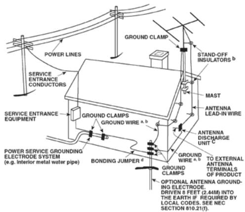
- Lightning - For added protection for this product during a lightning storm, or when it is left unattended and unused for long periods of time, unplug it from the wall outlet and disconnect the antenna or cable system. This will prevent damage to the product due to lightning and power-line surges.
- Power Lines - An outside antenna system should not be located in the vicinity of overhead power lines or other electric light or power circuits, or where it can fall into such power lines or circuits. When installing an outside antenna system, extreme care should be taken to keep from touching such power lines or circuits as contact with them might be fatal.
- Overloading - Do not overload wall outlets, extension cords, or integral convenience receptacles as this can result in a risk of fire or electric shock.
- Flame Sources - No naked flame sources, such as lighted candles, should be placed on the product.
- Object and Liquid Entry - Never push objects of any kind into this product through openings as they may touch dangerous voltage points or short-out parts that could result in a fire or electric shock. Never spill liquid of any kind on the product.
- Headphones - Excessive sound pressure form earphones and headphones can cause hearing loss.
- Damage Requiring Service - Unplug this product from the wall outlet and refer servicing to qualified service personnel under the following conditions:
a. When the power-supply cord or plug is damaged.
b. If liquid has been spilled, or objects have fallen into the product.
c. If the product has been exposed to rain or water.
d. If the product does not operate normally by following the operating instructions. Adjust only those controls that are covered by the operating instructions as an improper adjustment of other controls may result in damage and will often require extensive work by a qualified technician to restore the product to its normal operation.
e. If the product has been dropped or damaged in any way.
f. When the product exhibits a distinct change in performance—this indicates a need for service.
-
Replacement Parts - When replacement parts are required, be sure the service technician has used replacement parts specified by the manufacturer or have the same characteristics as the original part. Unauthorized substitutions may result in fire, electric shock, or other hazards.
-
Battery Disposal - When disposing of used batteries, please comply with governmental regulations or environmental public instruction's rules that apply in your country or area.
- Safety Check - Upon completion of any service or repairs to this product, ask the service technician to perform safety checks to determine that the product is in proper operating condition.
- Wall or Ceiling Mounting - The product should be mounted to a wall or ceiling only as recommended by the manufacturer.
WARNING

The lightning flash with arrowhead symbol, within an equilateral triangle, is intended to alert the user to the presence of uninsulated "dangerous voltage" within the product's enclosure that may be of sufficient magnitude to constitute a risk of electric shock to persons

The exclamation point within an equilateral triangle is intended to alert the user to the presence of important operating and maintenance (servicing) instructions in the literature accompanying the appliance.

WARNING: TO REDUCE THE RISK OF FIRE OR ELECTRIC SHOCK, DO NOT EXPOSE THIS APPARATUS TO RAIN OR MOISTURE AND OBJECTS FILLED WITH LIQUIDS, SUCH AS VASES, SHOULD NOT BE PLACED ON THIS APPARATUS.
THE EQUIPMENT MUST BE CONNECTED TO AN EARTHED MAINS SOCKET-OUTLET.
CAUTION REGARDING PLACEMENT
To maintain proper ventilation, be sure to leave a space around the unit (from the largest outer dimensions including projections) than is equal to, or greater than shown below.
Left and Right Panels: 10 cm
Rear Panel: 10 cm
Top Panel: 50 cm
IMPORTANT INFORMATION TO UK CUSTOMERS
DO NOT cut off the mains plug from this equipment. If the plug fitted is not suitable for the power points in your home or the cable is too short to reach a power point, then obtain an appropriate safety approved extension lead or consult your dealer. If nonetheless, the mains plug is cut off, REMOVE THE FUSE and dispose of the PLUG immediately, to avoid possible shock hazard by inadvertent connection to the mains supply. If this product is not provided with a mains plug, or one has to be fitted, then follow the instructions given below:
IMPORTANT
DO NOT make any connection to the larger terminal which is marked with the letter 'E' or by the safety earth symbol or colored GREEN or GREEN AND YELLOW. The wires in the mains lead on this product are colored in accordance with the following code:
BLUE-NEUTRAL
BROWN-LIVE
As these colors may not correspond with the colored markings identifying the terminals in your plug, proceed as follows:
- The BLUE wire must be connected to the terminal marked with the letter 'N' or colored BLACK.
- The BROWN wire must be connected to the terminal marked with the letter 'L' or colored RED
- When replacing the fuse, only a correctly rated and approved type should be used, and be sure to re-fit the fuse cover.
IF IN DOUBT CONSULT A COMPETENT ELECTRICIAN.

This product is manufactured to comply with the radio interference requirements of EEC DIRECTIVE 2004/108/EC.
NOTES ON ENVIRONMENTAL PROTECTION

At the end of its useful life, this product must not be disposed of with regular household waste but must be returned to a collection point for the recycling of electrical and electronic equipment. The symbol on the product, user's manual and packaging point this out.
The materials can be reused in accordance with their markings. Through re-use, recycling of raw materials, or other forms of recycling of old products, you are making an important contribution to the protection of our environment.
Your local administrative office can advise you of the responsible waste disposal point.
RECORD YOUR MODEL NUMBER (NOW, WHILE YOU CAN SEE IT)
The model and serial number of your new T 175 are located on the back of the cabinet. For your future convenience, we suggest that you record these numbers here:
Model number:
Serial number:
TABLE OF CONTENTS
IMPORTANT SAFETY INSTRUCTIONS 2
INTRODUCTION
ABOUT THE T 175 5
E.A.R.S. AND DIGITAL SURROUND 5
EASE OF USE 5
INTEGRATION 5
ZONE. 5
RS 232. 5
UPGRADABILITY 5
ABOUT THE HTRC 1 SYSTEM REMOTE CONTROL .5
GETTING STARTED 6
WHAT'S IN THE BOX 6
CHOOSING A LOCATION 6
QUICK START 7
IDENTIFICATION OF CONTROLS
FRONT PANEL. 8
REAR PANEL 10
OPERATION
USING THE T 175 - MAIN MENU. 13
ABOUT THE ON-SCREEN DISPLAY (OSD) 13
MAIN MENU 13
LISTENING MODE 13
ADJUSTING LISTENING MODES 14
DSP OPTIONS 15
TONE CONTROLS. 16
PICTURE CONTROLS. 16
ZONE CONTROLS. 17
USING THE T 175-SETUP MENU. 18
SETUP MENU 18
VIDEO SETUP 18
SOURCE SETUP 19
SOURCE SETUP (NORMAL VIEW) 19
SOURCE SETUP (TABLE VIEW). 21
iPod SETUP 21
SPEAKER SETUP 21
AUDYSSEY AUTO CALIBRATION 22
SPEAKER CONFIGURATION 24
SPEAKER LEVELS 24
SPEAKER DISTANCE 25
ADJUSTING THE VOLUME 25
ADJUSTING CHANNEL LEVELS'ON THE FLY' 26
ZONE SETUP 26
TRIGGER SETUP 27
LISTENING MODE SETUP 27
DOLBYSETUP 29
DTS SETUP 29
DTS SURROUND MODES 29
ENHANCED STEREO 30
DISPLAY SETUP 30
A/V PRESETS 31
USING THE T 175 - AM/FM/DB/iPod 34
LISTENING TO AM/FM RADIO. 34
ABOUTUSERNAMES 35
ABOUT RDS 35
LISTENING TO XM RADIO. 35
LISTENING TO DAB RADIO. 36
CONNECTING THE DAB MODULE 36
DAB OPERATION 36
SERVICE LIST 37
DAB TUNER MODE 37
STATION ORDER 37
DRC 37
MANUAL SCAN 37
PRUNE LIST 37
RESET 38
INFORMATION SETTINGS. 38
LISTENING TO YOUR iPod PLAYER 39
NAD IPD 2. 40
USING THE HTRC 1 REMOTE CONTROL. 41
IDENTIFICATION OF CONTROLS 41
INTRODUCTION 41
GETTINGFAMILIARWITHTHETHRC1 41
NAVIGATION OF THE HTRC 1 CONTROLS 42
HTRC1SETUPMENU 42
BATTERY 42
BACK LIGHT SENSITIVITY (B LIGHT) 42
LIBRARY 43
LEARN. 43
PUNCH-THROUGH (Pun Thr). 44
COPY 45
DELETE 46
RENAME 46
MACRO. 46
RESET 47
USING THE ZR 4 REMOTE CONTROL 48
REFERENCE
TROUBLESHOOTING 49
SPECIFICATIONS 50
THANK YOU FOR CHOOSING NAD.
The T 175 A/V Tuner Preamplifier is a technologically advanced and highly capable product — yet we have invested great effort in making it simple and easy to use. The T 175 delivers a range of genuinely useful options for surround sound and stereo listening alike, using powerful digital signal processing and superbly accurate digital-audio circuitry. However, we have also been careful to ensure that the T 175 is as musically transparent, faithful to every video detail and spatially accurate as possible, incorporating much of what we've learned from a quarter-century's experience designing audio, video and home-theater components. As with all our products, NAD's
"Music First" design philosophy guided the T 175's design, such that it can confidently promise you both state-of-the-art surround home-theater and audiophile-quality music listening for years to come.
We encourage you to take a few minutes now to read right through this manual. Investing a little time here at the outset might save you a good deal of time later, and is by far the best way to ensure that you make the most of your investment in the T 175, and get the most from this powerful and flexible home-theater component.
One more thing: We urge you to register your T 175 ownership on the NAD Worldwide Web site:
http://NADelectronics.com/warranty
For warranty information contact your local distributor.
Though the T 175 is among the most technically sophisticated A/V Tuner Preamplifier, we worked hard to make it one of the most musically transparent home-theater components available as well; this is what we mean by NAD's "Music First" design philosophy. Here are just few examples:
- High-performance components used throughout the A/V Tuner Preamplifier's analog audio circuits maximize quality from all sources, including multi-channel analog sources such as DVD-Audio and SACD.
Audio pre-out jacks make potential expansion as flexible as possible..
Zone pre-amp and video feed with assignable 12 V DC trigger control. - An RS-232 port for advanced zone control and software update through a Windows® compatible PC.
- Gold-surfaced connectors are employed throughout to ensure maximum signal integrity.
E.A.R.S. AND DIGITAL SURROUND
A key element of the T 175's unique musical aptitude is NAD's proprietary Enhanced Ambience Recovery System (EARS). In sharp contrast to many "ambience-synthesis" music-surround modes, EARS exploits the T 175's substantial DSP power to route the ambient content that is "encrypted" in virtually all natural-acoustic recordings to the appropriate main, center and surround speakers, without resorting to artificially generated reflections or regeneration. EARS' natural ambience yields a subtle but exceptionally effective surround mode that naturally enhances the spatial presentation in a fashion suitable for serious music listening.
Dolby Pro Logic IIx Music and DTS Neo: 6 Music modes can also create enjoyable experience from 2-channel sources.
On the digital side, the T 175 combines extraordinarily high-speed DSP processing employing one of the most advanced high-speed DSP "engines" available, with fully 24-bit, 192kHz -sampling-capable D/A converters for all channels. A single, high-precision master clock synchronizes all digital circuits to eliminate the timing errors ("jitter") that otherwise compromise sonics. The result is legitimately state-of-the-art surround decoding from Dolby Digital and DTS sources, and 6.1/7.1-channel reproduction, with genuinely superior sound quality in all modes.
EASE OF USE
Despite the effort NAD has invested in the T 175 A/V Tuner Preamplifier's sonic performance, we expended no less in making it powerfully easy to use. Its design is uniquely simple for so sophisticated a component, and the HTRC 1 universal remote control is equally understandable, as are the T 175's own front-panel and on-screen displays. Its simple yet powerful system of "presets" permits you to fine-tune your listening setup for different conditions, sources, or listeners, and to recall these multiple parameters with a single key press.
INTEGRATION
The T 175 offers extensive, flexible system-integration options through its configurable DC trigger outputs and input, and its standard-protocol IR communications links. The DC trigger outputs can be assigned to either Local and/or Zone locations.
ZONE
The T 175 is equipped with three configurable Zones that make full use of video and pre-amp level audio outputs. The ZR 4 remote control will allow you complete access to Zone 2 applications including access to volume On/Off and all sources inputs. Zone 3 and Zone 4 could be configured and managed at the appropriate Zone OSD menu using the front panel navigations keys as well as the corresponding keys on the HTRC 1 remote control.
RS 232
Flexible system configuration is possible with the RS-232 interface and NAD's proprietary Windows® compatible software. We are also certified partners with AMX and Crestron and fully support these external devices.
This interface allows complete remote control of the T 175 from any remote location via the PC. Complete remote control functionality is available to the user by interface software. See your NAD audio specialist for further information.
UPGRADABILITY
The T 175 permits flexible system growth via individually accessible pre-out and main-in jacks for all channels. We have made the more likely scenario of software upgrades easy to accomplish via the high speed RS-232 port on the rear panel of the T 175. Owners who register their T 175 on our international web site www.NADelectronics.com will be advised of updates. Some of these may be free of charge, and some may require royalty payments depending on the type of upgrade. The advanced user will be able to perform these upgrades by downloading files from our web site, via e-mail and installing them by connecting the T 175 to a PC. Alternatively the dealer from whom you purchased your T 175 should be able to assist in performing these upgrades.
ABOUT THE HTRC 1 SYSTEM REMOTE CONTROL
Packed with your T 175 is the NAD HTRC 1 remote control, a full-system remote especially designed for easy use and understanding. Be sure to read the section "Using the HTRC 1 Remote Control," to familiarize yourself with the remote's layout and operations before proceeding to setup your T 175. You may opt to use your HTRC 1 as your primary way to command your entire A-V system. The HTRC 1 can be employed to operate additional NAD or other-brand components such as a DVD/CD player, television, satellite/HDTV tuner, VCR, or virtually anything else that operates via standard infrared remote.
WHAT'S IN THE BOX
Packed with your T 175 you will find
An AM loop antenna
A FM ribbon-wire antenna with balun
- A removable AC cable (if you wish, any IEC-standard AC cable of suitable wattage may be substituted)
The HTRC 1 remote control with 4 (four) AA batteries
The ZR 4 zone remote control with 3V CR2025 battery
This owner's manual
SAVE THE PACKAGING
Please save the box and all of the packaging in which your T 175 arrived. Should you move or otherwise need to transport your T 175, this is by far the safest container in which to do so. We've seen too many otherwise perfect components damaged in transit for lack of a proper shipping carton, so please: Save that box!
CHOOSING A LOCATION
Choose a location that is well ventilated (with at least several inches to both sides and behind), and that will provide a clear line of sight, within 25 feet/8 meters, between the T 175's front panel and your primary listening/viewing position—this will ensure reliable infrared remote control communications. The T 175 generates a modest amount of heat, but nothing that should trouble adjacent components.
It is perfectly possible to stack the T 175 on top of other components, but the reverse usually should be avoided.
QUICK START
Packed with your T 175 is a Quick Start Guide that will guide you through typical setup configurations in combination with your ancillary devices. The Quick Start Guide also features the contents of your T 175 package as well as start up procedures.
The T 175 is defaulted to the following settings:
| Source | Audio Input | Video Input |
| Source 1 | HDMI 1 IN/ Audio 1 IN | HDMI 1 IN |
| Source 2 | Optical 2 IN/ Audio 2 IN | Component Video 2 IN |
| Source 3 | Coaxial 3 IN/ Audio 3 IN | S Video 3 IN |
| Source 4 | Audio 4 IN | Video 4 IN |
| iPod | Audio 5 IN | S-Video 5 IN |
| Source 7 | 7.1 Input | Component Video 3 IN |
| Front Input | Optical Front Input/ Audio Front Input | S-Video Front IN |
| Media Player | Audio MP input | |
| Tuner |
For Video output, select the highest video quality format available on your TV/Monitor and utilize this for your Monitor OUT connection from the T 175 to the TV/Monitor. In most cases, this would be HDMI but for other TV/Monitor without HDMI input, the best connection in order of best video quality would be Component Video, S-Video and Composite video input.
To modify the above default settings and for a better understanding of source setting and combinations, please refer to the section on 'Source Setup' of the Setup Menu discussion.
NOTE
Digital input will always take precedence over analog audio input even if both are present.
FRONT PANEL
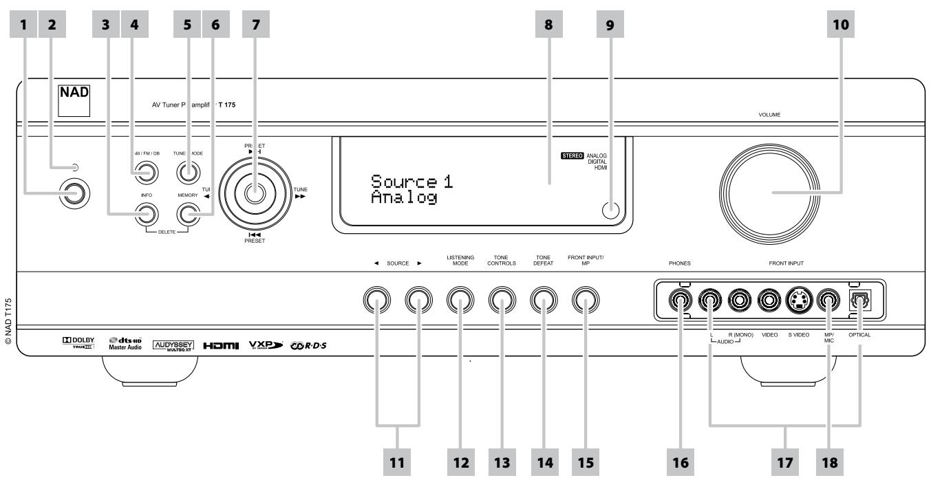
1 STANDBY BUTTON: Press this button or the HTRC 1 remote's [ON] button to switch ON the T 175. The Standby LED indicator will turn from amber to blue and illuminate the VFD. Pressing the standby button again turns the unit back to standby mode.
The T 175 can also be switched ON from standby mode by pressing any of the front panel buttons. When both Main and Zones are ON, press and hold this button for more than five seconds to place them at standby mode.
NOTES
- The rear panel POWER switch must be in the ON position for the Standby button to activate.
- If Auto Trigger IN at Trigger Setup menu is assigned to 'Main' or 'All' and the TRIGGER switch is set to 'AUTO' mode, the standby button in the front panel as well as the corresponding ON/OFF function keys in the HTRC 1 remote control will be disabled effectively handling this function to an external controller. Switch TRIGGER to 'OFF' to maintain normal power ON/OFF function procedures. (See section also about "Trigger Setup" under the "Setup Menu" discussions.
2 STANDBY LED : This indicator will light up amber when the T 175 is in standby state. When the T 175 main or zones are in the ON state, this indicator will illuminate blue. In the unlikely event that the T 175 switches to protection state, then this indicator will illuminate red. When infrared command from the HTRC 1 is received, this indicator will also flash momentarily.
3 INFO: Repeatedly toggle this button (press/hold first if in Tuner mode and then toggle) to display both at the Vacuum Fluorescent Display (VFD) and On-Screen Display (OSD) the following - Current Source, Volume level, Listening mode, Audio Source Format, Audio Codec, Video Mode and active Zones with their corresponding Source Inputs. While at Tuner mode, toggle this button to cycle through Preset Name, RDS name and RDS text.
4 AM/FM/DB : Toggle this button to select either AM, FM, DAB (230V version only) or XM (120V version only) tuner functions.
5 TUNER MODE: In FM mode, this button will toggle between FM Stereo and FM mono. Select FM Mono (FM stereo and FM Mute icons at VFD are extinguished) for stations that have too much interference or are too weak. In DAB (230V version only) or XM (120V version only) radio, this button enables the digital radio menu in conjunction with the Navigation button and Enter buttons.
6 MEMORY : Press this button to store tuned AM, FM and digital radio stations to the T 175's 40 preset-memory locations. One can store a mix of any AM, FM and digital radio stations to the 40 available presets.
7. NAVIGATION and ENTER buttons: These buttons are used to navigate the T 175 OSD, Tune Scan Forward▶ and Tune Scan Reverse▶, Preset Skip Forward▶ and Preset Skip Reverse▶ as well as navigation of DAB (230V version only), XM (120V version only) tuner functions and iPod.
8 VACUUM FLUORESCENT DISPLAY (VFD): Displays visual information about the current settings like the active Source, volume level, listening mode, audio format, applicable RDS/XM/DAB as well as iPod-related display information and other related indicators. Refer also to the item about DISPLAY SETUP under the USING THE T 175 - SETUP MENU segment of the OPERATION section.
9 REMOTE SENSOR: Point the HTRC 1 remote control at the remote sensor and press the buttons. Do not expose the remote sensor of the T 175 to a strong light source such as direct sunlight or illumination. If you do so, you may not be able to operate the T 175 with the remote control. Distance: About 23ft (7m) from the front of the remote sensor. Angle: About 30^ in each direction of the front of the remote sensor.
10 VOLUME: Use this control to adjust the overall loudness of the signal output at AUDIO PRE-OUT. The default volume level is -20dB. The VOLUME knob is also used to increment / decrement other adjustable parameters like Tone Controls.
11
12 LISTENING MODE: Toggle to select through the various Listening mode options. Depending on the format of the currently selected input (digital or analog, stereo or multichannel), various listening modes are available. Refer also to the item about LISTENING MODE under the USING THE T 175 - MAIN MENU segment of the OPERATION section.
13 TONE CONTROLS: Press to adjust TREBLE control using the VOLUME knob over a ± 10dB range. Press again to adjust BASS control and a third time for DIALOG control. See also section about 'Tone Controls' under 'Setup Menu' discussions.
14 TONE DEFEAT : Tone Controls are enabled or disabled by pressing this button. Tone controls are bypassed at 'Tone Defeat' while at 'Tone Active', the tone controls are enabled again. See also section about 'Tone Controls' under 'Setup Menu' discussions.
15 FRONT INPUT/MP: Use this button to directly select Front Input and Media Player. Toggle button to switch between Front Input and Media Player input.
16 PHONES: Accepts stereo headphone using a standard 1/4-inch stereo phone plug (use a suitable adapter for headphones equipped with a smaller plug). For headphone listening, the Front speakers must be set to "Large" at the 'Speaker Configuration' of the Speaker Setup item at the Setup Menu, otherwise headphone bass response will be restricted. Plugging in headphones will automatically switch the T 175 to Stereo, Stereo Downmix or Analog Bypass modes.
17 FRONT INPUT jacks: Use these convenience jacks for occasional sources such as a camcorder, tape player, video game console, any analog audio or optical digital audio and composite or S-Video video sources. If your source has a single audio out jack only or is marked 'mono output', plug this into the T 175's Front 'R (Mono)' input. On the other hand, if your source has two output jacks indicative of stereo output, insert both jacks into the T 175's corresponding Front 'L' and 'R (Mono)' input to achieve stereo output as well.
18 MP/MIC input : Connect your MP3's standard stereo phone jack to this input. This is the same input where Audyssey microphone jack is connected (See also discussion about 'Audyssey Auto Calibration').
REAR PANEL
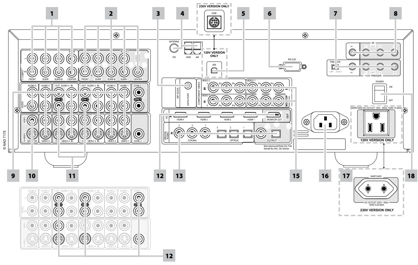
1 7.1 CH INPUT: Connect to the corresponding analog audio outputs of a multichannel source component such as a DVD-Audio or multichannel-SACD player or external multichannel decoder (disc copy protected formats only allow analog signal transfer). Typically, these sources will produce 5.1-channel output, in which case the Surround Back jacks are left unconnected. The signals present at these jacks may be heard by selecting Source 7 (External 7.1 audio input is defaulted to this Source).
There is no bass-management or other processing (other than master-volume control) available to this 7.1 channel input. While the multi-channel audio output of a DVD-Video player can be connected to these jacks, using the T 175's own Dolby Digital and DTS decoding and digital-analog converters via a digital connection will usually produce superior results.
2 AUDIO PRE-OUT: Connect FRONT L, FRONT R, CENTER, SURR R, SURR L, SURR-BL and SURR-BR to the corresponding channel input of a power amplifier or amplifiers driving the applicable speakers.
Unlike the full range channels, there is no power amplifier built into the T 175 for a subwoofer. Connect the SUBW 1 or SUBW 2 output or both to powered ("active") subwoofer or to power amplifier channels driving a passive system.
3 MP DOCK: The T 175 is equipped with a data port in the rear panel where an optional NAD IPD (NAD IPD Dock for iPod), NAD IPD 2 and later variants can be plugged in. Connect the 'MP DOCK (DATA PORT)' jack of the T 175 to the corresponding 'DATA PORT' socket of the optional NAD IPD model. Refer also to the item about "LISTENING TO YOUR iPod PLAYER" under the "USING THE T 175 - AM/FM/DB/iPod" segment of the "OPERATION" section.
NOTE
The external "NAD IPD Dock for iPod" (NAD IPD) model is not supplied with your T 175.
4 FM, AM ANTENNA INPUT: The supplied wire "dipole" FM antenna will connect to the FM connector using the supplied "balun" adapter. It will usually work best when mounted on a vertical surface such as a wall, with arms fully outstretched forming a horizontal "T" perpendicular to the origin point of the signal.
Connect the supplied AM loop antenna to these terminals. If an external AM antenna is used, make connections to the AM and GND terminals in accordance with the instructions supplied with the antenna.
5 XM MODULE INPUT (120V version only): Connect XM radio cable to this socket. Follow the instructions that came with your XM radio. With XM radio, there are more than 100 channels of music, news, sports, comedy, talk and entertainment. You will find that the coverage is continent wide. The music quality is digital with many commercial-free music channels.
NOTE
The external XM radio is not supplied with your T 175.
DAB MODULE INPUT (230V version only): Plug-in the other end of the Mini-Din connector from the NAD DAB Adaptor DB 1 module output port into this socket. The T 175 is compatible only with NAD DAB Adaptor DB 1 so check with your NAD dealer for this module's availability. With DAB, you can receive CD-like quality programs without any annoying interference and signal distortion.
NOTE
The external "NAD DAB Adaptor DB 1 module" is not supplied with your T 175.
6 RS-232: Connect this interface via RS-232 serial cable (not supplied) to any Windows® compatible PC to allow remote control of the T 175 through NAD's proprietary PC software or other compatible external controllers. Please log on to www.nadelectronics.com/software for the latest PC interface control software. NAD is a certified partner of AMX and Crestron and fully supports these external devices. See your NAD audio specialist for more information
7 +12V TRIGGER OUT: There are three configurable +12V TRIGGER OUTPUT. Use a 3.5mm mini-jack connector to pass +12 volts at a maximum current of 50 milliamps to auxiliary equipment such as a multichannel amplifier or subwoofer. The center conductor (hot) of the 3.5mm jack is the control signal. The outside conductor (shield) is the ground return-path.
TRIGGER IN accepts 12V Trigger output of compatible components such as power controllers and home automation devices. TRIGGER OFF/AUTO: When at AUTO position, the T 175 selects the 12V Trigger Input to turn ON (if so assigned at the "Trigger Setup" menu) and at the same time disables the HTRC 1 and front panel's ON/OFF function. When at OFF position, the trigger input is disabled.
WARNING
If Auto Trigger IN at Trigger Setup menu is assigned to 'Main' or 'All' and the TRIGGER switch is set to 'AUTO' mode, the standby button in the front panel as well as the corresponding ON/OFF function keys in the HTRC 1 remote control will be disabled effectively handling this function to an external controller. Switch TRIGGER to 'OFF' to maintain normal power ON/OFF function procedures.
See discussion on 'Trigger Setup' at the 'Setup Menu' literature for guidelines on how to configure TRIGGER IN/OUT.
8 IR IN/OUT: These mini-jacks accept and output remote-controlled codes in electrical format, using industry-standard protocols, for use with "IR-repeater" and multi-room systems and related technologies.
IR IN: This input is connected to the output of an IR (infrared) repeater (Xantech or similar) or the IR output of another component to allow control of the T 175 from a remote location.
IR OUT 2: When connected to the IR IN of an ancillary equipment, direct the ancillary equipment's own remote control to the T 175's infrared receiver to command or control the linked unit.
IR IN and IR OUT 3: Connect the T 175's IR IN to the IR OUT of an ancillary equipment. Connect also the T 175's IR OUT 3 to another equipment with IR IN feature. With this setup, the T 175 acts as an "IR-repeater" allowing the equipment connected to the T 175's IR IN control or command of the other equipment linked to the T 175's IR OUT 3.
IR OUT 1: In conjunction with IR IN, IR OUT 1 can be used as an "IRrepeater" just like the IR OUT 3 as described above. It can also stand alone as an IR OUT similar to that of IR OUT 2 function.
All NAD products with IR IN/IR OUT features are fully compatible with the T 175. For non-NAD models, please check with your other product's service specialists as to their compatibility to the T 175's IR features.
9 AUDIO 1-5 IN/VIDEO 1-5 IN/S-VIDEO 1-5 IN, AUDIO 6 IN: These comprise the T 175's principal input. Connect S-Video, composite video, and analog stereo audio input ports to source components such as DVD players and HDTV/satellite tuners.
AUDIO 3-4 IN/VIDEO 3-4 IN/S-VIDEO 3-4 IN may be used with recording components such as videocassette or DVD-recorders by connecting these components' record-output to the corresponding T 175 AUDIO 3 IN/VIDEO 3 IN/S-VIDEO 3 IN or AUDIO 4 IN/VIDEO 4 IN/S-VIDEO 4 IN jacks. AUDIO 3 IN/VIDEO 3 IN/S-VIDEO 3 IN or AUDIO 4 IN/VIDEO 4 IN/S-VIDEO 4 IN may freely be used for play-only components, in which case their corresponding OUT jacks would remain unconnected. Refer also to AUDIO 3 OUT/VIDEO 3 OUT/S-VIDEO 3 OUT, AUDIO 4 OUT/VIDEO 4 OUT/S-VIDEO 4 OUT discussion below.
AUDIO 6 is ideal for the connection of the analog output of line-level audio sources like a CD player or Stereo tuner.
10 MONITOR (S-VIDEO,VIDEO): Connect to the video input of a monitor/television using quality dual-RCA and/or S-Video cables designed for video signals. In general, the S-Video connection is superior and should be used if your TV/monitor provides the corresponding input.
REAR PANEL
11 AUDIO 3-4 OUT/VIDEO 3-4 OUT/S-VIDEO 3-4 OUT: Connect the T 175's AUDIO 3 OUT/VIDEO 3 OUT/S-VIDEO 3 OUT or AUDIO 4 OUT/VIDEO 4 OUT/S-VIDEO 4 OUT ports to the analog audio/video input of recording components such as cassette deck, DVD recorder or an outboard audio/video processor. Connect the T 175's AUDIO 3 IN/VIDEO 3 IN/S-VIDEO 3 IN or AUDIO 4 IN/VIDEO 4 IN/S-VIDEO 4 IN ports to the component's corresponding output.
The signal present at these T 175 AUDIO/VIDEO OUT jacks is determined by the source last selected via the front panel Source keys or the HTRC 1's input select keys with the exception of Source 3 or Source 4. There will be no output at AUDIO 3 OUT/VIDEO 3 OUT/S-VIDEO 3 OUT when Source 3 (AUDIO 3 IN/VIDEO 3 IN/SVIDEO 3 IN) is selected. Likewise, there will be no output at AUDIO 4 OUT/VIDEO 4 OUT/S-VIDEO 4 OUT when Source 4 (AUDIO 4 IN/VIDEO 4 IN/SVIDEO 4 IN) is the active source input. This prevents feedback through the recording component thereby preventing possible damage to your speakers.
When configured, AUDIO 3 OUT/VIDEO 3 OUT/S-VIDEO 3 OUT and AUDIO 4 OUT/VIDEO 4 OUT/S-VIDEO 4 OUT are the same assigned ports for Zone 3 and Zone 4 respectively. See also Zone output description below.
12 ZONE 2, ZONE 3, ZONE 4: Sends zone selected audio and video output sources to the corresponding audio and video input of another separate zone. Use high quality patch cables to reduce noise pickup over long distance runs. For a better understanding of zone settings, study below the section about 'Zone Controls' of the 'Main Menu' discussion as well as the item about 'Zone Setup' under the 'Setup Menu' literatures.
NOTE
The ZR 4 remote control will only control Zone 2 applications. Zone 3 and Zone 4 could be configured and managed at the appropriate Zone OSD menu using the front panel navigations buttons as well as the corresponding keys on the HTRC 1 remote control.
13 HDMI (HDMI 1-4, HDMI MONITOR OUT): Connect HDMI inputs to the HDMI OUT connectors of source components such as DVD/BD player or HDTV satellite/cable box. Connect the HDMI Monitor OUT to a HDTV or projector with HDMI input.
WARNING
Before connecting and disconnecting any HDMI cables, both the T 175 and the ancillary source must be powered OFF and unplugged from the AC outlet. Failure to observe this practice may cause permanent damage to all equipment connected via HDMI sockets.
14 DIGITAL AUDIO IN (OPTICAL 1-3, COAXIAL 1-3): Connect to the optical or coaxial S/PDIF-format digital output of sources such as CD or DVD/BD players, HDTV or satellite tuners and other components. Coaxial and Optical digital input association is configurable via the Setup Menu.
DIGITAL AUDIO OUT (OPTICAL, COAXIAL): Connect the optical or coaxial digital OUT ports to the corresponding S/PDIF digital input of a recording component such as a CD recorder, DAT deck, computer soundcard or other digital processors.
15 COMPONENTVIDEO 1-3 IN, COMPONENTVIDEO OUT: Connect the Component Video IN 1-3 input to the Component Video output of compatible source components, typically a DVD/BD player and terrestrial or satellite HDTV tuner. Connect Component Video OUT to the Component Video input of a compatible video monitor/TV. Be sure to observe consistency in connecting the Y/Pb/Pr jacks to the corresponding source/Input. The routing of the component video input is fully configurable via the Setup Menu. The T 175's component video input and output are fully wideband and compatible with allowable HDTV formats.
16 AC MAINS INPUT: The T 175 comes supplied with a separate AC Mains cable. Before connecting the cable to a live wall socket, ensure that it is firmly connected to the T 175's AC Mains input socket first. Connect only to the prescribed AC Outlet, i.e., 120V60Hz (for 120V version models of T 175 only) or 230V50Hz (for 230V version models T 175 only). Always disconnect the AC Mains cable plug from the live wall socket first, before disconnecting the cable from the T 175 Mains input socket.
17 SWITCHED AC OUTLET: This convenience outlet can supply switched power to another component or accessory. With the POWER switch at the rear panel set to ON position, this outlet is powered ON or OFF by the front panel STANDBY switch or by the HTRC 1's ON/OFF buttons.
The total draw of all devices connected to this jack must not exceed 120 watts.
18 POWER: The POWER switch supplies the master AC mains power for the T 175. When this switch is at ON position, the T 175 is in standby mode as shown by the amber status condition of the standby LED. If you intend not to use the T 175 for long periods of time (such as when on vacation), switch the POWER switch to the OFF position. When the POWER switch is at OFF position, the front panel standby button, HTRC 1 remote control or ZR 4 cannot activate the T 175.
ABOUT THE ON-SCREEN DISPLAY (OSD)
The T 175 employs a simple, self-explanatory system of on-screen display "menus" that will appear on the connected video monitor/TV. These are required during the setup process (and are useful in day-to-day operation), so be sure to connect the monitor/TV before proceeding with setup.
DISPLAY THE OSD
Press either or ENTER buttons of the HTRC 1 remote control or front panel to display the T 175's Main Menu on your video monitor/TV. If the OSD does not appear, check your MONITOR OUT connections.
NAVIGATING THE OSD AND MAKING CHANGES
To navigate through the OSD menu options, please do the following using the HTRC 1 or corresponding front panel buttons:
1 Press to select a menu item. Use / keys or in some cases, ENTER, to move up or down the Menu selections. Repeatedly press to advance or go further into sub-menus of a desired menu item.
2 Use / keys to set or change the parameter value (setting) of a menu item.
3 Press to save the settings or changes done on the current menu or sub-menu. Pressing will also return the user to the previous menu or exit from a particular menu.
MAIN MENU
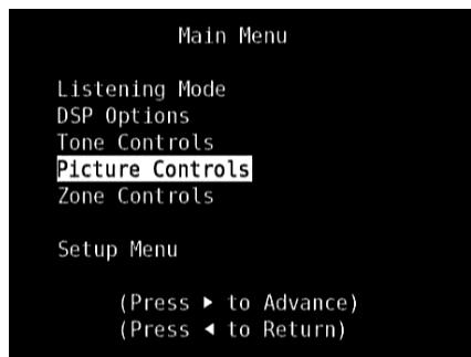
The Main Menu contains the menu options for 'Listening Mode', 'DSP Options', 'Tone Controls', 'Picture Controls', 'Zone Controls' and access to 'Setup Menu'.
To navigate through these Main Menu options and their sub-menu selections, please refer to and follow the directions stated in the sections 'Display the OSD' and 'Navigating the OSD and Making Changes'.
NOTE
The individual configurations set forth at 'Listening Mode', 'DSP Options', 'Tone Controls' and 'Picture Controls' are carried over whenever they are enabled during A/V Preset setting. Please see the section 'AV Presets' for reference.
LISTENING MODE
The T 175 offers distinct listening modes, tailored for different types of recording or program material. With a two-channel (Stereo) source, the following listening modes can be selected:
IMPORTANT NOTICE
The T 175 is an AV Surround Sound Preamplifier and therefore has no speakers. The mention of "Speaker(s)" in this manual refers to the speakers of your external amplifier as interfaced with the T 175.
STEREO
All output is directed to the front left/right channels. Low frequencies are directed to the subwoofer if one is present in the Speaker settings. Select 'Stereo' when you wish to listen to a stereo (or monaural) production, such as music CD or FM broadcast, without surround enhancement. Stereo recordings whether in PCM/digital or analog form and whether surround-encoded or not encoded, are reproduced as recorded. Multi-channel digital recordings (Dolby Digital and DTS) are reproduced in "Stereo Downmix" mode via the front left/right channels only as Lt/Rt (left/right-total) signals.
DIRECT
The analog or digital sources are automatically played in their native formats. All the source's audio channels are reproduced directly. This mode recreates the original sound most faithfully thereby producing outstandingly high quality audio.
PROLOGIC
Two-channel recordings, whether stereo or surround-encoded, are reproduced with Dolby Pro Logic surround processing, yielding output to front left/right, center and discrete left/right surround channels (assuming these are present in the current 'Speaker Configuration'). The surround channel is monophonic, but it is reproduced in both surround speakers.
USING THE T 175 - MAIN MENU
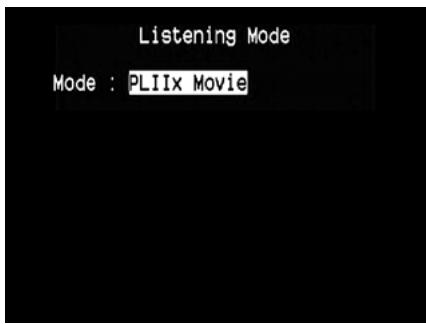
DOLBY PRO LOGIC IIx
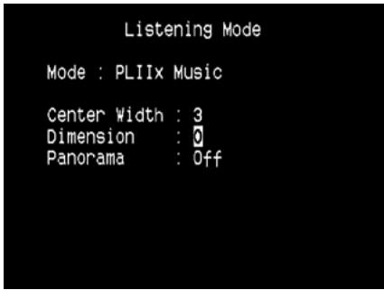
Dolby Pro Logic IIx processes both stereo and 5.1 signals into a 6.1 or 7.1 channel output. At Dolby Pro Logic IIx, you can choose PLIIx Movie or PLIIx Music modes to tailor your listening experience to the source material. Dolby Pro Logic IIx surround processing yields more stable imaging and full bandwidth sound to the rear channels in Movie mode offering sound that is more similar to Dolby Digital decoding. For two channel signals, Pro Logic IIx Music mode also features three additional user controls - Dimension, Center Width, and Panorama. See also section about 'Adjusting Listening Modes' below.
The following chart shows the channels available assuming they are enabled in the 'Speaker Configuration' menu:
| Listening Mode Two-Channel Sources | Active Decoded Output Channels | |
| 6.1 Speaker System | 7.1 Speaker System | |
| Dolby Pro Logic IIx Music Dolby Pro Logic IIx Movie | Front (left & right), Center, Surround (left & right), Back Surround, Subwoofer | Front (left & right), Center, Surround (left & right) and Back Surround (left and right) and subwoofer |
DTS NEO:6
Two-channel recordings, whether stereo or surround-encoded, are reproduced with Neo: 6 surround with output to front left/right, center and discrete left/right surround channels plus subwoofer (assuming these are present in the current 'Speaker Configuration'). The T 175 provides two DTS Neo: 6 variations - NEO:6 Cinema and NEO:6 Music. See also section about 'Adjusting Listening Modes' below.
EARS
Two-channel recordings, whether stereo or surround-encoded, are reproduced with proprietary NAD surround processing with signals output to the front left/right, center and discrete left/right surround channels, plus subwoofer (assuming these are present in the current 'Speaker Configuration!). EARS does not employ the surround back speakers (if any).
EARS extracts the natural ambience present in nearly all well-produced stereo recordings. It does not synthesize any ambience or other sonic elements and thus remains truer to the sound of the original musical performance than most other music-surround options.
Select EARS for listening to stereo music recordings and broadcasts. EARS produces a subtle but highly natural and believable ambience from nearly all "natural-acoustic" stereo recordings. Typically, these include classical, jazz, and folk genres as well as numerous examples from others. Its virtues include realistic, stable "front-stage" sonic imaging and spacious but unexaggerated ambient "virtual acoustics" that remain faithful to the original recording.
ENHANCED STEREO
All recordings are reproduced in stereo via the maximum speaker complement configured in the current 'Speaker Configuration.'Enhanced stereo can be useful for maximum volume from all channels or for multi-speaker background music (cocktail party) listening. For this mode, Front, Center, Surround and Back speakers can be turned ON/OFF as desired.
ANALOG BYPASS
All analog signals remain in the analog domain without analog-to-digital conversions. At Analog Bypass, the DSP circuitry is bypassed but full tone control functions remain. 'Bass management' or Speaker settings are also not in effect as these are DSP functions.
ADJUSTING LISTENING MODES
Several of the T 175's listening modes have one or more selectable variations and adjustable parameters that you can modify to suit you system or personal preferences. At Listening Mode menu, use a combination of ENTER and / keys to navigate and effect desired settings.
NOTE
Listening Mode parameter changes are maintained when you change listening modes. You may also save a modified Listening Mode for easy recall by saving it to a Preset (See 'A/V Presets' below under Setup Menu discussions).
PRO LOGIC IIx
PLIIx MOVIE is optimized for film soundtracks.
PLIIx MUSIC for music recordings
Center Width (0 to 7): Modifies the "hard-centeredness" of the center image, by gradually mixing mono center content to the Front left/right speakers as well. A setting of 0 retains the center-channel-only default while a setting of 7 yields a fully phantom center channel.
Dimension (-7 to +7): Adjusts front-rear emphasis of the surround effect independently from the relative channel levels.
Panorama (On/Off): Adds a "wraparound" effect by extending some stereo content into the surround channels.
NOTE
Pro Logic IIx mode will decode as Pro Logic II mode when the BACK surround speakers are set to "OFF" from "Speaker Configurations" menu. See also section about "Speaker Configurations" under "Speaker Setup" of the Setup Menu.
DTS NEO: 6
NEO: 6 Cinema is optimized for film soundtracks.
NEO: 6 Music for music recordings
Center Gain (0 to 0.5): Adjust for better center image in relation to the surround sound channels.
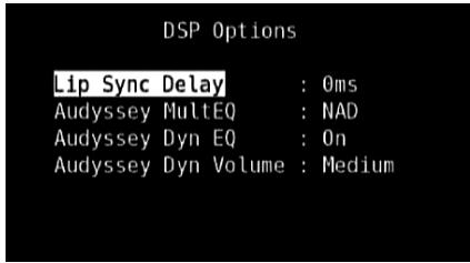
DSP OPTIONS
The following signal processing parameters can be setup under the DSP (Digital Signal Processing) Options menu.
IMPORTANT NOTICE
The T 175 is an AV Surround Sound Preamplifier and therefore has no speakers. The mention of "Speaker(s)" in this manual refers to the speakers of your external amplifier as interfaced with the T 175.
LIP SYNC DELAY
DSP Options has the feature 'Lip Sync Delay' whose function is to match any delay that may occur in the picture relative to the audio.
By varying 'Lip Sync Delay' from 0ms to 120ms, one can delay the audio output in order to synchronize it with the video image.
AUDYSSEY MultEQ
Audyssey MultEQ becomes available among the DSP options only after successfully completing Audyssey Auto Calibration (accessible through the Setup Menu). Refer also to Audyssey Auto Calibration segment of the Speaker Setup under Operation - Using the T 175 - Setup Menu.
Audyssey MultEQ can be set to the following levels
Audyssey: Audyssey developed target curve.
Flat: This setting is appropriate for very small or highly treated rooms in which the listener is seated quite close to the loudspeakers. MultEQ filters are used in the same way as the Audyssey curve, but it does not apply a high frequency roll-off.
NAD: Ideal "in room" response developed by NAD engineers along with Audyssey Engineers.
Off: MultEQ filters are not used or no measurement process at all.
NOTES
- "AUDYSSEY" and a lit green box icon are illuminated at the VFD if NAD, Audyssey or Flat is selected. If "Off" is selected, "AUDYSSEY" and the green box icon will not be illuminated.
- If NAD, Audyssey or Flat is selected and changes are done at the "Tone Controls", "Speaker Configuration", "Speaker Levels" and "Speaker Distance" settings, "AUDYSSEY" and a lit red box icon are illuminated at the VFD. Restore the parameter to its previously calibrated Audyssey setting by adjusting back the altered configuration.
Audyssey MultEQ options can also be directly selected or changed using HTRC 1's AUDYSSEY button with DEVICE SELECTOR set to AMP mode. Toggle AUDYSSEY button to select "Audyssey MultEQ" and then use the
[▲/▼] to select through the Audyssey MultEQ options. Press AUDYSSEY again to save the selected option and at the same time move on to the next menu setting or exit the menu setting altogether.
AUDYSSEY DYN EQ (AUDYSSEY DYNAMIC EQ)
Audyssey Dynamic EQ solves the problem of deteriorating sound quality as volume is decreased by taking into account human perception and room acoustics. By carefully combining information from incoming source levels with actual output sound levels in the room, Odyssey Dynamic EQ delivers unprecedented sound reproduction at all volume levels.
Audyssey Dynamic EQ selects the correct frequency response and surround volume levels moment-by-moment. The resulting bass response, octave-to-octave balance and surround impression remained the same despite changes in volume.
Audyssey Dynamic EQ is designed to work in conjunction with Audyssey MultEQ. Dynamic EQ determines the proper loudness compensation based on the sound pressure level measurements MultEQ provides. Audyssey Dynamic EQ working in tandem with Audyssey MultEQ provides the right listening conditions for every listener at any volume level.
On: Activate Audyssey Dynamic EQ function.
Off: Defeat Audyssey Dynamic EQ function.
NOTE
Audyssey Dynamic EQ and Audyssey Dynamic Volume (see below) can be directly selected or changed using HTRC 1's AUDYSSEY button with DEVICE SELECTOR set to AMP mode. Toggle AUDYSSEY button to select "Dyn EQ" or "Dyn Vol" and then use the [▲/▼] to select through their respective options. Press AUDYSSEY again to save the setting and at the same time move on to the next option or exit the menu setting altogether.
AUDYSSEY DYNAMIC VOLUME
Audyssey Dynamic Volume delivers consistent volume playback levels, anticipating sudden spikes and dips in volume and compensating for them in real time. Audyssey Dynamic Volume monitors the volume of program material moment-by-moment, maintaining the desired listening level for all content while optimizing the dynamic range to preserve the impact.
Audyssey Dynamic Volume includes Audyssey Dynamic EQ, which compensates for deteriorating sound quality as volume is decreased by taking into account human perception and room acoustics. These two technologies enable the full frequency response of the source at its original level to be reproduced at any listening level. Even at lower listening volumes, Dynamic Volume ensures that the richness and dynamics of the response are maintained.
Audyssey Dynamic Volume can be set to the following levels
Light: Provide the least adjustment to the loudest or softest sound level.
Medium: Setting that prevents loud and soft sound from being much louder than their respective average sound levels.
Heavy: Affect volume the most by causing all sound to be of equal loudness.
NOTE
Audyssey Dynamic EQ must be set to "On" to activate Audyssey Dynamic Volume. If Audyssey Dynamic EQ is set "Off", Audyssey Dynamic Volume will also remain "Off".
IMPORTANT NOTICE
If Audyssey Auto Calibration is not set up, the relative balance of your system's loudspeakers has to be manually adjusted (with the aid of a SPL meter) for Audyssey Dynamic Volume and Audyssey Dynamic EQ to be effective. If the speakers are not properly calibrated, the corresponding Audyssey Dynamic Volume and Audyssey Dynamic EQ responses could be distorted. Refer also to the item about "USING SPL METER" in the SPEAKER LEVELS section below.
TONE CONTROLS
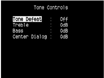
The T 175 has three Tone Control levels – Treble, Bass and Center Dialog. Bass and Treble controls only affect the low bass and high treble leaving the critical midrange frequencies free of coloration. The Center Dialog ('Dialog' in the VFD) control boosts the 'presence' of the midrange region improving intelligibility of speech.
These controls allow one to tweak on-the-fly, the frequency response of the source during playback. The control setting could be adjusted by navigating through the Tone Controls' OSD menu via a combination of ENTER and / keys. The same can be managed directly by pressing the front panel's 'TONE CONTROLS' button and then rotating the Volume knob to select desired setting.
Maximum and minimum values for all three Tone Control levels are +/- 10 dB.
'Tone Defeat' gives one the choice of varying or completely bypassing the tone control section of the T 175. If 'Off' ('Tone Active' in the VFD) is selected, the Tone Control circuits are active.
Select 'On' ('Tone Defeat' in the VFD) to bypass the Tone Controls effectively defeating the effect of the tone control circuits.
NOTE
Tone Control options can be directly selected or changed using HTRC 1's TONE button with DEVICE SELECTOR set to AMP mode. Toggle TONE button to select "Treble", "Bass" or "Dialog" and then use the [▲/▼] to adjust their respective levels. Press TONE again to save the settings and at the same time move on to the next parameter or exit the parameter setting altogether.
PICTURE CONTROLS
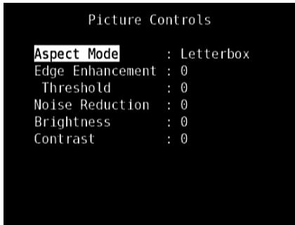
Picture Controls allow video adjustments of the source material or source components to suit one's preference. Set the following levels or settings according to desired level of preference.
ASPECT MODE
The Aspect Mode allows one the choice of adjusting the video output configuration of the T 175.
Letterbox: Original aspect ratio is maintained, preserving the original image's proportions. The unused areas of the screen are left blank.
Zoom: Video display zooms in to the image or scene, cutting off portions that do not fit. Any unused areas of the screen are left blank (i.e., black band).
Stretch: Image or scene is stretched sideways. Any unused areas of the screen are left blank (i.e., black band).
IMPORTANT NOTICE
There is no visible or discernable change in the video display for any of the above three aspect modes if the "Aspect Ratio" of both the source component and the T 175's Video Setup settings (see discussion about "Aspect Ratio" under "Video Setup" menu at "Setup Menu") are exactly the same.
EDGE ENHANCEMENT
Fine details of an image's hard edges are enhanced without adding ringing or halos. Select the level upon which the detected area will be enhanced.
Threshold: Adjusts the sensitivity of the edge detection mechanism.
A lower threshold results in more subtle boundaries of color being identified as edges. A threshold that is too low may result in some small parts of surface textures, film grain or noise being incorrectly identified as being an edge.
NOISE REDUCTION
This setting addresses video distortion like video noise and blocking artifacts.
CONTRAST
Adjust bright areas (white level) of the video display.
BRIGHTNESS
Adjust overall brightness of the video display.
NOTE
Picture controls options can also be directly recalled and adjusted by pressing the numerical "0" key of the HTRC 1 with DEVICE SELECTOR set to AMP. Use the [ / ] keys to select through the settings of a particular option or adjust the levels.
ZONE CONTROLS
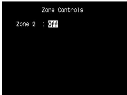
Depending on the settings made at the separate 'Zone Setup' menu under the 'Setup Menu' section discussion, the applicable Zone can be configured and managed via this 'Zone Controls' window.
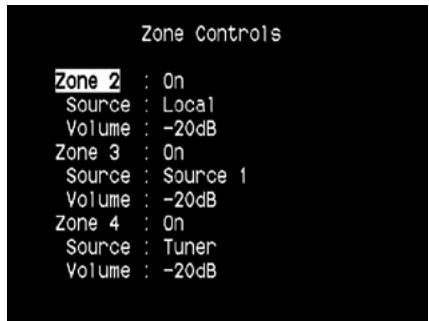
Select 'On' to activate the applicable Zone. When activated, the Source input for the particular Zone can be allocated by selecting through the following inputs - All enabled Sources, Front Input, Media Player, Tuner and Local.
Select 'Local' as your selected Zone's Source input if you wish to enjoy the same source as the main Zone and allow simultaneous listening, but with full separate volume levels.
If a Zone is set to 'Off', it is deactivated or powered off.
'Volume' refers to the adjustable secondary Zone 2 Volume level that can be increased or decreased using the / buttons of the HTRC 1 or front panel's corresponding navigation buttons.
When a Zone is activated, a corresponding Zone number is illuminated at the VFD. Zone 2 is always available to be configured at 'Zone Controls' menu. For Zone 3 and Zone 4 to become available at the 'Zone Controls' window, their corresponding 'Mode' in the 'Zone Setup' menu under the 'Setup Menu' section should be set to 'Zone (Audio Only)'.
NOTE
The ZR 4 remote control will only control Zone 2 applications. Zone 3 and Zone 4 could be configured and managed at the appropriate Zone OSD menu using the front panel navigations buttons as well as the corresponding keys on the HTRC 1 remote control.
USING THE T 175-SETUP MENU
SETUP MENU
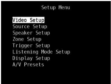
The Setup Menu allows one to customize the operation of the T 175 to the ancillary equipment used in one's specific AV system. Unless your system exactly matches the factory defaults as shown in the accompanying Quick Start Guide, you will need to use the setup menu to configure the inputs of the T 175.
At Setup Menu, the following are configurable – Video Setup, Source Setup, Speaker Setup, Zone Setup, Trigger Setup, Listening Mode Setup, Display Setup and A/V Presets.
To access and navigate through Setup Menu and its sub-menu selections, please refer to and follow the directions stated in the sections 'Display the OSD' and 'Navigating the OSD and Making Changes.'
VIDEO SETUP
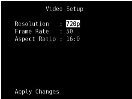
This menu allows you to set the display resolution of the T 175 along with corresponding frame rate and aspect ratio.
Resolution: The T 175 has the excellent ability to upconvert standard definition video contents to high definition video signal. Depending upon your TV/Monitor's resolution capabilities, select the applicable resolution settings - Auto, 480i, 480p, 576i, 576p, 720p, 1080i and 1080p.When "Auto" is selected, the T 175 automatically selects the connected TV/Monitor's highest compatible resolution.
Note that if the display is connected to Composite or S-Video Monitor OUT, the video output resolution must be set to 480i or 576i to view content.
Frame Rate: The frame rate is the number of times per second that a screen image is refreshed. Depending upon your area and video resolution capability of your TV/Monitor, the following "Frame Rate" options are available (Note that frame rate is output resolution dependent; not all frame rate settings are selectable for the various resolution levels).
50Hz: Setting normally for Europe and most of Asia. For resolution settings 576i and 576p, 50Hz is the only available option.
60Hz: Setting normally for North America. For resolution settings 480i and 480p, 60Hz is the only available option.
24Hz: Select to deliver film-like motion characteristics. "24Hz" is selectable only at 1080p resolution setting.
Aspect Ratio: Select a picture size matching the aspect ratio of your TV/Monitor.
4:3: Select "4:3" when a standard 4:3 TV is connected. "4:3" is not selectable when the resolution is set to higher than 480i, 480p, 576i or 576p.
16:9: Select "16:9" when a 16:9 wide TV is connected. "16:9" is the only available option when the resolution is set to 720p, 1080i or 1080p.
After making changes in "Resolution", "Frame Rate" or "Aspect Ratio", scroll down to "Apply Changes" and press [▶] to implement the settings. A new OSD prompt will appear as below
Press the [ ] to apply the new resolution or [] to return to the current resolution. If [ ] is selected, you will be prompted again to another OSD prompt as below
Press [▶] to save the new resolution or [▲] to cancel the change in resolution. If you do not press either [▶] or [▲] and let the timer elapse, the new resolution will not be implemented and the current resolution setting remains.
IMPORTANT NOTE
If you inadvertently selected a resolution setting (like 1080p) that your TV/Monitor does not support, the video display will go blank. To restore video display, press and hold both front panel buttons LISTENING MODE and TONE DEFEAT and then release both buttons - the VFD and OSD will both show "Video Reset". Both the "Picture Controls" and "Video Setup" settings will be restored to their factory defaults after Video Reset.
NOTES
- When using component video output, a standard definition video can be upscaled only up to 1080i.
- When the "Resolution" is set to "Auto", "Frame Rate" and "Aspect Ratio" will not be available as options.
SOURCE SETUP
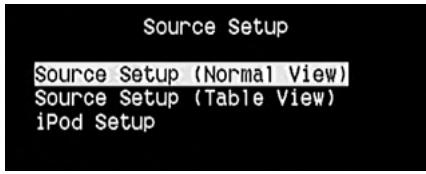
From Setup Menu, pressing will direct you to the Source Setup menu wherein you could adjust allocate or change the settings of the following - Source Setup (Normal View), Source Setup (Table View) and iPod Setup.
SOURCE SETUP (NORMAL VIEW)
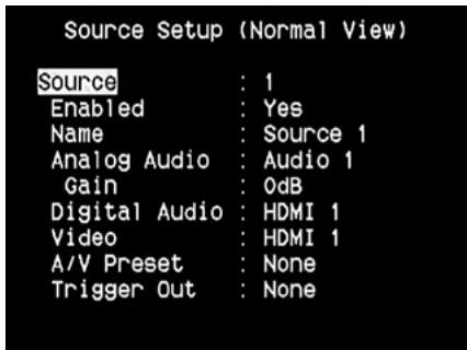
The Source Setup (Normal View) menu makes it possible to set, allocate or change the following settings.
SOURCE
The T 175 is equipped with ten configurable Sources. The settings for each Source are dependent on the configurations set forth in the parameters for that particular Source window.
To change or toggle through the Sources, scroll to 'Source', press▶ button and then ENTER or / to move up or down the Source selections.
NOTE
Source 5 is defaulted to iPod. For Source 5 to be changed and allocated for other inputs, go to 'iPod Setup' menu under the 'Source Setup' menu. At iPod Setup menu, set 'Enabled' to 'No' – you can now assign Source 5 to other inputs or settings as desired.
ENABLED
One can enable/disable a Source via this option. This is particularly useful if only few Sources are used and one directly selects the Source from the front panel, bypassing unused sources.
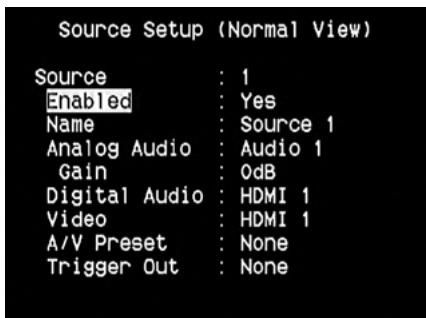
To enable or disable a particular Source, scroll to 'Enabled' and press / keys to select 'Yes' or 'No'.
NAME
A new Name maybe assigned to a Source label. For example, if your DVD player is attached to 'Source 1', it is possible to rename 'Source 1' to 'DVD Player.'
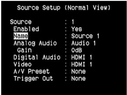
In order to rename the Source label, scroll to 'Name' and press to go the character. Then, press / to pick through the alphanumeric selections.
Press to move to the next character and at the same time save the changes done on the current character. The name can be as long as twelve characters.
The new Name will be shown in the VFD as well as on the OSD.
ANALOG AUDIO
The T 175 has nine analog audio inputs including 7.1 input. These analog inputs - Audio 1, Audio 2, Audio 3, Audio 4, Audio 5, Audio 6, Audio Front, Audio MP and 7.1 Input can be variably assigned to each Source.
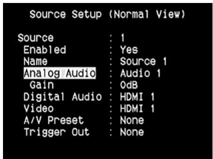
Scroll to 'Analog Audio' and then press and then / to select and assign an analog audio input to the particular Source. There are three choices - Audio, 7.1 Input or Off.
When 'Audio' is chosen, press and then / keys to select and assign the desired audio input - 1 to 6, Front and MP.
Select '7.1 Input' to choose the audio signal fed to '7.1 Channel Input.'If 'Off' is selected, no incoming analog audio signal is selected by the particular Source.
NOTE
An incoming digital signal present at the assigned digital input will always take precedence over the assigned analog audio input, even if both are present. To maintain the analog audio input for the particular Source, select 'Off' at the 'Digital Audio' setting of the same 'Source' menu.
USING THE T 175 - SETUP MENU
GAIN
Gain adjustment allows all sources to play back at the same volume so you don't need to adjust the volume every time a new source is selected. It is generally preferable to reduce the level of the loudest source rather than making louder the softer sources.
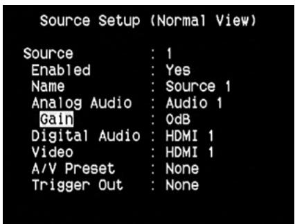
Scroll to 'Gain', press and then / to step through the desired level from -12dB to 12dB.
DIGITAL AUDIO
To take advantage of the T 175's high performance surround and digital audio circuitry, it is advisable that its Digital Audio inputs are selected.
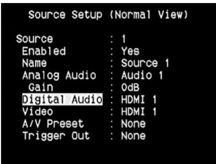
There are three types of Digital Audio input for the T 175. These are HDMI, Optical and Coaxial digital inputs. A fourth option is 'Off' whereby no incoming digital audio signal is selected by the particular Source.
The desired digital audio input for a particular Source can be selected by scrolling to 'Digital Audio', press and then / to step through the desired digital input source. After finalizing the desired type of Digital Audio input, press and then / again to select the specific Digital Audio input.
There are eleven Digital Audio inputs selectable for the T 175. They are the following
HDMI HDMI 1, HDMI 2, HDMI 3, HDMI 4
Optical Optical 1, Optical 2, Optical 3, Optical Front
Coaxial Coaxial 1, Coaxial 2, Coaxial 3
NOTE
An incoming digital signal present at the assigned digital input will always take precedence over the assigned analog audio input, even if both are present. To maintain the analog audio input for the particular Source, select 'Off' at the 'Digital Audio' setting of the same 'Source' menu.
VIDEO
There are four types of video input a particular Source could be assigned. These are HDMI, Component, S-Video and Video inputs. A fifth option is 'Off' wherein the particular Source is prompted not to select any Video input.
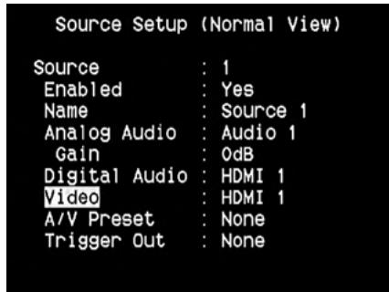
Navigate through the Video input selections by pressing and then / to step through the selections. The following are the assignable Video inputs
HDMI HDMI 1, HDMI 2, HDMI 3, HDMI 4
Component Video Component 1, Component 2, Component 3
S-Video S-Video 1, S-Video 2, S-Video 3, S-Video 4, S-Video 5, S-Video Front
Video Video 1, Video 2, Video 3, Video 4, Video 5, Video Front
VIDEO FORMAT CONVERSION
The T 175 is equipped with a Video Format Converter. This allows for a simplified video connection between the T 175 and your TV Monitor when using multiple video formats such as Composite (CVBS), S-Video, and Component (YUV). This format change is accomplished by encoding the analog video signal into a digital signal using a very high quality digital encoder to maintain the best possible picture quality.
Once in digital format, the video input signal could also be available at the other Monitor output jacks including HDMI MONITOR OUT. Thus, you do not have to necessarily assign the video output of a composite video input signal to MONITOR OUT (Composite video). The composite video input signal can be viewed also at HDMI MONITOR OUT at a resolution setting dependent upon your TV/Monitor's resolution capability. Some TV/Monitors will automatically display the video signal at 480p/576p if they are not capable of displaying 480i/576i.
If your TV/Monitor does not have HDMI input, select the highest quality video format available on your TV/Monitor and utilize this as T 175's preferred Monitor OUT. In most cases, this will be Component Video, but on some older TVs, S-Video maybe the best quality connection.
Refer also to the item above about "VIDEO SETUP".
A/V PRESET
A particular Source can be assigned a stored Preset. The parameters set up in the selected Preset number will be adopted into the particular Source it is assigned (Please refer to the separate section on 'A/V Presets' for further understanding of Preset settings).
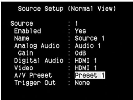
Scrolling to 'A/V Preset' and by pressing and then / keys, a Source could be assigned a Preset number ranging from Preset 1 to 5.
If it is desired not to assign the particular Source a Preset setting, select 'None'.
TRIGGEROUT
The Trigger Out for a particular Source is dependent on the configurations done in a separate menu on Trigger Setup (See 'Trigger Setup'below). If all three available Trigger outputs are assigned to 'Source Setup'in the separate 'Trigger Setup'window, a particular Source can have the following Trigger Out combinations
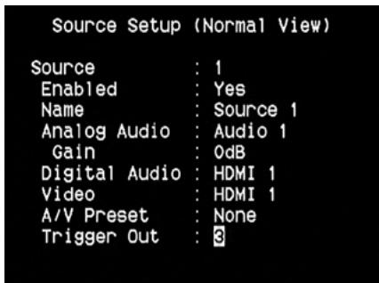
Trigger Out 1 2 1 + 2 3 1 + 3 2 + 3 1 + 2 + 3
These combinations are dependent on the assignment of 'Source Setup' for 'Trigger 1 Out, Trigger 2 Out or Trigger 3 Out' at the Trigger Setup menu. Another option is 'None' whereby the particular Source is not assigned any Trigger Out.
For 'Trigger Out' to become enabled and assignable at 'Source Setup (Normal View)' menu, make sure to carry out or note the following beforehand
- In the separate 'Trigger Setup' menu, assign 'Trigger 1 Out, Trigger 2 Out or Trigger 3 Out' to 'Source Setup'.
- 'Trigger Out' will not appear as an option at the Source Setup (Normal View) menu if at the separate 'Trigger Setup' menu, 'Trigger 1 Out, Trigger 2 Out or Trigger 3 Out' are all assigned to 'Main, Zone 2, Zone 3, Zone 4, or Zone 2 + 3 + 4 '; with not even one 'Trigger Out' port allocated to 'Source Setup'.
SOURCE SETUP (TABLE VIEW)
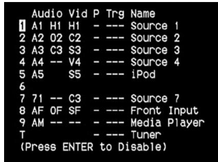
The Source Setup (Table View) reflects the settings made in the Source Setup (Normal View) menu. All the Source settings are summarized and displayed in tabulated form in the Source Setup (Table View).
Navigating through the Source Setup (Table View) via a combination of and then / keys, one will have the benefit of directly changing the settings for 'Audio, Video, Preset, Trigger and Source Name' without going back to the Source Setup (Normal View) menu.
iPod SETUP

The iPod Setup menu allows you to preset the following associated settings when iPod is the selected source:
Enabled: Select 'Yes' to enable iPod as a Source or 'No' to disable it.
Auto Connect: Select 'Yes' to automatically enable and connect the iPod player docked in the linked NAD iPod docking station when Source 5 (the default iPod source allocation in the T 175) is selected. Select 'No' if you do not want for the iPod connection automatically connected.
Menu Timeout: Set the time for the OSD to revert to the 'Now Playing' display when the iPod menu has been left idle (no scrolling or navigation being done) for the specified time out time. For the 'Now Playing' OSD to be shown, there should be a song paused or being played before going to the iPod menu. You can set the 'Menu Timeout' between the range 5s to 60s at 5s increments. If you do not want for the menu to timeout, select 'Off'.
SPEAKER SETUP
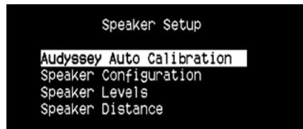
After connecting all ancillary sources and other combinations, the Speaker Setup menu will guide you on how to manage and setup your speakers in order to achieve optimum sound acoustics in your listening environment.
The following are the Speaker Setup Menu sections.
IMPORTANT NOTICE
The T 175 is an AV Surround Sound Preamplifier and therefore has no speakers. The mention of "Speaker(s)" in this manual refers to the speakers of your external amplifier as interfaced with the T 175.
USING THE T 175 - SETUP MENU
AUDYSSEY AUTO CALIBRATION
Audyssey Auto Calibration
Please connect the measurement microphone to the T175.
Position the microphone in the main listening position at ear height.
Start Speaker Detect
It has been shown that many, if not most, surround sound systems are not accurately setup and calibrated. To be done properly, calibration requires special knowledge and instrumentation that the average person probably doesn't possess.
The Audyssey Auto Setup and Calibration featured in T 175 uses a microphone, along with sophisticated digital electronics built into your T 175, to automatically setup and calibrate the T 175 to the exact speakers and speaker placement of your own unique Home Theatre.
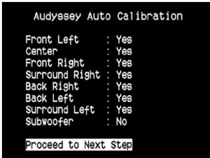
The following measurements are performed:
- Detection: Speaker configuration is detected including number of surround speakers and whether a subwoofer and center channel is connected.
- Size: T 175 crossover is set based on each channel's signal handling capability and the subwoofer crossover is automatically set.
- Level: SPL of each speaker is matched within 1dB at the microphone position.
- Distance : is accurately set to within 1 foot (30 centimeters) of the microphone for each speaker position.
- Polarity: the setup program will detect and notify the user if any speakers are connected improperly. Incorrect polarity can ruin the illusion of realism offered by surround sound.
This is a one-time set up, unless speakers are moved or changed, in which case the calibration should be performed again.
AUDYSSEY MultEQ XT ROOM ACOUSTICS CORRECTION
Sound reflecting from room boundaries can disturb the spatial illusion of surround sound, and can also distort the tonal balance of the system. Professional Acoustical Engineers often add wall treatments and even move walls and relocate speakers to improve system performance, but for the average Home Theatre, this is either too expensive or just not a practical solution.
Audyssey MultEQ XT, using multiple measurements from the actual listening positions, and processing this information using very sophisticated digital signal processing, is able to "precondition" the signal to effectively make the walls disappear. This creates a 'family size' sweet spot where the sound and spatial cues are very accurately reproduced.
MultEQ XT is designed to tame room acoustics without changing the sonic character of your loudspeakers. While it will make the most of whatever loudspeakers you have, it will not make poor speakers sound like good ones!
Connect the Audyssey microphone jack into the front panel's MP/MIC input and the Audyssey Auto Calibration wizard will guide you through a simple step-by-step configuration. Once setup and calibrated, the next greatest improvement in performance is obtained by eliminating the acoustic interference caused by room boundaries interacting with your speakers.
MEASUREMENT IS THE FIRST STEP
The sound at each listening position (up to 8 positions) is calibrated using the same microphone used during the setup phase.
A special test tone is sent to each speaker and the data is memorized by the T 175. The duration of calibration may take some time depending on the number of speakers as well as the number of measuring points. After all positions are measured, the DSP calculates the ideal system response for your particular room and speaker setup.
If some inconsistencies or discrepancies are detected during the Audyssey calibration, the process maybe interrupted or the problem is shown in the particular setup window. A notice screen is correspondingly displayed. After following and undertaking the displayed instructions, re-start the Audyssey calibration again. When the measurements are finalized, Audyssey calculates the ideal system response for your particular room and speaker setup.
NOTE
The test tone emitted during measurement is loud. This maybe bothersome for you and may affect your other household members as well, and even your neighbor.
USING THE T 175 - SETUP MENU
NEXT A TARGET CURVE MUST BE CHOSEN
Because loudspeaker designers assume that their products will be used in typical domestic rooms, they are 'voiced' to work in this environment. It is assumed that the room will add some bass reinforcement and will absorb some treble energy. Thus if we effectively remove the walls with room correction, and set the speakers for flat response, you may find this sounds too bright in the treble and too weak in the bass region.
NAD engineers have done extensive research in this area of room acoustics, and along with Audyssey engineers developed what we believe is the ideal 'in room' response curve. We include this NAD EQ, along with an Audyssey developed EQ as the two best choices. The response curves shown below typify NAD EQ room correction process.
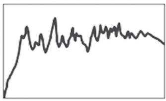
Room Response measured by Audyssey microphone
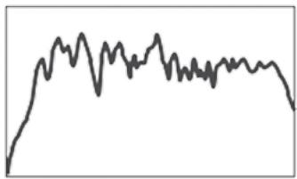
Inverse Correction Filter calculated by NAD T 175
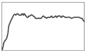
Corrected Room Response
Flat EQ is a third option, but not one that we recommend for listening (it is useful for verifying system performance when using external instrumentation).
Select the Target Curve you find to be most satisfactory by pressing the Audyssey key of the remote. The MultEQ XT corrected response can also be bypassed if you wish.
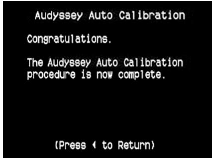
It is recommended that you take full advantage of the T 175's Audyssey Auto Calibration feature for your speaker setup. However, if you desire to setup your speakers manually or if you already had run Audyssey Auto Calibration but would like to make adjustments, the following sections on Speaker Configuration, Speaker Levels and Speaker Distance can also be followed and implemented.
NOTE
During manual setting of your speakers, previously calibrated Audyssey settings could be retrieved by re-adjusting back the altered configurations as highlighted by an asterisk.
USING THE T 175 - SETUP MENU
Every surround-sound system requires "bass-management" to direct low-frequency content from any or all channels to the speakers best able to reproduce it. For this function to operate correctly, it is important that you correctly identify your speakers' capabilities. We use the terms "Small" and "Large" (and "Off") but note that physical size may be irrelevant.
A "Small" speaker is any model, regardless of physical size, that lacks significant deep-bass response, that is, below about 200Hz
- A "Large" speaker is any full-range model; that is, one with deep-bass response
- An "Off" speaker is one that is not present in your system. For example, you might not have any surround-back speakers installed; in that case, you would set the 'Surround' setup item to "Off".
Depending on the relationship between speakers, the possible selections for each speaker are as follows:
| Front L/R | Center | Surround L/R | Back | Subwoofer 1/2 |
| LARGE | LARGE | LARGE | LARGE | ON or OFF |
| SMALL | ||||
| OFF | ||||
| SMALL | LARGE | |||
| SMALL | ||||
| OFF | ||||
| OFF | OFF | |||
| SMALL | LARGE | LARGE | ||
| SMALL | ||||
| OFF | ||||
| SMALL | LARGE | |||
| SMALL | ||||
| OFF | ||||
| OFF | OFF | |||
| OFF | LARGE | LARGE | ||
| SMALL | ||||
| OFF | ||||
| SMALL | LARGE | |||
| SMALL | ||||
| OFF | ||||
| OFF | OFF | |||
| SMALL | SMALL | SMALL | SMALL | ON |
| OFF | ||||
| OFF | OFF | |||
| OFF | SMALL | SMALL | ||
| OFF | ||||
| OFF | OFF |
The Speaker Configuration is "global"; that is, it remains in force with all inputs and in all listening modes. However, speaker settings are part of the T 175's Preset system. Consequently, multiple speaker settings can be stored for easy recall as different types of recordings or listening modes require.
Speaker Configuration can be managed and adjusted by pressing a combination of and then / keys. Set 'Front,"Center,and 'Surround' to "Large, "Small" or "Off" as your subsystem's speakers require.
The 'Back' speakers can either be one or two speakers. Set 'Back' to either 1 or 2 speakers as per availability. Set 'Subwoofer' to "On" or "Off", selecting "On" only if you have a subwoofer connected to the T 175's SUBW1 or SUBW2 output jack.
ENHANCED BASS
When the subwoofer is set to ON and "Front" is set to "Large", Enhanced Bass is also available. Normally, with speakers set to "Large" the subwoofer is not active. The Enhanced Bass option allows full range operation of the speakers with the additional bass contribution of the subwoofer. This feature is particularly useful when one wants to experience maximum bass output. Please note that due to acoustic cancellation effects, the bass response may be uneven when using this setting
You can set Subwoofer to "On" even with "Large" front speakers, in which case bass content from any channels set to "Small" will be routed to both the subwoofer and to the front speakers; LFE-channel signal will pass only to the sub. In most subwoofer-equipped systems, setting front speakers to "Small" is usually the better option.
All the speakers' low frequency content can be directly adjusted within the range 40Hz to 200Hz.
NOTE
The configurations set forth at 'Speaker Setup' are carried over whenever it is enabled during A/V Preset setting. Please see also the section 'AV Presets' for reference.
SPEAKER LEVELS
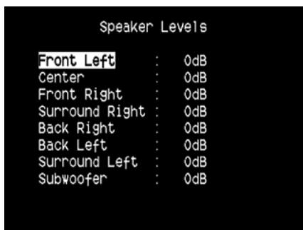
Adjusting the relative balance of your system's loudspeakers ensures that surround-sound recordings, whether music or film, will present the balance of effects, music, and dialog that the artists intended. Additionally, if your system incorporates a subwoofer it establishes a correct relationship between the volume of the subwoofer and the other speakers, and thus of low-frequencies (bass) to other sonic elements.
USING AN SPL METER
It is quite practical to perform the T 175 level setup routines "by ear," and careful work will produce acceptably accurate results. However, the use of an inexpensive sound-pressure level (SPL) meter, such as Radio Shack part number 33-2050, makes this task easier, more accurate and more repeatable. Ownership of such a meter could prove a valuable audio tool.
The SPL meter should be placed at the primary listening position, at approximately the height of the seated listener's head. A tripod is helpful but with a little duct tape almost anything — a pole lamp, music-stand, or ladder-backed chair, for example — can do as well. Just be sure that no large acoustically reflective surfaces obstruct or are near the microphone element.
Orient the meter with its microphone (usually at one end) pointing straight up toward the ceiling (not toward the speakers) and ensure that "C" weighting scale is selected. Set the meter to display 75 dB SPL. On Radio Shack meters, this necessitates either setting the meter to its 80 dB range and taking your readings at the -5 point or selecting the 70 dB range and reading at the +5 point.
SETTING SPEAKER LEVELS AT TEST MODE
While at 'Speaker Levels' menu, press the HTRC 1 remote's 'Test' key activating the T 175's Speaker Levels balancing test signal. You will hear a "surf" sound as you step through your speakers ('test' appears to the right side of the current speaker), beginning with the Front Left. If you do not hear the test signal, check your speaker connections or your 'Speaker Setup' OSD menu settings.
Use the remote's / keys to adjust the loudness of the noise output from the currently playing channel to the required level (it's usually simplest to begin with the Front Left). As you cycle the test signal around the speakers, the OSD will highlight the currently playing channel. The "level offset" reading on the right will change by 1 dB increments; ± 12 dB adjustment is available. Press 'ENTER' to adjust the next speaker.
NOTE
If you are balancing levels "by ear", choose one speaker—usually the center—as a reference and adjust each of the others in turn to "sound as loud" as the reference. Be sure that you remain in the primary listening position while balancing all channels.
To produce the same SPL meter reading (or subjective loudness), use the remote's
/ keys to adjust each speaker.
NOTES
All speakers must be in their final locations before level-setting.
- Your subwoofer (if any) should be set with its integral crossover defeated, or if undefeatable, set to its highest-possible frequency if you are using the T 175's Subwoofer output. Final subwoofer-level adjustment "by-ear," using music and film sound material, is frequently useful.
- Due to the effects of room acoustics, matched-pair speakers (front; surround; back) will not always calibrate to exactly the same level offset readings.
You can exit 'Test' mode at any time by pressing key, bringing you back to 'Speaker Setup' menu. You can also press the 'TEST' key to discontinue the 'Test' mode.
SPEAKER DISTANCE
Your system's speaker distance settings are a subtle but important refinement of your setup. Informing the T 175 of the loudspeaker-to-listener dimensions of each speaker automatically imposes the correct delays, optimizing imaging, intelligibility and surround-sound ambience. Enter your dimensions with precision within about 1 foot (30 cm).
SETTING SPEAKER DISTANCE
While at 'Speaker Distance' menu, use the / keys to individually set Front Left, Center, Front Right, Surround Right, Back Right, Back Left, Surround Left and Subwoofer to the distance measuring from your principal listening position to the front surface of their corresponding loudspeakers. Distance can be set up to 30 feet or 9.1 meters Distance can be displayed as feet or meters selectable at the 'Unit of Measure' item.
ADJUSTING THE VOLUME
In addition to the Volume knob, use the HTRC 1's VOL / to adjust the "master volume" of the T 175 raising or lowering the channels altogether. A momentary keypress will change the master volume by 1 dB increments. If you hold down VOL / , the master-volume change will "run-on" until the key is released. Since recordings vary considerably in overall average level, there is no imperative to listen at any particular master-volume setting. A setting of -20 dB may sound "as loud" from one CD or DVD as -10 dB does from another.
The T 175 will power-up from Standby mode at whatever master volume setting was last used; however, if the prior setting was greater than -20dB , the T 175 will power up at -20dB . This prevents inadvertently beginning a session at excessive volume.
MUTING THE SOUND
Use the HTRC 1's 'Mute' key to silence all channels completely. Muting is always available regardless of the source or listening mode selections.
NOTES
- Changing input or listening-mode selections does not release muting.
- Adjusting the volume level via the HTRC 1 or the front panel volume knob will automatically release the mute function.
USING THE T 175 - SETUP MENU
ADJUSTING CHANNEL LEVELS 'ON THE FLY'
You can make changes to the relative levels of center, surround and subwoofer outputs without having to go into the 'Speaker Levels' menu. This is very convenient in circumstances like increasing (or tone down) a film's dialog level by raising (lowering) the center channel or reducing excessive deep bass (or enhance deep bass) by lowering (raising) the subwoofer level.
Use the HTRC 1's 'SURR,"CENT' and 'SUB' keys for direct-access level adjustment of these channels over a range of ± 6 dB.
The surround back channels (if any) adjust in lockstep with the surround channels.
NOTE
Level settings adjusted 'On the Fly' are added or subtracted to the setup levels established at the T 175 level-calibration routine as invoked by the HTRC 1 'Test' key. However, selecting any Preset will revert the channel levels to those stored in the preset. It will also take T 175 off the levels set via Audyssey Auto Calibration.
ZONE SETUP
The Zone feature allows one to simultaneously experience in different zones of the house multiple sound and applicable video sources from all enabled Sources as well as from Front Input, Media Player and Tuner.
The T 175 has three configurable Zones - Zone 2, Zone 3 and Zone 4. Use a combination of or ENTER and / keys to navigate through the Zone Setup menu parameters.
VOLUME
Zone 2 have Fixed and Variable volume control. When set to 'Variable' and while at the 'Zone Controls' menu OSD, the Zone 2 Volume level can be adjusted using the HTRC 1's / or the corresponding front panel navigation buttons or directly via ZR 4's VOL / .
On the other hand, if Volume is set to 'Fixed', the Zone 2 Volume is set to a preset dB level and thereafter the Zone's volume can be varied via the volume control of the separate amplifier it is fed into.
MODE
Zone 3 and Zone 4 can be configured into two modes – Record Out and Zone (Audio Only). If the selected mode is Record Out, the audio and applicable video signal of the assigned Source are directly sent out to the applicable Audio/Video Output (See Item 11. AUDIO 3 OUT/VIDEO 3 OUT/S-VIDEO 3 OUT, AUDIO 4 OUT/VIDEO 4 OUT/SVIDEO 4 OUT of REAR PANEL discussion.) When Zone 3 or Zone 4 is set to 'Record Out' mode, they will not be available at the 'Zone Controls' section of the Main Menu window.
'Record Out' setting is ideal for making recordings with a VCR or other similar devices. This setting is also used for multi-zone installations using passive 'impedance matching' volume controls. See your NAD dealer for specific information about integrating your T 175 into a multi-room audio distribution system.
Zone 2 and Zone 3 'Volume' will function the same way as that of Zone 2 when 'Mode' is set to 'Zone (Audio Only)'
See discussion also on 'Zone Controls' at the Main Menu.
NOTE
The ZR 4 remote control will only control Zone 2 applications.
TRIGGER SETUP
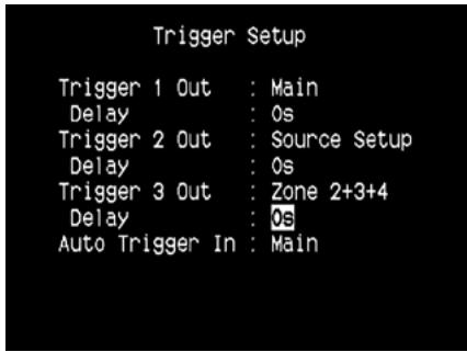
The T 175 features three configurable +12V DC Trigger Output that can be used to activate a component or system it is fed into. A Trigger Input is also available to turn on the applicable link it is associated to. Use a combination of or ENTER and / keys to navigate through the Trigger Setup menu parameters.
TRIGGEROUT
Triggers are low voltage signals used to turn on/off other compliant devices. The T 175's three +12V DC Trigger Outputs (Trigger 1 Out, Trigger 2 Out and Trigger 3 Out) are dependent on which mode they are associated with. There are six choices where +12V DC output can be assigned and these are - Main, Zone 2, Zone 3, Zone 4, Zone 2+3+4 and Source Setup.
Main: +12V DC is available at the assigned Trigger Out when the T 175 is at powered state.
Zone 2, Zone 3, Zone 4, Zone 2 + 3 + 4 : When the applicable Zone is at powered state, +12V DC is available at the assigned Trigger Out.
Source Setup: If Trigger Output is linked to 'Source Setup', +12V DC is available at Trigger Out whenever the particularly assigned Source is selected. Please see also separate discussion about 'Trigger Out' under the Source Setup (Normal) section.
DELAY
The availability of +12V DC at Trigger Out can be regulated. If it is desired that +12V DC is available without delay the moment Trigger Out is linked to its assigned setting, set Delay to 0s. Otherwise, one can select through a delay time of 1s to 15s.
AUTO TRIGGER IN
Auto Trigger IN allows external system controllers to toggle the associated section of the T 175 from 'Standby' to 'On' and vice versa. When the TRIGGER switch at the rear panel is set to AUTO, a +12V DC input at Trigger IN will power ON the section where Trigger IN is assigned,
Main: From standby mode, the T 175 is powered ON when +12V DC is applied at Trigger IN.
Zone 2, Zone 3, Zone 4: Applicable Zone is turned ON whenever +12V DC is present at Trigger IN.
All: Main, Zone 2, Zone 3 and Zone 4 as described above will all be activated given a +12V DC input at Trigger IN.
WARNING
If Auto Trigger IN at Trigger Setup menu is assigned to 'Main' or 'All' and the TRIGGER switch is set to 'AUTO' mode, the Standby button in the front panel as well as the corresponding ON/OFF function keys in the HTRC 1 remote control will be disabled effectively handling this function to an external controller. Switch TRIGGER to 'OFF' to maintain normal power ON/OFF function procedures.
See also 'Item 7. +12 V TRIGGER OUT, TRIGGER IN, TRIGGER AUTO/OFF' of REAR PANEL discussion as well as the 'Trigger Out' discussion under 'Source Setup (Normal View)'
LISTENING MODE SETUP
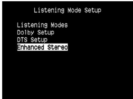
The T 175 has various listening mode options and is mostly configurable. These are provided to reproduce a variety of sound effects depending upon the content of the source to be played. Use a combination of or ENTER and / keys to configure the following settings.
LISTENING MODES
The audio format as detected by the selected Source can be automatically configured and processed through the following options:
DOLBY
Dolby Digital is the multi-channel digital signal format developed in the Dolby laboratories. Discs bearing the Dolby Digital (double-D symbol) logo were recorded with up to 5.1 channels of digital signals, reproducing a much better sound quality, with dynamic and spatial sound sensations that are much better than in the previous Dolby Surround.
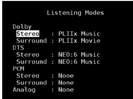
A Dolby Digital audio input can be configured relative to its format as follows
Stereo: If the detected audio is of Dolby stereo format, you can default it to one of the following settings – Pro Logic, PLIIx Movie, PLIIx Music or None.
Surround: If the detected audio is of Dolby Surround format, you can default it to one of the following settings -Surround EX, PLIIx Movie, and PLIIx Music, Stereo Downmix or None.
None: If 'None' is selected, the Dolby Digital signal will be defaulted to the 'Stereo' or 'Surround' settings set forth at the 'PCM' option. See discussion below about 'PCM'.
USING THE T 175 - SETUP MENU
DOLBY DIGITAL PLUS
Dolby Digital Plus is the next-generation audio technology for all high-definition programming and media. It combines the efficiency to meet future broadcast demands with the power and flexibility to realize the full audio potential expected in the upcoming high-definition era.
Dolby Digital Plus delivers multi-channel audio programs of up to 7.1 channels and supports multiple programs in a single encoded bitstream with the maximum bit rate potential of up to 6 Mbps and the maximum bit rate performance of up to 3 Mbps on HD DVD and 1.7 Mbps on Blu-ray Disc. It outputs Dolby Digital bitstreams for playback on existing Dolby Digital systems. Dolby Digital Plus can accurately reproduce the sound originally intended by directors and producers.
It also features multi-channel sound with discrete channel output, interactive mixing and streaming capability in advanced systems. Supported by High-Definition Media Interface (HDMI), a single-cable digital connection is possible for high-definition audio and video.
DOLBY TrueHD
Dolby TrueHD is a lossless encoding technology developed for high-definition optical discs in the upcoming era. Dolby TrueHD delivers tantalizing sound that is bit-for-bit identical to the studio master, unlocking the true high-definition entertainment experience on high-definition optical discs in the next generation. When coupled with high-definition video, Dolby TrueHD offers an unprecedented home theater experience with stunning sound and high-definition picture.
It supports bit rates of up to 18 Mbps and records up to 8 full-range channels individually with 24-bit/96 kHz audio. It also features extensive metadata including dialogue normalization and dynamic range control. Supported by High-Definition Media Interface (HDMI), a single-cable digital connection is possible for high-definition audio and video. HD DVD and Blu-ray Disc standards currently limit their maximum number of audio channels to eight, whereas Dolby Digital Plus and Dolby TrueHD support more than eight audio channels. Note that the T 175 only supports 7.1 channel.
DOLBY DIGITAL EX
Using a Matrix decoder, this method creates the back channel (sometimes also called the "surround center") by means of signals on the left and right surround channels recorded in Dolby Digital 5.1, reproduction being provided in Surround 6.1. This method should be selected with sources bearing the "Dolby Digital (double-D symbol)-EX" symbol, recorded in Dolby Digital Surround EX.
With this additional channel you will experience improved dynamics and a better sensation of movement within the sound field. If media sources recorded in Dolby Digital EX are decoded with a Digital EX decoder, the format is detected automatically, and the Dolby Digital EX mode is selected. However, some media sources recorded in Dolby Digital EX can be detected as simple Dolby Digital media sources. In this case Dolby Digital EX should be selected manually.
NOTE
Please refer to the section 'Listening Mode' at the Main Menu discussions for a description of Pro Logic, PLIIx Movie, PLIIx Music and Stereo Downmix modes.
DTS
The Digital Theater System Digital Surround (simply called DTS) is a multi-channel digital signal format that can process higher data rates than with Dolby Digital. Although both Dolby Digital and DTS are 5.1 channel media formats, discs bearing the "DTS" symbol are thought to provide better sound quality due to the lower audio compression required. It also offers a broader dynamic, producing magnificent sound quality.
A DTS audio input can be configured relative to its format as follows
Stereo: If the detected audio is of DTS format, you can default it to one of the following settings – NEO:6 Cinema, NEO:6 Music or None.
Surround: If the detected audio is of DTS Surround format, you can default it to one of the following settings - NEO:6 Cinema, NEO:6 Music, Stereo Downmix or None.
None: If 'None' is selected, the DTS signal will be defaulted to the 'Stereo' or 'Surround' settings set forth at the 'PCM' option. See discussion below about 'PCM'.
NOTE
Please refer to the section 'Listening Mode' at the Main Menu discussions for a description of Stereo Downmix and DTS Neo:6 surround modes.
PCM
PCM (Pulse Code Modulation) is the digital representation of a standard audio signal converted with little or no compression. If 'None' is selected for any of the Dolby or DTS settings, this 'PCM' section will default the audio signal as follows
Stereo: The detected stereo audio format will be configured into one of the following options - Pro Logic, PLIIx Movie, PLIIx Music, NEO:6 Cinema, NEO:6 Music EARS, Enhanced Stereo or None.
Surround: The detected surround audio format will be configured into one of the following options -PLIIx Movie, PLIIx Music, NEO:6 Music, NEO:6 Cinema, Stereo Downmix or None.
ANALOG
If the audio input is an analog signal, the following are the surround modes the input can be defaulted - Pro Logic, PLIIx Movie, PLIIx Music, NEO: 6 Cinema, NEO: 6 Music, EARS, Enhanced Stereo, Analog Bypass and None.
NOTE
All these Listening Modes for 'Dolby Digital', DTS' 'PCM and 'Analog' can be directly changed by pressing the 'Listening Mode' button on the front panel or through the 'Listening Mode' option at the Main Menu window. The chosen audio format will be reflected back to the appropriate setting at the 'Listening Mode Setup.'
DOLBY SETUP
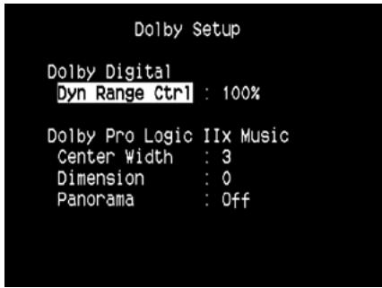
Under this menu, the Dolby Digital's Dynamic Range Control can be adjusted as well as the settings for Dolby Digital Pro Logic IIx Music.
Dyn Range Ctrl: You can select the effective dynamic range (subjective range from soft to loud) for playback of Dolby Digital soundtracks. For fully cinematic effect, always select 100% , the default. Settings of 75% , 50% , and 25% progressively reduce dynamic range, making soft sounds comparatively louder while limiting the peak loudness of loud ones.
The 25% setting will yield the least dynamic range and is best for late-night sessions or other times when you wish to retain maximum dialog intelligibility while minimizing overall volume levels.
Dolby Pro Logic IIx Music: Please refer to the same description of 'PLIIx Music' under the 'ADJUSTING LISTENING MODES' segment of the 'OPERATION - USING THE T 175 - MAIN MENU'.
DTS SETUP
Under this menu, the Dynamic Range Control of DTS Digital Surround can be adjusted as well as the settings for DTS Neo: 6 Music.
Dyn Range Ctrl : This is the same configurable Dynamic Range Control feature as described above at Dolby Setup, the only difference being the soundtrack is now in DTS format.
DTS Neo: 6 Music : Please refer to the same description of 'NEO 6: Music' under the 'ADJUSTING LISTENING MODES' segment of the 'OPERATION - USING THE T 175 - MAIN MENU'.
DTS SURROUND MODES
The following are further descriptions about the DTS surround modes.
DTS-HD MASTER AUDIO
DTS-HD Master Audio is a technology that delivers master audio sources recorded in a professional studio to listeners without any loss of data, preserving audio quality. DTS-HD Master Audio adopts variable data transfer rates, facilitating data transfer to the maximum rate of 24.5 Mbps in the Blu-ray disc format, 18.0 Mbps in the HD-DVD format, which by far exceeds that of a standard DVD. These high data transfer rates enable lossless transmission of 96 kHz/24-bit 7.1-channel audio sources without deteriorating the quality of the original sound. DTS-HD Master Audio is an irreplaceable technology that can reproduce sound faithfully as intended by the creator of music or movies.
DTS - ES EXTENDED SURROUND ^TM (DTS ES)
This is a new multi-channel digital format which greatly improves the 360^ spatial sensation of the Surround impression thanks to the greater space expansion of the surround signals, providing high compatibility with the conventional DTS format.
In addition to the 5.1 channels, the expanded DTS-ES Surround also offers the back surround (also sometimes called the "surround centre") in reproduction, providing a total of 6.1 channels. The expanded DTS-ES Surround includes two formats, with two different methods of surround signal recording, as follows:
DTS-ESTM DISCRETE 6.1
Since the signals of the 6.1 Surround channels (including the back channel) are completely independent, it is possible to achieve the sensation that the acoustic image is moving about freely among the background sounds, 360 degrees surrounding the listener.
Although maximum quality is achieved with sound tracks recorded using this system and reproduced using the DTS-ES decoder, when played with a conventional DTS decoder, the back surround channel is automatically downmixed in the surround right and surround left channels of the surround system, in such a way that none of the signal components are lost.
USING THE T 175 - SETUP MENU
DTS-ESTM MATRIX 6.1
In this format, the additional signals of the back channel receive a matrix encoding and are inputted into the right and left surround channels. During reproduction they are decoded to the right, left and back surround channels.
Since this bit-stream format is 100% compatible with conventional DTS signals, the DTS-ES Matrix 6.1 format effect can also be achieved from sources with DTS-ES 5.1 signals.
Naturally, it is also possible to reproduce from a DTS 5.1 channel decoder, signals recorded in DTS-ES 6.1.
When a DTS-ES decoder processes a discrete DTS-ES 6.1 or in Matrix 6.1, these formats are automatically detected and the Optimum Surround mode is selected. However, some DTS-ES Matrix 6.1 sources may be detected as DTS. In this case the DTS-ES Matrix mode should be selected manually in order to reproduce them.
DTS NEO: 6^TM SURROUND
This mode applies the conventional 2-channel signals such as digital PCM or analog stereo signals to the high precision digital matrix decoder used for DTS-ES Matrix 6.1 to achieve 6.1-channel surround playback. DTS Neo: 6 surround includes two modes for selecting the optimum decoding of the signal sources:
DTS NEO: 6 CINEMA : This method is ideal for the reproduction of movies. The decoding takes place by emphasizing the separation in order to achieve the same atmosphere with 2-channel, as with 6.1-channel sources.
DTS NEO: 6 MUSIC: Mainly recommended for music reproduction.
The right and left front channels do not pass through the decoder and are reproduced directly so there is no loss in sound quality, and the effects of the right surround, left surround, central and back surround channels add a natural sensation of expansion of the sound field.
ENHANCED STEREO
Please refer to the same description of 'ENHANCED STEREO' under the 'LISTENING MODES' segment of the 'OPERATION - USING THE T 175 - MAIN MENU'.
DISPLAY SETUP
The Vacuum Fluorescent Display (VFD) and On-Screen Display (OSD) can be shown in various ways by navigating through the parameters at the 'Display Setup' menu. Use a combination of or ENTER and / keys to step through the 'Display Setup' menu items.
NOTE
The configurations set forth at 'Display Setup' are carried over whenever it is enabled during A/V Preset setting. Please see also the section below about 'AV Presets.'
Display: Select 'On' to display all applicable data or characters at the VFD. Nothing will be shown at VFD if 'Temp' is selected. At 'Temp' setting however, whenever any of the front panel controls or their corresponding keys in the remote control is activated, the appropriate VFD characters will be shown temporarily and then fade away. Note that if any of the Zones are at powered state, they will be continually shown at VFD even at 'Temp' setting.
Dimmer : If it is desired to reduce the brightness of the VFD, set Dimmer to 'Dim'. Otherwise, select 'Bright' to return to normal VFD brightness.
Line 1, Line 2: The VFD shows two main lines of data or characters. Line 2 is the line of data or characters located at the lower bottom of the VFD while directly above it is Line 1. For both lines, one can select which display could be shown by choosing through the following
Main Source : Shows the active Source.
Volume : Current Volume level is shown.
Listening Mode: Selected Listening Mode is shown.
Audio Src Format : Shows the active Source's detected audio format.
Audio Codec: Displays the detected audio stream format like Analog, PCM Surround, Dolby TrueHD, DTS-HD Master Audio and other formats.
Video Mode: Show the video resolution of the active input source. Details shown include the video resolution with frame rate. For a better understanding of these video details, consult with your NAD Audio Specialist or your distributor's technical department.
Zone 2-Zone 3-Zone 4 Source: The assigned Source for the applicable Zone is shown.
Off: Select 'Off' if it is desired not to show any data at the applicable Line.
Temp Line : Choose between Line 1 and Line 2 as the desired line where VFD will be temporarily shown if 'Temp' is selected at 'Display' option as described above.
ON-SCREEN DISPLAY (OSD)
Temp Disp: This applies to the OSD that is temporarily shown at video out whenever any of the front panel controls or their corresponding keys in the remote control is activated. Set to 'On' if it is desired to show the applicable OSD at the monitor/TV; otherwise, select 'Off'.
A/V PRESETS
The T 175's simple but powerfully flexible system of 'Presents' allows you to customize virtually every aspect of your audio-video playback, and recall them with a single key-press. The parameters 'Listening Mode', 'DSP Options', 'Tone Controls' and 'Picture Controls' accessible via the 'Main Menu' together with 'Speaker Setup and Display Setup' configurable through 'Setup Menu' are stored together as a Single Preset.
You might create one Preset optimized for pop music and another for classical. One more Preset can be set up to recall each family member's favorite setting or one for fully cinematic home-theater playback and yet another one for late-night movies, with each Preset fine-tuned to a particular scenario or preference.
CREATING PRESETS
Creating a Preset consists simply of storing a complete set of the parameters set forth in the 'Listening Mode","DSP Options","Tone Controls" and 'Picture Controls' accessible via the 'Main Menu' together with 'Speaker Setup and Display Setup' configurable through 'Setup Menu.'
Scroll to A/V Presets' using the / keys to save a collection of said parameter settings to a Preset. Select a Preset number and by a combination of pressing the / keys, you can selectively include in the particular Preset any of the above-mentioned parameter settings by choosing Yes' If you decide not to include in the particular Preset a certain parameter setting, select No'.
Now in order to save the settings chosen for the particular Preset number, scroll down to 'Save Current Setup to Preset' and press the key. If you chose to load instead the default settings, scroll down to 'Load Defaults to Preset' and press the key to restore the default settings.
In addition to the parameter settings, the Preset label itself can be assigned a new name. This new Name will be shown in the VFD as well as on the OSD.
To rename the Preset label, scroll to 'Name' and press to go the character. Then, press / to pick and select through the alphanumeric selections. Press / to move to the next character or back to the previous character and at the same time save the changes done on the current character.
NOTE
The selected Preset remains in force until you select a different Preset.
SAMPLE PROCEDURE FOR SETTING UP A/V PRESETS
1 Setup first your preferred settings for the following options (access them through their respective menu page).
Listening Mode: Stereo
DSP Options: 5ms
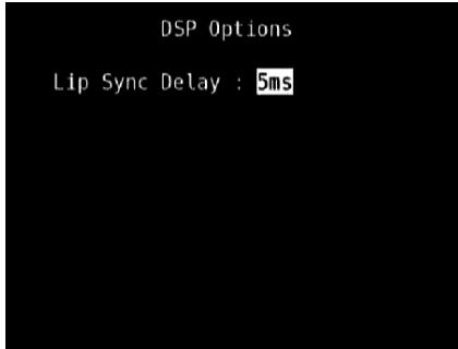
Tone Controls: Tone Defeat: On
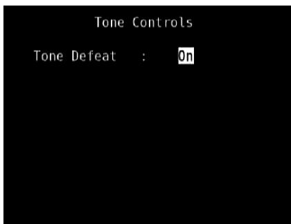
Display Setup: Set "Line 2" to "Listening Mode"
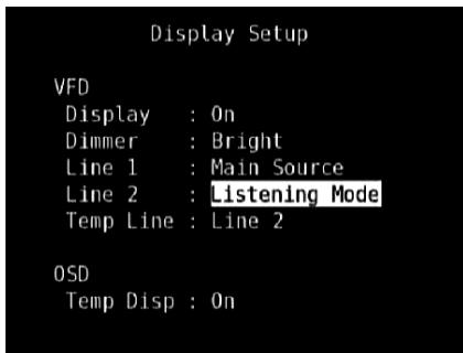
USING THE T 175 - SETUP MENU
Picture Controls: Aspect Mode - Letterbox
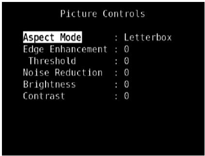
Speaker Setup: from the Speaker Setup menu, go to "Speaker Configuration" sub-menu and change "Subwoofer" from "On" to "Off": "Front" becomes "Large"
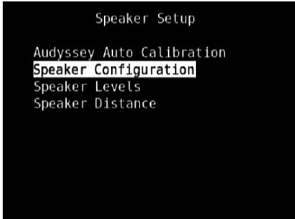
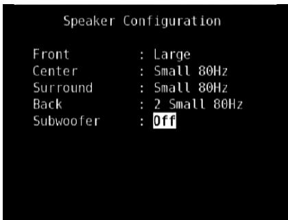
2 With the above settings, scroll to "A/V Presets" from the SETUP MENU page. Use [▶] to access "A/V Presets" menu.
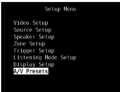
3 At "A/V Presets" page, set "Preset: 1" to the following conditions - use [/] to select "Yes" or "No" and press [ENTER] to confirm selection and move on to the next setting
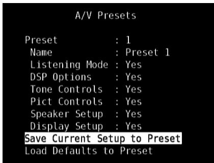
While at "Save Current Setup to Preset" menu line, use [▶] to save the above settings to Preset 1. Below OSD will be shown, affirming that the above settings are now saved to "Preset 1".
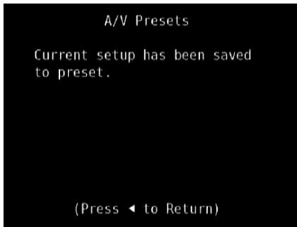
When you recall "Preset 1" using the remote control (for HTRC 1, "A/V PSET" + "1"), the above preset values allocated at "Preset 1" (preset settings as shown in the OSD captures at Step 1) will be recalled and effected at the current source.
4 Now, repeat again Step 1 above but this time with the following settings
Listening Mode: PLlIx Music
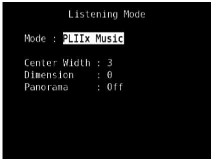
DSP Options: 0ms
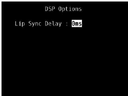
Tone Controls: Tone Defeat: Off
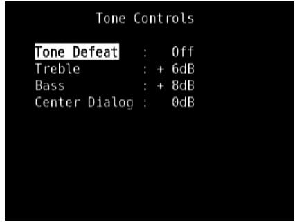
Display Setup: Set "Line 2" to "Volume"
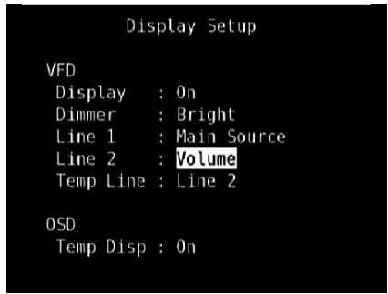
Picture Controls: Aspect Mode - Stretch
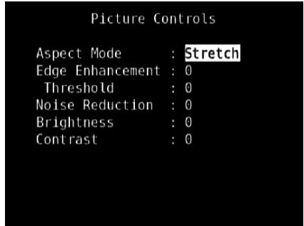
5 With the above settings, scroll to "A/V Presets" from the SETUP MENU page. Use [▶] to access "A/V Presets" menu.
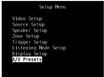
6 At "A/V Presets" page, set "Preset: 2" to the following conditions - use [/] to select "Yes" or "No" and press [ENTER] to confirm selection and move to the next setting
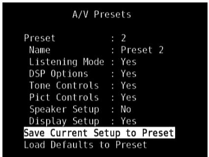
While at "Save Current Setup to Preset" menu line, use [▶] to save the settings above to "Preset 2". When you recall "Preset 2" using the remote control (for HTRC 1, "A/V PSET" + "2"), the above preset values allocated at "Preset 2" (preset settings as shown in the OSD captures at Step 4) will be recalled and effected at the current source.
Note that "Speaker Setup" is set to "No". At this condition, there will be no "Speaker Setup" values that will be effected at "Preset 2". The "Speaker Setup" settings that will be applied at "Preset 2" will be the last or current "Speaker Setup" settings which in this sample are the same "Speaker Setup" settings shown above in Step 1.
7 You can setup up to 5 Presets. These same Presets can also be associated/defaulted to each Source in the "Source Setup (Normal View)" window as below
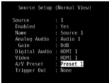
In the above example, "Preset 1" settings are allocated for Source 1. Whenever Source 1 is accessed, the "Preset 1" settings will be applied to Source 1. You can still manually override the assigned Preset allocation in a specific Source with another Preset setting/number by way of pressing the appropriate remote control buttons.
RECALLING PRESETS
You may recall a Preset at any time using the HTRC 1 remote control. Press the HTRC 1's A/V PSET key and then the numeric key 1-5 corresponding to the desired preset number. The newly recalled Preset will then manifest or replace the previous Preset (if any).
USING THE T 175 - AM/FM/DB/iPod
LISTENING TO AM/FM RADIO
The T 175's internal AM/FM tuner offers very high quality sound from radio broadcasts. The reception and sound quality will always be dependent to a degree however on the type of antenna(s) used as well as proximity to the broadcast origin, geography and weather conditions.
ABOUT ANTENNAS
The supplied ribbon-wire FM antenna can be connected to the rear-panel FM-antenna input using the included 'balun'adapter and should be fully extended to form a "T". This folded-dipole antenna will usually work best when oriented vertically, with the arms of its "T"fully outstretched and arranged perpendicular to the origin of the desired broadcast. There are no 'rules' however, and experimenting freely with antenna placement and orientation may yield the clearest sound and lowest background noise.
In areas of poor FM reception, an exterior FM antenna can improve performance dramatically. If radio listening is important to you, consider consulting an antenna installation professional to optimize your system.
The supplied AM 'loop' antenna will usually provide adequate reception. However, an exterior AM antenna can be used to improve reception. Consult an antenna professional for more information.
IMPORTANT NOTICE
Unless otherwise specifically stated, navigating or accessing AM/FM functions can be undertaken by using either the HTRC 1 remote control or the front panel buttons. If the control button or icon button being referred to is available on the HTRC 1 remote control and front panel, then the reference to said button is applicable to both the HTRC 1 remote control and front panel. The same condition applies to their equivalent buttons.
NOTE
When using the HTRC 1 to carry out AM/FM commands, ensure that the DEVICE SELECTOR is set to "TUNER".
ASSEMBLING THE LOOP ANTENNA
1 Rotate the outer frame of the antenna.
2 Insert the bottom edge of the outer frame into the groove on the stand.
3 Extend the antenna cord.
SELECTING A TUNER BAND
Press the [AM/FM/DB] button on the front panel or the numeric +10^ button of the HTRC 1 while at AMP or TUNER device selector page. Each subsequent press of either button will toggle you through AM, FM and XM (or DAB) band. Stop (release button) at your desired tuner band.
TUNING STATIONS
1 Press TUNE / on the front panel momentarily to step up or down between AM or FM frequencies.
2 Press and hold TUNE or TUNE for more than 2 seconds to search up or down - the T 175's tuner will stop at the next sufficiently strong signal it encounters. Pressing the TUNE / during the search process will stop the search.
3 After first pressing 'TUNER' (yellow lettering) at the Device Selector page of HTRC 1 to set the remote to control Tuner functions, press TUNE or TUNE (yellow lettering) on the HTRC 1 - toggle in to perform slow manual search, press and hold to automatically search.
DIRECT TUNING
If you know your desired station's frequency allocation, you can tune directly to the station.
1 Toggle [ENTER] button to switch between "Preset" and "Tune" mode (see the lower line of the VFD). Select "Tune" mode.
2 Using the numeric keys of the remote control, key-in the frequency allocation of the station. For example, to enter 104.50MHz, press 1, 0, 4, 5 and 0 or press 1, 0, 4, 5 and then [ENTER].
SETTING RADIO PRESETS
The T 175 can store a mix of your 40 favorite AM, FM and XM (or DAB) radio stations for immediate recall.
1 To store a radio preset, first tune the desired frequency (see above), then press the front panel 'MEMORY' key.
2 The VFD will show the next available preset number (Preset __ Free). If there are no more vacant Preset number, you can overwrite an existing Preset number by pressing the / buttons on the HTRC 1 (or corresponding front panel navigation buttons) to select the Preset number you want to overwrite.
3 Then, press the 'MEMORY' key once again to save the station to the particular Preset number and displaying 'P_-'(the two blank spaces will correspond to the preset number that could be from '01' to the maximum of '40') on the VFD.
4 Press PRESET / on the front panel to step up or down between presets. Press and hold PRESET / to "scroll" continuously up or down. The HTRC 1 remote's PRESET / keys work similarly.
NOTE
The T 175's Radio Presets are distinct from its 'global' Presets that can be used to manage listening and setup modes and levels. See 'A/V Presets' above.
DIRECT RECALL OF A PRESET
You can directly recall a desired Preset number.
1 Toggle [ENTER] button to switch between "Preset" and "Tune" mode (see the lower line of the VFD). Select "Preset" mode.
2 Using the numeric keys of the remote control, key-in directly your desired Preset number.
DELETE A PRESET
1 Select the Preset number to be deleted.
2 Press and hold [MEMORY] button and then press and release [INFO] button - current stored preset setting will be erased. The Radio Preset can only be deleted using the front panel buttons.
CHOOSING THE TUNER MODE
The front-panel 'TUNER MODE' key is a dual-purpose control. In the normal position, FM Mute FM Stereo icons on the VFD are illuminated, only the stations with a strong signal can be listened to, and the noise between stations is muted.
Pressing the 'TUNER MODE' button again (FM Mute FM Stereo icons on the VFD are extinguished) allows distant and potentially noisy stations to be received. Noise is reduced if the FM station signal level is less than the FM Stereo threshold (since mono FM is inherently less noise-prone) though at the sacrifice of the stereo effect.
NOTE
One can store the same channel in two preset locations - one with TUNER MODE On and another with TUNER MODE Off.
ABOUT USER NAMES
You can assign an eight character "UserID" to each radio preset, which will show in the front-panel readout whenever that preset is recalled.
ENTERING USER NAMES
To name a radio preset "NEWS," follow the procedure as below (The buttons mentioned apply to the front panel's buttons. The applicable HTRC 1 keys also execute the same functions as described).
1 Recall the desired radio preset.
2 Then, press the 'MEMORY' button once and then within five (5) seconds, press the 'NFO' button - the readout shows a blinking box.
3 Use the 'PRESET / ' buttons to select the first character of the name ("N" from the alphabetical list).
4 Press 'TUNE▶' button to select the character and correspondingly move forward to the next position. (Press TUNE to go back to the previous character). Repeat this process for each character in sequence.
5 Press the MEMORY key again to store the User Name and exit the text-entry mode.
ABOUTRDS
The Radio Data System (RDS) permits compatible FM tuners or receivers to display text determined by the broadcaster. The T 175 supports two RDS modes, station-name (PS mode) and radio-text (RT mode). However, not every FM station incorporates RDS in its broadcast signal. In most areas you will find from one to several RDS-enabled stations, but it is by no means impossible that your favorite stations will not be broadcasting RDS data.
VIEW RDS TEXT
When an RDS-enabled FM broadcast is tuned, after a brief delay the "RDS" symbol will illuminate in the T 175's front-panel readout and the readout's character section will show its station-name (PS) text: "ROCK101,"for example.
Press the front-panel INFO key to toggle the readout between this and the station's radio-text (RT) readout, if any, which might scroll song- or artistname, or any other text of the station's choosing.
LISTENING TO XM RADIO
The T 175 is "XM Ready" which means that with the addition of separately sold XM Mini-Tuner CPC-9000 and XM Mini-Tuner Home Dock, it has everything you need to listen to live XM. Everything else is built right in. Just subscribe to the XM service and your T 175 will be ready to receive XM content.
NOTES
- When using the HTRC 1 to carry out XM commands, ensure that the DEVICE SELECTOR is set to "TUNER".
- In XM mode and with DEVICE SELECTOR set to "TUNER", HTRC 1's [FM MUTE] button has the same function as that of the front panel's [TUNER MODE] button.
- Check with your NAD audio specialist for other versions of XM Mini-Tuner compatible with T 175.
IMPORTANT NOTICE
Unless otherwise specifically stated, navigating or accessing XM functions can be undertaken by using either the HTRC 1 remote control or the front panel buttons. If the control button or icon button being referred to is available on the HTRC 1 remote control and front panel, then the reference to said button is applicable to both the HTRC 1 remote control and front panel. The same condition applies to their equivalent buttons.
CONNECTING THE XM ANTENNA
1 Plug the end of the XM antenna into the corresponding XM antenna port on the rear panel of the T 175.
2 Press and hold "TUNER MODE" button on the front panel to check the current XM channel's signal strength as shown in the VFD and OSD. Press "TUNER MODE" again to exit signal strength check.
Refer also to your XM radio's guide on how to install the XM antenna for optimum signal reception.
TUNING STATIONS
There are three ways to tune to the XM channel you wish to listen. Make sure to set your HTRC 1's Device Selector to "TUNER" prior to undertaking the following tuning options. The / / buttons refer to the corresponding keys on the HTRC 1. The same keys correspond to the front panel navigation buttons "PRESET I / PRESET / TUNE / TUNE
1 Manual Tuning: Toggle the / buttons to step up or down each available XM channel. Press and hold / for faster scanning of XM channels. The HTRC 1 keys "TUNE / TUNE will likewise execute these same functions.
2 Direct Channel Call: Using the numeric keystads of the HTRC 1, key-in directly the desired available channel number and it will be automatically tuned.
3 Category: Toggle "TUNER MODE" until "CATXM" and a corresponding category is displayed on the VFD. "CATXM" stands for the categories channels are grouped into - i.e., Country, Rock, Jazz & Blues, etc. Toggle / buttons to step up or down the available categories.
After selecting the desired category, use the same steps as that of XM Manual Tuning. Tuning will only be limited to within the selected category. Toggle the / buttons to choose another category and then tune again.
USING THE T 175 - AM/FM/DB/iPod
VIEW XM INFORMATION
Toggle 'INFO' button to display the XM information of the selected channel such as the artist name, song title, category or any other text as supplied for the channel.
PRESETS
The procedure for storing XM channels is the same method as stated in the section "Setting Radio Presets" under "Listening to Radio."
For immediate recall of stored XM presets, toggle "TUNER MODE" button until "P_(the two blank spaces corresponding to the preset number) is shown in VFD. Press the front panel's "PRESET|PRESET> button or HTRC 1's / keys to step up or down the stored presets that can be a combination of AM, FM and XM channels.
LISTENING TO DAB RADIO
Until now, analogue radio signals such as FM or AM have been subject to numerous kinds of interference on their way from the transmitter to your radio. These problems were caused by mountains, high-rise buildings and weather conditions. With Digital Audio Broadcast (DAB), you can now receive CD-like quality radio programs without any annoying interference and signal distortion. DAB broadcasts use digital signals rather than traditional analogue transmissions, thus providing clear high quality reception. You get far more robust reception and virtually hiss or crackle free sound with DAB as long as you are within a good coverage area.
With DAB, the listener can scroll through a list of available stations - then instantly tune to the station of his choice. There is no need either to remember channel frequencies. All broadcasts are selected by simply selecting the service name.
The T 175 makes it possible for you to enjoy listening to DAB broadcasts. The T 175 has a Digital Audio Broadcast (DAB) module socket on the rear panel for adding a separately sold and NAD-specified outboard DAB module – the NAD DAB Adaptor DB 1. All the control software for this format is included; just plug-in the module and start enjoying the CD-like quality sound and expansive content selection available with DAB.
IMPORTANT NOTICE
Unless otherwise specifically stated, navigating or accessing DAB functions can be undertaken by using either the HTRC 1 remote control or the front panel buttons. If the control button or icon button being referred to is available on the HTRC 1 remote control and front panel, then the reference to said button is applicable to both the HTRC 1 remote control and front panel. The same condition applies to their equivalent buttons.
NOTES
- When using the HTRC 1 remote control to carry out DAB commands, ensure that the DEVICE SELECTOR is set to "TUNER".
- HTRC 1'S [FM MUTE], [ENTER] and / are the equivalent remote control keys for the front panel buttons [TUNER MODE], [ENTER] and [TUNE / ].
CONNECTING THE DAB MODULE
Plug-in the other end of the DIN connector (supplied with your NAD DAB Adaptor DB 1) from the DAB module's output port into the corresponding DAB module input socket on the rear panel of the T 175. Select DAB mode on the T 175 by toggling the [AM/FM/DB] button in the front panel.
NOTES
The NAD DAB Adaptor DB 1 is not supplied with your T 175.
- Please refer to NAD DAB Adaptor DB 1 installation guide for proper setup connection of the DB1 with respect to the T 175.
- If there is no NAD DAB Adaptor DB 1 connected, the VFD will show "Check DAB Tuner."
DAB OPERATION
With the separately sold NAD DAB Adaptor DB1 already connected to the T 175, you can now carry out the T 175 to receive DAB broadcasts.
1 Toggle [AM/FM/DB] button until DAB mode. The VFD will show "No Service List" indicating that there are no scanned DAB broadcast services yet. This is the default mode of the DB1.
$$ \begin{array}{c c} \text {D A B} & \text {P - -} \ \text {N o S e r v i c e} & \text {L i s t} \end{array} $$
2 To tune to DAB broadcast services, press [TUNER MODE] and then toggle the front panel's [TUNE /▶] to select either "Full Scan" or "Local Scan".
FULL SCAN will enable the scanning of the full range of digital frequencies (Band III and L-Band).
LOCAL SCAN performs local scanning of available DAB services in your area. Check with your dealer or visit www.WorldDAB.org to check the applicable digital transmission frequencies in your area.
3 Upon selecting either "Full Scan" or "Local Scan", automatic scanning will be performed. This sequence cannot be interrupted. During the sequence, the following message will be visible in the VFD.
The bars show the progress of the sequence. When scanning is completed, the last number shown on the right side of the VFD corresponds to the total number of DAB broadcast stations found. Then, the first station is tuned in (See "ALPHANUMERIC" section below to understand the order or arrangement of stations).
4 The strength of the incoming signal can be shown on the VFD by pressing the [ENTER] button. The more segments visible in the lower display line, the stronger the signal. By changing the position of the antenna, you can increase the signal strength. You can also opt for an external antenna. Consult an antenna professional for more information.
Sianal StreNGTH
NOTE
"No Service List" will also be shown in the VFD when no stations are found after the scanning process. If this occurs, check the connection and position of the DAB antenna or call your local DAB broadcast providers for coverage information.
SERVICE LIST
Follow the steps below to select through the DAB service stations found.
1 At DAB mode, press [TUNE / ] to step through the list of available stations as shown in the lower display line of the VFD.
DAB 4CBC R2
P--
2 Press [ENTER] to select the desired station.
DAB TUNER MODE
Aside from "Full Scan" and "Local Scan" as already described above, pressing the [TUNER MODE] button will also present you with other options namely - Station Order, DRC, Manual Scan, Prune List and Reset
STATION ORDER
Use "Station Order" to sort the sequence of the listed stations. There are three orders – Alphanumeric, Ensemble and Active.
1 While listening to a DAB broadcast, press front panel's [TUNER MODE] button and then [TUNE /▶▶] to select "Station Order". Press [ENTER].
2 Toggle [TUNE /▶] to select through "Alphanumeric," "Ensemble" and "Active".
3 Press [ENTER] to select desired station order.
ALPHANUMERIC
This is the default setting. Stations are arranged by numbers first and then alphabetically by letters.
ENSEMBLE
Digital radio is broadcast as groups of data called ensemble. Each ensemble contains a number of stations, transmitted at a set frequency. When "Ensemble" is selected as the mode of station order, the radio stations are arranged in the order of their ensemble names.
NOTE
Ensemble is also interchangeably termed as "multiplex" by other broadcast providers.
ACTIVE
Active stations are listed at the top of the channel list. Those channels that are in list but have no service in the area will be displayed last in the channel list.
DRC
The level of compression of stations can be set to eliminate the differences in dynamic range or sound level between radio stations. Popular music would normally be more compressed than classical music, resulting in possible different audio levels when changing from one station to the other. Setting the DRC to "0" means no compression, "1/2" indicates medium compression and "1" shows maximum compression. No compression is recommended, especially for classical music.
1 While listening to a DAB broadcast, press front panel's [TUNER MODE] button and then [TUNE /▶] to select "DRC". Press [ENTER].
2 Toggle [TUNE / ] to select through "DRC 0","DRC 1 / 2 "and "DRC 1".
3 Press [ENTER] to select desired DRC level.
MANUAL SCAN
This option allows you to directly tune to a desired channel and include it in the service list (if not yet available at the time). You can also use manual scan to assist you in positioning the DAB antenna for best reception of the desired channel.
1 While listening to a DAB broadcast, press front panel's [TUNER MODE] button and then [TUNE /▶] to select "Manual Scan". Press [ENTER]. The current channel and frequency are shown in the upper line of the VFD. The "bars" at the lower line of the VFD indicate the signal strength level of the current channel.
2 To select other channels, toggle [TUNE / ] to step through the channel list. Release [TUNE / ] when you have arrived at your desired channel. Channel and frequency are shown in the upper line of the VFD. The "bars" at the lower line of the VFD indicate the signal strength level of the current channel. To improve the reception of the selected channel, adjust or reposition the DAB antenna until the best reception is indicated.
3 Press [ENTER] to tune the selected channel.
NOTE
The number of ensembles and stations that could be scanned will vary depending on your location.
PRUNE LIST
There maybe situations wherein certain stations become inactive. The "Prune List" option enables the deletion of these inactive stations in the service list.
1 While listening to a DAB broadcast, press front panel's [TUNER MODE] button and then [TUNE / ] to select "Prune List".
2 Press [ENTER]. Any inactive stations are automatically deleted.
USING THE T 175 - AM/FM/DB/iPod
RESET
The "Reset" option allows the connected (and separately sold) NAD DAB Adaptor DB1 to be reset to its factory default settings.
1 While listening to a DAB broadcast, press front panel's [TUNER MODE] button and then [TUNE / ] to select "Reset".
2 Press [ENTER]. "Reset? No" will be shown in the lower line of the VFD. Press [TUNE / ] to switch to "Reset? Yes" option.
3 To select "Reset? No" or "Reset? Yes", press [ENTER] while at the desired option. Selecting "Reset? Yes" will cause the DB1 to be reset to its factory default settings.
INFORMATION SETTINGS
While listening to a DAB broadcast, the type of information displayed in the lower line of the VFD can be varied. Toggle front panel's [INFO] button to step through the following display options:
STATION NAME
The name or identification of the DAB broadcast station is shown. This is the default display.
DLS
Dynamic Label Segment (DLS) is the scrolling text supplied by the broadcasting station. It may contain information on music titles or details regarding the program or station.
CHANNEL AND FREQUENCY
The channel and frequency of the currently tuned DAB broadcast are displayed.
ENSEMBLE NAME
The name of the ensemble that is broadcasting the program is displayed.
PROGRAMTYPE
This is a description of the type of broadcast supplied by the station, such as Pop, Rock, Drama and the likes.
TIME AND DATE
The current time and date as supplied by the DAB station are displayed.
AUDIO SIGNAL INFORMATION
Displays the bit rate and audio type (stereo, mono or joint stereo) as transmitted by the DAB broadcast provider. These are set by the broadcaster to suit the type and quality of material being transmitted.
ERROR RATE
This displays the digital error rate (0 to 99) of the currently tuned channel - the lower the figure, the better the quality of the received broadcast.
The T 175 is equipped with a data port in the rear panel where an optional "NAD IPD Dock for iPod" (NAD IPD) can be plugged in. With the NAD IPD linking the T 175 with your own iPod player, you can enjoy listening to your favorite tracks and playlists as well as view applicable still image and video playback.
You can control your iPod player using the assigned buttons in the T 175 front panel. And with the corresponding HTRC 1 remote control function keys, you can select the materials stored in your iPod for playback as well as access many of its functions even from across the room. The optional NAD IPD also charges your iPod player while it is connected to the T 175.
NOTES
- "NAD IPD Dock for iPod" (NAD IPD) currently has two versions - the NAD IPD 1 and NAD IPD 2. These two NAD IPD models and later variants are compatible with the T 175.
NAD IPD and iPod player are not supplied with your T 175. - iPod player functions, features and playback capabilities accessible through T 175 may vary depending on your iPod player model.
- When using the HTRC 1 to control the iPod functions, make sure that the Device Selector is set to "AMP."
CONNECTING THE OPTIONAL NAD IPD AND iPod PLAYER TO THE T 175
Make sure that all the devices are unplugged before making the connections.
1 Connect the NAD IPD's DATA PORT to the corresponding "MP DOCK" data port of the T 175.
2 Connect also the NAD IPD's S-video out and audio out to the T 175 Audio 5/Video 5 input (the default iPod source allocation in the T 175). You can also connect both audio and video out connectors to any available assignable input of the T 175.
3 Dock your iPod player into the NAD IPD.
NAVIGATING THE iPod PLAYER'S FUNCTIONS AND FEATURES
After linking together your iPod player, NAD IPD and the T 175, you can now plug them IN to their applicable power sources.
1 With your T 175, iPod player and NAD IPD all at power ON state, select SOURCE 5 of your T 175. Your iPod player will show in its display the NAD logo and below it "OK to disconnect." On the other hand, the T 175 VFD will show in the upper line "iPod Menu" and the lower line "Playlists". The lower line will vary depending on the current menu selected. At the same time, the T 175 OSD will display the whole iPod Menu selections like Playlists, Artists, Albums, Songs, Podcasts, Genres, Composers and Audiobooks.
2 Navigate through the iPod menu selections using a combination of the [ / / ] buttons.
NOTES
- The iPod player's click wheel and controls will not operate when it is properly connected to the T 175 via the NAD docking station.
- To exit from the iPod Menu at Source 5, press [+] bringing you to 'Menu Select' OSD. Follow the instructions as shown.
CONTROL FEATURES AND SETTINGS
The following control functions and settings are selectable or enabled using the front panel and HTRC 1 remote control buttons. Since the HTRC 1 will be the primary controller in most cases, we will focus on remote-controlled operations.
Note that other NAD IPD models, like the NAD IPD 2, have their own remote controls. The controls below also apply to the corresponding buttons of the remote controls of such applicable NAD IPD models.
ENTER
Press [ENTER] to go "iPod Settings' menu where you can setup the following options:
Shuffle: Select [Shuffle] to enable random playback of either [Songs] or [Albums] lists. To turn off shuffle mode, select [Off].
Repeat: Select [One] for repeated playback of the current song. Select [All] for repeated playback of your entire list under [Songs] selection.
Audiobook Speed: The playback speed of your audiobook can be varied according to your preference. During audiobook playback, adjust the reading speed to [Normal], [Fast] or [Slow].
DISP
During playback, toggle [DISP] key of HTRC 1 to show in the T 175 VFD upper line the Song title, Artist Name and Album title. If there are no information available, the display will show "No Song," "No Artist" or "No Album" as applicable. Aside from these information, the lower line will display the current title's track number allocation and time elapsed.
The equivalent front panel key for [DISP] is [INFO].
/ NAVIGATION BUTTONS
During playback mode, press [▲] to skip forward to the next song or [▼] to skip back to the previous song. For quicker scrolling up or down the list, press and hold [▲/▼].
While at menu options or selection lists, toggle [ / ] to go up or down the options or lists.
The equivalent front panel keys for [ / ] are [PRESET▶, PRESET▶].
/ SKIP/CH/PRESET
Press HTRC 1's [ / SKIP/CH/PRESET] to scroll up and down the Songs list one page or at least 8 titles at a time. Press and hold [ / SKIP/CH/PRESET] to quickly scroll through the song titles. During fast scrolling, the first letter of the song is displayed on the bottom right corner of the OSD as the title changes.
SCAN[←/→] / PAUSE [II] / PLAY [▶]
Press PAUSE [II] during playback to stop playback temporarily. Resume play by pressing PAUSE [II] again or PLAY [▶].
During playback or PAUSE mode, press [SCAN /▶] for fast forward or backward scanning of current song.
USING THE T 175 - AM/FM/DB/iPod
NAD IPD 2
The NAD IPD 2 has its own remote control - the DR 1. For you to control the NAD IPD 2 using the DR 1, you have to go to "iPod Setup" menu (please refer to the item about "iPod Setup" under the "USING THE T 175 - SETUP MENU" segment of OPERATION section) and then set "Auto Connect" to "No". With this setting, you can then use the DR 1 to control your iPod player docked in the NAD IPD 2. Note that if you set "Auto Connect" to "No" while at Source 5, you have to change source and then return to Source 5 for the changed setting to take effect.
When using the DR 1 to command your iPod player docked in the NAD IPD 2, you have to refer to your iPod player's own display screen to make full use of its feature; there is no OSD at this condition. However, any time you press HTRC 1's [▶] or front panel's [TUNE▶], the "Menu Select" OSD comes up. If you select "iPod Menu" at this "Menu Select" option, the NAD IPD 2 gets manually connected. The control of the NAD IPD 2 will then again be done through the T 175 using the applicable front panel control buttons or HTRC 1 buttons while referring to the OSD; the NAD IPD 2 will not respond to any DR 1 commands at this stage.
In addition to the above commands common to the DR 1, below are the descriptions of the other DR 1 control buttons.
LIGHT
Press [LIGHT] to turn ON the backlight of your iPod player if it is at idle mode.
MENU
Press [MENU] to return to previous option or menu selection
ENTER
Press [ENTER] to select an option or start playback.
(REPEAT)
Toggle to initiate repeat mode as follows - repeat one song, repeat all songs or cancel repeat mode
空 (RANDOM)
Toggle to initiate playback in random order. There are three random modes - Shuffle Song, Shuffle Album or Shuffle Off.
TO VIEW VIDEOS OR PHOTOS LOADED IN YOUR iPod
Videos or photos uploaded in your iPod can be viewed directly via the T 175. The following are the steps
1 Make sure that the [TV Out] setting of your iPod's Video Settings menu is at [On] mode and appropriate [TV Signal] is chosen.
2 Video or photo file selections and playback procedures are managed directly from your iPod player and not through the T 175. You must exit completely from the T 175's Setup Menu or Menu Select OSD for you to be able to navigate through your iPod player's video or photo menu options. A more direct way is by going to the 'IPod Setup' menu and set 'Enabled' to [No].
3 With the NAD IPD's S-VIDEO OUT and AUDIO OUT ports connected to the T 175's AUDIO/VIDEO 5 input or to any other assignable input, you can now directly enjoy via T 175 your video or photo file selections as uploaded in your iPod. Make sure that you select the correct 'Source Number' of the T 175.
NOTE
For other navigation functions, please refer to your iPod player's owner's manual. Depending on the iPod player model, some other functions maybe controlled using the applicable T 175 navigation controls.
iPod is a trademark of Apple, Inc., registered in the U.S. and other countries.
IDENTIFICATION OF CONTROLS
- Top section features ON/OFF buttons and back-light LCD display.
- Upper section has eight DEVICE SELECTOR keys including one programmable CUSTOM DEVICE SELECTOR key and an additional MACRO button function key.
- The upper middle section with channel, volume, MUTE, and surround mode buttons.
- Middle section has DVD, BD, CD, TUNER and OSD navigation buttons.
- Lower middle section has number buttons 0 to 9, A/V PSET, SPEAKER and CD functions, DVD/BD SETUP, and TEST and DELAY buttons.
- Lower section has DVD, BD and CD transport buttons, audio function keys as well as DVD resolution button.
- Bottom section with CHANNEL VOLUME trimming buttons.
INTRODUCTION
The HTRC 1 is like having eight virtual remote controls in one. The eight DEVICE SELECTOR keys can be used to switch between the different virtual remote controls or devices.
When the HTRC 1 is idle, the name of the currently selected device will be shown on the first line of the LCD display. Whenever a function key is pressed, the name of that function will be shown on the second line of the LCD display. The second line will be cleared again shortly after releasing the function key.
HIGHLIGHTS
Controls up to 8 Devices.
2-line LCD display indicates selected Device (DVD) and sent Command ("PLAY", for example).
- Preprogrammed with all NAD remote commands including Zone 2.
- Learning function - learns up to 360 commands from other remotes.
- Macro operations - program up to 52 Macros with as many as 64 commands each to automate commonly used command sequences.
- Punch Though Operations permit easy access to commonly used functions without reselecting a device.
Full illumination with light sensor and adjustable time out for easy operation in low light conditions.
- Can generate IR signals with a carrier frequency up to 500kHz (B&O compatible).
- Mini USB PC Interface allows programming from a Personal Computer.
The HTRC 1 is already preprogrammed with a full complement of NAD commands on its AMP DEVICE SELECTOR page, and with library commands to operate most NAD DVD, CD and TUNER components on the corresponding DEVICE SELECTOR keys. These default commands are permanent: Even if you teach the HTRC 1 new commands to take their place, the underlying library commands remain in place and can easily be recalled should you add an NAD component to your system later.
GETTING FAMILIAR WITH THE HTRC 1
The HTRC 1 is divided into three main sections. The LCD display section at the top of the handset, the DEVICE SELECTOR, and the remaining 44 Control keys.
Eight DEVICE SELECTOR keys at the top; AMP, TV, CUSTOM, CD, DVD, BD, TUNER, and CABLE/SAT determine which component the remaining 44 control keys will operate. A DEVICE SELECTOR key determines what component the HTRC 1 will command; with factory defaults, it does not perform any function on the T 175. The DEVICE SELECTOR keys are organized into three vertical rows of 3 buttons each; the row on the left are all Audio devices, the row in the center are all Video devices.
Both the DEVICE SELECTOR and function keys can "learn" control codes from virtually any infrared remote controller, allowing you to teach the codes of your equipment, regardless of brand, to the HTRC 1. All of the function keys on the AMP DEVICE SELECTOR are preprogrammed to control NAD amplifiers, preamplifiers, and receivers. (The HTRC 1 can also command many other NAD components, from its DVD, BD, CD, TUNER and TV pages.)
Since HTRC 1 Control keys can perform different functions, depending on the selected DEVICE SELECTOR key, the HTRC 1 uses color coding to indicate the function of the function keys when different device keys are chosen. Thus, the colour of the DEVICE SELECTOR key-labeling corresponds to the labeling of the function keys (similar to a calculator).
USING THE HTRC 1 REMOTE CONTROL
For example, the grey AMP DEVICE SELECTOR key label corresponds to the grey input-select labeling adjacent to the numeric keys: When the HTRC 1's AMP DEVICE SELECTOR page is active, these keys select the amplifier, preamplifier or receiver inputs. Similarly, the red DVD DEVICE SELECTOR key label corresponds to several red labels, the green TV DEVICE SELECTOR key to green labels, and so on.
NAVIGATION OF THE HTRC 1 CONTROLS
DEVICE SELECTOR KEYS
Simply pressing a DEVICE SELECTOR key will change the active device on the HTRC 1. At this time, no IR commands will be transmitted. The name of the selected device will be shown on the first line of the LCD display.
NOTE
Any IR command can be associated with a DEVICE SELECTOR key during "Copy" and "Learn" modes. Once the associated function is assigned to the DEVICE SELECTOR key, pressing and holding the DEVICE SELECTOR key for more than two seconds will send the associated command in addition to the HTRC 1 switching its active device.
MACRO KEYS
A macro can be associated with every key on the HTRC 1 except for the MACRO button itself. A total of 52 macros can be stored. To execute a macro:
- Press the MACRO key. The first line of the LCD display will show "MACRO." Within five seconds, press the key the macro is associated with.
- While the macro is executing a small "M" will be shown in the top right of the LCD display.
Refer also to the "MACRO" item below of the "HTRC 1 SETUP MENU" section for information on how to setup macros.
FUNCTION KEYS
There are 44 dedicated function keys on the HTRC 1. When you press a function key, the name of the function will be shown on the second line of the LCD display while the command is being transmitted.
A/V PSET KEY
In the default configuration of the HTRC 1, the A/V PSET key acts as a shift function when the AMP device is selected. Pressing the A/V PSET key once will cause "Preset" to be displayed on the first line of the LCD display. If within five seconds you then press a digit (0 - 9), the function for the corresponding A/V Preset will be transmitted.
NOTE
The HTRC 1 is a universal-type remote control; some NAD models may not have more than 5 AV presets.
SOFTWARE VERSION NUMBER
Press simultaneously the ON + TEST buttons for five seconds to display version numbers.
SETUP MENU
Press and hold the SETUP and ENTER keys for five seconds to enter the Setup Menu. You cannot enter the setup menu if the remote is currently displaying "Low Batt." This feature prevents the setup from becoming corrupted under low battery conditions. Please refer to "HTRC 1 SETUP MENU" section below for the overall structure and basic operation of the Setup Menu.
HTRC1SETUPMENU
- Press and hold SETUP + ENTER for 5 seconds to enter setup menu.
- The MACRO key is a cancel function in all setup modes unless otherwise noted.
- You can exit menus by selecting "Exit" or pressing the MACRO key.
- Use [/] cursor keys to select different menu
- For options which can be changed, the Right and Left keys are used to cycle through the available options. Left and Right arrows will be shown on the display to indicate when an option can be changed.
- Press ENTER to select a menu option or confirm a value.
While a setup menu page is being executed, the corresponding first letter of the selected setup feature (i.e. "L" when "Library" is the selected SETUP) is shown in the upper right corner of the display.
The following are the SETUP menu parameters.
BATTERY
Instead of waiting until the "Low Batt" warning is displayed, you can check the current battery level using this option. This option will show a bar graph representing the current battery level. When the batteries are new, the bar graph will show 8 bars. Once the bar graph reaches close to zero, the "Low Batt" warning will start to show.

LOW BATTERY WARNING
If the HTRC 1 senses the batteries are low, it will show "Low Batt" on the second line of the LCD display whenever the remote is idle. When this occurs the batteries should be replaced with new ones immediately.
BACK LIGHT SENSITIVITY (B LIGHT)
The HTRC 1 is equipped with a backlight to increase visibility of the HTRC 1 in low light conditions. The HTRC 1 also includes a light sensor. By default, if you press any key on the remote and it senses a low light condition, the back light will turn on. It will then turn off again five seconds after no key has been pressed. The behavior and timeout for the backlight can be adjusted.

TIMEOUT: The backlight timeout can be set from 0 - 20 seconds. This is the length of time the backlight stays ON after releasing the last key.

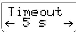
USING THE HTRC 1 REMOTE CONTROL
MODE:The following backlight modes are available:
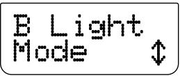
- Off: The backlight will never come ON.
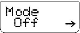
- Sense: The backlight will only come ON if the light sensor detects low light conditions. See also "SENSE LEVEL" discussion below.
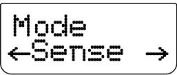
- On: The backlight will come ON any time a key is pressed.

SENSE LEVEL (Sen Lvl): The point where the backlight comes ON in a darkened room. To set this level, go to a dim area where you think the backlight should be activated given such a dark environment condition. Then, press [ENTER] at "B Light - Sen Lvl" menu. The display will show the current sensitivity level. An example is below

If such sensitivity level is alright with you, press [ENTER].
Select "YES" to complete the setting of the sensitivity level.
LIBRARY
The HTRC 1 can store a different library of default NAD codes for each of its DEVICE SELECTOR "pages." If the original default library does not control your NAD CD player, DVD player, or other component, follow the procedure below to change the library code. Please refer as well to the table below for a list of uploaded NAD Library Codes.
Example: Load NAD DVD Player T 585 library codes to HTRC 1's "DVD" device.
1 Press [DVD] in the DEVICE SELECTOR page.
2 Press and hold [TUNER (10+/SETUP)] and [ENTER] buttons. Use [] to scroll to "Library".

3 Press [ENTER].
4 The library code for NAD T585 is "600". Use [<] to toggle to "600". Press [ENTER].
5 Use [] to select between "No" (desired library code is not uploaded) and "Yes" (desired library code is uploaded and saved to the applicable device page.
NOTE
Instead of scrolling through the library list, you can also key-in directly the library code based on the list of Library Codes below.
| LIBRARY CODE | NAD PRODUCT DESCRIPTION | LIBRARY CODE | NAD PRODUCT DESCRIPTION |
| 100 | Receiver/Processor (Discrete ON/OFF) | 300 | Tuner |
| 101 | Receiver/Processor (Toggle ON/OFF) | 301 | L75, L76 Tuner |
| 102 | S170 | 302 | L70 Tuner |
| 103 | L75 | 303 | L53 Tuner |
| 104 | Second Zone Commands (Zone 2) | 304 | L73 Tuner |
| 3112 | Zone 3 | 305 | C425 |
| 4112 | Zone 4 | 306 | C445 |
| 105 | L70 | 307 | Txx5 Series Tuner |
| 106 | L76 | 400 | Tape Deck B |
| 107 | 118 | 401 | TAPE Deck A |
| 108 | L53 | 500 | TV 280 |
| 109 | L73 | 501 | MR13 |
| 110 | Stereo Receiver / Amplifier | 502 | MR20 |
| 111 | Stereo Second Zone | 503 | PMR45 |
| 112 | Txx5 Series | 600 | T535, T562, T585, M55 |
| 200 | CD Player | 601 | T550, L55 |
| 201 | CD Player (old) | 602 | T512, T531, T532, T571, T572 |
| 202 | 5170, 5240, 5340 | 603 | L70, L73 DVD |
| 203 | 5325 | 604 | L56 |
| 204 | 5060 | 605 | T513, T514, T515, T517, T524, T533, T534 |
| 205 | M5 | 606 | L53 DVD |
LEARN
This function allows you to learn IR commands from another remote.
Example: Learning "MENU" function from a TV remote control into the MENU button of HTRC 1's TV device.
Begin by positioning the HTRC 1 "nose-to-nose" with the source remote so that the two devices' infrared windows are about 2 inches apart.

1 Press [TV] in the DEVICE SELECTOR page.
2 Press and hold [TUNER (10+/SETUP)] and [ENTER] buttons. Use [] to scroll to "Learn".
USING THE HTRC 1 REMOTE CONTROL
3 Press [ENTER].

4 Press [MENU] button of HTRC 1 - [MENU] button of the HTRC 1 is where the corresponding [MENU] function key of the TV remote control will be learned.

5 Press and hold the corresponding [MENU] button of the TV remote control until "Success" is shown in the display. (Refer also to "MODE" discussion below).

6 "Success" will be shown in the display if the [MENU] function key is successfully "learned." You can now release the [MENU] button of the TV remote control.
7 Wait until "Success" is extinguished from the display to complete the process.
NOTE
"Failed" will be shown in the lower line display if the "learning" of the desired function key is unsuccessful. Repeat Step 3 - 7 again until "learning" of the desired key is successful.
MODE
There are three modes on how a function key can be learned. Press and hold [TUNER (10+/SETUP)] and [ENTER] buttons. Use [] to scroll to "Learn". Press [ENTER] and then [] to scroll to "Mode". The following are the three modes:


Normal: This is the regular learning mode. A function key is learned until "Success" is shown in the display. The example above is at "Normal" learn mode.

2 Pass: Some remote controls use an IR (infrared) "toggle bit". This means that if you press the same key twice in a row, the IR signal toggles between two different variations of the same command.
At "2 Pass" mode, step 5 and onwards of the above example would be as follows (the same Steps 1 - 4 of the above example applies)
5 Press and hold the corresponding [MENU] button of the TV remote control.

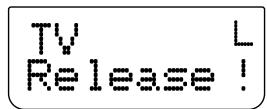
6 Release [MENU] button.
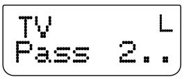
7 "Pass 2" means that you have to press [MENU] button again. Press until "Success" is shown in the display.
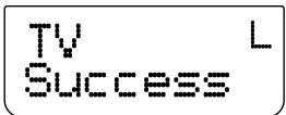
8 "Success" will be shown in the display if the [MENU] function key is successfully "learned." You can now release the [MENU] button of the TV remote control.
9 Wait until "Success" is extinguished from the display to complete the process.
Narrow: Some remote controls use very narrow pulses of IR. If you cannot get your remote to work using the normal or 2 Pass modes, you may want to try this mode. The same example above for "Normal" mode applies to "Narrow" mode.

PUNCH-THROUGH (Pun Thr)
The HTRC 1's "Punch through" function allows you to retain a function key from one DEVICE SELECTOR "page" to another.
Example: Punch-through "SURR MODE" key to the "DVD" page.
1 Press [DVD] in the DEVICE SELECTOR page.
2 Press and hold [TUNER (10+/SETUP)] and [ENTER] buttons. Use [▼] to scroll to "Pun Thr".
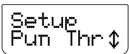
3 Press [ENTER].
4 Press [SURR MODE] button – this is the function key that will be punched through.

5 Press the [AMP] button in the DEVICE SELECTOR page.

6 Use [ / ] to select between "No" (desired punch-through key will not be saved) and "Yes" (desired punch-through key will be saved and process is completed).
NOTE
The HTRC 1's [VOL] keys are pre-programmed as "punched-through" for all Device Select pages: [VOL] will operate the NAD's master-volume regardless of the currently selected device. The [SURR], [CENT] and [SUB] CHANNEL VOLUME controls similarly are pre-programmed as punched-through.
PUNCH-THROUGH MACRO
A stored macro command can also be "punched-through."This provides a way to execute a macro with a single keys press.
Example: Punch-through macro command stored at [0] to the [RTN] key of [BD] page.
1 Press [BD] in the DEVICE SELECTOR page.
2 Press and hold [TUNER (10+/SETUP)] and [ENTER] buttons. Use [▼] to scroll to "Pun Thr".
3 Press [ENTER].
4 Press [RTN] button.
5 Press the [MACRO] button in the DEVICE SELECTOR page.
6 Press [0] button - this is the key where the macro command is associated.
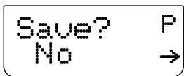
7 "Save" and "No?" are shown in the display. Use [ / ] to select between "No" (desired punch-through macro command will not be saved) and "Yes" (desired punch-through macro command will be saved and process is completed).
EXECUTE PUNCHED-THROUGH MACRO
To recall the punched-through macro command as above example, press [BD] in the DEVICE SELECTOR page and then press [RTN] – the macro command will then be executed.
Refer also to the "MACRO" section below for information on how to setup macros.
COPY
This function allows you to copy functions from one key to another.
Example: Copy "PAUSE"[II] command from DVD page to the AMP [II] button.
1 Press [AMP] in the DEVICE SELECTOR page.
2 Press and hold [TUNER (10+/SETUP)] and [ENTER] buttons. Use [] to scroll to "Copy".
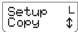
3 Press [ENTER].
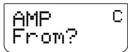
4 Press [DVD] from DEVICE SELECTOR page.

5 Press [II] button - this is the function key that will be copied.

6 Press [AMP] from DEVICE SELECTOR page.
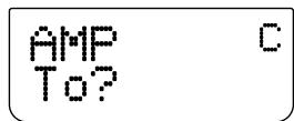
7 Press [II] button - this is the button where the function will be copied.

8 Use [ / ] to select between "No" (desired function key will not be copied) and "Yes" (desired function key will not be copied and process is completed).
NOTE
The copy and punch-through functions are similar. However, if you copy a command and then subsequently delete, or over-write the original (source-key) command, the copied-to key's command remains unchanged. If you punch-through to a command and then delete or over-write the original key, the punched-through functions also change accordingly.
USING THE HTRC 1 REMOTE CONTROL
DELETE
Each key can have several functions types stored. However, only the highest priority type will be active. When you delete a function, a lower priority function type may become active. To completely erase the functionality of a key, you may need to execute the Delete function multiple times. For example; if you delete a learned command, a lower priority command may become active. The order of priority for each function type is:
1 Punch Through
2 Learned
3 Copied Library Command
4 Default Library Command
Example: Delete punch-through "SURR MODE" function key from DVD page (refer to PUNCH-THROUGH example above).
1 Press [DVD] in the DEVICE SELECTOR page.
2 Press and hold [TUNER (10+/SETUP)] and [ENTER] buttons. Use [] to scroll to "Delete".

3 Press [ENTER].

4 Press [SURR MODE] button.

5 Use [ / ] to select between "No" (desired function key will not be deleted) and "Yes" (desired function key is deleted and process is completed).
RENAME
All keys can be renamed except MACRO key.
Example: Rename "Input 1" key of "AMP" page to "DVD".
1 Press [AMP] in the DEVICE SELECTOR page.
2 Press and hold [TUNER (10+/SETUP)] and [ENTER] buttons. Use [▼] to scroll to "Rename".

3 Press [ENTER].

4 Press [1] button.

5 Use [ / ] buttons to select the first character of the name ("D"from the alphabetical list).

6 Press [▶] button to select the character and correspondingly move forward to the next position. (Press [▲] to go back to the previous character). Repeat this process for each character in sequence.
7 Since "DVD" is only three characters and "Input 1" is six character spaces, overlap the remaining characters with a space. Space or blank can also be selected using [/] buttons - scroll up to the blank character.
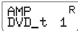
Press [ENTER] when you have finished the renaming sequence.
9 Display shows "Save" and "No" - use [ / ] to select between "No" (new name will not saved) and "Yes" (new name will be saved and process is completed).
MACRO
A "macro" command is a series of two or more remote codes issued automatically from a single keypress. You might use a macro to automate a simple command sequence, such as, "Turn on the DVD player and then press "play." Or you might compose an elaborate macro to power up an entire system, select a source, choose a Listening Mode, and begin playback—again, all from a single keypress. The HTRC 1 can store one macro to all its function keys except MACRO.
Macros will be executed with the same timing as they were recorded. The length of time each command is sent will also correspond to the same length of time the key will be held down while recording.
Example: Record a Macro to the [0] key to turn ON the NAD T 175, Select [Input 1], turn ON the NAD T515 DVD Player, and commence disc playback of the connected Input 1 device (as in the NAD T515 DVD player):
1 Press [AMP] in the DEVICE SELECTOR page.
2 Press and hold [TUNER (10+/SETUP)] and [ENTER] buttons. Use [] to scroll to "Macro".

3 Press [ENTER].
4 Display shows "Macro" and "Key?" - press [0].
5 Press [AMP], [ON], [1], [DVD], [ON] and [ ] (Play). The length of time each command is entered will also correspond to the same time sequence the macro command is executed.
6 Press [MACRO] to end the sequence.

7 Use [ / ] to select between "No" (macro command will not be saved) and "Yes" (macro command will be saved and process is completed).
USING THE HTRC 1 REMOTE CONTROL
EXECUTING MACRO
To execute the above macro example, press [MACRO] and then [0].
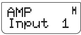


The corresponding macro will run; the display will show each step/ command as the macro is executed. Pressing any other HTRC 1 key while a macro is executing will abort the macro.
By default, when a macro is executed, the currently selected device will be returned to what it was before the macro was executed. However, if the very last button pressed while recording a macro is a DEVICE SELECTOR key, the device will be changed at the end of executing the macro.
RESET
Selecting this option and answering "Yes" to both confirmations will reset all HTRC 1 options to the factory default. All user configurations, macros, and custom device programming will be erased.
1 Press [AMP] in the DEVICE SELECTOR page.
2 Press and hold [TUNER (10+/SETUP)] and [ENTER] buttons. Use [] to scroll to "Reset."
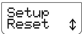
3 Press [ENTER].

4 Use [] to select between "No" (HTRC 1 will not be reset) and "Yes" (HTRC 1 will be reset to its factory defaults). When you select "Yes", another prompt display will be shown.
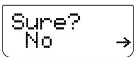
5 Select "Yes" to reset the HTRC 1 and complete the process.
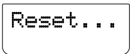
USB INTERFACE
The HTRC 1 allows one to upload and download the configuration through a Windows® PC and NAD's Proprietary HTRC 1 programming software. Use a USB A male to mini USB B male 5-pin cable (not supplied) between your Windows® PC and the HTRC 1. See illustration below on how to connect a USB A male to mini USB B male 5-pin cable to the HTRC 1.
NOTE
Please log onto www.nadelectronics.com for the latest HTRC 1 interface control software. Your custom installer or dealer can assist you in the proper setup and configuration of the mini USB interface and software.
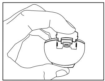
USING THE HTRC 1 REMOTE CONTROL
BATTERY INSTALLATION

Press in and lift tab to remove battery cover out from recess
Place batteries into opening. Ensure the correct polarity is observed
Press battery cover into place until it clicks closed
SLEEP MODE
The Sleep Mode timer will switch the T 175 to Standby mode automatically after a preset number of minutes. Pressing the HTRC 1's SLEEP button once will display the setting of the sleep time increment. Pressing the HTRC 1's SLEEP button a second time within a 3-second period will change the sleep time increment in 15-minute intervals, after which time the T 175 will automatically switch into Standby mode.
To adjust the sleep delay, press the HTRC 1's SLEEP button twice; first to display the sleep time increment, and a second time to change the sleep time increment. The sleep time increment and a "SLEEP" icon will continuously display on the T 175's front panel Vacuum Fluorescent Display (VFD). Each consecutive press increases the sleep time in 15-minute increments from 15 to 90 minutes. To cancel the sleep mode, continue pressing the HTRC 1's SLEEP button until "SLEEP OFF" displays on the VFD. Switching the T 175 to standby from either the HTRC 1's OFF or the T 175's STANDBY button will also cancel the sleep mode
USING THE ZR 4 REMOTE CONTROL
The ZR 4 remote control is a discrete compact remote for controlling the T 175 from various rooms other than the main room. The ZR 4 remote allows full separate control of the source selection irrespective to the main room. This means the zone input may be completely different, audio and video, from the main input and thus corresponding volume levels as well. If one wishes to enjoy the same source, as the main room the ZR 4 remote has a [LOCAL] button to allow simultaneous listening, but with full separate volume levels.
To mute the Zone Volume level, press [MUTE] on the ZR 4. If the "Zone Controls" OSD menu is ON, the Zone "Volume" level section will display "Mute".
The T 175's front fluorescent display will show activity of the zone control so that main room occupants are aware of the zone remote activity. Furthermore if there is no main room activity, only the zone indicator will be active in the T 175's fluorescent display.
NOTE
The ZR 4 remote control will only control Zone 2 applications. Zone 3 and Zone 4 could be configured and managed at the appropriate Zone OSD menu using the front panel navigations keys as well as the corresponding keys on the HTRC 1 remote control. The HTRC 1's "CUSTOM" device is also defaulted to Zone 2 remote control codes.
| CONDITION | POSSIBLE CAUSES | POSSIBLE SOLUTIONS |
| No sound from all channels. | • AC power unplugged. | • Check AC cable connection and outlet. |
| • Power not switched on. | ||
| • Outlet has no power. | ||
| No sound from some channels. | • Faulty/missing cables. | • Check cables. |
| • 'Speaker Configuration' channel (s) set to "OFF". | • Check 'Speaker Configuration' menu. | |
| • Power-amp connections faulty. | • Check power amplifier and cabling. | |
| No sound from surround channels. | • No surround listening mode is engaged. | • Select appropriate listening mode. |
| • Surround-channels set to "OFF" on 'Speaker Configuration' menu. | • Correct 'Speaker Configuration' or 'Speaker Levels' settings. | |
| • Surround-channels level set too low on 'Speaker Levels' menu. | ||
| No sound from Subwoofer. | • Subwoofer is off, not powered or improperly connected. | • Power-up subwoofer, check Sub's AC outlet or check connections. |
| • Subwoofer set to "OFF" on 'Speaker Configuration' menu. | • Correct 'Speaker Configuration' or 'Speaker Levels' settings. | |
| • Sub level set too low on 'Speaker Levels' menu. | ||
| No sound from Center channel. | • Source is a 2/0 (etc.). Dolby Digital or DTS recording without center channel. | • Play a known 5.1-channel recording or select Dolby Pro Logic IIx Music mode. |
| • Center set to "OFF" on 'Speaker Configuration' menu. | • Correct 'Speaker Configuration' or 'Speaker Levels' settings. | |
| • Center level set too low on 'Speaker Levels' menu. | ||
| No Dolby Digital/DTS. | • Source's digital output is not connected to a T 175 digital input. | • Check connections. |
| • Source component not configured for multichannel digital output. | • Check source component setup. | |
| No video display. | • Resolution setting is not supported by the TV/Monitor. | • To restore video display, press and hold both front panel buttons LISTENING MODE and TONE DEFEAT and then release both buttons. |
| T 175 does not respond to HTRC 1 remote. | • Batteries are flat or incorrectly inserted. | • Check batteries. |
| • IR transmitter window on remote or IR A/V Receiver window on T 175 is obstructed. | • Check IR windows and ensure clear line-of-sight from remote to T 175. | |
| • T 175 front panel is in very bright sunlight or ambient light. | • Reduce sunlight/room lighting. | |
| T 175 does not respond to front panel commands or remote control. | • Microprocessor error. | • Power-down the T 175 via the rear panel Power switch and unplug it from the AC outlet. |
| • T 175 may have over heated. | • Wait five minutes, re-connect and power up. | |
| • 12V TRIGGER IN/OUT is set to AUTO position. | • Switch 12V TRIGGER IN/OUT to OFF position. |
Factory defaults for 120V version only: Press simultaneously Source + Front Input/MP
Factory defaults for 230V version only : Press simultaneously Source▶ + Front Input/MP
Audyssey Auto Calibration settings along with other stored presets and settings will all be deleted upon restoring your T 175 to its factory defaults.
SPECIFICATIONS
PREAMPLIFIER SECTION
| Input sensitivity and impedance | 350mV/50KΩ |
| Frequency response | ± 0.5 dB (ref. 20Hz – 20kHz) |
| Total harmonic distortion | <0.08% |
| Input sensitivity | 330mV (ref. 2V) |
| Signal/noise ratio | >93dB (ref.500mV, A-WTD) |
| Signal/noise ratio | >83dB (ref. 2V, A-WTD) |
| Output impedance | <150 ohms |
| Maximum output level | >3.5V |
| TUNER SECTION | |
| AM SECTION | |
| Tuning range | 530kHz -1710kHz (120V version only, 10kHz steps) |
| 531kHz -1602kHz (230V version only, 9kHz steps) | |
| Usable sensitivity | 30dBu |
| S/N ratio | 38dB |
| Total Harmonic Distortion | <3% |
| Loop sensitivity 20dB S/N | 66dBu |
| FM SECTION | |
| Tuning range | 87.50MHz – 108.50MHz |
| Usable sensitivity, MONO | < 16.1dBf |
| IHF (3% THD) | 18dBu |
| S/N Ratio MONO | 60dB |
| S/N Ratio STEREO | 55dB |
| Total Harmonic Distortion, MONO | 0.25% |
| Total Harmonic Distortion, STEREO | 0.5% |
| Channel Separation | 40dB |
| RDS decode sensitivity | 28dBu |
| PHYSICAL SPECIFICATIONS | |
| Unit Dimensions (W x H x D) | 435 x 134 x 353mm (Gross)* |
| Net Weight | 8kg |
| Shipping Weight | 12.5kg |
-
- Gross dimension includes feet, volume knob and extended rear panel terminals.
Specifications are subject to change without notice. For updated documentation and features, please log onto www.NADelectronics.com for the latest information about T 175.
Manufactured under license under U.S. Patent #s: 5,451,942; 5,956,674; 5,974,380; 5,978,762; 6,226,616; 6,487,535; 7,212,872; 7,333,929; 7,392,195; 7,272,567 & other U.S. and worldwide patents issued & pending. DTS is a registered trademark and the DTS logos, Symbol, DTS-HD and DTS-HD Master Audio are trademarks of DTS, Inc. © 1996-2009 DTS, Inc. All Rights Reserved.
Manufactured under license from Dolby Laboratories.
"Dolby," "Pro Logic", and the double-D symbol are registered trademarks of Dolby Laboratories.
HDMI, the HDMI logo and High-Definition Multimedia Interface are trademarks or registered trademarks of HDMI Licensing LLC.
The XM name, XM Ready and related logos are registered trademarks of XM Satellite Radio Inc.
Manufactured under license from Audyssey Laboratories. U.S. and foreign patents pending. Audyssey MultEQ XT is a trade-mark of Audyssey Laboratories.
This product incorporates copyright protection technology that is protected by method claims of certain U.S. patents and other intellectual property rights owned by Macrovision Corporation and other rights owners. Use of this copyright protection technology must be authorized by Macrovision Corporation, and is intended for home and other limited viewing uses only unless otherwise authorized by Macrovision Corporation. Reverse engineering or disassembly is prohibited.

www.NADelectronics.com
©2009 NAD ELECTRONICS INTERNATIONAL A DIVISION OF LENBROOK INDUSTRIES LIMITED
All rights reserved. NAD and the NAD logo are trademarks of NAD Electronics International, a division of Lenbrook Industries Limited. No part of this publication may be reproduced, stored or transmitted in any form without the written permission of NAD Electronics International.