CTM1018 - Multifunction tool Ferm - Free user manual and instructions
Find the device manual for free CTM1018 Ferm in PDF.


| Product type | Oscillating multi-tool |
| Brand | Ferm |
| Model | CTM1018 |
| Supply voltage | 230 V ~ 50 Hz |
| Power consumption | 300 W |
| No-load speed (oscillations) | 11,000 – 20,000 min⁻¹ |
| Oscillation angle | 3.2° (left/right) |
| Weight | 1.2 kg |
| Dimensions (L × W × H) | 310 × 85 × 85 mm |
| Main functions | Sawing, sanding, scraping, flush cutting |
| Included accessories | Segmented saw blade, plunge saw blade, sanding pad (3 grits), scraper |
| Accessory fixation system | Keyless (quick clamping) |
| Speed controller | Yes, adjustment wheel |
| Switch | On/off switch with continuous lock |
| Work light | Integrated LED |
| Dust extraction connection | Yes, vacuum adapter (35 mm diameter) |
| Safety class | II (double insulation) |
| Sound pressure level (LpA) | 78 dB(A) |
| Sound power level (LwA) | 89 dB(A) |
| Vibration (total value ah) | 5.2 m/s² (sanding), 7.1 m/s² (sawing) |
| Maintenance and cleaning | Clean with a dry cloth; do not use abrasive products; lubricate moving parts if necessary |
| Spare parts and repairability | Available through Ferm customer service; replaceable motor brushes |
| General information | Manual freely downloadable from notice-facile.com |
Frequently Asked Questions - CTM1018 Ferm
User questions about CTM1018 Ferm
0 question about this device. Answer the ones you know or ask your own.
Ask a new question about this device
Download the instructions for your Multifunction tool in PDF format for free! Find your manual CTM1018 - Ferm and take your electronic device back in hand. On this page are published all the documents necessary for the use of your device. CTM1018 by Ferm.
USER MANUAL CTM1018 Ferm

natural_image
Product photo of a FERM electric drill pen tool with various tools and components (no visible text or symbols)CTM1018
EN Original instructions 05
NL Vertaling van de oorspronkelijke gebruiksaanwijzing 11
FR Traduction de la notice originale 18
DE Übersetzung der Originalbetriebsanleitung 25
PL Tłumaczenie instrukcji oryginalnej 33
CS Překlad původního návodu k používání 40


Fig. 3

natural_image
Four types of light gray icons on rods, including a cylindrical object and four conical shapes (no text or symbols)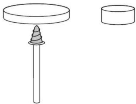
natural_image
Simple line drawing of a pin with a spiral base and a cylindrical object (no text or symbols)Fig. 5Fig. 4

natural_image
Three mechanical components: a cylindrical shaft, a hollow cylinder, and a separate curved component (no text or symbols)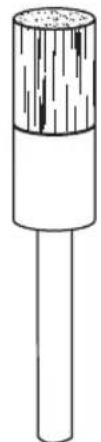
natural_image
Simple line drawing of a cylindrical object with a textured top and shaft (no text or symbols)Fig. 7 Fig. 6

natural_image
Five different types of dental or surgical tools shown in line drawings, labeled Fig. 8 (no text or symbols on the tools themselves)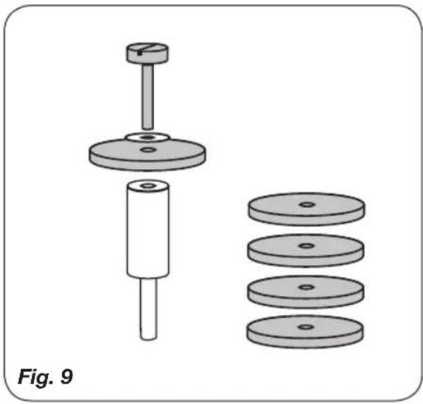
natural_image
Mechanical assembly diagram showing a cylindrical component with three circular plates, labeled Fig. 9 (no text or symbols on the components themselves)COMBITOOL CTM1018
Thank you for buying this Ferm product.
By doing so you now have an excellent product, delivered by one of Europe's leading suppliers. All products delivered to you by Ferm are manufactured according to the highest standards of performance and safety. As part of our philosophy we also provide an excellent customer service, backed by our comprehensive warranty. We hope you will enjoy using this product for many years to come.
1. SAFETY INSTRUCTIONS

Read the enclosed safety warnings, the additional safety warnings and the instructions. Failure to follow the safety warnings and the instructions may result in electric shock, fire and/or serious injury. Save the safety warnings and the instructions for future reference.
The following symbols are used in the user manual or on the product:

Denotes risk of personal injury, loss of life or damage to the tool in case of nonobservance of the instructions in this manual.

Risk of electric shock

Variable speed control

Indoor use only

Wear ear and eye protection

Wear a dust mask

Do not press the spindle lock button while the motor is running.

Class II machine - Double insulation - You don't need any earthed plug.

Max temperature 40°C

Do not throw the battery into fire

Do not throw the battery into water

Do not dispose of the product in unsuitable containers.

Separate collection for Li-ion battery.

The product is in accordance with the applicable safety standards in the European directives.
Specific safety instructions
a) This power tool is intended to function as a grinder, sander, wire brush, polisher, carving or cut-off tool. Read all safety warnings, instructions, illustrations and specifications provided with this power tool. Failure to follow all instructions listed below may result in electric shock, fire and/or serious injury.
c) Do not use accessories which are not specifically designed and recommended by the tool manufacturer. Just because the accessory can be attached to your power tool, it does not assure safe operation.
d) The rated speed of the grinding accessories must be at least equal to the maximum speed marked on the power tool. Grinding accessories running faster than their rated speed can break and fly apart.
e) The outside diameter and the thickness of your accessory must be within the capacity rating of your power tool. Incorrectly sized accessories cannot be adequately controlled.
f) The arbour size of wheels, sanding drums or any other accessory must properly fit the spindle or collet of the power tool. Accessories that do not match the mounting hardware of the power tool will run out of balance, vibrate excessively and can lead to loss of control of the power tool.
g) Mandrel mounted wheels, sanding drums, cutters or other accessories must be fully
inserted into the collet or chuck. If the mandrel is insufficiently held and/or the overhang of the wheel is too long, the mounted wheel may become loose and be ejected at high velocity.
h) Do not use a damaged accessory. Before each use inspect the accessory such as abrasive wheels for chips and cracks, sanding drum for cracks, tear or excess wear, wire brush for loose or cracked wires. If power tool or accessory is dropped, inspect for damage or install an undamaged accessory. After inspecting and installing an accessory, position yourself and bystanders away from the plane of the rotating accessory and run the power tool at maximum no-load speed for one minute. Damaged accessories will normally break apart during this test time.
i) Wear personal protective equipment. Depending on application, use face shield, safety goggles or safety glasses. As appropriate, wear dust mask, hearing protectors, gloves and workshop apron capable of stopping small abrasive or workpiece fragments. The eye protection must be capable of stopping flying debris generated by various operations. The dust mask or respirator must be capable of filtrating particles generated by your operation. Prolonged exposure to high intensity noise may cause hearing loss.
j) Keep bystanders a safe distance away from work area. Anyone entering the work area must wear personal protective equipment.
Fragments of workpiece or of a broken accessory may fly away and cause injury beyond immediate area of operation.
k) Hold power tool by insulated gripping surfaces only, when performing an operation where the cutting accessory may contact hidden wiring. Cutting accessory contacting a "live" wire may make exposed metal parts of the power tool "live" and could give the operator an electric shock.
I) Always hold the tool firmly in your hand(s) during the start-up. The reaction torque of the motor, as it accelerates to full speed, can cause the tool to twist.
m) Use clamps to support workpiece whenever practical. Never hold a small workpiece in one hand and the tool in the other hand while in use. Clamping a small workpiece allows you to use your hand(s) to control the tool. Round
material such as dowel rods, pipes or tubing have a tendency to roll while being cut, and may cause the bit to bind or jump toward you.
n) Position the cord clear of the spinning accessory. If you lose control, the cord may be cut or snagged and your hand or arm may be pulled into the spinning accessory.
o) Never lay the power tool down until the accessory has come to a complete stop. The spinning accessory may grab the surface and pull the power tool out of your control.
p) After changing the bits or making any adjustments, make sure the collet nut, chuck or any other adjustment devices are securely tightened. Loose adjustment devices can unexpectedly shift, causing loss of control, loose rotating components will be violently thrown.
q) Do not run the power tool while carrying it at your side. Accidental contact with the spinning accessory could snag your clothing, pulling the accessory into your body.
r) Regularly clean the power tool's air vents. The motor's fan will draw the dust inside the housing and excessive accumulation of powdered metal may cause electrical hazards.
s) Do not operate the power tool near flammable materials. Sparks could ignite these materials.
t) Do not use accessories that require liquid coolants. Using water or other liquid coolants may result in electrocution or shock.
Kickback and related warnings
Kickback is a sudden reaction to a pinched or snagged rotating wheel, sanding band, brush or any other accessory. Pinching or snagging causes rapid stalling of the rotating accessory which in turn causes the uncontrolled power tool to be forced in the direction opposite of the accessory's rotation.
For example, if an abrasive wheel is snagged or pinched by the workpiece, the edge of the wheel that is entering into the pinch point can dig into the surface of the material causing the wheel to climb out or kick out. The wheel may either jump toward or away from the operator, depending on direction of the wheel's movement at the point of pinching. Abrasive wheels may also break under these conditions.
Kickback is the result of power tool misuse and/or incorrect operating procedures or conditions and can be avoided by taking proper precautions as given below.
a) Maintain a firm grip on the power tool and position your body and arm to allow you to resist kickback forces. The operator can control kickback forces, if proper precautions are taken.
b) Use special care when working corners, sharp edges etc. Avoid bouncing and snagging the accessory. Corners, sharp edges or bouncing have a tendency to snag the rotating accessory and cause loss of control or kickback.
c) Do not attach a toothed saw blade. Such blades create frequent kickback and loss of control.
d) Always feed the bit into the material in the same direction as the cutting edge is exiting from the material (which is the same direction as the chips are thrown). Feeding the tool in the wrong direction causes the cutting edge of the bit to climb out of the work and pull the tool in the direction of this feed.
e) When using rotary files, cut-off wheels, high-speed cutters or tungsten carbide cutters, always have the work securely clamped. These wheels will grab if they become slightly canted in the groove, and can kickback. When a cut-off wheel grabs, the wheel itself usually breaks. When a rotary file, high-speed cutter or tungsten carbide cutter grabs, it may jump from the groove and you could lose control of the tool.
Additional safety instructions for grinding and cutting-off operations Safety warnings specific for grinding and abrasive cutting-off operations:
a) Use only wheel types that are recommended for your power tool and only for recommended applications. For example: do not grind with the side of a cut-off wheel. Abrasive cut-off wheels are intended for peripheral grinding, side forces applied to these wheels may cause them to shatter.
b) For threaded abrasive cones and plugs use only undamaged wheel mandrels with an unrelieved shoulder flange that are of correct size and length. Proper mandrels will reduce the possibility of breakage.
c) Do not "jam" a cut-off wheel or apply excessive pressure. Do not attempt to make an excessive depth of cut. Overstressing the
wheel increases the loading and susceptibility to twisting or snagging of the wheel in the cut and the possibility of kickback or wheel breakage.
d) Do not position your hand in line with and behind the rotating wheel. When the wheel, at the point of operation, is moving away from your hand, the possible kickback may propel the spinning wheel and the power tool directly at you.
e) When wheel is pinched, snagged or when interrupting a cut for any reason, switch off the power tool and hold the power tool motionless until the wheel comes to a complete stop. Never attempt to remove the cut-off wheel from the cut while the wheel is in motion otherwise kickback may occur. Investigate and take corrective action to eliminate the cause of wheel pinching or snagging.
f) Do not restart the cutting operation in the workpiece. Let the wheel reach full speed and carefully re-enter the cut. The wheel may bind, walk up or kickback if the power tool is restarted in the workpiece.
g) Support panels or any oversized workpiece to minimize the risk of wheel pinching and kickback. Large workpieces tend to sag under their own weight. Supports must be placed under the workpiece near the line of cut and near the edge of the workpiece on both sides of the wheel.
h) Use extra caution when making a “pocket cut” into existing walls or other blind areas. The protruding wheel may cut gas or water pipes, electrical wiring or objects that can cause kickback.
Additional safety instructions for wire brushing operations
Safety warnings specific for wire brushing operations:
a) Be aware that wire bristles are thrown by the brush even during ordinary operation. Do not overstress the wires by applying excessive load to the brush. The wire bristles can easily penetrate light clothing and/or skin.
b) Allow brushes to run at operating speed for at least one minute before using them. During this time no one is to stand in front or in line with the brush. Loose bristles or wires will be discharged during the run-in time.
c) Direct the discharge of the spinning wire brush away from you. Small particles and tiny wire fragments may be discharged at high velocity during the use of these brushes and may become imbedded in your skin.
Battery tool use and care
a) Recharge only with the charger specified by the manufacturer. A charger that is suitable for one type of battery pack may create a risk of fire when used with another battery pack.
b) Use power tools only with specifically designated battery packs. Use of any other battery packs may create a risk of injury and fire.
c) When battery pack is not in use, keep it away from other metal objects, like paper clips, coins, keys, nails, screws or other small metal objects, that can make a connection from one terminal to another. Shorting the battery terminals together may cause burns or a fire.
d) Under abusive conditions, liquid may be ejected from the battery; avoid contact. If contact accidentally occurs, flush with water. If liquid contacts eyes, additionally seek medical help. Liquid ejected from the battery may cause irritation or burns.
Service
a) Have your power tool serviced by a qualified repair person using only identical replacement parts. This will ensure that the safety of the power tool is maintained.
For the charger Intended use
Charge only rechargeable battery packs. Other types of batteries may burst causing personal injury and damage.
a) The appliance is not to be used by persons (including children) with reduced physical, sensory or mental capabilities, or lack of experience and knowledge, unless they have been given supervision or instruction
b) Children being supervised not to play with the appliance
c) Do not recharging non-rechargeable batteries!
d) During charging, batteries must be placed in the well ventilated area!
e) Integrated batteries may only be removed for disposal by qualified personnel. Opening the housing shell can destroy the power tool. To remove the battery from the power tool, press the On/Off switch (5) until the battery is fully discharged. Unscrew the screws on the housing and remove the housing shell in order to remove the battery. To prevent a short circuit, disconnect the connectors on the battery one at a time and then isolate the poles. Even when fully discharged, the battery still contains a residual capacity, which can be released in case of a short circuit.
Electrical safety
When using electric machines always observe the safety regulations applicable in your country to reduce the risk of fire, electric shock and personal injury. Read the following safety instructions and also the enclosed safety instructions.

Always check that the power supply corresponds to the voltage on the rating plate.

Your machine is double insulated, therefore no earthwire is required.
2. MACHINE INFORMATION
Intended use
This power tool is intended to function as a grinder, sander, wire brush, polisher, carving or cut-off tool. This combitool is great for editing of materials like wood, plastic, stone, shell aluminium, brass and steel. Always use the proper accessories and speed setting.
Technical specifications
| Rechargeable Battery | 8V Li-ion 900mAh | |
| Charger | CDA1111 | |
| Input of charger | 100-240V~50/60Hz 0.2A | |
| Output of charger | 9.0V d.c. 0.5A | |
| Battery charging time | 2-3hours | |
| Maximum disc diameter | 35 mm | |
| No load speed | 5.000–25.000/min | |
| Capacity of spring chuck | 3.2 mm | |
| Weight | 0.26 | |
| Lpa (Sound pressure level) | 76+3 dB(A) | |
| Lwa (Sound power level) | 87+3 dB(A) | |
| Vibration | 2.35+1.5 m/s ^2 | |
kg
Vibration level
The vibration emission level stated in this instruction manual has been measured in accordance with a standardised test given in EN 60745; it may be used to compare one tool with another and as a preliminary assessment of exposure to vibration when using the tool for the applications mentioned.
- using the tool for different applications, or with different or poorly maintained accessories, may significantly increase the exposure level.
- the times when the tool is switched off or when it is running but not actually doing the job, may significantly reduce the exposure level.
Protect yourself against the effects of vibration by maintaining the tool and its accessories, keeping your hands warm, and organizing your work patterns.
Description
The numbers in the following text refer to the pictures on page 2-3
- Collet chuck
- LED work light
- Spindle lock
4A. Speed adjustment button "+"
4B. Speed adjustment button “-” - On/off button
- Speed indication lights
- Charger indication light
- Chuck spanner
3. ASSEMBLY

Always make sure the machine is turned off before mounting an accessory.

Warning! Change accessories by inserting an accessory into the collet (or chuck) as far possible to minimize run out and unbalance.
Assembly of accessories
Fig. 2
Press down the spindle lock (3) and hold it down. Using the chuck spanner (8) you can undo the collet chuck (1). Put the accessory in its place. Hold down the spindle lock when you fasten the collet chuck with the chuck spanner.

Do not press the spindle lock button while the motor is running.
4. OPERATION
Switch on the machine by pressing the on/off button (5).
With the speed adjustment button “+”(4A) or “-”(4B) you can regulate the speed of the Combitool. Do not put the machine down when the motor is still running. Do not place the machine on a dusty surface. Dust particles may enter the mechanism.

Too high a load at a low speed of the Combitool can burn out the engine.
The battery must be charged before first use.
Charging the device (with the charger)
- Plug the charger plug into an electrical outlet and wait for a while. The charger indication light (7) will lighten up and show the charging status.
LED Charger status
Red Battery charging in progress
Green Battery charging finished, battery fully charged
- After the battery is fully charged remove the charger plug from the outlet and remove the small plug from the device.
Holding and guiding the tool
Fig. 3
• For precision work (engraving): pencil grip (A)
- For rough work (grinding): paring knife hand grip (B)
- When you need to keep the tool parallel to the work surface (e.g. using a cut-off wheel): 2 hand golf grip (C)
Optimal use of the combi tool and its accessories
Fig. 1
For optimal use of the accessories use the correct speed. You can refer to the overview
"Recommended speed setting" below to determine the correct speed, based on the material being worked on and the type of accessory being used. This overview enables you to select both correct accessory and the optimum speed.
The 5 speeds indication lights (6) are equal to the numbers 1, 2, 3, 4 and 5 in the overview "Recommended speed setting".
Ultimately, the best way to determine the correct speed for work on any material is to practice on a piece of scrap.
Recommended speed setting
Grinding stones
| Fig. 4 | |||
| Material | Speed | setting | |
| Stone, shell | 1-3 | ||
| Steel | 3-5 | ||
| Aluminium, brass | 2-4 | ||
| Plastic | 1-3 | ||
Felt wheels and tip
Fig. 5 The felt wheels or tip should be screwed on the mandrel.
| Material | Speed | setting |
| Steel | 3-5 | |
| Aluminium, brass 2-4 | ||
| Plastic | 3-5 |
Sanding bands and disc (sanding disc not included)
| Fig. 6 | ||
| Material | Speed | setting |
| Wood | 4-5 | |
| Steel | 1-3 | |
| Aluminium, brass 2-4 | ||
| Plastic | 1-3 | |
Bristol brush
| Fig. 7 | |||
| Material | Speed | setting | |
| Stone, shell | 2-4 | ||
| Aluminium, brass | 2-4 | ||
High speed cutter, Diamond wheel point and Drill
| Fig. 8 | |||
| Material | Speed | setting | |
| Stone, shell | 5 | ||
| Steel | 2-4 | ||
| Aluminium, brass | 4-5 | ||
| Plastic | 1-3 | ||
Abrasive disc
| Fig. 9 | ||
| Material | Speed | setting |
| Steel | 3-5 | |
| Aluminium, brass 2-4 | ||
| Plastic | 1-3 | |
5. MAINTENANCE

Make sure that the machine is not live when carrying out maintenance work on the motor.
Keep the ventilation slots of the machine clean to prevent overheating of the engine. Regularly clean the machine housing with a soft cloth, preferably after each use. Keep the ventilation slots free from dust and dirt. If the dirt does not come off use a soft cloth moistened with soapy water. Never use solvents such as petrol, alcohol, ammonia water, etc. These solvents may damage the plastic parts. Please clean the tool immediately after use.
ENVIRONMENT

Damaged and/or disposed of electrical or electronic devices must be dropped off at recycling stations intended for that purpose.
Only for EC countries
Do not dispose of power tools into domestic waste. According to the European Guideline 2012/19/EU for Waste Electrical and Electronic Equipment and its implementation into national right, power tools that are no longer usable must be collected separately and disposed of in an environmentally friendly way.
WARRANTY
Read the warranty conditions on the separately supplied warranty card.
The product and the user manual are subject to change. Specifications can be changed without further notice.
COMBITOOL
CTM1018
2. INFORMATIONS RELATIVES LA MACHINE
Utilisation prevue
The felt wheels or tip should be screwed on the mandrel.

- CTM1018
- COMBITOOL CTM1018
- Thank you for buying this Ferm product.
- SAFETY INSTRUCTIONS
- Specific safety instructions
- Kickback and related warnings
- Additional safety instructions for grinding and cutting-off operations Safety warnings specific for grinding and abrasive cutting-off operations:
- Additional safety instructions for wire brushing operations
- Battery tool use and care
- Service
- For the charger Intended use
- Electrical safety
- MACHINE INFORMATION
- Intended use
- Vibration level
- Description
- ASSEMBLY
- Assembly of accessories
- Fig. 2
- OPERATION
- The battery must be charged before first use.
- Charging the device (with the charger)
- LED Charger status
- Holding and guiding the tool
- Fig. 3
- Optimal use of the combi tool and its accessories
- Fig. 1
- Recommended speed setting
- MAINTENANCE
- ENVIRONMENT
- Only for EC countries
- WARRANTY
- COMBITOOL
- INFORMATIONS RELATIVES LA MACHINE
- Utilisation prevue
Brand : Ferm
Model : CTM1018
Category : Multifunction tool