
XB110HL1 - Household Fan BROAN - Free user manual and instructions
Find the device manual for free XB110HL1 BROAN in PDF.


| Product Type | Domestic Exhaust Fan |
| Brand | Broan |
| Model | XB110HL1 |
| Dimensions (W x D x H) | 12 x 12 x 6 inches |
| Weight | 5.5 lbs |
| Power Supply | 120V, 60Hz, 0.5A |
| Airflow (CFM) | 70 CFM |
| Noise Level (Sones) | 1.5 Sones |
| Installation Type | Ceiling or Wall Mount |
| Duct Size | 4 inches |
| Housing Material | Galvanized Steel |
| Grille Material | White Polymer |
| Certifications | UL Listed, ETL Certified |
| Warranty | 1 Year Limited |
| Maintenance | Clean grille and fan blades with damp cloth |
| Spare Parts Availability | Available through Broan dealers |
| Energy Efficiency | Energy Star Qualified |
| Motor Type | Permanently Lubricated, Low Noise |
| Operating Temperature | Up to 104°F (40°C) |
Frequently Asked Questions - XB110HL1 BROAN
User questions about XB110HL1 BROAN
0 question about this device. Answer the ones you know or ask your own.
Ask a new question about this device
Download the instructions for your Household Fan in PDF format for free! Find your manual XB110HL1 - BROAN and take your electronic device back in hand. On this page are published all the documents necessary for the use of your device. XB110HL1 by BROAN.
USER MANUAL XB110HL1 BROAN
READ AND SAVE THESE INSTRUCTIONS
Installer: leave this guide with homeowner.
Register your product online at www.broan.com/register.
XB110HL1
X1 | Single-Speed Ventilation Fan with Dimmable Light and Humidity Sensor
INSTALLATION GUIDE
natural_image
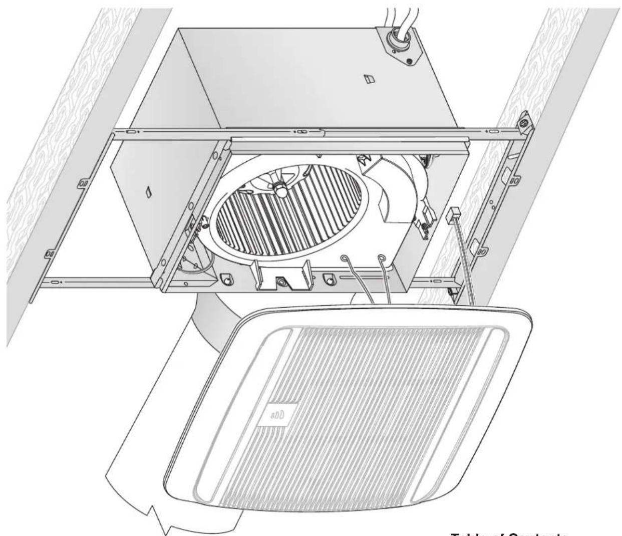
Technical line drawing of a mechanical assembly with internal components and mounting brackets (no text or symbols)Easy installation in both new construction and retrofit
Table of Contents
Warnings and Cautions 2
Typical Installation 2
New Construction Installation 3
Retrofit Installation 7
Operation 12
Cleaning and Maintenance 13
Troubleshooting 13
Service Parts 13
Warranty 14
WARNING


TO REDUCE THE RISK OF FIRE, ELECTRIC SHOCK, OR INJURY TO PERSONS, OBSERVE THE FOLLOWING:
- Use this unit only in the manner intended by the manufacturer. If you have questions, contact the manufacturer at the address or telephone number listed in the warranty.
- Before servicing or cleaning unit, switch power off at service panel and lock the service disconnecting means to prevent power from being switched on accidentally. When the service disconnecting means cannot be locked, securely fasten a prominent warning device, such as a tag, to the service panel.
- Installation work and electrical wiring must be done by a qualified person(s) in accordance with all applicable codes and standards, including fire-rated construction codes and standards.
- Sufficient air is needed for proper combustion and exhausting of gases through the flue (chimney) of fuel burning equipment to prevent backdrafting. Follow the heating equipment manufacturer's guideline and safety standards such as those published by the National Fire Protection Association (NFPA), and the American Society for Heating, Refrigeration and Air Conditioning Engineers (ASHRAE), and the local code authorities.
- When cutting or drilling into wall or ceiling, do not damage electrical wiring and other hidden utilities.
- Ducted fans must always be vented to the outdoors.
- Use only ON/OFF switch, mechanical timer or relay-switched control.
- Acceptable for use over a tub or shower when connected to a GFCI (Ground Fault Circuit Interrupter) - protected branch circuit.
- This unit must be grounded.
CAUTION

- For general ventilating use only. Do not use to exhaust hazardous or explosive materials and vapors.
- This product is designed for installation in flat ceilings. Sensor will not function reliably if product is not installed in flat ceiling. DO NOT MOUNT THIS PRODUCT IN A WALL.
- To avoid motor bearing damage and noisy and/or unbalanced impellers, keep drywall spray, construction dust, etc. off power unit.
- Please read specification label on product for further information and requirements.
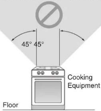
NOT FOR USE IN A COOKING AREA
Do not install above or inside this area
Typical Installation
• Installation is the same for:
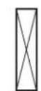
Joists
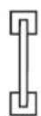
I-Joists
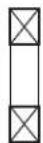
Trusses
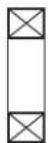
- Fits in 2" x 8" ceiling construction.
- Infinitely adjust the fan position between joists from 14" to 24" on center.
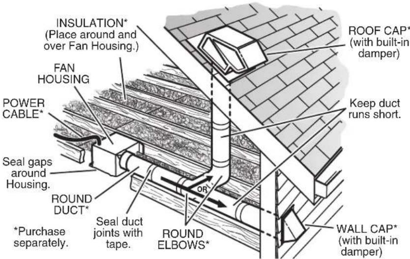
The ducting from this fan to the outside of the building has a strong effect on the air flow, noise and energy use of the fan. Use the shortest, straighest duct routing possible for best performance, and avoid installing the fan with smaller ducts than recommended. Insulation around the ducts can reduce energy loss and inhibit mold growth. Fans installed with existing ducts may not achieve their rated airflow.
6-inch round rigid metal duct is recommended for best performance.
New Construction Installation
Tools needed
• Power screwdriver with a Phillips bit
- Phillips screwdriver
- Flathead screwdriver
- Pliers
- Wire insulation stripper
- Wire cutter
Materials needed
- 6" round metal ducting recommended for best performance.
Use of other ducting is acceptable but may impact performance. - Roof cap or wall cap (built-in damper recommended)
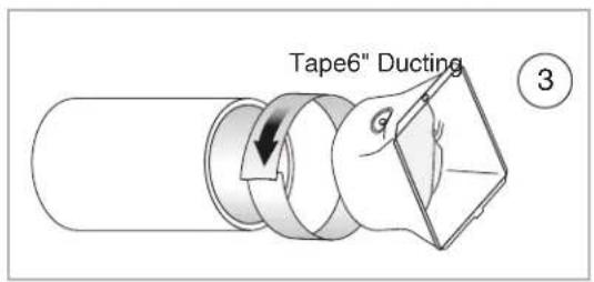
- Tape to seal duct connections
• Electrical wiring and supplies per local code requirements
1 Remove Packaging
Parts Bag holds Knockout Plate and six (6) screws
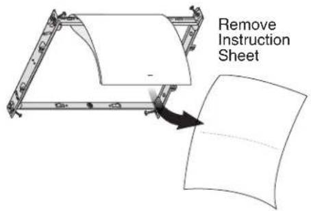
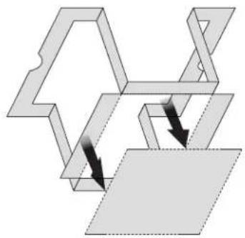
Punch out Mask from packaging. See Step 6.
natural_image
Pure mechanical assembly diagram showing interlocking parts without any text, numbers, or symbols2 Install Mounting Frame
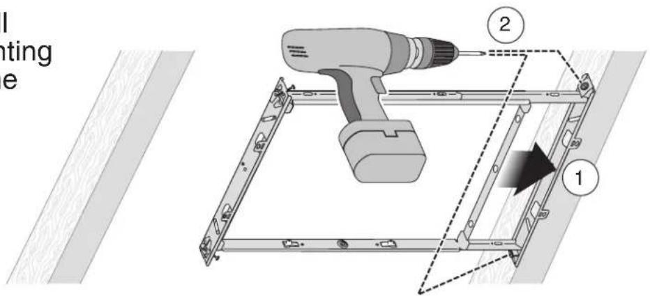
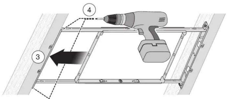
New Construction Installation
3 Snap-in and
Secure Housing
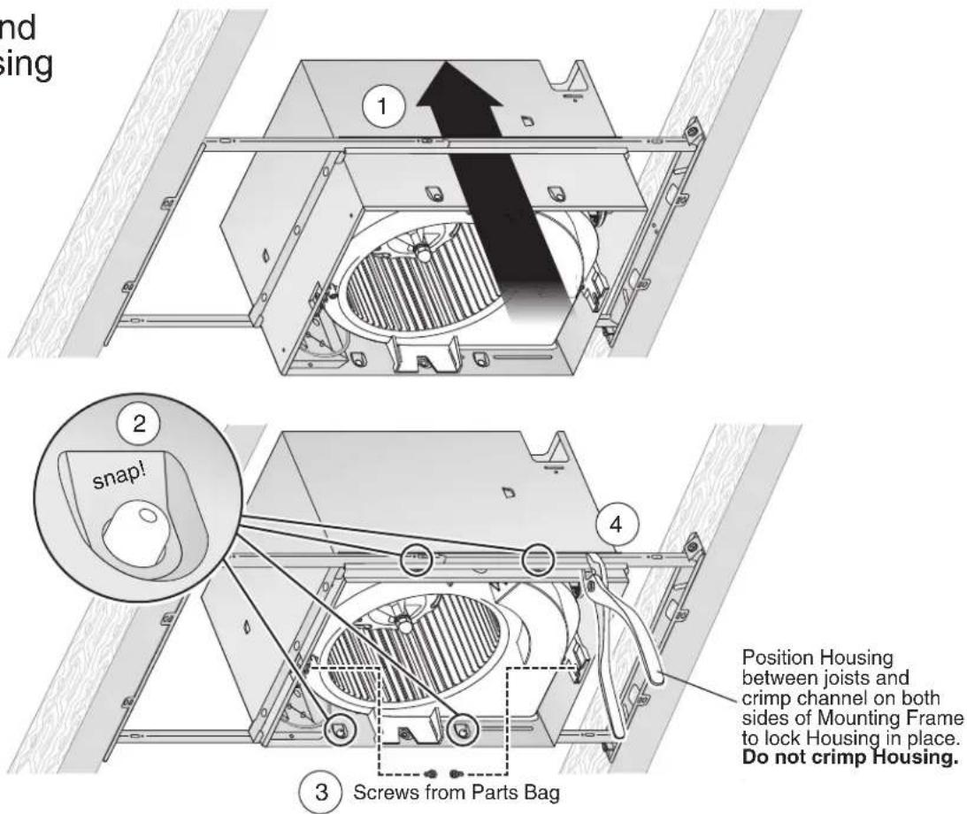
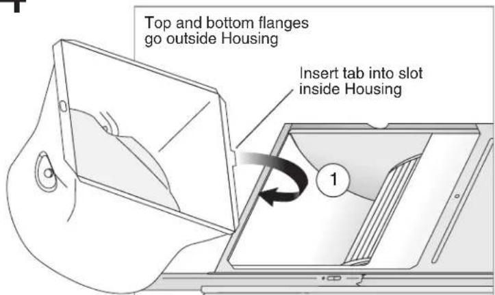
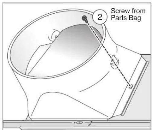
4 Attach Duct Connector and Ducting
New Construction Installation
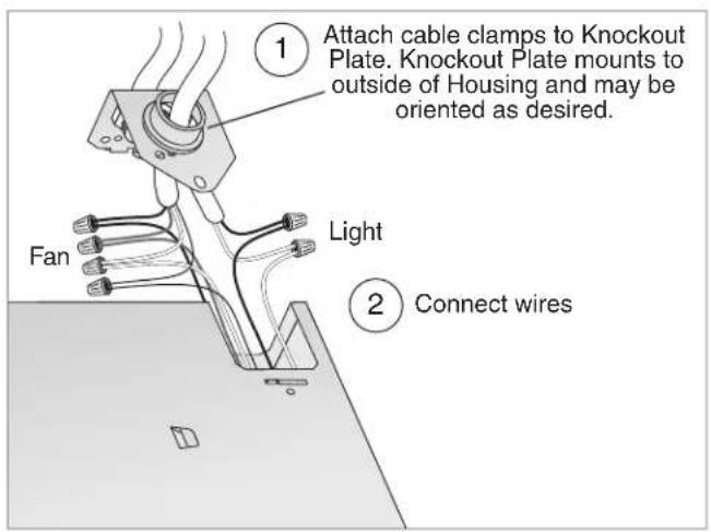
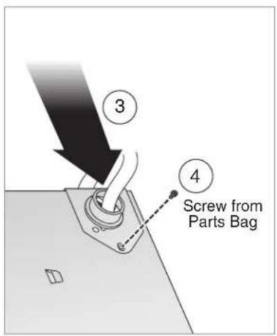
5 Connect Wires and Install Knockout Plate • Run 120VAC electrical wiring to the installation location
- Run 120VAC electrical wiring to the installation location.
- Use proper UL-approved connectors to secure wiring to the Knockout Plate provided in Parts Bag.
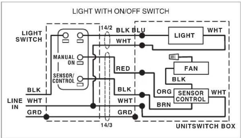
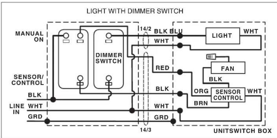
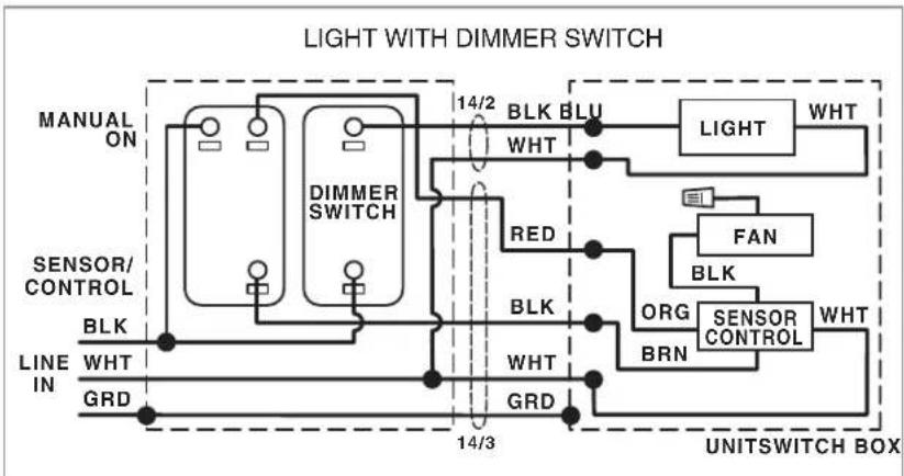
- Connect wires as shown in wiring diagram.
flowchart
graph TD
    A["Light SWITCH"] --> B["MANUAL ON"]
    B --> C["SENSOR/CONTROL"]
    C --> D["RED"]
    D --> E["BLK"]
    E --> F["WHT"]
    F --> G["GRD"]
    G --> H["BRN"]
    H --> I["ORG"]
    I --> J["SENSOR CONTROL"]
    J --> K["WHT"]
    K --> L["FAN"]
    L --> M["LIGHT"]
    M --> N["WHT"]
    N --> O["UNIT SWITCH BOX"]
    style A fill:#f9f,stroke:#333
    style O fill:#ccf,stroke:#333
flowchart
graph TD
    A["MANUAL ON"] --> B["DIMMER SWITCH"]
    C["SENSOR/CONTROL"] --> B
    D["LINE IN"] --> B
    E["GRD"] --> B
    B --> F["14/2 BLK BLU WHT"]
    B --> G["RED"]
    B --> H["BLK"]
    B --> I["WHT"]
    B --> J["GRD"]
    K["LIGHT"] --> L["WHT"]
    M["FAN"] --> N["BLK"]
    O["ORG"] --> P["BRN"]
    Q["SENSOR CONTROL"] --> R["WHT"]
    S["UNITSWITCH BOX"] --> T["14/3"]
• See OPERATION section on page 12 for details.
- SENSOR/CONTROL switch turns humidity control on for automatic operation and off for fan cleaning and maintenance purposes.
- MANUAL-ON switch directly turns fan on/off.
- MANUAL-ON switch is not required to manually turn fan on (see page 10).
- SENSOR/CONTROL switch may be located where it is not easily accessed for everyday usage; it may need to be labeled and located where it can't be turned on without being seen from fan to comply with local and national codes.
New Construction Installation

Insert Mask and finish Ceiling
• Install ceiling material.
- Cut out around Housing.
CAUTION


IN ORDER TO PREVENT
MOTOR/CONTROL DAMAGE:
If the blower was unplugged, power must be disconnected (see page 2, WARNING item 2) before inserting motor plugs into control assembly.
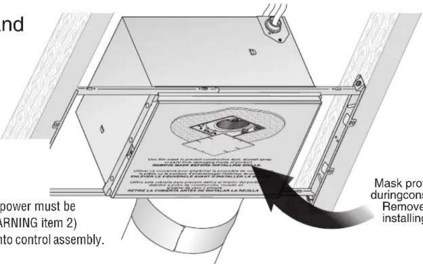
Mask protects unit duringconstruction. Removebefore installingGrille.

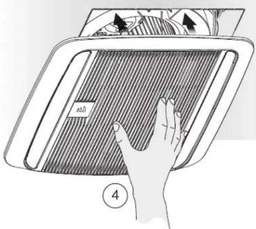
Install Grille
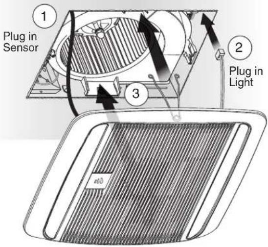
natural_image
Illustration of a hand pressing down on a textured surface with arrows and symbols (no readable text or labels)Retrofit Installation
Tools needed
• Power screwdriver with a Phillips bit
- Phillips screwdriver
- Flathead screwdriver
- Pliers
- Wire insulation stripper
- Wire cutter
- Ruler
- Pencil
- Drywall saw
- Claw hammer or pry bar
- Utility knife
Materials needed
- Tape to seal duct connections
- Existing rigid duct will require the addition of a short length of flexible duct
• Electrical wiring and supplies per local code requirements
1 Remove Packaging
Parts Bag holds Knockout Plate and six (6) screws
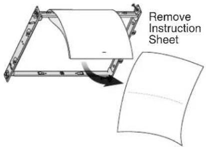
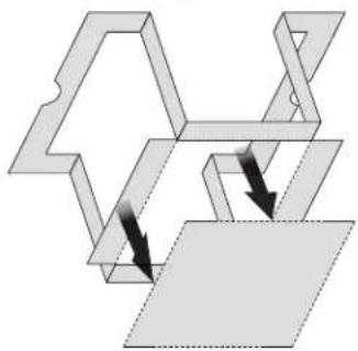
Punch out Mask from packaging. See Step 12.
natural_image
Pure mechanical assembly diagram showing two connected components with arrows indicating direction (no text or symbols)2 Switch Off Power WARNING
Before removing existing fan, switch power off at service panel and lock the service disconnecting means to prevent power from being switched on accidentally. When the service disconnecting means cannot be locked, securely fasten a prominent warning device, such as a tag, to the service panel.
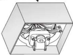
3 Enlarge Ceiling Opening and Remove Existing Fan
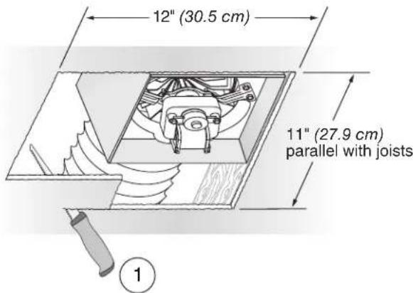
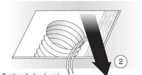
Existing ductwork and wiring left in place
natural_image
Technical diagram of a mechanical assembly inside a transparent box (no text or symbols visible)4 Examine Wiring Examine the existing wiring
Examine the existing wiring to make sure it is not damaged. If any damage is found, DO NOT CONTINUE INSTALLATION of this product. Contact a qualified person(s) for repair.
Retrofit Installation
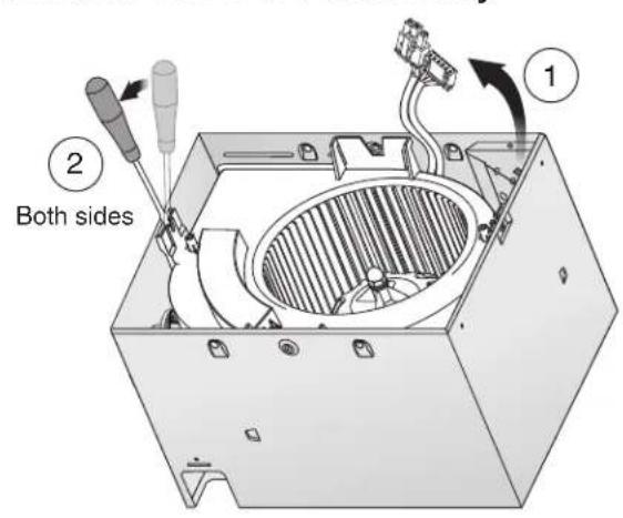
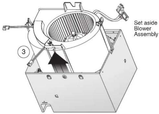
5 Remove Blower Assembly
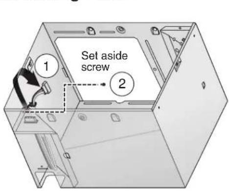
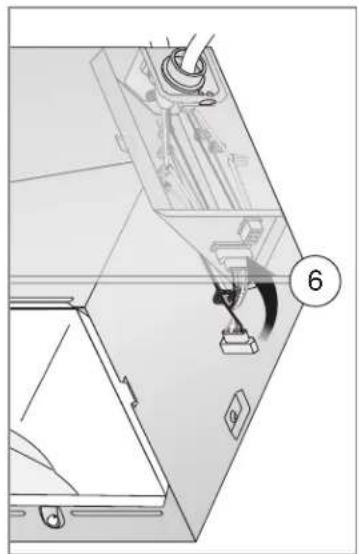
6 Remove Wiring Panel
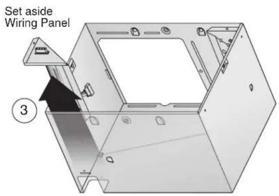
7 Insert Mounting Frame
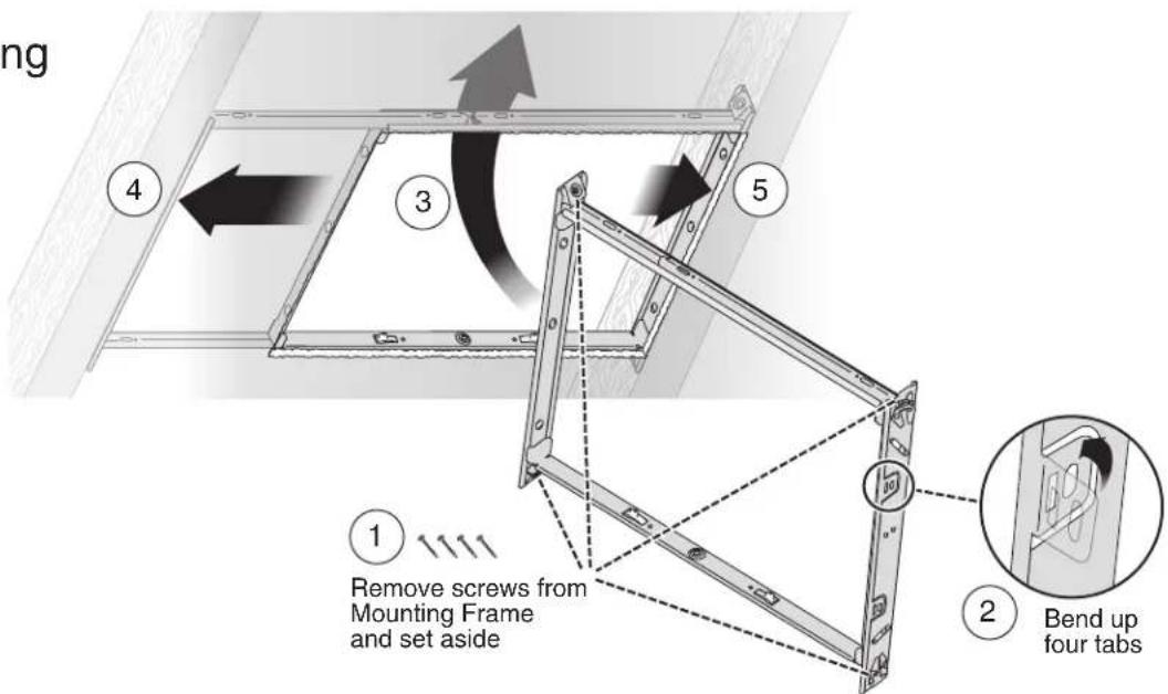
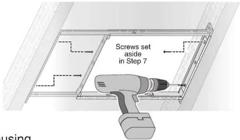
Retrofit Installation
8 Secure Mounting Frame
9 Snap-in Housing
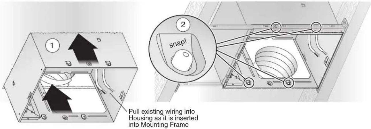
10 Attach Ducting and Duct Connector
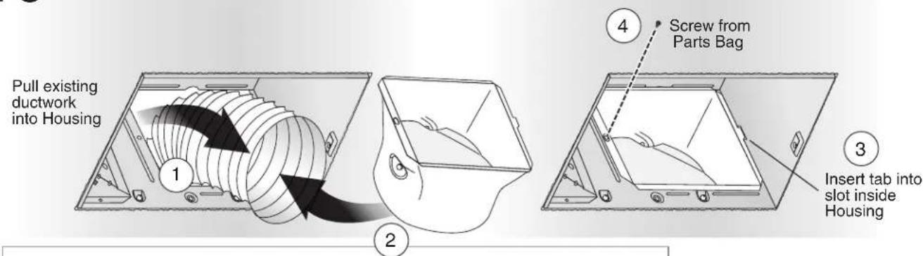
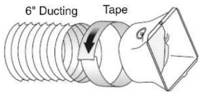
Retrofit Installation
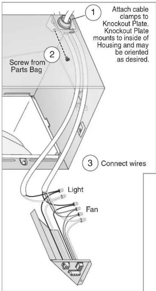
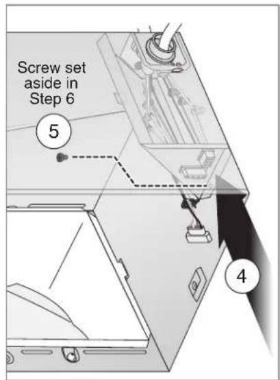
11 Install Knockout Plate, Connect Wires and Reinstall Wiring Panel
- Use proper UL-approved connectors to secure wiring to the Knockout Plate provided in Parts Bag.
- Connect wires as shown in wiring diagram.
• See OPERATION section on page 12 for details.
- SENSOR/CONTROL switch allows humidity control to be turned on for automatic operation and off for fan cleaning and maintenance purposes.
- Toggle mode can be used to manually turn fan on.
- SENSOR/CONTROL switch may be located where it is not easily accessed for everyday usage; it may need to be labeled and located where it can't be turned on without being seen from fan to comply with local and national codes.
natural_image
Technical line drawing of a mechanical assembly with a numbered component (6), no visible text or symbols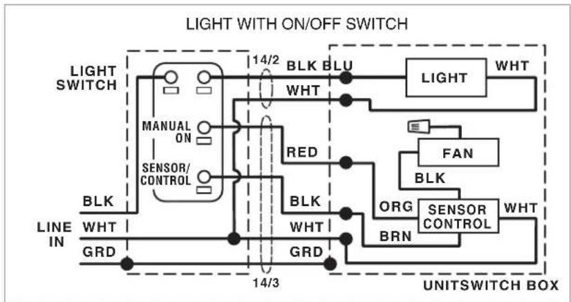
flowchart
graph TD
    A["Light SWITCH"] --> B["MANUAL ON"]
    B --> C["SENSOR/CONTROL"]
    C --> D["BLK"]
    D --> E["WHT"]
    E --> F["GRD"]
    F --> G["14/3"]
    G --> H["BRN"]
    H --> I["ORG"]
    I --> J["FAN"]
    J --> K["LED"]
    K --> L["BLK"]
    L --> M["WHT"]
    M --> N["GRD"]
    N --> O["14/2"]
    O --> P["BLK"]
    P --> Q["WHT"]
    Q --> R["GRD"]
    R --> S["14/3"]
    S --> T["BRN"]
    T --> U["FAN"]
    U --> V["LED"]
    V --> W["WHT"]
    W --> X["GRD"]
    X --> Y["14/3"]
    Y --> Z["BRN"]
    Z --> AA["FAN"]
    AA --> AB["LED"]
    AB --> AC["WHT"]
    AC --> AD["GRD"]
    AD --> AE["14/3"]
    AE --> AF["WHT"]
    AF --> AG["GRD"]
    AG --> AH["14/3"]
    AH --> AI["WHT"]
    AI --> AJ["GRD"]
    AJ --> AK["14/3"]
    AK --> AL["WHT"]
    AL --> AM["GRD"]
    AM --> AN["WHT"]
    AN --> AO["GRD"]
    AO --> AP["WHT"]
    AP --> AQ["GRD"]
    AQ --> AR["WHT"]
    AR --> AS["GRD"]
    AS --> AT["WHT"]
    AT --> AU["GRD"]
    AU --> AV["WHT"]
    AV --> AW["GRD"]
    AW --> AX["WHT"]
    AX --> AY["GRD"]
    AY --> AZ["WHT"]
    AZ --> BA["GRD"]
    BA --> BB["WHT"]
    BB --> BC["GRD"]
    BC --> BD["WHT"]
    BD --> BE["GRD"]
    BE --> BF["WHT"]
    BF --> BG["GRD"]
    BG --> BH["WHT"]
    BH --> BI["GRD"]
    BI --> BJ["WHT"]
    BJ --> BK["GRD"]
    BK --> BL["WHT"]
    BL --> BM["GRD"]
    BM --> BN["WHT"]
    BN --> BO["GRD"]
    BO --> BP["WHT"]
    BP --> BQ["GRD"]
    BQ --> BR["WHT"]
    BR --> BS["GRD"]
    BS --> BT["WHT"]
    BT --> BU["GRD"]
    BU --> BV["WHT"]
    BV --> BW["GRD"]
    BW --> BX["WHT"]
    BX --> BY["GRD"]
    BY --> BZ["WHT"]
    BZ --> CA["GRD"]
    CA --> CB["WHT"]
    CB --> CC["GRD"]
    CC --> CD["WHT"]
    CD --> CE["GRD"]
    CE --> CF["WHT"]
    CF --> CG["GRD"]
    CG --> CH["WHT"]
    CH --> CI["GRD"]
    CI --> CJ["WHT"]
    CJ --> CK["GRD"]
flowchart
graph TD
    A["MANUAL ON"] --> B["14/2"]
    C["Sensor/CONTROL"] --> D["BLK"]
    E["LINE IN"] --> F["WHT"]
    G["GRD"] --> H["14/3"]
    I["BRN"] --> J["ORG"]
    K["BRN"] --> L["FAN"]
    M["BRN"] --> N["SENSOR CONTROL"]
    O["BRN"] --> P["WHT"]
    Q["BRN"] --> R["LIGHT"]
    S["BRN"] --> T["WHT"]
    U["BRN"] --> V["FAN"]
    W["BRN"] --> X["SENSOR CONTROL"]
    Y["BRN"] --> Z["WHT"]
    AA["BRN"] --> AB["LIGHT"]
    AC["BRN"] --> AD["WHT"]
    AE["BRN"] --> AF["LIGHT"]
    AG["BRN"] --> AH["WHT"]
    AI["BRN"] --> AJ["LIGHT"]
    AK["BRN"] --> AL["WHT"]
    AM["BRN"] --> AN["LIGHT"]
    AO["BRN"] --> AP["WHT"]
    AQ["BRN"] --> AR["LIGHT"]
    AS["BRN"] --> AT["WHT"]
    AU["BRN"] --> AV["LIGHT"]
    AW["BRN"] --> AX["WHT"]
    AY["MANUAL ON"] --> AZ["14/2"]
    BA["14/2"] --> BB["BLK BLU WHT"]
    BC["14/2"] --> BD["RED BLK"]
    BE["14/2"] --> BF["WHT"]
    BG["14/2"] --> BH["BRN"]
    BI["14/2"] --> BJ["WHT"]
    BK["14/2"] --> BL["WHT"]
    BM["14/2"] --> BN["WHT"]
    BO["14/2"] --> BP["WHT"]
    BQ["14/2"] --> BR["WHT"]
    BS["14/2"] --> BT["WHT"]
    BU["14/2"] --> BV["WHT"]
    BW["MANUAL ON"] --> BX["14/2"]
    BY["14/2"] --> BZ["BLK BLU WHT"]
    CA["14/2"] --> CB["RED BLK"]
    CC["14/2"] --> CD["WHT"]
    ED["14/2"] --> DF["WHT"]
    DG["14/2"] --> DH["WHT"]
    DI["14/2"] --> DJ["WHT"]
    DK["14/2"] --> DL["WHT"]
    DM["14/2"] --> DE["WHT"]
    FD["14/2"] --> DF
    EG["14/2"] --> DF
    BH["14/2"] --> GF["WHT"]
    GH["14/2"] --> GF
    BI["14/2"] --> GF
    BJ["14/2"] --> GF
    BK["14/2"] --> GF
    BLW["14/2"] --> BF
    BNW["14/2"] --> BF
    BOW["14/2"] --> BF
    DBW["14/2"] --> BF
    DCW["14/2"] --> BF
Retrofit Installation
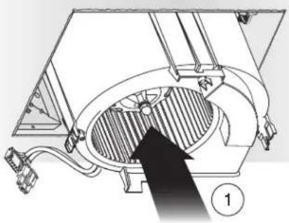
12 Reinsert and Secure Blower Assembly
CAUTION


IN ORDER TO PREVENT MOTOR/CONTROL DAMAGE:
Power must be disconnected (see page 2, WARNING item 2) before inserting motor plugs into control assembly.
natural_image
Technical diagram of a mechanical assembly with internal components and a black arrow indicating direction (no text or symbols)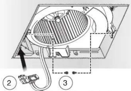
Screws from Parts Bag
If ceiling repairs are needed, place Mask in Housing after Blower Assembly is secured. See New Construction Installation Step 6. Remove Mask before installing Grille.
13 Install Grille
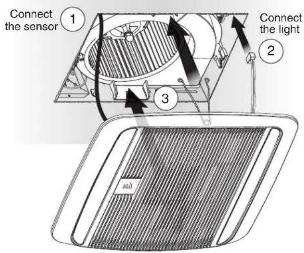
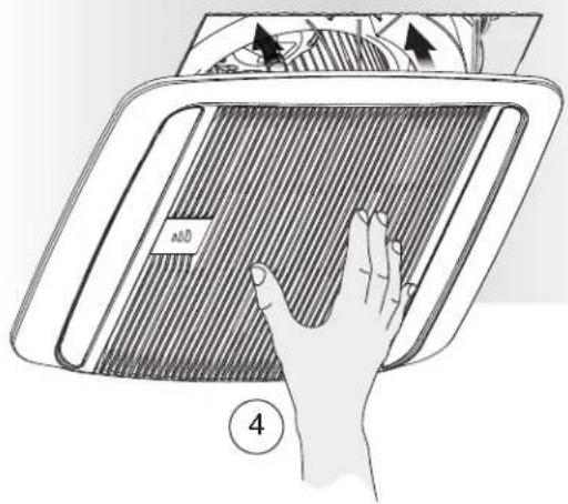
WARNING ▲ore servicing or cleaning unit, switch power off at service panel and lock the service disconnecting means to prevent power from being switched on accidentally. When the service disconnecting means cannot be locked, securely fasten a prominent warning device, such as a tag, to the service panel.
Operation
It is normal for this ventilation fan to take approximately 5 seconds to start running after it is turned on.
Modes
(For reference, wiring diagrams are on pages 5 and 10.)
Humidity sensing:
- Turn sensor/control wall switch on (make sure manual-on wall switch is off if it is installed).
- Sensor monitors humidity level for (a) moderate to rapid rise or (b) above set-point.
- Fan operates at certified airflow rate to reduce humidity.
- When humidity decreases, fan enters time delay mode. (See below.)
Manual-on (optional manual-on wall switch must be installed):
- Turn manual-on wall switch on (sensor/control wall switch can be on or off).
- Fan operates at certified airflow rate.
- Fan turns off when manual-on wall switch is turned off.
Toggle (for manual operation when optional manual-on wall switch is not installed or manually activated timed-off is desired):
- Turn sensor/control wall switch on (make sure manual-on wall switch is off if it is installed).
- Wait at least one-second.
- Turn switch off for less than one-second.
- Turn switch back on.
- Fan will operate at certified airflow rate and enter time delay mode. (See next.)
Time Delay:
Fan continues to run until user-adjustable TIME delay has passed, then fan turns off.
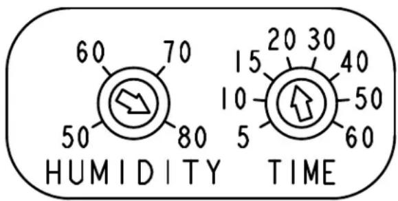
To Set User-Adjustable Humidity Sensitivity\*\*
Using a small, flat-blade screwdriver, carefully rotate HUMIDITY adjustment until arrow points to desired humidity level shown in percent relative humidity (\%RH).
To Set User-Adjustable Time Delay\*\*
Using a small, flat-blade screwdriver, carefully rotate TIME adjustment until the arrow points to the desired minutes of time delay.
** User-adjustable controls are located in corner of Fan Housing behind Grille.
Cleaning and Maintenance
CAUTION


IN ORDER TO PREVENT MOTOR/CONTROL DAMAGE:
DO NOT remove motor plug to stop spinning motor.
Power must be disconnected (see WARNING on previous page) before motor plug is removed or inserted into control assembly.
To Clean
For quiet and efficient operation, long life and attractive appearance, remove Grille and vacuum interior of unit with a dusting brush attachment.
Do not use cleaning sprays, solvents or water on, or near, the sensor.
Motor is permanently lubricated and never needs oiling. If motor is making excessive or unusual noises, replace Control Assembly and Motor.
Troubleshooting
Before continuing, turn off power as previously noted in WARNING section on previous page and CAUTION section at the top of this page.
Symptom: Fan does not run.
- Check for an open fuse or circuit breaker in the building's service panel.
- Check that the two (2) plug-in connections for the Motor and the Control are seated firmly in place.
- Check two (2) plug-in connections for Sensor and its Control are seated firmly in place.
- Check that the Blower Wheel spins freely.
Symptom: Humidity mode does not operate fan.
- Check two (2) plug-in connections for Sensor and its Control are seated firmly in place.
Symptom: The fan runs erratically.
- Check that the Blower Wheel is firmly attached to the Motor shaft and both spin freely.
Symptom: The fan seems noisy.
- Check that the back draft damper in the fan's Duct Connector pivots freely. Screws used to attach the duct to the Duct Connector may be preventing the damper from opening.
- Check that the back draft damper in the wall or roof cap pivots freely. These dampers are sometimes mistakenly painted shut or obstructed by bird and insect debris.
Service Parts
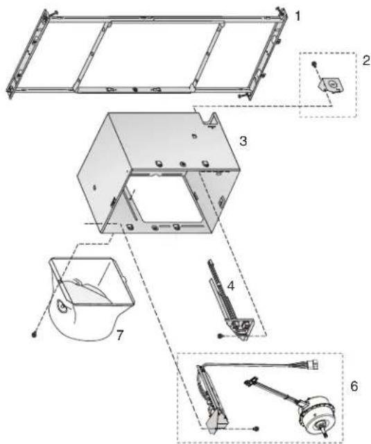
Order replacement parts by Part No., not by Key No.
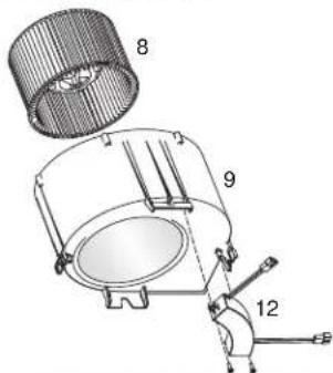
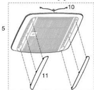
Key No. Part No. Description
1 97018349 Mounting Frame
2 97018721 Knockout Plate & Screws 3 97018382 Housing
4 97020894 Wiring Panel/Harness Assembly
5 97020952 Humidity Control Assembly & Grille Assembly (includes 10, 11)
6 1102586 Control Assembly & Motor
7 97018331 Duct Connector - 6'
8 99020301 Blower Wheel
9 97018768 Scroll Assembly
10 99140208 Grille Spring (2 req'd)
11 99111711 Lens (2 req'd)
12 99271625 LED Driver
Warranty
Broan Ventilation Fan/Lights Limited Warranty
WARRANTY PERIOD: Broan warrants to the original consumer purchaser of its Broan Ventilation Fan/Light (the "Fan") that your Fan (excluding lamps/bulbs) will be materially free from defects in materials or workmanship for a period of three (3) years from the date of original purchase. The warranty on the lamps/bulbs provided with the Fan is one (1) year and does not cover lamp/bulb breakage. This warranty does not cover accessories, such as speed controls, that may be purchased separately and installed with the Fan. The limited warranty period for replacement parts, and for Fans repaired or replaced under this limited warranty, shall continue for the remainder of the original warranty period.
NO OTHER WARRANTIES: THE FOREGOING WARRANTIES ARE EXCLUSIVE AND IN LIEU OF ANY OTHER WARRANTIES, EXPRESS OR IMPLIED. BROAN DISCLAIMS AND EXCLUDES ALL OTHER EXPRESS WARRANTIES, AND DISCLAIMS AND EXCLUDES ALL WARRANTIES IMPLIED BY LAW, INCLUDING WITHOUT LIMITATION THOSE OF MERCHANTABILITY AND FITNESS FOR A PARTICULAR PURPOSE. TO THE EXTENT THAT APPLICABLE LAW PROHIBITS THE EXCLUSION OF IMPLIED WARRANTIES, THE DURATION OF ANY APPLICABLE IMPLIED WARRANTY IS LIMITED TO THE PERIOD SPECIFIED FOR THE EXPRESS WARRANTY. Some states do not allow limitations on how long and implied warranty lasts, so the above limitation may not apply to you. Any oral or written description of the Fan is for the sole purpose of identifying it and shall not be construed as an express warranty.
REMEDY: During the applicable limited warranty period, Broan will, at its option, provide replacement parts for, or repair or replace, without charge, any Fan or part thereof, to the extent Broan finds it to be covered by and in breach of this limited warranty. Broan will ship the repaired or replaced Fan or replacement parts to you at no charge. You are responsible for all costs for removal, reinstallation and shipping, insurance or other freight charges incurred in the shipment of the Fan or part to Broan. This warranty does not cover (a) normal maintenance and service, (b) normal wear and tear, (c) any Fans or parts which have been subject to misuse, abuse, abnormal usage, negligence, accident, improper or insufficient maintenance, storage or repair (other than repair by Broan), (d) damage caused by faulty installation, or installation or use contrary to recommendations or instructions, (e) any Fan that has been moved from its original point of installation, (f) damage caused by environmental or natural elements, (g) damage in transit, (h) natural wear of finish, (i) Fans in commercial or nonresidential use, or (j) damage caused by fire, flood or other act of God. This warranty covers only Fans sold in the United States or through U.S. distributors authorized by Broan.
EXCLUSION OF DAMAGES: BROAN'S OBLIGATION TO PROVIDE REPLACEMENT PARTS, OR REPAIR OR REPLACE, AT BROAN'S OPTION. SHALL BE YOUR SOLE AND EXCLUSIVE REMEDY UNDER THIS LIMITED WARRANTY AND BROAN'S SOLE AND EXCLUSIVE OBLIGATION. BROAN SHALL NOT BE LIABLE FOR INCIDENTAL, INDIRECT, CONSEQUENTIAL OR SPECIAL DAMAGES ARISING OUT OF OR IN CONNECTION WITH THE FAN, ITS USE OR PERFORMANCE. Incidental damages include but are not limited to such damages as loss of time and loss of use. Consequential damages include but are not limited to the cost of repairing or replacing other property which was damaged if the Fan does not work properly.
Some states do not allow the exclusion or limitation of incidental or consequential damages, so the above limitation or exclusion may not apply to you. This warranty gives you specific legal rights, and you may also have other rights, which vary from state to state.
This warranty supersedes all prior warranties and is not transferable from the original consumer purchaser.
BROAN SHALL NOT BE LIABLE TO YOU, OR TO ANYONE CLAIMING UNDER YOU, FOR ANY OTHER OBLIGATIONS OR LIABILITIES, INCLUDING, BUT NOT LIMITED TO, OBLIGATIONS OR LIABILITIES ARISING OUT OF BREACH OF CONTRACT OR WARRANTY, NEGLIGENCE OR OTHER TORT OR ANY THEORY OF STRICT LIABILITY, WITH RESPECT TO THE FAN OR BROAN'S ACTS OR OMISSIONS OR OTHERWISE.
This warranty covers only replacement or repair of defective Fans or parts thereof at Broan's main facility and does not include the cost of field service travel and living expenses.
Any assistance Broan provides to or procures for you outside the terms, limitations or exclusions of this limited warranty will not constitute a waiver of such terms, limitations or exclusions, nor will such assistance extend or revive the warranty.
Broan will not reimburse you for any expenses incurred by you in repairing or replacing any defective Fan, except for those incurred with Broan's prior written permission.
HOW TO OBTAIN WARRANTY SERVICE: To qualify for warranty service, you must (a) notify Broan at the address or telephone number stated below within seven (7) days of discovering the covered defect, (b) give the model number and part identification and (c) describe the nature of any defect in the Fan or part. At the time of requesting warranty service, you must present evidence of the original purchase date.
Broan, 926 West State Street, Hartford, WI 53027
(1-800-637-1453)
www.broan.com
If you must send the Fan or part to Broan, as instructed by Broan, you must properly pack the Fan or part—Broan is not responsible for damage in transit.
LEA Y CONSERVE ESTAS INSTRUCCIONES
natural_image
Technical line drawing of a mechanical assembly with internal components and mounting brackets (no text or symbols)natural_image
Pure mechanical assembly diagram showing interlocking parts without any text, numbers, or symbolsnatural_image
Illustration of a hand pressing down on a striped panel with arrows and a label '###' (no text or symbols on the diagram itself)natural_image
Abstract geometric diagram with interlocking 3D shapes and arrows, no text or symbols present2 Apague la unidad
ADVERTENCIA
natural_image
Technical line drawing of a mechanical assembly inside a transparent box (no text or symbols)natural_image
Technical line drawing of a mechanical assembly or device with no visible text or symbolsLUZ CON INTERRUPTOR DE ENCENDIDO / APAGADO
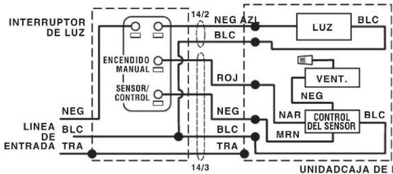
flowchart
graph TD
    A["INTERRUPTOR DE LUZ"] --> B["ENCENDIDO MANUAL"]
    B --> C["SENSOR/CONTROL"]
    C --> D["14/2 NEG AZL"]
    D --> E["BLC"]
    E --> F["LUZ"]
    F --> G["BLC"]
    H["LINEA DE ENTRADA"] --> I["BLC"]
    I --> J["TRA"]
    J --> K["14/3 NEG"]
    K --> L["BLC"]
    L --> M["TRA"]
    M --> N["NAR"]
    N --> O["MRN"]
    O --> P["CONTROL DEL SENSOR"]
    P --> Q["BLC"]
    Q --> R["VENT."]
    R --> S["NEG"]
    S --> T["ROJ"]
    T --> U["14/3 NEG"]
    U --> V["BLC"]
    V --> W["TRA"]
    W --> X["UNIDADCAJA DE I"]
NTERRUPT
natural_image
Technical diagram of a mechanical assembly with internal components and a black arrow indicating direction (no text or symbols)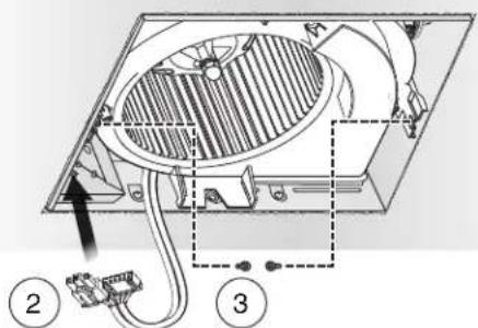
- READ AND SAVE THESE INSTRUCTIONS
- XB110HL1
- Easy installation in both new construction and retrofit
- Table of Contents
- WARNING
- TO REDUCE THE RISK OF FIRE, ELECTRIC SHOCK, OR INJURY TO PERSONS, OBSERVE THE FOLLOWING:
- CAUTION
- Typical Installation
- New Construction Installation
- Tools needed
- Materials needed
- Remove Packaging
- Install Mounting Frame
- Connect Wires and Install Knockout Plate • Run 120VAC electrical wiring to the installation location
- Insert Mask and finish Ceiling
- IN ORDER TO PREVENT
- MOTOR/CONTROL DAMAGE:
- Install Grille
- Retrofit Installation
- Switch Off Power WARNING
- Enlarge Ceiling Opening and Remove Existing Fan
- Examine Wiring Examine the existing wiring
- Install Knockout Plate, Connect Wires and Reinstall Wiring Panel
- Reinsert and Secure Blower Assembly
- IN ORDER TO PREVENT MOTOR/CONTROL DAMAGE:
- Install Grille
- Operation
- Modes
- Humidity sensing:
- Time Delay:
- To Set User-Adjustable Humidity Sensitivity\*\*
- To Set User-Adjustable Time Delay\*\*
- Cleaning and Maintenance
- To Clean
- Troubleshooting
- Symptom: Fan does not run.
- Symptom: Humidity mode does not operate fan.
- Symptom: The fan runs erratically.
- Symptom: The fan seems noisy.
- Key No. Part No. Description
- Warranty
- Broan Ventilation Fan/Lights Limited Warranty
- LEA Y CONSERVE ESTAS INSTRUCCIONES
- Apague la unidad
- ADVERTENCIA
Brand : BROAN
Model : XB110HL1
Category : Household Fan