
750 - Household Fan BROAN - Free user manual and instructions
Find the device manual for free 750 BROAN in PDF.


| Product Type | Ventilation Fan with Light |
| Brand | Broan |
| Model | 750 |
| Power Supply | 120 VAC, 60 Hz |
| Duct Size | 4 inches round |
| Maximum Insulation Value | R-40 |
| Light Socket | Max 100 W incandescent or equivalent |
| Night Light Socket | Max 7 W |
| Mounting Options | New construction (joist or hanger bars) or existing construction (cleats) |
| Housing Dimensions (pan) | 11-1/2 inches x 5-3/4 inches |
| Weight (approx.) | 8 lbs |
| Motor Lubrication | Permanently lubricated, no oiling required |
| GFCI Required | Yes, when installed over tub or shower |
| Not for Use in Kitchens | Yes |
| Wiring Requirements | Use wire suitable for 90°C; three separate wall switches for fan, light, night light |
| Grounding | Must be grounded |
| Cleaning | Grille and lens with mild soap and water; do not immerse wood-framed assemblies |
| Replacement Parts Available | Yes, see service parts list |
| Warranty | 1 year limited from date of purchase |
Frequently Asked Questions - 750 BROAN
User questions about 750 BROAN
0 question about this device. Answer the ones you know or ask your own.
Ask a new question about this device
Download the instructions for your Household Fan in PDF format for free! Find your manual 750 - BROAN and take your electronic device back in hand. On this page are published all the documents necessary for the use of your device. 750 by BROAN.
USER MANUAL 750 BROAN
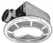
VENTILATION FAN WITH LIGHT
natural_image
Technical illustration of a ceiling fan with ventilation grilles (no text or symbols)READ AND SAVE THESE INSTRUCTIONS
WARNING


TO REDUCE THE RISK OF FIRE, ELECTRIC SHOCK, OR INJURY TO PERSONS, OBSERVE THE FOLLOWING:
- Use this unit only in the manner intended by the manufacturer. If you have questions, contact the manufacturer at the address or telephone number listed in the warranty.
- Before servicing or cleaning unit, switch power off at service panel and lock the service disconnecting means to prevent power from being switched on accidentally. When the service disconnecting means cannot be locked, securely fasten a prominent warning device, such as a tag, to the service panel.
- Installation work and electrical wiring must be done by a qualified person(s) in accordance with all applicable codes and standards, including fire-rated construction codes and standards.
- Sufficient air is needed for proper combustion and exhausting of gases through the flue (chimney) of fuel burning equipment to prevent backdrafting. Follow the heating equipment manufacturer's guideline and safety standards such as those published by the National Fire Protection Association (NFPA), and the American Society for Heating, Refrigeration and Air Conditioning Engineers (ASHRAE), and the local code authorities.
- When cutting or drilling into wall or ceiling, do not damage electrical wiring and other hidden utilities.
- Ducted fans must always be vented to the outdoors.
- If this unit is to be installed over a tub or shower, it must be marked as appropriate for the application and be connected to a GFCI (Ground Fault Circuit Interrupter) - protected branch circuit.
- Never place a switch where it can be reached from a tub or shower.
- To reduce the risk of electrical shock, do not use this fan with any solid-state speed control.
- Not for use in kitchens.
- Do not install in a ceiling insulated to a value greater than R-40.
- This unit must be grounded.
CAUTION

- For general ventilating use only. Do not use to exhaust hazardous or explosive materials and vapors.
- To avoid motor bearing damage and noisy and/or unbalanced impellers, keep drywall spray, construction dust, etc. off power unit.
- Please read specification label on product for further information and requirements.
FOR BEST RESULTS
When installing the Exhaust Fan/Light in a new construction site, install housing during the rough-in construction of the building. The blower unit, reflector and grille should be installed after the finished ceiling is in place.
PLANNING DUCTWORK AND WIRING
DUCTWORK
- Use 4" round duct.
- Plan duct run from discharge opening of fan to the outside. For best fan performance, make duct run as short as possible and use minimum number of elbows.
- Use optional Broan ducting accessories as needed.
WIRING
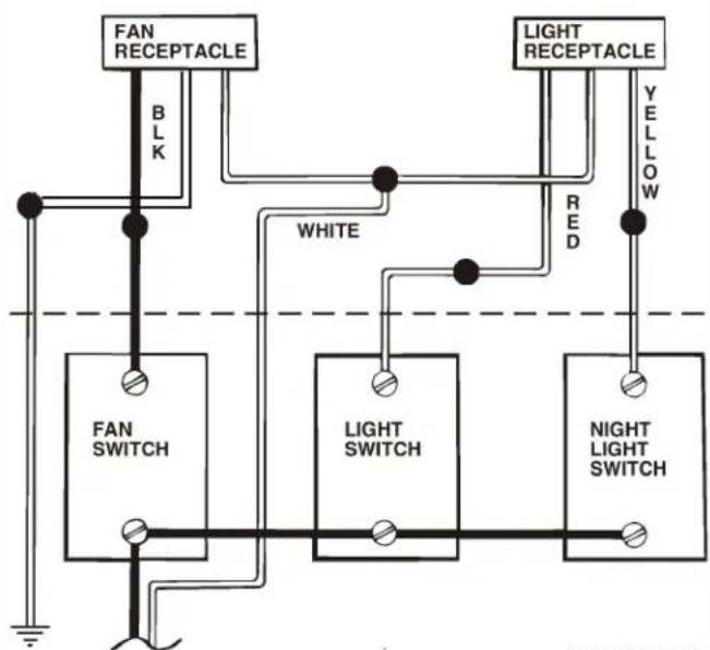
Plan to run 120 VAC house wiring (with ground) from power source, through wall switch, to junction box in housing. For separate control of fan, light, night light, three wall switches are required and five conductors are needed between the wall switch box and the fan's junction box.
IMPORTANT: Use wire suitable for 90°C.
INSTALLATION IN A NEW CONSTRUCTION SITE
PREPARATION
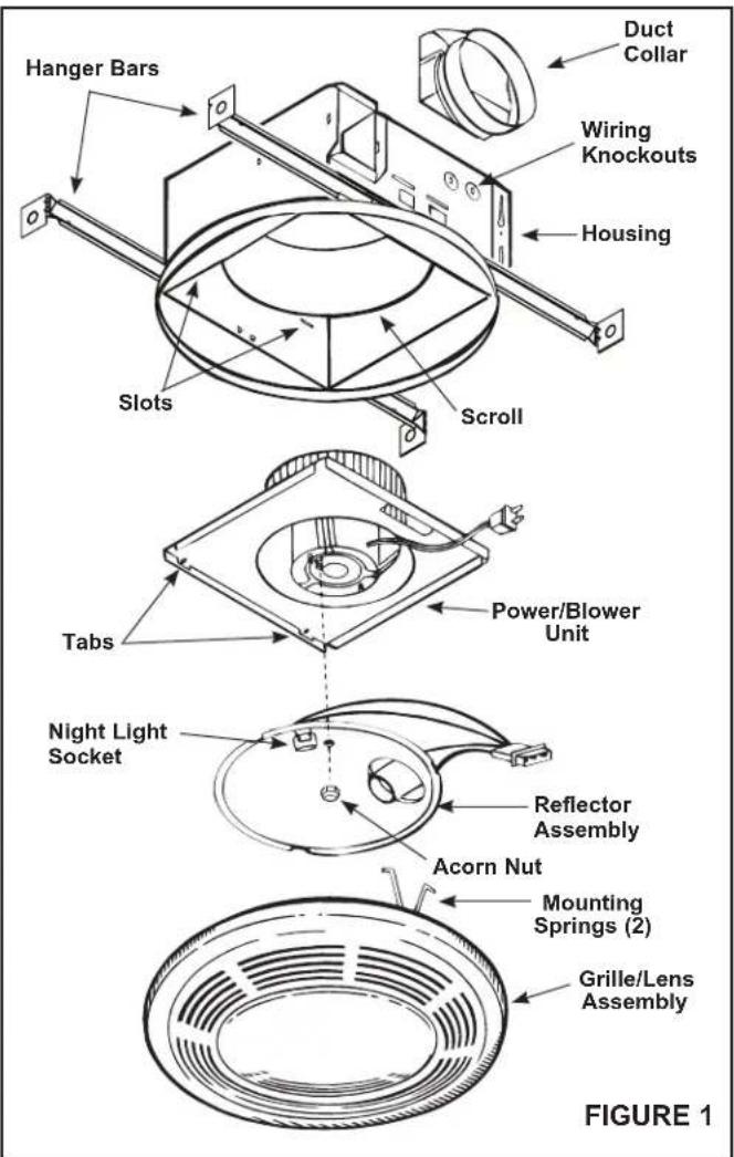
- Refer to Figure 1. Remove power unit/blower assembly from housing.
A. Unplug power unit.
B. Remove screw (located next to plug-in receptacle) which holds power/blower unit mounting plate in place. Save screw.
C. Lift mounting plate at end near the plug-in receptacle until blower wheel clears the scroll.
D. Remove plate by pulling its tabs out of slots in housing. Set power/blower unit aside until needed.
MOUNTING THE HOUSING
MOUNTING USING MOUNTING TABS
Refer to Figure 2.
- Locate fan housing next to ceiling joist.
- Use wood screws (not provided) to loosely attach housing to ceiling joist through the keyhole slots in mounting tabs.
- Adjust housing so that it will be flush with finished ceiling. For the grille to fit properly, the housing's rim must not extend beyond finished ceiling surface.
- When housing is properly adjusted, tighten screws in slots.
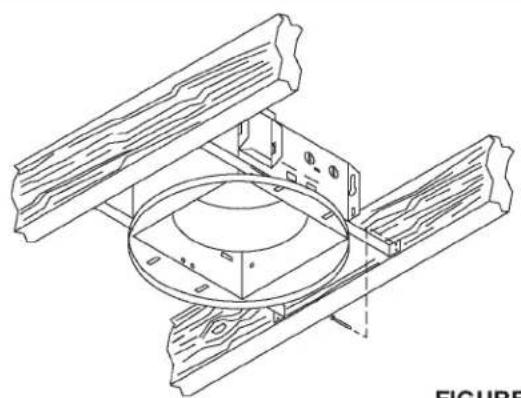
MOUNTING USING HANGER BARS
Refer to Figure 3.
- Insert hanger bars in slots provided in housing.
- Locate fan housing between joists so that the bottom of the housing is even with the planned finished ceiling. Extend the hanger bars to the joists.
- Use screws or nails (not provided) to secure hanger bars to ceiling joists.
INSTALLING DUCTWORK
- Refer to Figure 2. Place duct collar over flanges at discharge opening of fan. Secure collar by snapping tabs into slots in flanges.
- Run 4" round duct from fan's discharge opening to the outside and terminate.
- Connect duct to fan's duct collar.
WIRING
All wiring must comply with local codes and unit must be properly grounded.
- Run 120vAC house wiring (with ground) from wall switches to fan location. See Figure 4.
- Insert and secure an approved box connector into wiring entrance hole.
- Pull wires through box connector and into junction box. Tighten box connector.
- Refer to Figure 4. Connect white wires from the fan and light receptacles to white (neutral) wire from the supply. Connect black wire to wire from fan switch. Connect red wire to wire from light switch. Connect yellow wire to wire from night light switch.
- Connect the green (or bare) ground wire to the green ground lead.
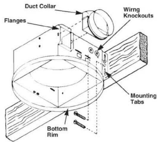
FIGURE 2
natural_image
Technical line drawing of a mechanical assembly with no visible text or symbolsFIGURE 3
flowchart
graph TD
    A["FAN RECEPTACLE"] -->|BLK| B["FAN SWITCH"]
    A -->|WHITE| C["LIGHT SWITCH"]
    A -->|RED| D["NIGHT LIGHT SWITCH"]
    E["LIGHT RECEPTACLE"] -->|YELLOW| D
    style A fill:#f9f,stroke:#333
    style B fill:#ccf,stroke:#333
    style C fill:#cfc,stroke:#333
    style D fill:#fcc,stroke:#333
120 VAC
FIGURE 4
POWER/BLOWER UNIT INSTALLATION
- Refer to Figure 1. Place power/blower unit into housing so that mounting plate's tabs insert into slots in housing.
- Press other end of mounting plate down until it is firmly seated over scroll and plug-in receptacles.
- Secure mounting plate to housing with provided screw.
- Insert motor plug into junction box receptacle.
COMPLETING INSTALLATION
- Insert lamp plug into junction box receptacle and secure reflector assembly to motor frame with wing nut provided.
- Insert lamp (100 watt maximum for light - 7 watt maximum for night light) into the socket.
NOTE: Lamp must be purchased separately. - Insert the grille assembly's mounting springs into the slots on both sides of the housing by squeezing the springs together.
- Press grille assembly firmly into place against the ceiling.
INSTALLATION IN EXISTING CONSTRUCTION
PLANNING
Review "INSTALLATION IN A NEW CONSTRUCTION SITE" and follow all instructions which apply to your installation.
LOCATION: Locate fan between ceiling joists.
WIRING AND DUCTING: Plan ducting and wiring BEFORE proceeding with installation.
CAUTION: Check area above planned location to be sure that:
- Ducting can be installed or that area is sufficient for proper venting.
- Wiring can be run to the planned location.
- No wiring or other obstruction might interfere with installation.
INSTALLATION
- The fan must be mounted between ceiling joists. Decide where you want to locate the fan, and then determine where the nearest joists are.
-
Locate the joists. Drill a starter hole in the ceiling between the joists.
-
To exactly locate the edge of joist, saw a line from hole to joist.
-
Refer to page 1. Remove power/blower unit from housing.
-
Use the housing pan as a template to mark cutout: place pan centered between joist and trace around pan.
-
Make cutout along outside of marked line.
-
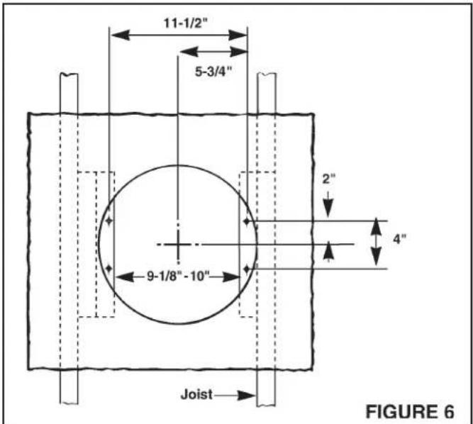
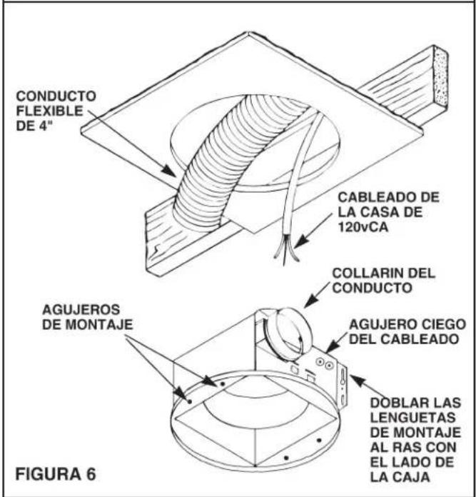
Refer to Figure 6. Install 2 x 4 cleats to both ceiling joists. In some cases it may be necessary to use more than a single cleat on one side. The distance between cleats must be at least 9 1/8" but not more than 10".
-
Remove side wiring knockout and insert and secure an approved box connector into the wiring entrance hole.
-
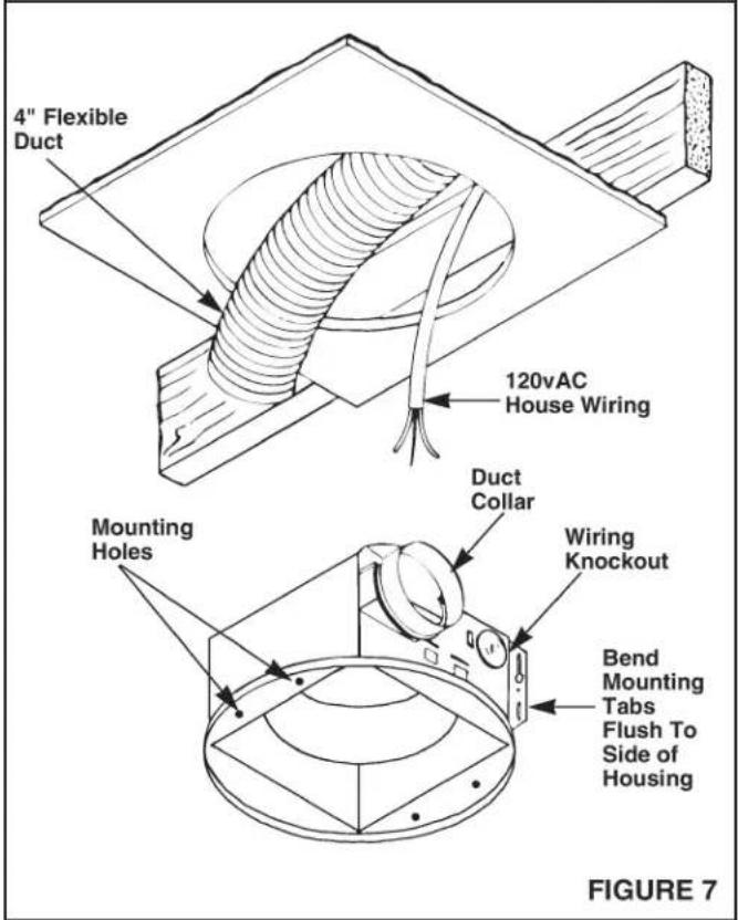
Use pliers to bend both mounting tabs as flush as possible to the side of the housing.
-
Install duct collar.
-
String wiring through box connector and connect 4" flexible duct to duct collar.
-
Carefully push ductwork and wiring back into cutout. Place housing into cutout.
-
Use wood screws to secure housing to cleats through four holes in housing's pan. make sure pan is flush to finished ceiling.
-
Install Power/Blower Unit and complete installation.
USE AND CARE USE AND CARE
WARNING: DISCONNECT ELECTRICAL POWER SUPPLY AND LOCK OUT SERVICE PANEL BEFORE RELAMPING, CLEANING, OR SERVICING THIS UNIT.
RELAMPING
Pull grille assembly away from ceiling.
Squeeze the grille assembly's mounting springs together, and remove grille assembly from housing to expose socket for relamping.
Insert lamp (100 watt maximum for light - 7 watt maximum for night light) into the socket. NOTE: Lamp must be purchased separately.
Replace grille assembly flat against the ceiling after relamping.
CLEANING
Pull grille assembly away from ceiling.
Squeeze the grille assembly's mounting springs together, and remove grille assembly from housing for cleaning.
Clean grille and lens assembly using a mild soap and water solution. Assemblies with wood frames should not be immersed.
Replace grille assembly flat against the ceiling after cleaning.
MOTOR LUBRICATION
The motor is permanently lubricated. Do not oil or disassemble motor.
SERVICE PARTS
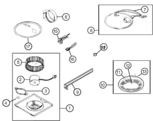
| KEY | PART NO. | DESCRIPTION |
| 1 970 | 17703 Power | Unit Assembly |
| 2 100599-000 | Motor | |
| 3 32 | 787-000 Motor | Isolation Mount |
| 4 | 32788-000 | Ground Clip |
| 5 | 100603-000 Blower Wheel | |
| 6 859 | 74-000 Reflector Assembly | |
| 7 | 85950-000 Lamp Socket Assembly | |
| 8 101 | 183-000 Duct Adapter Assembly | |
| 9 | 44388-000 Hanger Bar | |
| 10 | 97017702 | Grille & Lens Assembly |
| 11 | 99111406 | Grille |
| 12 | 61753-000 | Lens |
| 13 | 0444A-000 | Grille Spring (2 req.) |
| 14 | 99260575 | Acorn Nut |
| 15 | 99271654 | Fan Receptacle |
| 16 | 36892-000 | Light Receptacle |
| 17 | 101049-000 | Reflector |
* Not shown assembled.
Order replacement parts by "PART NO." - not by "KEY NO."
Limited Warranty
Warranty Period and Exclusions: Broan-NuTone LLC (the "Company") warrants to the original consumer purchaser of its product ("you") that the product (the "Product") will be free from material defects in the Product or its workmanship for a period of one (1) year from the date of original purchase.
The limited warranty period for any replacement parts provided by the Company and for any Products repaired or replaced under this limited warranty shall be the remainder of the original warranty period.
This warranty does not cover speed controls, fluorescent lamp starters, tubes, halogen and incandescent bulbs, fuses, filters, ducts, roof caps, wall caps and other accessories for ducting that may be purchased separately and installed with the Product. This warranty also does not cover (a) normal maintenance and service, (b) normal wear and tear, (c) any Products or parts which have been subject to misuse, abuse, abnormal usage, negligence, accident, improper or insufficient maintenance, storage or repair (other than repair by the Company), (d) damage caused by faulty installation, or installation or use contrary to recommendations or instructions, (e) any Product that has been moved from its original point of installation, (f) damage caused by environmental or natural elements, (g) damage in transit, (h) natural wear of finish, (i) Products in commercial or nonresidential use, or (j) damage caused by fire, flood or other act of God. This warranty covers only Products sold to original consumers in the United States by the Company or U.S. distributors authorized by the Company.
This warranty supersedes all prior warranties and is not transferable from the original consumer purchaser.
No Other Warranties: This Limited Warranty contains the Company's sole obligation and your sole remedy for defective products. The foregoing warranties are exclusive and in lieu of any other warranties, express or implied. THE COMPANY DISCLAIMS AND EXCLUDES ALL OTHER EXPRESS WARRANTIES, AND DISCLAIMS AND EXCLUDES ALL WARRANTIES IMPLIED BY LAW, INCLUDING WITHOUT LIMITATION THOSE OF MERCHANTABILITY AND FITNESS FOR A PARTICULAR PURPOSE. To the extent that applicable law prohibits the exclusion of implied warranties, the duration of any applicable implied warranty is limited to the period specified for the express warranty above. Some states do not allow limitations on how long an implied warranty lasts, so the above limitation may not apply to you. Any oral or written description of the Product is for the sole purpose of identifying it and shall not be construed as an express warranty. Whenever possible, each provision of this Limited Warranty shall be interpreted in such manner as to be effective and valid under applicable law, but if any provision is held to be prohibited or invalid, such provision shall be ineffective only to the extent of such prohibition or invalidity, without invalidating the remainder of such provision or the other remaining provisions of the Limited Warranty.
Remedy: During the applicable limited warranty period, the Company will, at its option, provide replacement parts for, or repair or replace, without charge, any Product or part thereof, to the extent the Company finds it to be covered by and in breach of this limited warranty under normal use and service. The Company will ship the repaired or replaced Product or replacement parts to you at no charge. You are responsible for all costs for removal, reinstallation and shipping, insurance or other freight charges incurred in the shipment of the Product or part to the Company. If you must send the Product or part to the Company, as instructed by the Company, you must properly pack the Product or part—the Company is not responsible for damage in transit. The Company reserves the right to utilize reconditioned, refurbished, repaired or remanufactured Products or parts in the warranty repair or replacement process. Such Products and parts will be comparable in function and performance to an original Product or part and warranted for the remainder of the original warranty period.
Exclusion of Damages: THE COMPANY'S OBLIGATION TO PROVIDE REPLACEMENT PARTS, OR REPAIR OR REPLACE, AT THE COMPANY'S OPTION, SHALL BE YOUR SOLE AND EXCLUSIVE REMEDY UNDER THIS LIMITED WARRANTY AND THE COMPANY'S SOLE AND EXCLUSIVE OBLIGATION. THE COMPANY SHALL NOT BE LIABLE FOR INCIDENTAL, INDIRECT, CONSEQUENTIAL OR SPECIAL DAMAGES ARISING OUT OF OR IN CONNECTION WITH THE PRODUCT, ITS USE OR PERFORMANCE.
Some states do not allow the exclusion or limitation of incidental or consequential damages, so the above limitation or exclusion may not apply to you. This warranty gives you specific legal rights, and you may also have other rights, which vary from state to state.
This warranty covers only replacement or repair of defective Products or parts thereof at the Company's main facility and does not include the cost of field service travel and living expenses.
Any assistance the Company provides to or procures for you outside the terms, limitations or exclusions of this limited warranty will not constitute a waiver of such terms, limitations or exclusions, nor will such assistance extend or revive the warranty.
The Company will not reimburse you for any expenses incurred by you in repairing or replacing any defective Product, except for those incurred with the Company's prior written permission.
How to Obtain Warranty Service: To qualify for warranty service, you must (a) notify the Company at the address or telephone number stated below within seven (7) days of discovering the covered defect, (b) give the model number and part identification and (c) describe the nature of any defect in the Product or part. At the time of requesting warranty service, you must present evidence of the original purchase date. If you cannot provide a copy of the original written limited warranty, then the terms of the Company's most current written limited warranty for your particular product will control. The most current limited written warranties for the Company's products can be found at www.broan.com.
Broan 926 West State Street, Hartford, WI 53027 www.broan.com 800-637-1453
natural_image
Technical illustration of a mechanical component with concentric rings and a protruding rod (no text or symbols)Página 5
LEA Y CONSERVE ESTAS INSTRUCCIONES
ADVERTENCIA


PARA REDUCIR EL RIESGO DE INCENDIO, CHOQUE ELECTRICO, O LESION A PERSONAS, PROCURE LO SIGUIENTE:
natural_image
Technical line drawing of a mechanical assembly with wooden components and a central circular component (no text or symbols)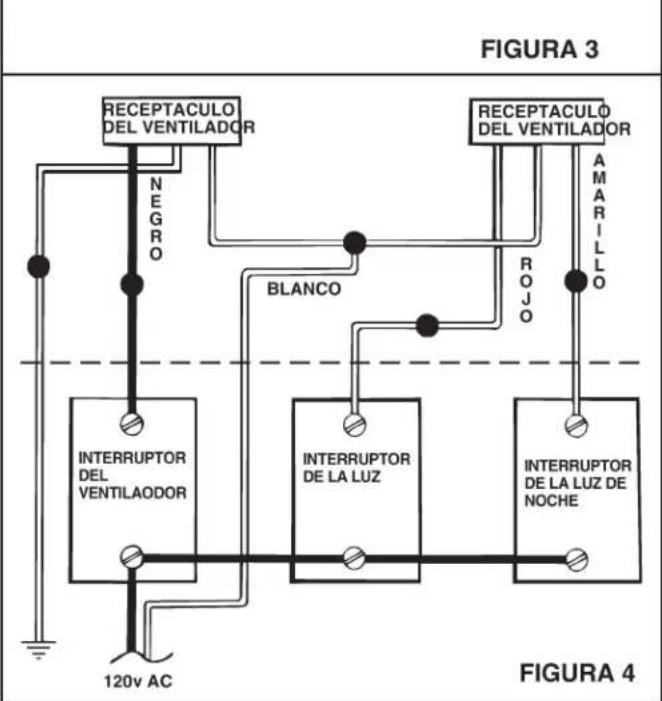
flowchart
graph TD
    A["RECEPTACULO DEL VENTILADOR"] -->|NEGRO| B["INTERRUPTOR DEL VENTILAODOR"]
    A -->|BLANCO| C["INTERRUPTOR DE LA LUZ"]
    A -->|ROJO| D["INTERRUPTOR DE LA LUZ DE NOCHE"]
    E["RECEPTACULO DEL VENTILADOR"] -->|AMARILLO| F["120V AC"]
    style A fill:#f9f,stroke:#333
    style B fill:#ccf,stroke:#333
    style C fill:#cfc,stroke:#333
    style D fill:#fcc,stroke:#333
- VENTILATION FAN WITH LIGHT
- READ AND SAVE THESE INSTRUCTIONS
- WARNING
- TO REDUCE THE RISK OF FIRE, ELECTRIC SHOCK, OR INJURY TO PERSONS, OBSERVE THE FOLLOWING:
- CAUTION
- FOR BEST RESULTS
- PLANNING DUCTWORK AND WIRING
- DUCTWORK
- WIRING
- INSTALLATION IN A NEW CONSTRUCTION SITE
- PREPARATION
- MOUNTING THE HOUSING
- MOUNTING USING MOUNTING TABS
- Refer to Figure 2.
- MOUNTING USING HANGER BARS
- Refer to Figure 3.
- INSTALLING DUCTWORK
- POWER/BLOWER UNIT INSTALLATION
- COMPLETING INSTALLATION
- INSTALLATION IN EXISTING CONSTRUCTION
- PLANNING
- INSTALLATION
- USE AND CARE USE AND CARE
- RELAMPING
- CLEANING
- MOTOR LUBRICATION
- Limited Warranty
- LEA Y CONSERVE ESTAS INSTRUCCIONES
- ADVERTENCIA
- PARA REDUCIR EL RIESGO DE INCENDIO, CHOQUE ELECTRICO, O LESION A PERSONAS, PROCURE LO SIGUIENTE:
Brand : BROAN
Model : 750
Category : Household Fan