
696 - Household Fan BROAN - Free user manual and instructions
Find the device manual for free 696 BROAN in PDF.


| Product Type | Ceiling-Mounted Exhaust Fan with Light |
| Brand | Broan |
| Model | 696 |
| Mounting | Ceiling only; fits up to 12/12 roof pitch |
| Duct Size | 4 inches round |
| Light Compatibility | Maximum 100W incandescent bulb; includes light lens and reflector |
| Electrical Rating | 120V, 60Hz (typical US household); must be grounded |
| Airflow (Estimated) | Approximately 70-90 CFM |
| Sound Level (Estimated) | Around 3-4 sones |
| Construction | Metal housing with adjustable mounting brackets |
| Damper | Integral backdraft damper included |
| Motor | Permanently lubricated; never needs oiling |
| Safety Features | Grounding required; must vent to outside; thermal overload protection (assumed) |
| Cleaning | Plastic parts with mild soap and water; vacuum motor and housing |
| Bulb Replacement | Easy access via snap-off lens; use up to 100W only |
| Warranty | Refer to Broan website; typical 1-3 years |
| Certifications | Complies with local/national electrical codes; UL listed (assumed) |
Frequently Asked Questions - 696 BROAN
User questions about 696 BROAN
0 question about this device. Answer the ones you know or ask your own.
Ask a new question about this device
Download the instructions for your Household Fan in PDF format for free! Find your manual 696 - BROAN and take your electronic device back in hand. On this page are published all the documents necessary for the use of your device. 696 by BROAN.
USER MANUAL 696 BROAN
READ AND SAVE THESE INSTRUCTIONS
SAFETY NOTES
- ALL ELECTRICAL WORK MUST BE DONE IN ACCORDANCE WITH LOCAL AND/OR NATIONAL ELECTRICAL CODE AS APPLICABLE. FOR SAFETY, THIS PRODUCT MUST BE GROUNDED. IF YOU ARE UNFAMILIAR WITH METHODS OF INSTALLING ELECTRICAL WIRING, SECURE THE SERVICES OF A QUALIFIED ELECTRICIAN.
- TURN OFF POWER AT SERVICE ENTRANCE BEFORE INSTALLING, WIRING OR SERVICING THIS PRODUCT.
- This product is designed for ceiling installation only. This product is designed for installation in ceilings up to a 12/12 pitch. Ductwork must point up. DO NOT MOUNT THIS PRODUCT IN A WALL.
- CAUTION: Always vent this product to the outside - NOT into spaces within walls or ceilings, attics, crawl spaces, garages, etc.
- To avoid motor bearing damage and noisy and/or unbalanced impellers, keep drywall spray, construction dust, etc. off power unit.
- Fireplaces, gas furnaces, water heaters and the like, require proper flow of combustion air and exhaust. To prevent this flow from being altered by an exhaust fan, follow the heating equipment manufacturer's guidelines and see safety standards such as those published by NFPA and ASHRAE. Please direct any remaining questions to the Broan Engineering Department.
- Please read specification label on product for further information and requirements.
TOOLS AND MATERIALS REQUIRED
• Straight-blade & Phillips screwdrivers
- Saber or keyhole saw
- Hammer
• 4" round duct and elbows (as needed)
- Roof or wall cap
- Duct tape
• Electrical supplies (to comply with codes)
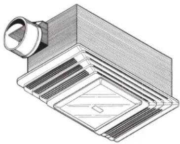
natural_image
Technical illustration of a mechanical component with layered structure and mounting bracket (no text or symbols)For Warranty Statement, Service Parts, Technical Support, or to Register your product, please visit our website or call:
In the United States -
Broan.com
800-637-1453 or
NuTone.com
888-336-6151
In Canada -
Broan.ca or
NuTone.ca
877-896-1119
- Unplug the fan assembly from the BLACK receptacle. Remove the plastic bag and set it aside.
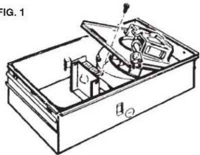
- Remove the mounting screw and carefully lift the fan assembly out of the housing. (FIG. 1)
- Refer to the wiring diagram of you unit on the next page. Remove appropriate knockout(s) by inserting a screwdriver blade into slot(s) and bending it back and forth to break tabs. (FIG. 2)
- Insert the adjustable mounting brackets into the bracket channels on the housing. (FIG. 3)
INSTALL THE FAN
- Choose the location for your fan. For best possible performance, use the shortest possible duct run and a minimum number of elbows.
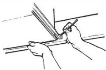
- Position unit between joists and extend mounting brackets. Position brackets such that bottom edge of housing will be flush with finished ceiling. Mark the top of keyhole slot on all four mounting brackets. (FIG. 4)
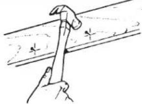
- Remove unit temporarily, and pound nails partially into joists at all four marked locations. (FIG. 5)
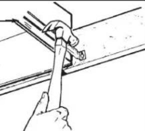
- Hang unit from nails and use embossed measuring guides to check if unit will be flush with finished ceiling. Pound nails tight. For wide joist centers: A #8 x 3/8 self-tapping screw can be used to join extended brackets together and create a rigid mount. To ensure a noise-free mount, crimp the bracket channels tightly around mounting brackets. (FIG. 6)
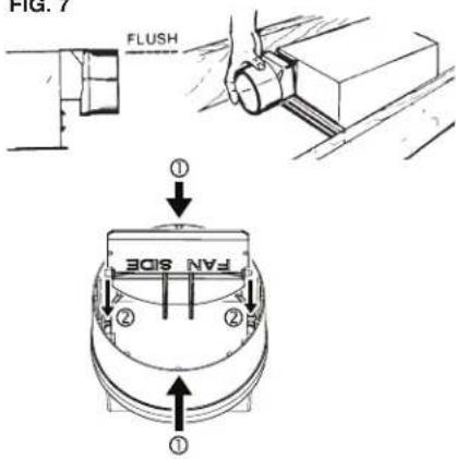
- Snap the damper/duct connector onto housing. Make sure that tabs on the connector lock in housing slots. (Top of damper/duct connector will be flush with top of housing). (FIG. 7)
NOTE: Make sure damper flap is in place inside of duct connector. If it is not: ① Squeeze top and bottom of connector to ② snap flap back into place. - Wire unit using appropriate diagram.
- Replace fan assembly removed in STEP 2 and plug it into BLACK receptacle.
CAUTION
To avoid the possibility of overheating and/or fire, the grille must be installed as shown in FIG. 8. Acorn nut and tooth washer must attach to threaded rod through proper hole in light reflector.
- Slide the light reflector into opening in grille and plug into WHITE receptacle. Use acorn nut and tooth washer from plastic bag to attach grille reflector assembly to threaded rod on housing. Tighten securely using pliers or nut driver. Install a light bulb - 100 watt maximum. (FIG. 8)
- Install light lens by (1) hooking one of its tabs into notch in grille/reflector assembly; (2) apply light pressure to other tab with fingertips and (3) snap into place. (FIG. 9)
FIG. 1
natural_image
Technical line drawing of an open mechanical device with internal components (no text or symbols)FIG. 2
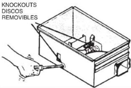
FIG. 3
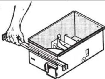
natural_image
Illustration of a hand using a tool to adjust or install an open electrical box (no text or symbols visible)FIG. 4
natural_image
Line drawing of hands using a tool to cut or mark a metal strip (no text or symbols)TO REPLACE BULB - Remove lens by gently depressing sides and pull down. Use bulb rated up to 100 watts only.
TO CLEAN LENS AND GRILLE - Remove lens as explained above. Remove bulb. Remove screw in center of reflector and lower assembly.
CAUTION: Grille and reflector are separate units. Unplug light from white receptacle. Plastic parts can be cleaned with mild, soapy water and dried with soft cloth. DO NOT USE ABRASIVE CLOTHS, STEEL WOOL PADS, OR SCOURING POWDERS.
TO CLEAN FAN ASSEMBLY - Unplug fan motor cord from black receptacle. Remove retaining screw located near receptacle. See STEP 2.
CAUTION: Fan and motor will swing downward when screw is removed. Support this unit with free hand while removing retaining screw.
Gently vacuum fan, motor and interior of housing. Motor is permanently lubricated - never needs oiling.
METAL AND ELECTRICAL PARTS SHOULD NEVER BE IMMERSED IN WATER.
TO REASSEMBLE ALL ABOVE PARTS - Reverse all procedures explained above. Make sure two retention tabs are in place when reassembling fan unit. (See STEP 2). Assemblies should not be disassembled any further than explained above.
FIG. 5
natural_image
Hand holding a tool over a metal surface, no text or symbols visibleFIG. 6
EMBOSSED
MEASURING
GUIDES
GUIAS
ESTAMPADAS
DE MEDICION
natural_image
Hand using a tool to lift or install a metal bracket (no text or symbols visible)FIG. 7
USO Y MANTENIMIENTO
DESCONECTE LA FUENTE DE ENERGIA ELECTRICA ANTES DE DAR SERVICIO A ESTA UNIDAD.
Brand : BROAN
Model : 696
Category : Household Fan