MLS100 - Miter saw MAKITA - Free user manual and instructions
Find the device manual for free MLS100 MAKITA in PDF.

User questions about MLS100 MAKITA
0 question about this device. Answer the ones you know or ask your own.
Ask a new question about this device
Download the instructions for your Miter saw in PDF format for free! Find your manual MLS100 - MAKITA and take your electronic device back in hand. On this page are published all the documents necessary for the use of your device. MLS100 by MAKITA.
USER MANUAL MLS100 MAKITA
DOUBLE INSULATION DOUBLE ISOLATION DOBLE AISLAMENTO
△WARNING:
For your personal safety, READ and UNDERSTAND before using. SAVE THESE INSTRUCTIONS FOR FUTURE REFERENCE.
AVERTISSEMENT:
Max. Cutting capacities (H x W) with blade 255 mm in diameter
MLS100
255 mm (10")
15.88 mm (5/8")
Left 45^ ,Right 45^
Left 45^
| Bevel angle | Miter angle | |
| 0° | 45° (left and right) | |
| 0° | 75 mm x 130 mm(2-15/16") X (5-1/8") | 75 mm x 90 mm(2-15/16") X (3-9/16") |
| 45° (left) | 48 mm x 120 mm(1-7/8") X (4-3/4") | 48 mm x 90 mm(1-7/8") X (3-9/16") |
No load speed (^-1)
Dimensions (L× W× H)
Net weight
Safety class
- Due to our continuing programme of research and development, the specifications herein are subject to change without notice.
- Note: Specifications may differ from country to country.
END217-2
Symbols
The following show the symbols used for the equipment. Be sure that you understand their meaning before use.

- Read instruction manual.

DOUBLE INSULATION

- To avoid injury from flying debris, keep holding the saw head down, after making cuts, until the blade has come to a complete stop.
- Do not place hand or fingers close to the blade.
- For your safety, remove the chips, small pieces, etc. from the table top before operation.
Always set SUB-FENCE to left position when performing left bevel cuts. Failure to do so may cause serious injury to operator.
To loosen the bolt, turn it clockwise.


Only for EU countries
Do not dispose of electric equipmenttogether with household waste material!In observance of European Directive2002/96/EC on waste electric andelectronic equipment and itsimplementation in accordance with
national law, electric equipment that have reached the end of their life must be collected separately and returned to an environmentally compatible recycling facility.
ENE004-1
Intended use
The tool is intended for accurate straight and miter cutting in wood. With appropriate saw blades, aluminum can also be sawed.
ENF002-1
Power supply
The tool should be connected only to a power supply of the same voltage as indicated on the nameplate, and can only be operated on single-phase AC supply. They are double-insulated in accordance with European Standard and can, therefore, also be used from sockets without earth wire.
ENA001-2
SAFETY INSTRUCTIONS
WARNING! When using electric tools, basic safety precautions, including the following, should always be followed to reduce the risk of fire, electric shock and personal injury. Read all these instructions before operating this product and save these instructions.
For safe operations:
- Keep work area clean.
Cluttered areas and benches invite injuries.
- Consider work area environment.
Do not expose power tools to rain. Do not use power tools in damp or wet locations. Keep work area well lit. Do not use power tools where there is risk to cause fire or explosion.
3. Guard against electric shock.
Avoid body contact with earthed or grounded surfaces (e.g. pipes, radiators, ranges, refrigerators).
4. Keep children away.
Do not let visitors touch the tool or extension cord. All visitors should be kept away from work area.
5. Store idle tools.
When not in use, tools should be stored in a dry, high or locked up place, out of reach of children.
6. Do not force the tool.
It will do the job better and safer at the rate for which it was intended.
7. Use the right tool.
Do not force small tools or attachments to do the job of a heavy duty tool. Do not use tools for purposes not intended; for example, do not use circular saws to cut tree limbs or logs.
8. Dress properly.
Do not wear loose clothing or jewellery, they can be caught in moving parts. Rubber gloves and non-skid footwear are recommended when working outdoors. Wear protecting hair covering to contain long hair.
9. Use safety glasses and hearing protection.
Also use face or dust mask if the cutting operation is dusty.
10. Connect dust extraction equipment.
If devices are provided for the connection of dust extraction and collection facilities ensure these are connected and properly used.
11. Do not abuse the cord.
Never carry the tool by the cord or yank it to disconnect it from the socket. Keep the cord away from heat, oil and sharp edges.
12. Secure work.
Use clamps or a vice to hold the work. It is safer than using your hand and it frees both hands to operate the tool.
13. Do not overreach.
Keep proper footing and balance at all times.
14. Maintain tools with care.
Keep cutting tools sharp and clean for better and safer performance. Follow instructions for lubrication and changing accessories. Inspect tool cord periodically and if damaged have it repaired by an authorized service facility. Inspect extension cords periodically and replace, if damaged. Keep handles dry, clean and free from oil and grease.
15. Disconnect tools.
When not in use, before servicing and when
changing accessories such as blades, bits and cutters.
16. Remove adjusting keys and wrenches.
Form the habit of checking to see that keys and adjusting wrenches are removed from the tool before turning it on.
17. Avoid unintentional starting.
Do not carry a plugged-in tool with a finger on the switch. Ensure switch is off when plugging in.
18. Use outdoor extension leads.
When tool is used outdoors, use only extension cords intended for outdoor use.
19. Stay alert.
Watch what you are doing. Use common sense.
Do not operate tool when you are tired.
20. Check damaged parts.
Before further use of the tool, a guard or other part that is damaged should be carefully checked to determine that it will operate properly and perform its intended function. Check for alignment of moving parts, free running of moving parts, breakage of parts, mounting and any other conditions that may affect its operation. A guard or other part that is damaged should be properly repaired or replaced by an authorized service center unless otherwise indicated in this instruction manual. Have defective switches replaced by an authorized service facility. Do not use the tool if the switch does not turn it on and off.
21. Warning.
The use of any accessory or attachment, other than those recommended in this instruction manual or the catalog, may present a risk of personal injury.
22. Have your tool repaired by a qualified person.
This electric tool is in accordance with the relevant safety requirements. Repairs should only be carried out by qualified persons using original spare parts, otherwise this may result in considerable danger to the user.
ENB040-3
ADDITIONAL SAFETY RULES FOR TOOL
1. Wear eye protection.
- Keep hands out of path of saw blade. Avoid contact with any coasting blade. It can still cause severe injury.
- Do not operate saw without guards in place. Check blade guard for proper closing before each use. Do not operate saw if blade guard does not move freely and close instantly. Never clamp or tie the blade guard into the
open position.
- Do not perform any operation freehand. The workpiece must be secured firmly against the turn base and guide fence with the vise during all operations. Never use your hand to secure the workpiece.
- Never reach around saw blade.
- Turn off tool and wait for saw blade to stop before moving workpiece or changing settings.
- Unplug tool before changing blade or servicing.
- Do not use the tool in the presence of flammable liquids or gases.
- Check the blade carefully for cracks or damage before operation. Replace cracked or damaged blade immediately.
- Use only flanges specified for this tool.
- Be careful not to damage the arbor, flanges (especially the installing surface) or bolt. Damage to these parts could result in blade breakage.
- Make sure that the turn base is properly secured so it will not move during operation.
- For your safety, remove the chips, small pieces, etc. from the table top before operation.
- Avoid cutting nails. Inspect for and remove all nails from the workpiece before operation.
- Make sure the shaft lock is released before the switch is turned on.
- Be sure that the blade does not contact the turn base in the lowest position.
- Hold the handle firmly. Be aware that the saw moves up or down slightly during start-up and stopping.
- Make sure the blade is not contacting the workpiece before the switch is turned on.
- Before using the tool on an actual workpiece, let it run for a while. Watch for vibration or wobbling that could indicate poor installation or a poorly balanced blade.
- Wait until the blade attains full speed before cutting.
- Stop operation immediately if you notice anything abnormal.
- Do not attempt to lock the trigger in the on position.
- Be alert at all times, especially during repetitive, monotonous operations. Do not be lulled into a false sense of security. Blades are extremely unforgiving.
- Always use accessories recommended in this manual. Use of improper accessories such as abrasive wheels may cause an injury.
-
Do not use the saw to cut other than wood, aluminum or similar materials.
-
Connect miter saws to a dust collecting device when sawing.
- Select saw blades in relation to the material to be cut.
- Take care when slotting.
- Replace the kerf board when worn.
- Do not use saw blades manufactured from high speed steel.
-
Some dust created from operation contains chemicals known to cause cancer, birth defects or other reproductive harm. Some examples of these chemicals are:
-
lead from lead-based-painted material and,
arsenic and chromium from chemically-treated lumber.
Your risk from these exposures varies, depending on how often you do this type of work. To reduce your exposure to these chemicals: work in a well ventilated area and work with approved safety equipment, such as those dust masks that are specially designed to filter out microscopic particles.
- To reduce the emitted noise, always be sure that the blade is sharp and clean.
- The operator is adequately trained in the use, adjustment and operation of the machine.
- Use correctly sharpened saw blades. Observe the maximum speed marked on the saw blade.
- Refrain from removing any cut-offs or other parts of the workpiece from the cutting area whilst the tool is running and the saw head is not in the rest position.
SAVE THESE INSTRUCTIONS.
INSTALLATION
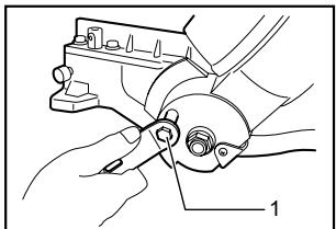
- Wrench
007766
1. Knob
007772
When the tool is shipped, the handle is locked in the lowered position by the stopper pin. Loosen the bolt with a wrench provided with the tool and move the saw head to the right angle. Remove the bolt and secure the saw head with the knob.
Installing auxiliary plate
007830
- Auxiliary plate
- Screw
- Base
Installing the auxiliary plate using the hole in the tool's base and secure it by tightening the screw.
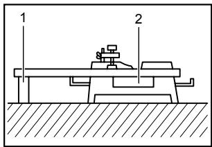
Bench mounting
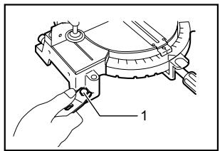
When the tool is shipped, the handle is locked in the lowered position by the stopper pin. Release the stopper pin by lowering the handle slightly and pulling the stopper pin.
1. Stopper pin
007754
This tool should be bolted with four bolts to a level and stable surface using the bolt holes provided in the tool's base. This will help prevent tipping and possible injury.
1. Bolt
007767
FUNCTIONAL DESCRIPTION
CAUTION:
Always be sure that the tool is switched off and unplugged before adjusting or checking function on the tool.
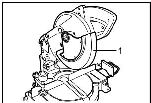
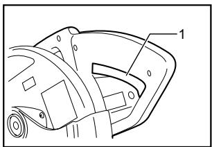
Blade guard
1. Blade guard
007755
When lowering the handle, the blade guard rises automatically. The guard is spring loaded so it returns to its original position when the cut is completed and the handle is raised. NEVER DEFEAT OR REMOVE THE BLADE GUARD OR THE SPRING WHICH ATTACHES TO THE GUARD.
In the interest of your personal safety, always maintain the blade guard in good condition. Any irregular operation of the blade guard should be corrected immediately. Check to assure spring loaded return action of guard. NEVER USE THE TOOL IF THE BLADE GUARD OR SPRING ARE DAMAGED, FAULTY OR REMOVED. DOING SO IS HIGHLY DANGEROUS AND CAN CAUSE SERIOUS PERSONAL INJURY.
If the see-through blade guard becomes dirty, or sawdust adheres to it in such a way that the blade is no longer easily visible, unplug the saw and clean the guard carefully with a damp cloth. Do not use solvents or any petroleum-based cleaners on the plastic guard.
If the see-through blade guard becomes dirty, or sawdust adheres to it in such a way that the blade and/or workpiece is no longer easily visible, unplug the saw and clean the guard carefully with a damp cloth. Do not use solvents or any petroleum-based cleaners on the plastic guard.
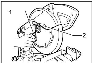
If the blade guard is especially dirty and vision through the guard is impaired, use the supplied wrench to loosen the hex bolt holding the center cover. Loosen the hex bolt by turning it counterclockwise and raise the blade guard and center cover. With the blade guard so positioned, cleaning can be more completely and efficiently accomplished. When cleaning is complete, reverse procedure above and secure bolt. Do not remove spring holding blade guard. If guard becomes discolored through age or UV light exposure, contact a Makita service center for a new guard. DO NOT DEFEAT OR REMOVE GUARD.
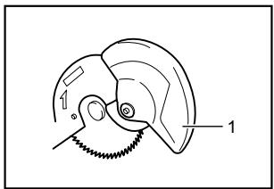
001782
1. Blade guard
Kerf board
007777
1. Kerf board
This tool is provided with the kerf board in the turn base to minimize tearing on the exit side of a cut. If the kerf groove has not yet been cut in the kerf board by the factory, you should cut the groove before actually using the tool to cut a workpiece. Switch on the tool and lower the blade gently to cut a groove in the kerf board.
Maintaining maximum cutting capacity
This tool is factory adjusted to provide the maximum cutting capacity for a 255 mm saw blade.
When installing a new blade, always check the lower limit position of the blade and if necessary, adjust it as follows:
First, unplug the tool. Lower the handle completely. Use the wrench to turn the adjusting bolt until the periphery of the blade extends slightly below the top surface of the turn base at the point where the front face of the guide fence meets the top surface of the turn base.
007832
1. Adjusting bolt
With the tool unplugged, rotate the blade by hand while holding the handle all the way down to be sure that the blade does not contact any part of the lower base. Re-adjust slightly, if necessary.
007831
- Top surface of turn base
- Periphery of blade
- Guide fence
CAUTION:
After installing a new blade, always be sure that the blade does not contact any part of the lower base when the handle is lowered completely. Always do this with the tool unplugged.
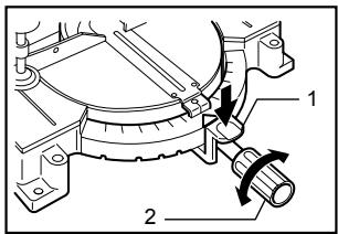
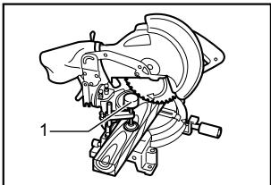
Adjusting the miter angle
007768
- Lock lever
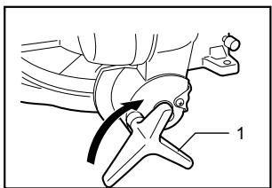
- Grip
Loosen the grip by turning counterclockwise. Turn the turn base while pressing down the lock lever. When you have moved the grip to the position where the pointer points to the desired angle on the miter scale, securely tighten the grip clockwise.
CAUTION:
- When turning the turn base, be sure to raise the handle fully.
After changing the miter angle, always secure the turn base by tightening the grip firmly.
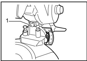
Adjusting the bevel angle
1. Knob
007763

1. Pointer
007757
To adjust the bevel angle, loosen the knob at the rear of the tool counterclockwise.
Push the handle to the left to tilt the saw blade until the pointer points to the desired angle on the bevel scale. Then tighten the knob clockwise firmly to secure the arm.
CAUTION:
- When tilting the saw blade, be sure to raise the handle fully.
After changing the bevel angle, always secure the arm by tightening the knob clockwise.
Switch action
CAUTION:
- Before plugging in the tool, always check to see that the switch trigger actuates properly and returns to the "OFF" position when released.
1. Switch trigger
007761
To start the tool, simply pull the switch trigger. Release the switch trigger to stop.
No lock button or similar for locking the switch on is
provided on the tool, but a hole is provided for insertion of a padlock to lock the tool off.
WARNING:
- NEVER use tool without a fully operative switch trigger. Any tool with an inoperative switch is HIGHLY DANGEROUS and must be repaired before further usage.
ASSEMBLY
CAUTION:
Always be sure that the tool is switched off and unplugged before carrying out any work on the tool.
Installing or removing saw blade
CAUTION:
Always be sure that the tool is switched off and unplugged before installing or removing the blade.
Use only the Makita wrench provided to install or remove the blade. Failure to do so may result in overtightening or insufficient tightening of the hex bolt. This could cause an injury.
When removing or installing the blade, keep the handle in the raised position.
- Wrench
- Center cover
00771
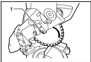
To remove the blade, use the wrench to loosen the hex bolt holding the center cover by turning it counterclockwise. Raise the blade guard and center cover.
- Hex bolt
007774
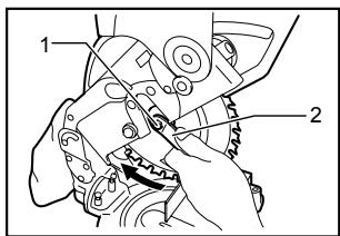
Press the shaft lock to lock the spindle and use the wrench to loosen the hex bolt clockwise. Then remove the hex bolt, outer flange and blade.
007770
- Hex bolt
- Wrench
To install the blade, mount it carefully onto the spindle, making sure that the direction of the arrow on the surface of the blade matches the direction of the arrow on the blade case. Install the outer flange and hex bolt, and then use the wrench to tighten the hex bolt (left-handed) securely counterclockwise while pressing the shaft lock.
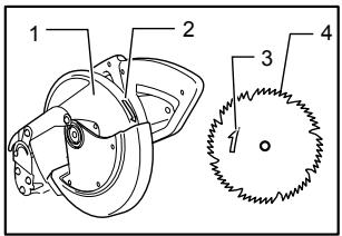
007808
- Blade case
- Arrow
- Arrow
- Saw blade
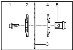
001786
- Hex bolt
- Outer flange
- Saw blade
- Inner flange
- Spindle
Install the outer flange and hex bolt, and then use the wrench to tighten the hex bolt (left-handed) securely counterclockwise while pressing the shaft lock.
Return the blade guard and center cover to its original position. Then tighten the hex bolt clockwise to secure the center cover. Lower the handle to make sure that the blade guard moves properly. Make sure shaft lock has released spindle before making cut.
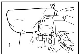
Dust bag
007775
1. Dust bag
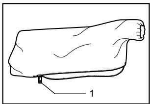
007776
1. Fastener
The use of the dust bag makes cutting operations clean and dust collection easy. To attach the dust bag, fit it onto the dust nozzle.
When the dust bag is about half full, remove the dust bag from the tool and pull the fastener out. Empty the dust bag of its contents, tapping it lightly so as to remove particles adhering to the insides which might hamper further collection.
NOTE:
If you connect a Makita vacuum cleaner to your saw, more efficient and cleaner operations can be performed.
Securing workpiece
WARNING:
It is extremely important to always secure the workpiece properly and tightly with the vise. Failure to do so can cause the tool to be damaged and/or the workpiece to be destroyed. PERSONAL INJURY MAY ALSO RESULT. Also, after a cutting operation, DO NOT raise the blade until the blade has come to a complete stop.
CAUTION:
- When cutting long workpieces, use supports that are as high as the top surface level of the turn base. Do not rely solely on the vertical vise and/or horizontal vise to secure the workpiece.
Thin material tends to sag. Support workpiece over its entire length to avoid blade pinch and possible KICKBACK.
001549
- Support
- Turn base
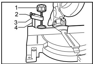
Vertical vise
007762
- Vise knob
- Screw
- Vise arm
- Vise rod
The vertical vise can be installed in two positions on either the left or right side of the guide fence. Insert the vise rod into the hole in the guide fence and tighten the screw to secure the vise rod.
Position the vise arm according to the thickness and shape of the workpiece and secure the vise arm by tightening the screw. Make sure that no part of the tool contacts the vise when lowering the handle all the way. If some part contacts the vise, re-position the vise.
Press the workpiece flat against the guide fence and the turn base. Position the workpiece at the desired cutting position and secure it firmly by tightening the vise knob.
CAUTION:
The workpiece must be secured firmly against the turn base and guide fence with the vise during all operations.
OPERATION
CAUTION:
Before use, be sure to release the handle from the lowered position by pulling the stopper pin.
Make sure the blade is not contacting the workpiece, etc. before the switch is turned on.
- Do not apply excessive pressure on the handle when cutting. Too much force may result in overload of the motor and/or decreased cutting efficiency. Push down handle with only as much force as is necessary for smooth cutting and without significant decrease in blade speed.
Gently press down the handle to perform the cut. If
the handle is pressed down with force or if lateral force is applied, the blade will vibrate and leave a mark (saw mark) in the workpiece and the precision of the cut will be impaired.
1. Press cutting
1. Vertical vise
007765
Secure the workpiece with the vise. Switch on the tool without the blade making any contact and wait until the blade attains full speed before lowering. Then gently lower the handle to the fully lowered position to cut the workpiece. When the cut is completed, switch off the tool and WAIT UNTIL THE BLADE HAS COME TO A COMPLETE STOP before returning the blade to its fully elevated position.
2. Miter cutting
Refer to the previously covered "Adjusting the miter angle".
3. Bevel cut
007764
Loosen the knob and tilt the saw blade to set the bevel angle (Refer to the previously covered "Adjusting the bevel angle"). Be sure to retighten the knob firmly to secure the selected bevel angle safely. Secure the workpiece with a visse. Switch on the tool without the blade making any contact and wait until the blade attains full speed. Then gently lower the handle to the fully lowered position while applying pressure in parallel with the blade. When the cut is completed, switch off the tool and WAIT UNTIL THE BLADE HAS COME TO A COMPLETE STOP before returning the blade to its fully elevated position.
CAUTION:
Always be sure that the blade will move down to bevel direction during a bevel cut. Keep hands out of path of saw blade.
During a bevel cut, it may create a condition whereby the piece cut off will come to rest against the side of the blade. If the blade is raised while the blade is still rotating, this piece may be caught by the blade, causing fragments to be scattered which is dangerous. The blade should be raised ONLY after the blade has come to a complete stop.
- When pressing the handle down, apply pressure parallel to the blade. If the pressure is not parallel to the blade during a cut, the angle of the blade might be shifted and the precision of the cut will be impaired.
4. Compound cutting
Compound cutting is the process in which a bevel angle is made at the same time in which a miter angle is being cut on a workpiece. Compound cutting can be performed at angle shown in the table.
| Bevel angle | Miter angle |
| 45° | Left and Right 0° - 45° |
006366
When performing compound cutting, refer to "Press cutting", "Miter cutting" and "Bevel cut" explanations.
5. Cutting aluminum extrusion
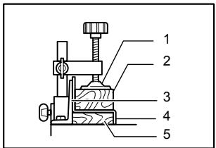
001844
When securing aluminum extrusions, use spacer blocks or pieces of scrap as shown in the figure to prevent deformation of the aluminum. Use a cutting lubricant when cutting the aluminum extrusion to prevent build-up of the aluminum material on the blade.
CAUTION:
- Never attempt to cut thick or round aluminum extrusions. Thick aluminum extrusions may come loose during operation and round aluminum extrusions cannot be secured firmly with this tool.
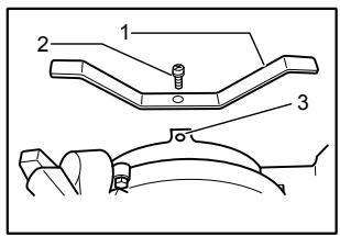
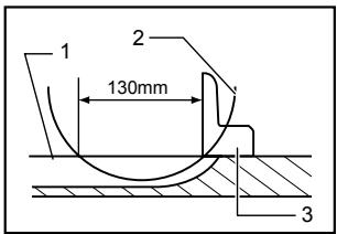
6. Wood facing
Use of wood facing helps to assure splinter-free cuts in workpieces. Attach a wood facing to the guide fence using the holes in the guide fence.
See the figure concerning the dimensions for a suggested wood facing.
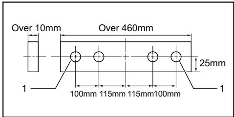
- Hole
007833
CAUTION:
Use straight wood of even thickness as the wood facing.
Use screws to attach the wood facing to the guide fence. The screws should be installed so that the screw heads are below the surface of the wood facing.
- When the wood facing is attached, do not turn the turn base with the handle lowered. The blade and/or the wood facing will be damaged.
The maximum cutting width will be smaller by the width of wood facing.
7. Cutting repetitive lengths
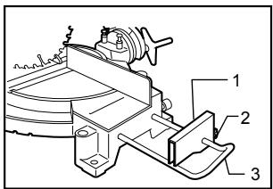
- Set plate
- Screw
- Holder
007760
When cutting several pieces of stock to the same length, ranging from 240mm to 380mm , use of the set plate (optional accessory) will facilitate more efficient operation. Install the set plate on the holder (optional accessory) as shown in the figure. Align the cutting line on your workpiece with either the left or right side of the groove in the kerf board, and while holding the workpiece from moving, move the set plate flush against the end of the workpiece. Then secure the set plate with the screw. When the set plate is not used, loosen the screw and turn the set plate out of the way.
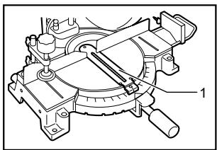
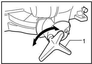
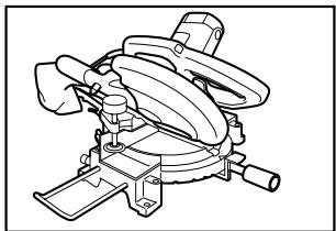
Carrying tool
1. Stopper pin
1. Miter angle
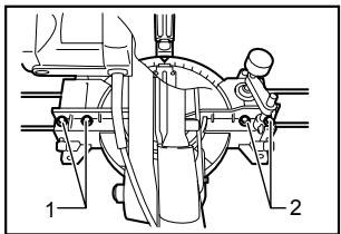
1. Hex bolts
2. Hex bolts
007754
Make sure that the tool is unplugged. Secure the blade at 0^ bevel angle and the turn base at left miter angle fully. Lower the handle fully and lock it in the lowered position by pushing in the stopper pin.
Carry the tool by carrying grip as shown in the figure. If you remove the holders, dust bag, etc., you can carry the tool more easily.
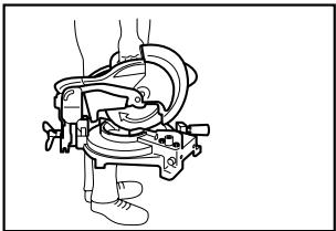
007759
CAUTION:
Always secure all moving portions before carrying the tool.
- Stopper pin is for carrying and storage purposes only and not for any cutting operations.
MAINTENANCE
CAUTION:
Always be sure that the tool is switched off and unplugged before attempting to perform inspection or maintenance.
WARNING:
Always be sure that the blade is sharp and clean for the best and safest performance.
Adjusting the cutting angle
This tool is carefully adjusted and aligned at the factory, but rough handling may have affected the alignment. If your tool is not aligned properly, perform the following:
Loosen the grip which secures the turn base. Turn the turn base so that the pointer points to 0^ on the miter scale. Tighten the grip and loosen the hex bolts securing the guide fence using the wrench. If the pointer does not point to 0^ on the miter scale, loosen the screw which secures the pointer and move and secure the pointer plate so that the pointer points to 0^ on the miter scale.
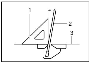
Lower the handle fully and lock it in the lowered position by pushing in the stopper pin. Square the side of the blade with the face of the guide fence using a triangular rule, try-square, etc. Then securely tighten the hex bolts on the guide fence in the order from the right side.
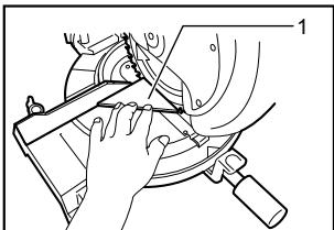
1. Triangular rule
007758
2. Bevel angle
(1) 0^ bevel angle
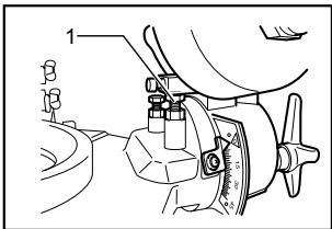
1.0° adjusting bolt
007752
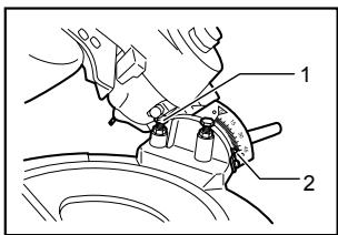
Lower the handle fully and lock it in the lowered position by pushing in the stopper pin. Loosen the knob at the rear of the tool. Loosen the hex nut and turn the 0^ bevel angle adjusting bolt on the right side of the turn base two or three revolutions clockwise
to tilt the blade to the right.
Carefully square the side of the blade with the top surface of the turn base using the triangular rule, try-square, etc. by turning the 0^ bevel angle adjusting bolt counterclockwise. Then tighten the hex nut to secure the 0^ bevel angle adjusting bolt and tighten the knob securely.
Make sure that the pointer on the arm points to 0^ on the bevel scale. If it does not point to 0^ on the bevel scale, loosen the screw which secures the pointer and move and secure the pointer plate so that the pointer points to 0^ on the bevel scale.
001819
- Triangular rule
- Saw blade
- Top surface of turn base
007757
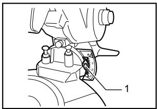
1. Pointer
(2) 45^ bevel angle
1.45° bevel angle adjusting bolt
2. Pointer
007751
Adjust the 45^ bevel angle only after performing 0^ bevel angle adjustment. To adjust left 45^ bevel angle, loosen the knob and tilt the blade to the left fully. Make sure that the pointer on the arm points to 45^ on the bevel scale on the arm. If the pointer does not point to 45^ , turn the 45^ bevel angle adjusting bolt on the left side of the arm until
the pointer points to 45^ .
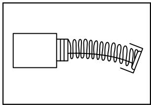
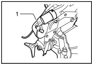
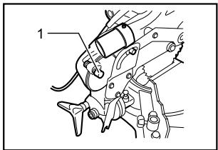
Replacing carbon brushes
007834
Remove and check the carbon brushes regularly. Replace when they wear down to 3mm in length. Keep the carbon brushes clean and free to slip in the holders. Both carbon brushes should be replaced at the same time. Use only identical carbon brushes.
Use a screwdriver to remove the brush holder caps. Take out the worn carbon brushes, insert the new ones and secure the brush holder caps.
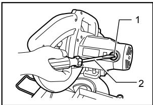
007756
- Brush holder cap
- Screwdriver
After use
After use, wipe off chips and dust adhering to the tool with a cloth or the like. Keep the blade guard clean according to the directions in the previously covered section titled "Blade guard". Lubricate the sliding portions with machine oil to prevent rust.
To maintain product SAFETY and RELIABILITY, repairs, any other maintenance or adjustment should be performed by Makita Authorized Service Centers, always using Makita replacement parts.
FRANÇAIS SPÉCIFICATIONS
Modèle
MLS100
Diametre de la lame
255 mm (10")
Diametre de l'orifice
15.88 mm(5/8")
Angle d'onglet max.
Gauge 45^ , Droite 45^
Angle de biseau max.
Gauge 45^
- Plaque fixation
- Vis
- Support
007760
Some dust created by power sanding, sawing, grinding, drilling, and other construction activities contains chemicals known to the State of California to cause cancer, birth defects or other reproductive harm. Some examples of these chemicals are:
- lead from lead-based paints,
crystalline silica from bricks and cement and other masonry products, and - arsenic and chromium from chemically-treated lumber.
Your risk from these exposures varies, depending on how often you do this type of work. To reduce your exposure to these chemicals: work in a well ventilated area, and work with approved safety equipment, such as those dust masks that are specially designed to filter out microscopic particles.
< USA solamente >
ADVERTENCIA
3-11-8, Sumiyoshi-cho,
Anjo, Aichi 446-8502 Japan