MUL-605 - Multimeter Steren - Free user manual and instructions
Find the device manual for free MUL-605 Steren in PDF.


| Product Type | Digital Multimeter |
| Brand | Steren |
| Model | MUL-605 |
| Dimensions | Approx. 150 x 70 x 30 mm |
| Weight | Approx. 200 g (with battery) |
| Power Supply | 9V battery (6F22 or equivalent) |
| Display | LCD, 2000 counts |
| DC Voltage Range | 200 mV, 2 V, 20 V, 200 V, 600 V |
| AC Voltage Range | 200 V, 600 V |
| DC Current Range | 200 µA, 2 mA, 20 mA, 200 mA, 10 A |
| AC Current Range | 200 µA, 2 mA, 20 mA, 200 mA, 10 A |
| Resistance Range | 200 Ω, 2 kΩ, 20 kΩ, 200 kΩ, 2 MΩ |
| Additional Functions | Continuity test, diode test, battery test, transistor hFE test |
| Basic Accuracy (DCV) | ±0.5% |
| Safety Rating | CAT II 600 V |
| Fuse Protection | F 250 mA / 250 V (for mA range), F 10 A / 250 V (for 10A range) |
| Maintenance | Clean with dry cloth; avoid moisture and extreme temperatures |
| Included Accessories | Test leads, 9V battery, user manual |
| Warranty | 1 year |
| Repairability | Replaceable battery and fuse; test leads sold separately |
Frequently Asked Questions - MUL-605 Steren
User questions about MUL-605 Steren
0 question about this device. Answer the ones you know or ask your own.
Ask a new question about this device
Download the instructions for your Multimeter in PDF format for free! Find your manual MUL-605 - Steren and take your electronic device back in hand. On this page are published all the documents necessary for the use of your device. MUL-605 by Steren.
USER MANUAL MUL-605 Steren
natural_image
Technical line drawing of a mechanical device with a red curved arrow indicating rotation or motion (no text or symbols present)natural_image
Line drawing of a device with a wall socket and a separate electrical outlet (no text or symbols)CONEXIÓN A PC
STEREN PRODUCTO EMPACADO S.A. DE C.V.
Before to use the product, please read carefully this manual to avoid any malfunction. The info in this manual is shown as reference. Due to updates can exist differences. Consult our website www.steren.com to obtain the current version of this manual.

CAUTIONS
- The inappropriate use of this multimeter may cause damages, shock hazard or severe injuries.
• Always remove the test cables before to replace the batteries or fuse.
- Check the status of the test cables or the meter before to use it.
- Don't measure voltage that exceed 1000V over fisic ground; may be dangerous.
- Be careful when you take measures over 30 VCA RMS o 60V DC; this voltages may cause shock hazard.
• Always discharge the capacitors and cut the power of the device before to make diode test, resistance or continuity.
- To avoid damages in the meter, do not exceed the maximum limits of the input values that is shown in the specifications.
- Remove the batteries, in case the device won't be used for long periods of time
• This product is NOT a toy: keep it away from children.
- This device cannot be used by people with different abilities, unless they have preparation and supervision.
INDEX
DESCRIPTION 30
Parts 30
Selector knob 32
Symbols in the screen 33
BATTERY PLACEMENT 34
HOW TO USE 35
Voltage measuring 35
Current measuring 36
Resistance measuring 37
Diode test 37
Continuity testing 38
Capacitance measuring 38
Frequency measuring 39
Temperature measuring 39
Non-contact voltage detection (NCV) 40
PC CONNECTION 41
Software installation 41
Driver installation 42
Software use 42
ANOTHER FUNCTIONS 44
MEASURING SPECIFICATIONS 45
Direct current voltage 45
Alternating current voltage 45
DC current 46
AC current 46
Resistance 47
Diode and Continuity 47
Temperature 47
Frequency 48
Capacitance 48
DESCRIPTION
Parts
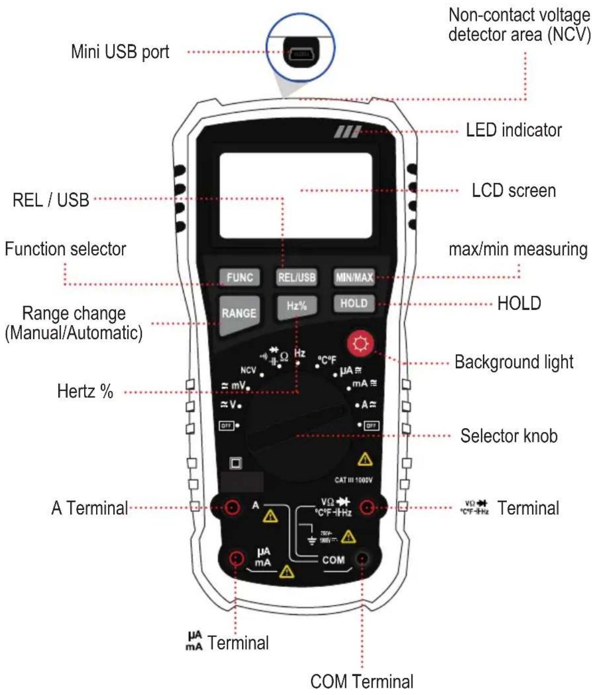
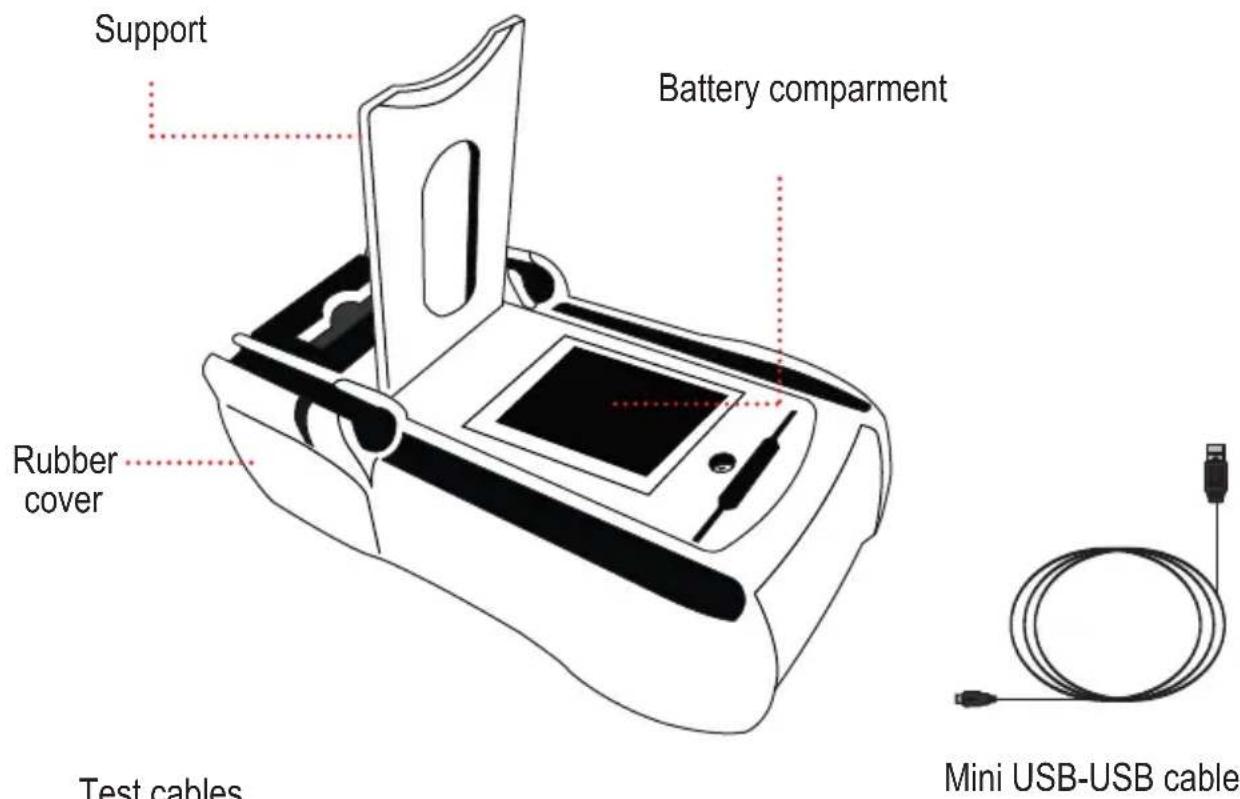
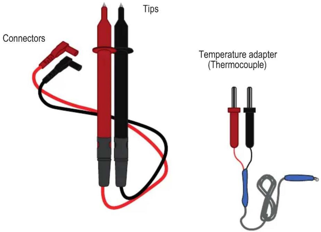
Test cables (red and black)
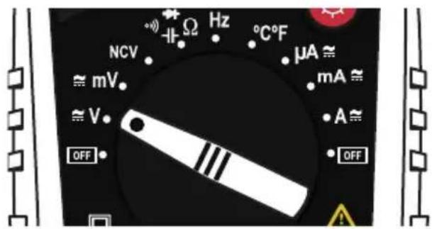
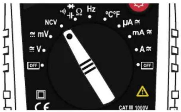
Selector knob
| Symbol Function | |
| OFF Off | |
| ≈ V | Direct current and Alternating current voltage in volts |
| ≈ mV | Direct current and Alternating current voltage in mili volts |
| NCV Non-contact voltage detection | |
| ○) | Continuity |
| + | Capacitance |
| + | Diodes |
| Ω | Resistance |
| Hz Frequency | |
| °C Temperature in cent | grades |
| °F Temperature in Fahrenheit | |
| μA ≈ | Direct current and Alternating current in micro ampers |
| mA ≈ | Direct current and Alternating current in mli ampers |
| A ≈ | Direct current and Alternating current in ampers |
Symbols in the screen
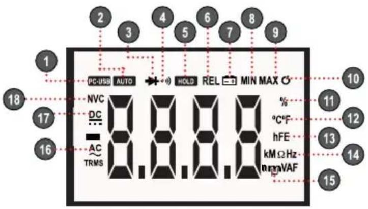
| 1 PC connection | |
| 2 Auto-range active | |
| 3 Diodes test | |
| 4 Continuity | |
| 5 Data hold | |
| 6 Relative mode | |
| 7 Battery status | |
| 8 Retention of minimum value | |
| 9 Retention of maximum value | |
| 10 Auto-off | |
| 11 Duty cycle measuring | |
| 12 Degrees: Celsius / Fahrenheit | |
| 13 Transistors measuring | |
| 14 Resistance unity: Kilo ohms / mega ohms / ohmsFrequency unity: Kilo hertz / mega hertz / hertz | |
| 15 Voltage unity: Volts / mili voltsCurrent unity: Micro amper / mili amper / amperCapacitance unity: micro faradio / mili faradio / faradio | |
| 16 Alternating current | |
| 17 Direct current | |
| 18 Non-contact voltage detection |
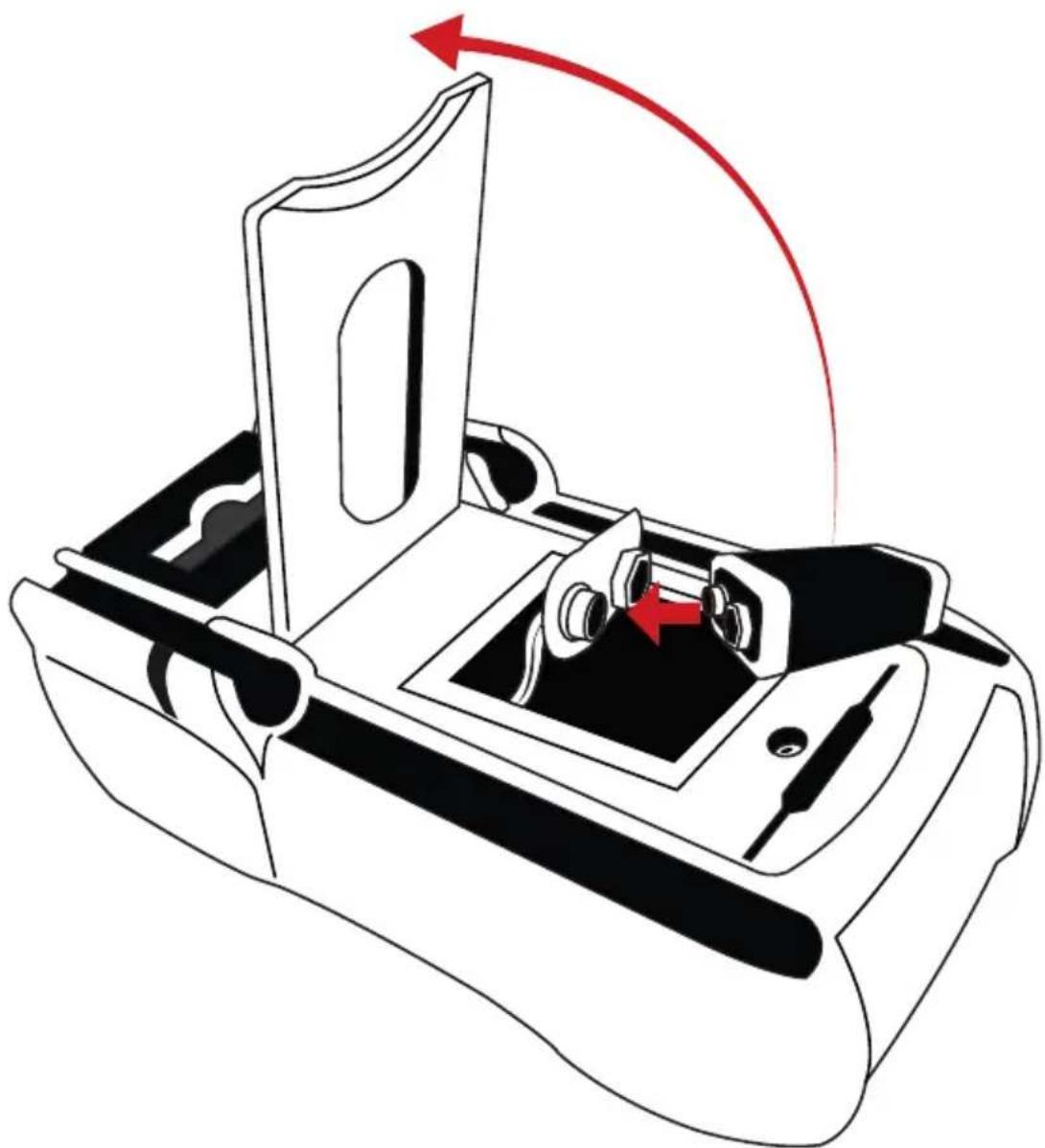
BATTERY PLACEMENT
Ensure that the polarity is right.
natural_image
Diagram of a device interior with a red curved arrow indicating rotation or movement, showing no text or symbols.If the - + symbol appears in the screen, means that the battery should be replaced.
HOW TO USE
The high voltage circuits, such as AC and DC, are very dangerous; they must be measured with cautions.
To avoid shock hazard or damage in the meter, performs measures higher than 1 000 VDC or 750VAC RMS.
Voltage measuring
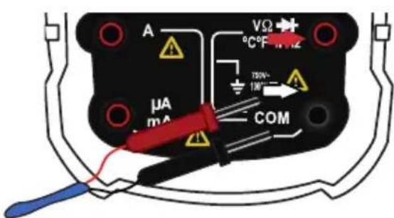
- Turn the knob to select the voltage type that you want to measure: ≈ V ≈ mV
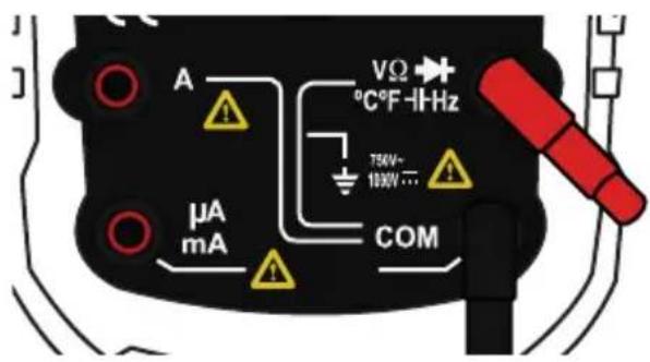
- Insert the black connector into the COM terminal; insert the red connector into terminal.
- Touch with the black tip in the negative side of the circuit; touch with the red tip in the positive side of the circuit.
Press FUNC to change to AC.
Current measuring
Never try to measure current when the voltage between the open circuit and the ground is higher than 250V.
Never place the test cables in parallel with a circuit or component when they are connected to the terminals.
- Remove the power supply and discharge the capacitors of the circuit.
- Adjust the knob to current measuring range A / mA / A .
- Insert the black connector into the COM terminal.
To make a measuring under than 400 mA insert the red connector into A_mA terminal; to measure between 400 mA and 10 A insert it in A terminal.
- Open the circuit. Connect the tips in the circuit in a way the current to flow through of multimeter (serial connection).
- Activate the energy in the circuit again.
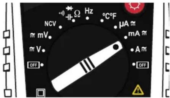
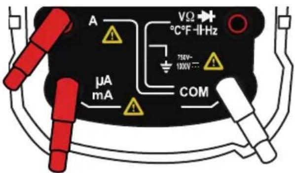
Press FUNC to change to AC.
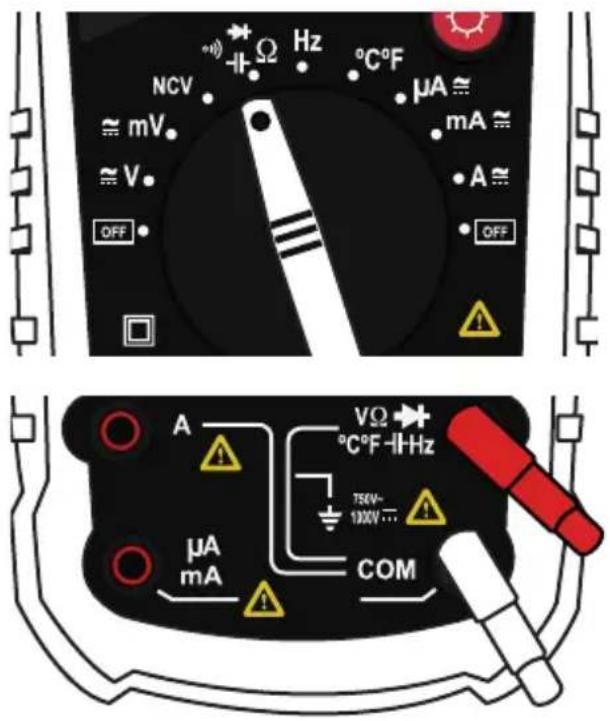
Resistance measuring

Ensure that the circuits haven't energy and the capacitors is discharged to avoid electrical hazard or damages in the equipment.
- Set the knob in position.
- Press the FUNC button until the symbol (Ω / kΩ / MΩ) appears in the screen.
- Insert the black connector into the COM terminal; insert the red connector into terminal.
- Touch the circuit with the tips.
Diode test

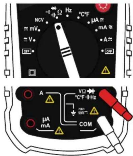
Be sure that the circuits have not energy and the capacitors are completely discharged to avoid hazard shock or damages in the equipment.
- Set the knob in position.
- Press the FUNC button until the symbol → appears in the screen.
- Insert the black connector into the COM terminal; insert the red connector into ^V ^+C^+F^- 1Hz terminal.
- Connect the tips to the semiconductor component: the red to anode and the black to cathode.
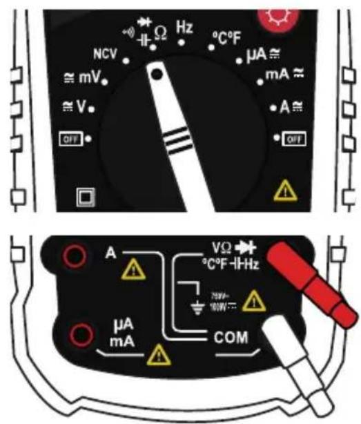
Continuity testing
- Set the knob in position.
- Press the FUNC button until the symbol 🔊 appears in the screen.
- Insert the black connector into the COM terminal; insert the red connector into VΩ → °C°F-1Hz terminal.
- Touch with the tips the circuit or wire that you want to check.
The resistance value will shown in the screen, if the resistance is lower than 30 , the signal will be audible.
Capacitance measuring
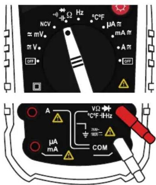
Before to make the measuring, ensure that the capacitor is disconnected from any circuit.
- Set the knob in _^* position.
- Press the FUNC button until the symbol (n F) appears in the screen.
- Insert the black connector into the COM terminal; insert the red connector into terminal.
- Touch the circuit with the tips.
Frequency measuring

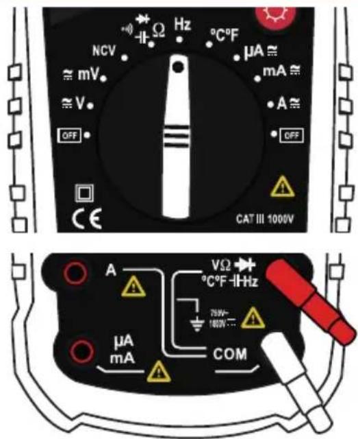
To avoid electrical hazard or damages in the multimeter, do not measure frequencies in high voltages (>250V)
- Set the knob in Hz position.
- Insert the black connector into the COM terminal; insert the red connector into terminal.
- Touch the circuit with the tips.
- Press to measuring the work duty.
Temperature measuring

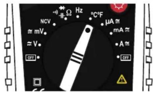
To avoid shock hazard, do not measure temperature if the input voltage exceed 36 V DC or 36 V AC RMS.
- Set the knob in °C / °F position.
- Press the FUNC button to choose the unity temperature
°C = Centigrades
°F = Fahrenheit - Insert the black connector into the COM terminal; insert the red connector into terminal.
- Touch with the adapter the piece where you want to measure the temperature; keep the contact until the measure is stabilized.
Non-contact voltage detection (NCV)
- Set the knob in NCV position.
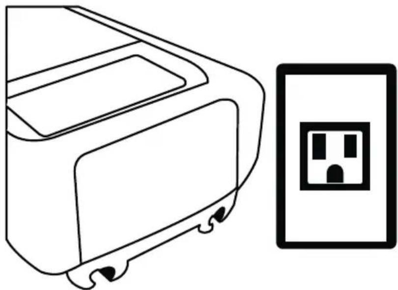
- Near the top of the multimeter to the equipment or component that you want to check (wire, contact, socket).
In case of voltage detection, the indicator LED will flash and the equipment will emit an audible signal
The circuit design, the insulation thickness and others variables may cause interference in the detection
The interference sources, as lanterns, engines may cause wrong detection
natural_image
Line drawing of a washing machine next to an electrical outlet (no text or symbols)PC CONNECTION
The showed software is not property of Steren; the company is not responsible by the working or updates.
The showed images correspond to a PC with Windows 10. The install process and the working may vary in accord with the OS version used.
Software installation
- Insert the CD of installation, search and execute the Setup file.
- If is necessary give installation permissions, click Next.
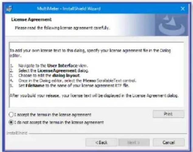
- You must accept the terms and conditions. Click Next.
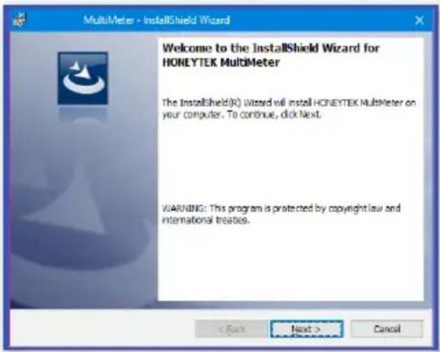
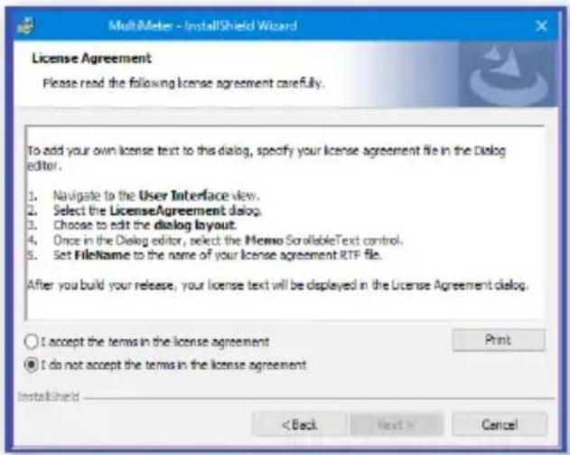
- Click Next in the followed windows until finish the installation process.
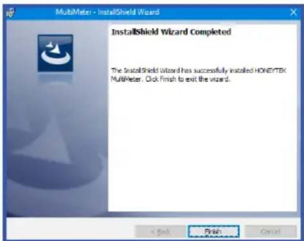
Driver installation
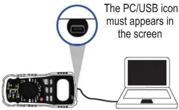
- Turn on the multimeter and connect it to a PC.
- Press RELEASE for a few seconds to establish the connection.
- In the folder CP210x_Windows_Drivers select the corresponding driver to the PC featurings. Twice click to install it.
| x64 | 04/05/2016 07:42 ... | Carpeta de arc |
| x86 | 04/05/2016 07:42 ... | Carpeta de arc |
| CP210xVCPinstaller_x64 | 28/03/2016 08:38 ... | Aplicación |
| CP210xVCPInstaller_x86 | 28/03/2016 08:38 ... | Aplicación |
| dpinst | 28/03/2016 08:32 ... | Documento XM |
| SLAB_License_Agreement_VCP_Windows | 28/03/2016 08:32 ... | Documento de |
Software use
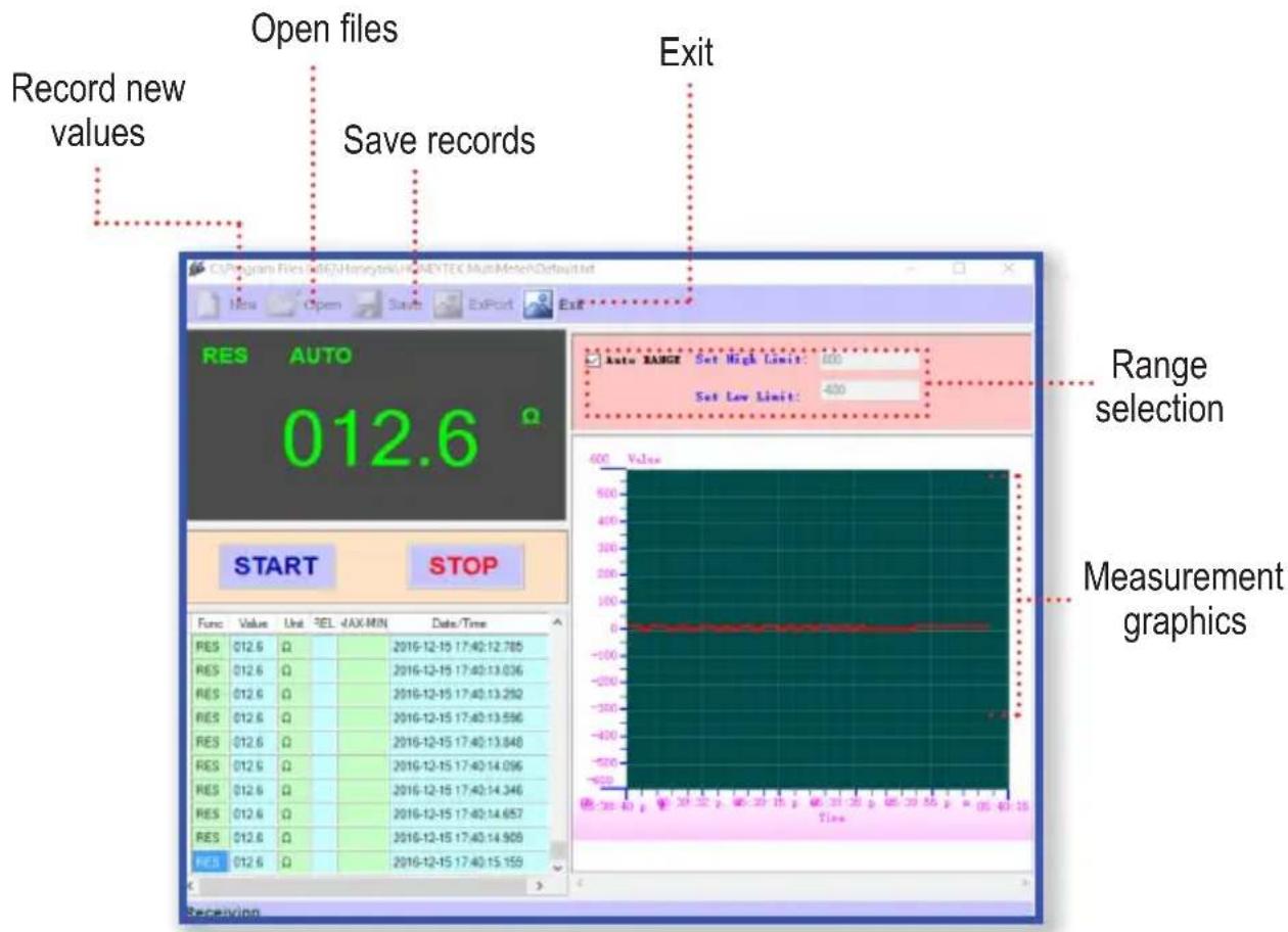
- With the multimeter on and connected, twice click in the direct access created in the desktop.
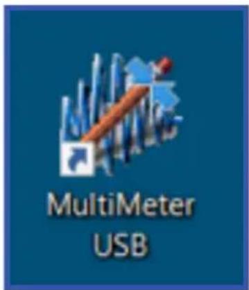
- Click START to check the connection and visualizing continuous measurements. Select STOP to finish the measurements.
ANOTHER FUNCTIONS
Relative mode
Allows to measure in relations with a value of stored reference. The visualized value is the difference between the value of reference and the measured value.
Auto-off

If the multimeter remains turn on for 15 minutes without working, it will enter in stand by status and will off to save energy
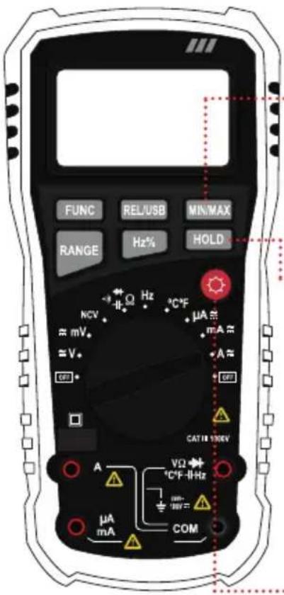
Max / min reading
Press once to hold in screen the maximum reading (MAX) or minimum (MIN). This reading will be updated when is recorded a new value max or min.
HOLD
After to a measure, press once to hold the reading in the screen.
Background light
Press to turn on the light of the screen.
MEASURING SPECIFICATIONS
Direct current voltage
| Range Resolution Accuracy | |
| 40mV/60mV 0.01mV | |
| 400mV/600mV 0.1mV | |
| 4V/6V 0.001V | |
| 40V/60V 0.01V | |
| 400V/600V 0.1V | |
| 1000V 1V ±(1.8% reading) |
Input impedance: 10MΩ; Maximum input voltage: 1000V DC
Alternating current voltage
| Range Resolution Accuracy | |
| 40mV/60mV 0.01mV ±(1.0% reading) | |
| 400mV/600mV 0.1mV ±(1.0% reading) | |
| 4V/6V 0.001V | |
| 40V/60V 0.01V | |
| 400V/600V 0.1V | |
| 750V 1V ±(1.0% reading) |
Input Impedance: 10MΩ / Maximum Input Voltage: 750VAC RMS / Frequency Range: 40-1000 Hz
DC Current
| Range Resolution Accuracy | |
| 400μA /600μA 0.1μA | |
| 4mA/6mA 0.001mA | |
| 40mA/60mA 0.01mA | |
| 400mA/600mA 0.01mA | |
| 4A/6A 0.001A | |
| 10A 001mA |
Input Impedance: 10MΩ / Maximum Input Voltage: 750V AC RMS
AC Current
| Range Resolution Accuracy | |
| 400μA /600μA 0.1μA | |
| 4mA/6mA 0.001mA | |
| 40mA/60mA 0.01mA | |
| 400mA/600mA 0.01mA | |
| 4A/6A 0.001A | |
| 10A 001mA |
Overload protection: FF500mA / 1000V fuse for mA range; Fuse FF10A / 500V to 10A Frequency range: 40 \~ 1000Hz
Resistance
| Range Resolution Accuracy | |
| 400kΩ/600kΩ 0.1 kΩ ±(1,0% lectura) | ±(0.8% reading) |
| 4kΩ/6kΩ 0.001 kΩ | |
| 40kΩ/60kΩ 0.01 kΩ | |
| 400MΩ/600kΩ 0.1 kΩ | |
| 4MΩ/6MΩ 0.001 MkΩ | |
| 40MΩ/60MΩ 0.01 MkΩ ±(1.2% reading) |
Overload protection: 250V DC or 250V AC RMS
Diode and continuity
| Range Function | |
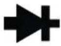 | Approx voltage of diode |
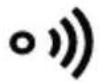 | The alarm will emit a sound if the resistance is lower than to 30Ω |
Temperature
| Range Resolution Accuracy | ||
| -20 °C ~ 400 °C | 1°C | ±(2.0% reading) |
| -400 °C ~ 1000 °C | ||
| 0 °F ~ 752 °F 0,01 kΩ | 1°F | ±(2.0% reading) |
| 752 °F ~ 1832 °F | ||
Overload protection: 250V DC or 250V AC RMS
Frequency
| Range Resolution Accuracy | |
| 10Hz 0.01Hz ±(1,0% lectura) | ±(0.5% reading) |
| 100Hz 0.1Hz | |
| 1kHz 0.001kHz | |
| 10 kHz 0.01kHz | |
| 100kHz 0.1 kHz | |
| 1MHz 0.001MHz | |
| 10MHz 0.01MHz |
Overload protection: 250V DC or 250V AC RMS
Capacitance
| Range Resolution Accuracy | |
| 10nF 0.01nF ±(1,0% lectura) | ±(4.0% reading) |
| 100nF 0.1nF | |
| 1μF 0.001μF | |
| 10μF 0.01μF | |
| 100μF 0.1μF | |
| 1mF 1μF | ±(5.0% reading) |
| 10mF 10μF | |
| 100mF 100μF |
Overload protection: 250V DC or 250V AC RMS
SPECIFICATIONS
Input: 9V --- (square battery)
DC voltage range: 60mV – 1 000V
AC voltage range: 60mV – 750V
Resistance: 600-60Mohms
AC current range: 600 uA – 10A
DC current range: 600 uA – 10A
Capacitance range: 10nF-100mF
Frequency range: 10Hz-10MHz
Temperature range: 0-1 000°C
Operating temperature: 0-40 °C
Storing temperature: -10 to 60°C
Consumption: 0.1mW/h
Stand-by power consumption: Not applicable
Specifications may change without notice

STEREN
Product: USB professional digital multitester
Number part: MUL-605
Brand: Steren
This Steren product is warranted under normal usage against defects in workmanship and materials to the original purchaser for one year from the date of purchase.
CONDITIONS
- This warranty card with all the required information, invoice or purchase ticket, product box or package, and product, must be presented when warranty service is required.
- If the product is in the warranty time, the company will repair it free of charge.
- The repairing time will not exceed 30 natural days, from the day the claim was received.
- Steren sell parts, components, consumables and accessories to customer, as well as warranty service, at any of the addresses mentioned later.
THIS WARRANTY IS VOID IN THE NEXT CASES:
If the product has been damaged by an accident, acts of God, mishandling, leaky batteries, failure to follow enclosed instructions, improper repair by unauthorized personnel, improper safe keeping, among others.
a) The consumer can also claim the warranty service in the purchase establishment.
b) If you lose the warranty card, we can reissue it, if you show the invoice or purchase ticket.
RETAILER INFORMATION
Name of the retailer
Address
Product
Brand
Serial number
Date of delivery
In case your product fails or have questions, please contact your nearest dealer. If you are in Mexico, please call to our Call Center.
01 800 500 9000

natural_image
Abstract blue circular logo with horizontal stripes (no text or symbols)STEREN
- CONEXIÓN A PC
- CAUTIONS
- INDEX
- DESCRIPTION 30
- BATTERY PLACEMENT 34
- HOW TO USE 35
- PC CONNECTION 41
- ANOTHER FUNCTIONS 44
- MEASURING SPECIFICATIONS 45
- DESCRIPTION
- Parts
- BATTERY PLACEMENT
- HOW TO USE
- Voltage measuring
- Current measuring
- Resistance measuring
- Diode test
- Continuity testing
- Capacitance measuring
- Frequency measuring
- Temperature measuring
- Non-contact voltage detection (NCV)
- PC CONNECTION
- Software installation
- Driver installation
- Software use
- ANOTHER FUNCTIONS
- Relative mode
- Auto-off
- Max / min reading
- HOLD
- Background light
- MEASURING SPECIFICATIONS
- Direct current voltage
- Alternating current voltage
- SPECIFICATIONS
- CONDITIONS
- THIS WARRANTY IS VOID IN THE NEXT CASES:
- RETAILER INFORMATION
- STEREN
Brand : Steren
Model : MUL-605
Category : Multimeter