MUL-282 - Multimeter Steren - Free user manual and instructions
Find the device manual for free MUL-282 Steren in PDF.


| Product Type | Digital Multimeter with Auto Range Voltage Detector |
| Brand | Steren |
| Model | MUL-282 |
| Power Supply | 3V (2 x AAA batteries) |
| DC Voltage Range | 200 mV - 500 V |
| AC Voltage Range | 200 mV - 500 V |
| DC Current Range | 200 μA - 10 A |
| AC Current Range | 200 μA - 10 A |
| Resistance Range | 200 Ω - 20 MΩ |
| Temperature Range | -20°C to 750°C (-4°F to 1832°F) |
| Diode Test | Yes, approximate voltage drop |
| Continuity Test | Yes, audible alarm below ~70 Ω |
| Non-Contact Voltage Detector | Yes (NCV), visual and audible alarm |
| Data Hold | Yes |
| Auto Range | Yes |
| Overload Protection | Fuse: F200mA/250V (μA/mA) and 10A unfused range |
| Fuse Specifications | Fuse 1: 10ABS1362, Fuse 2: 200mABS1362 |
| Operating Temperature | 0°C to 40°C |
| Storage Temperature | -10°C to 60°C |
| Warranty | 1 year |
Frequently Asked Questions - MUL-282 Steren
User questions about MUL-282 Steren
0 question about this device. Answer the ones you know or ask your own.
Ask a new question about this device
Download the instructions for your Multimeter in PDF format for free! Find your manual MUL-282 - Steren and take your electronic device back in hand. On this page are published all the documents necessary for the use of your device. MUL-282 by Steren.
USER MANUAL MUL-282 Steren
natural_image
Diagram of a mechanical component with a red curved arrow indicating motion or force, no text or symbols presentnatural_image
Two batteries with green and gray casing, one white and one gray, shown in open position (no text or symbols)natural_image
Line drawing of a mechanical device with no visible text or symbolsDC = Corriente Directa
AC = Corriente Alterna
Prueba de diodos

natural_image
Simple electrical circuit diagram with battery, two black and red probes, and a plus sign (no text or symbols)natural_image
Pure electrical circuit lines without any symbolsnatural_image
Illustration of a multimeter with black, red, and blue probes connected by a coiled cable (no text or symbols)natural_image
Line drawing of a device with a separate electrical outlet symbol (no text or labels)MANTENIMIENTO
natural_image
Technical line drawing of a rectangular device with mounting points and internal components (no text or symbols)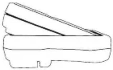
natural_image
Line drawing of a mechanical component with diagonal lines and base (no text or symbols)STEREN PRODUCTO EMPACADO S.A. DE C.V.
CENTRO DE ATENCIÓN
A CLIENTES
01 800 500 9000
MUL-282
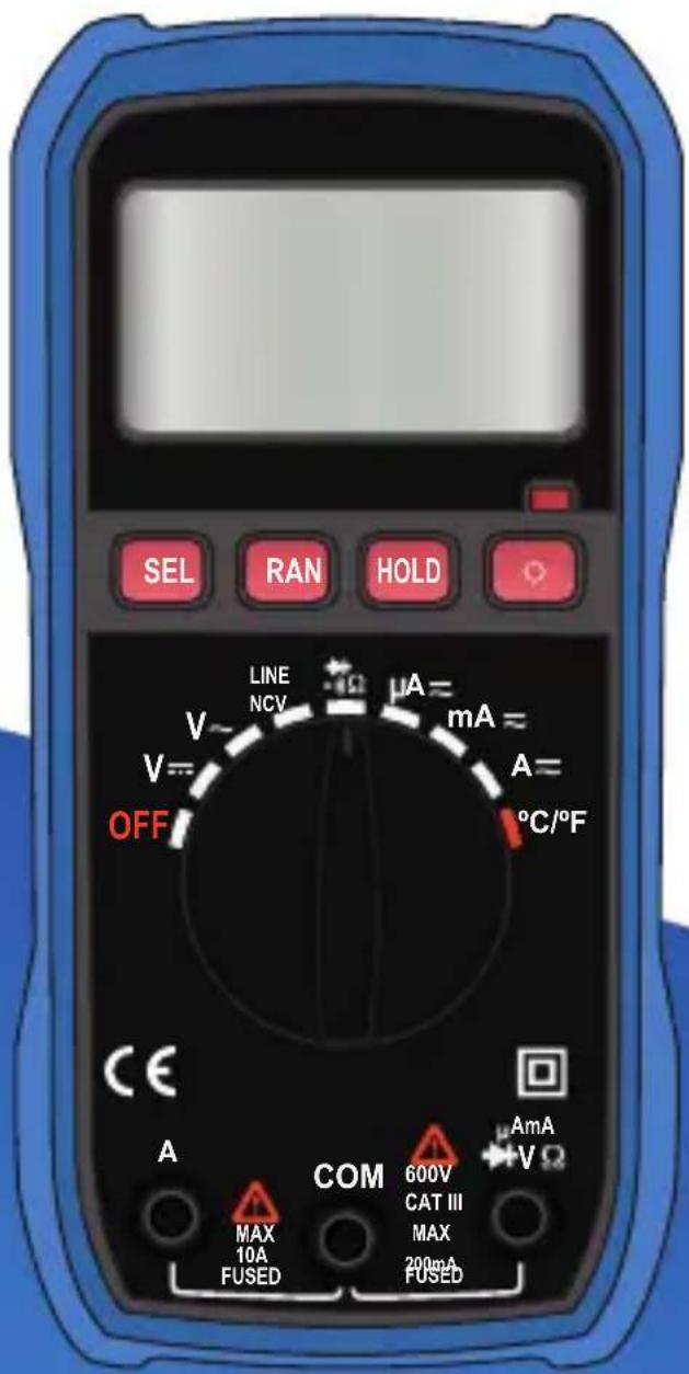
Digital Multimeter With Auto Range Voltage Detector
MUL-282
Before to use the product, please read carefully this manual to avoid any malfunction. The info in this manual is shown as reference. Due to updates can exist differences. Consult our website www.steren.com to obtain the most actual version of this manual.

CAUTIONS
- The inappropriate use of this multimeter may cause damages, shock hazard or severe injuries.
• Always remove the test cables before to replace the batteries or fuse. - Check the status of the test cables or the meter before to use it.
- Don’t measure voltage that exceed 1000V over fisic ground; may be dangerous.
- Be careful when you take measures over 30 VCA RMS o 60V DC; this voltages may cause shock hazard.
-
Always discharge the capacitors and cut the power of the device before to make diode test, resistance or continuity.
-
To avoid damages in the meter, do not exceed the maximum limits of the input values that is shown in the specifications.
- Remove the batteries, in case the device won’t be used for long periods of time
- This product is NOT a toy; keep it away from children.
- This device cannot be used by people with different abilities, unless they have preparation and supervision.
INDEX
DESCRIPTION 29
Parts 29
Selector knob 31
Symbols in the screen 32
BATTERIES REPLACEMENT 33
HOW TO USE 34
Voltage measuring 34
Current measurement 35
Diode test 37
Continuity testing 38
Temperature measuring 39
No-contact voltage detector (NVC) 40
MAINTENANCE 41
Fuse replacement 41
MEASURING SPECIFICATIONS 42
Direct current voltage 42
Alternating current voltage 43
DC Current 43
AC Current 44
Resistance 44
Diode and continuity 45
Temperature 45
DESCRIPTION
Parts
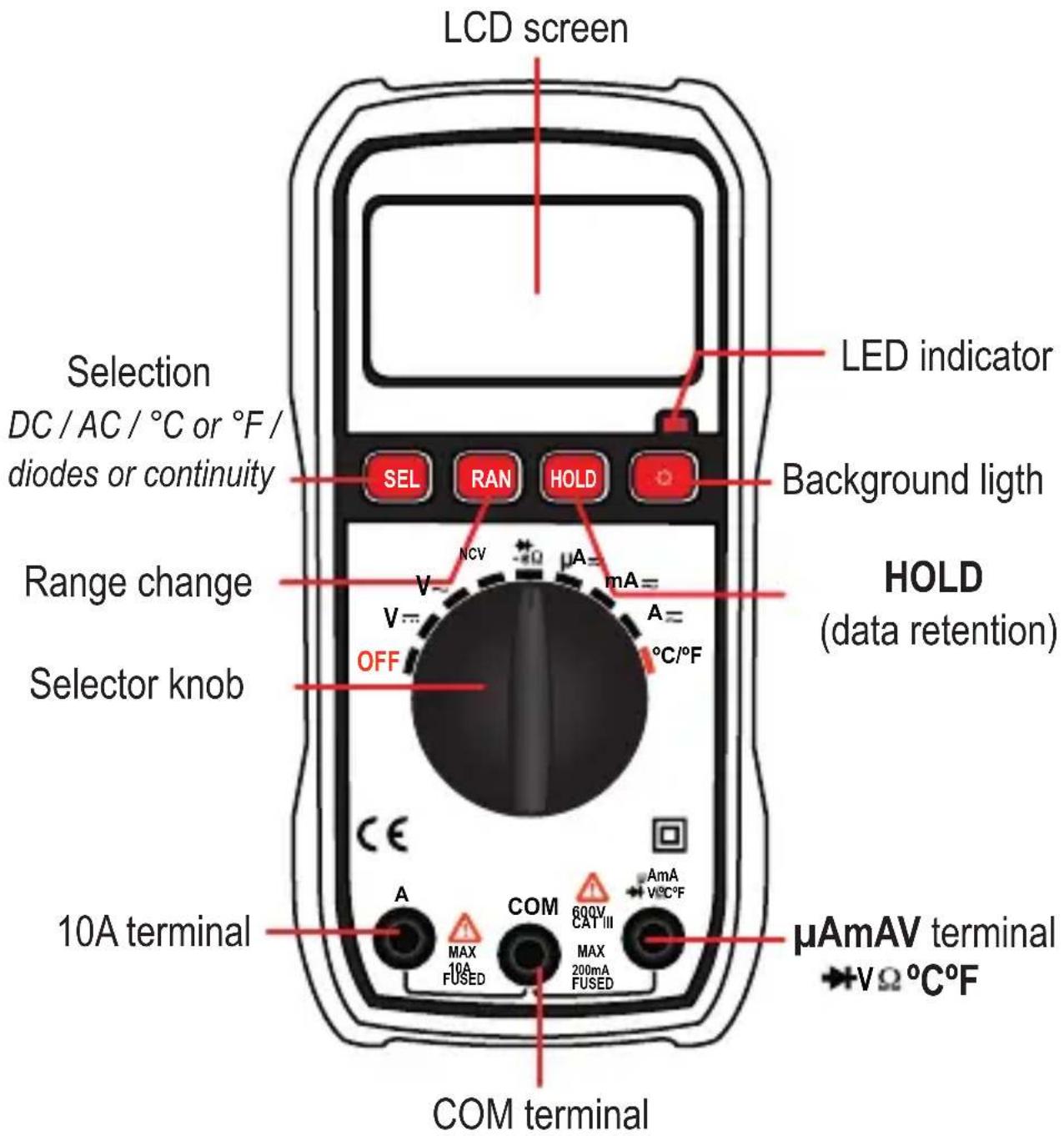
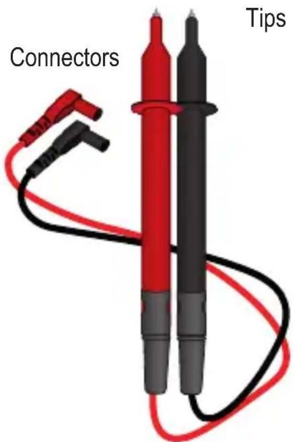
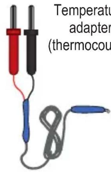
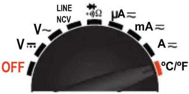
Selector knob
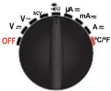
| OFF | Off |
| V= | Direct current voltage (DC) |
| V~ | Alternating current voltage (AC) |
| NCV | Non-contact voltage detector |
| Diode testContinuity testResistance measuring | |
| μA≈ | Direct current (DC) and Alternating Current (AC) in micro amperes |
| mA≈ | Direct current (DC) y Alternating Current (AC) in mili amperes |
| A≈ | DC and AC in amperes |
| °C/°F | Temperature in Centigrade gradesTemperature in Fahrenheit grades |
Symbols in the screen
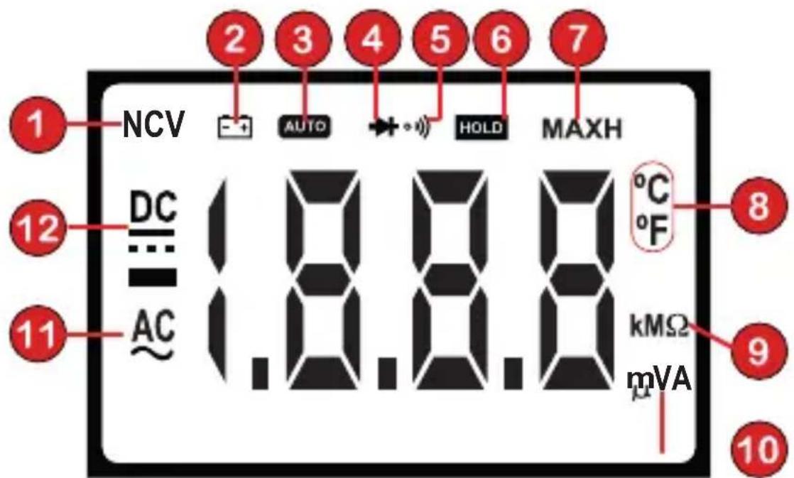
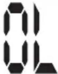
This indicate overload
- Non-contact voltage detector
- Low battery
- Auto-range activated
- Diode
- Continuity
- Data hold activated
-
Maximum measuring
-
Centigrades/Fahrenheit grades
- kilo ohm / mega ohm / ohm
- micro ampere / mili ampere / ampere /volt /mili volt/ ampere
- Alternating current
- Direct current
BATTERIES REMPLACEMENT
natural_image
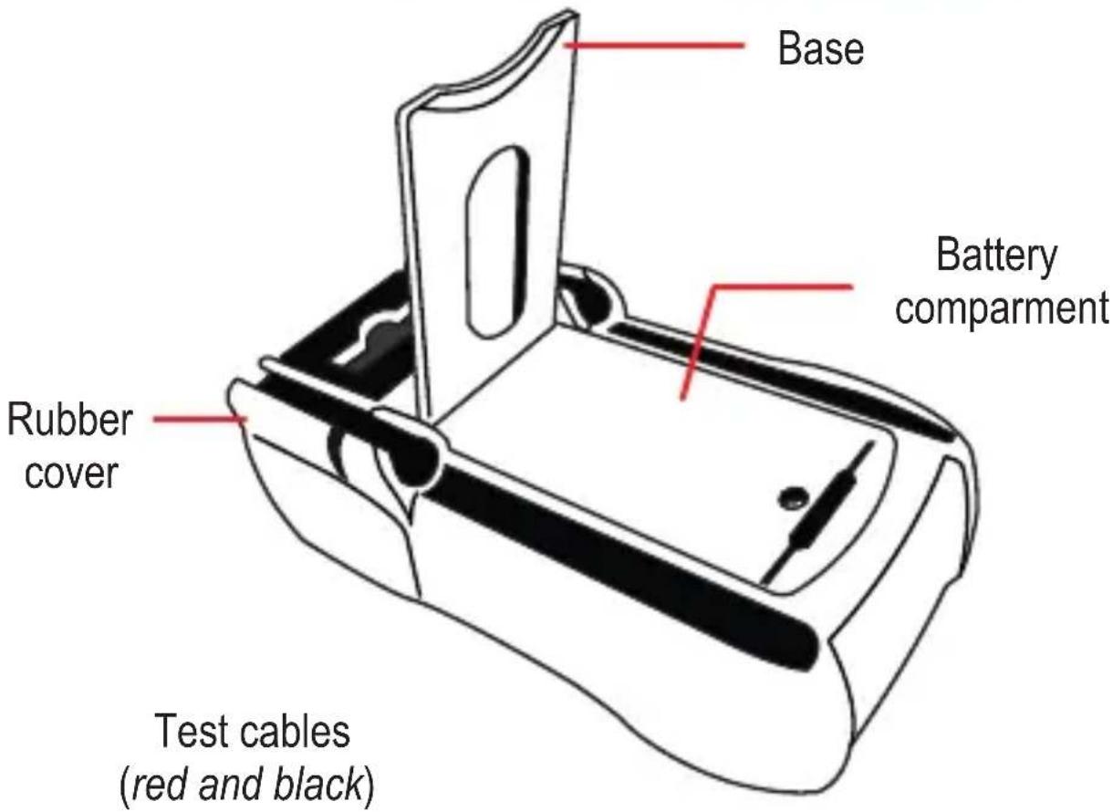
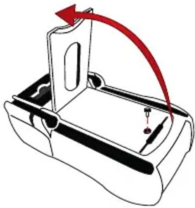
Diagram of a mechanical component with a red curved arrow indicating motion or force, no text or symbols presentPull up the support. Remove the screw and the cover
Remove the compartment. Place the batteries.
natural_image
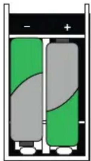
Two stacked batteries with green and gray casing, one white and one gray, shown in open position (no text or symbols)Ensure that the polarity is right
natural_image
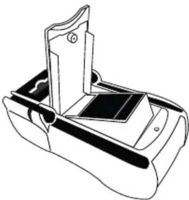
Line drawing of a mechanical device with a handle and internal components (no text or symbols)Set the compartment again. Down the cover and screw it again.
HOW TO USE
Voltage measuring

The high voltage circuits, such as AC and DC, are very dangerous; they must be measured with cautions.

To avoid shock hazard or damage in the meter, performs measures higher than 600 V DC.
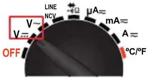
- Turn the knob to select the voltage type that you want to measure:
V --- DC
V \~ AC
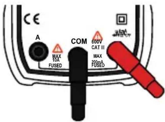
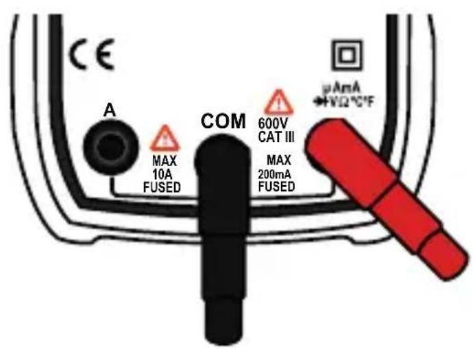
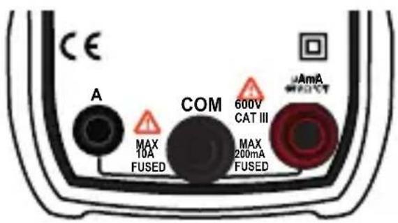
- Insert the black connector into the COM terminal; insert the red connector into AmA to terminal.
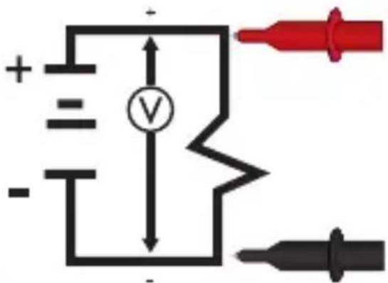
- Touch with the black tip in the negative side of the circuit; touch with the red tip in the positive side of the circuit.
Current measurement

Never try to measure current when the voltage between the open circuit and the ground is higher than 600V.

Never place the test cables in parallel with a circuit or component when they are connected to the terminals.
- Remove the power supply and discharge the capacitors of the circuit.
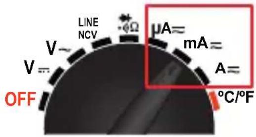
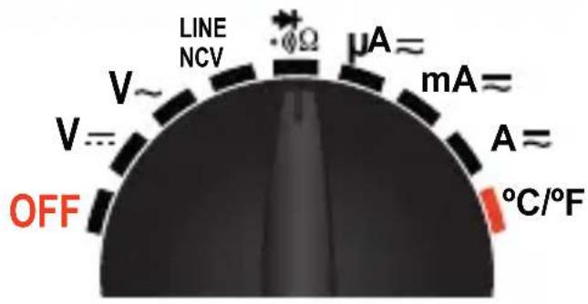
- Adjust the knob to current measuring range: A / mA / A .
- Press the SEL button to choose the current type:
DC
AC
- Insert the black connector into the COM terminal. To make a measuring less than 200 mA insert the red connector into A A terminal; to measure between 200 mA and 10 A insert the red connector into A terminal.
-
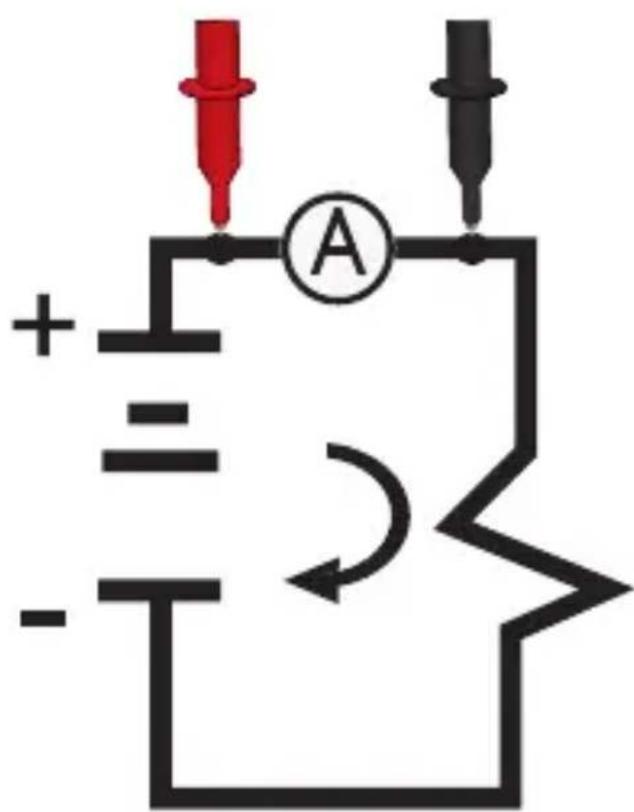
Open the circuit. Connect the tips into the circuit so that the current flows through the multimeter. (serial connection)
-
Activate the power in the circuit again.
Diode test

Be sure that the circuits have not energy and the capacitors are completely discharged to avoid hazard shock or damages in the equipment.
- Set the knob in the position
- Press SEL until the ➕ icon appears in the top of the screen.
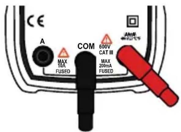
- Insert the black connector into the COM terminal; insert the red connector into A_mA VQ°C F terminal.
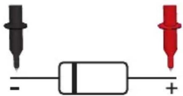
- Connect the tips to the semi-conductor component: the red to anode and the black to cathode.
natural_image
Simple electrical circuit diagram with battery, two black and red probes, and a plus sign (no text or symbols)Continuity testing

Be sure that the circuits have not energy and the capacitors are completely discharged to avoid hazard shock or damages in the equipment.
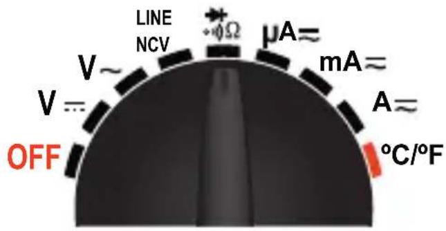
- Set the knob in the ⚙Ω position
- Press SEL until the icon appears in the top of the screen.
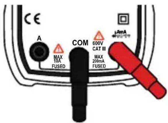
- Insert the black connector into the COM terminal; insert the red connector into terminal.
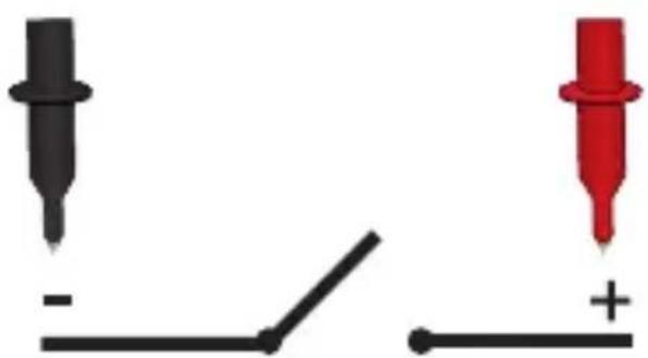
- Touch with the tips the circuit or wire that you want to check. The resistance value will shown in the screen, if the resistance is lower to 70 ± 30 , the signal will be audible.
natural_image
Two black and red test probes with a switch, no text or symbols presentTemperature measuring

To avoid shock hazard, do not measuring temperature if the input voltage exceed 36 V DC or 36 V AC RMS.
-
Set the knob in the °C / °F position
-
Press the SEL button to choose the unit measure:
°C = Centigrade
°F = Fahrenheit
-
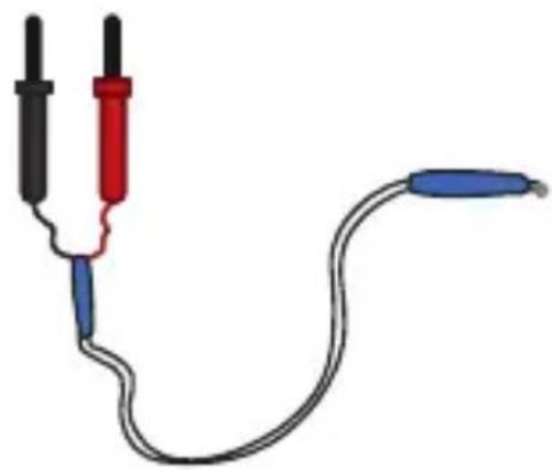
Insert the black temperature adapter into COM terminal, insert the red temperature adapter into A_mA V^^ terminal
-
Touch with the adapter the piece where you want to measure the temperature; keep the contact until the measure is stabilized.
natural_image
Illustration of a multimeter with three probes (black, red, blue) connected by a coiled wire, no text or symbols present.No-contact voltage detector (NCV)
-
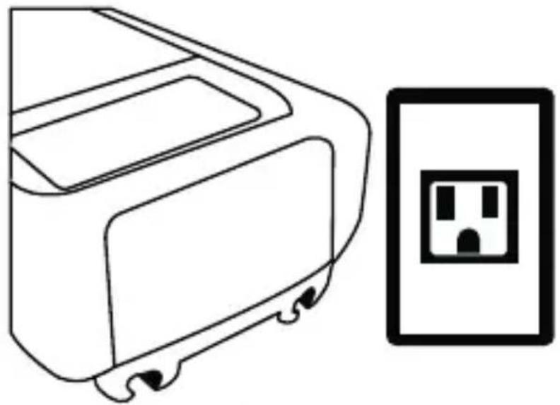
Set the knob in the NCV position.
-
Near the top of the multimeter to the equipment or component that you want to check (wire, contact, socket).
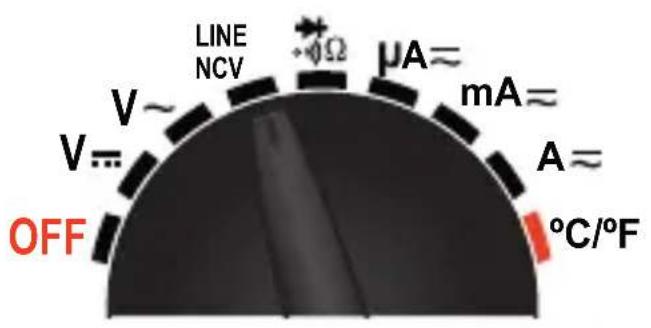
In case of voltage detection, the indicator LED will flash and the equipment will emit an audible signal
The circuit design, the insulation thickness and others variables may cause interference in the detection
The interference sources, as lanterns, engines may cause wrong detection
natural_image
Line drawing of a device with a separate electrical outlet symbol (no text or labels)MAINTENANCE
Fuse replacement

To avoid a shock hazard or damages to yourself or to multimeter, use only fuses with the same specifications (Fuse 1 10ABS1362, Fuse 2 200mABS1362).
1) Turn off the multimeter and disconnect the test cables.
2) Remove the rubber cover.
natural_image
Technical line drawing of a rectangular device with mounting points and internal components (no text or symbols)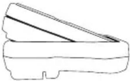
natural_image
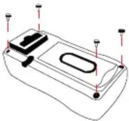
Simple line drawing of a mechanical component or tool (no text or symbols)3) Remove the screws.
4) Remove the cover.
5) Replace the fuses.
Fuse 1 Fuse
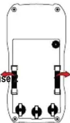
6) Set the screws and the cover again.
MEASURING SPECIFICATIONS
Direct current voltage
| Range Resolution Accuracy | |
| 200mV 100μV ±(0.5% reading + 2 digits) | |
| 2V 1mV ±(0.5% reading+ 3 digits) | |
| 20V 10mV | ±(0.8% reading+ 3 digits) |
| 200V 100mV | |
| 500V 1V ±(0.8% reading+ 5 digits) |
Overload protection: Range from 200 mV to 250 V DC or 250 V AC RMS
Other ranges: from 600V to 600V DC or AC RMS
Alternating current voltage
| Range Resolution Accuracy | |
| 2 V 1mV | |
| 20V 10mV | |
| 200V 0.1V | |
| 500V 1V | |
| 600V 1V |
Overload protection: 600 V DC or 600 V AC RMS
Other ranges: 40 Hz \~ 400Hz
DC Current
| Range Resolution Accuracy | |
| 200μA 0.1μA | |
| 2mA 1μA | |
| 20mA 10μA | |
| 200mA 100μA ±(20% reading + 5 digits) | |
| 2A 1mA | |
| 10A 10mA |
Overload protection: Fuse F200mA / 250V
Range without fuse 10 A
AC Current
| Range Resolution Accuracy | |
| 200μA 0.1μA | |
| 2mA 1μA | |
| 20mA 10μA | |
| 200mA 100μA ±(25% reading+ 5 digits) | |
| 2A 1mA | |
| 10A 10mA |
Overload protection: F200mA / 250V fuse
Range without fuse 10 A
Resistance
| Range Resolution Accuracy | ||
| 200Ω 0.1Ω | ±(1.0% reading+ 2 digits) | |
| 2kΩ 0.001kΩ | ||
| 20kΩ 0.01kΩ | ||
| 200kΩ 0.1kΩ | ||
| 2MΩ 0.001MkΩ | ||
| 20MΩ 0.01MΩ | ±(1.0% reading+ 2 digits) | |
Overload protection: 250 V DC or 250 V AC RMS
Maximum tension in open circuit: <3.2V
Diode and continuity
| Range Function | |
 | Diode approx voltage |
 | The function of the alarm will sound if the resistance is lower than 70Ω ± 30Ω |
Temperature
| Range Resolution Accuracy | |
| -20°C~750°C 1°C | |
| -4°F ~ 1832°F 1°F |
Overload protection: 250V DC or 250 V AC RMS
SPECIFICATIONS
Input: 3V --- (2 x AAA)
DC voltage range: 200 mV - 500 V
AC voltage range: 200 mV - 500 V
Resistance: 200-20 MΩ
AC Current range: 200 uA - 10 A
DC Current range: 200 uA - 10 A
Temperature range: -20 to 750 °C
Operating temperature: 0-40 °C
Storage temperature: -10 to 60 °C
Consumption: 0.1 mW / h
Standby power consumption: Not applicable
Specifications may change without notice

STEREN
Product: Digital Multi Meter With Auto Range Voltage Detector
Number part: MUL-282
Brand: Steren
This Steren product is warranted under normal usage against defects in workmanship and materials to the original purchaser for one year from the date of purchase.
CONDITIONS
- This warranty card with all the required information, invoice or purchase ticket, product box or package, and product, must be presented when warranty service is required.
- If the product is in the warranty time, the company will repair it free of charge.
- The repairing time will not exceed 30 natural days, from the day the claim was received.
- Steren sell parts, components, consumables and accessories to customer, as well as warranty service, at any of the addresses mentioned later.
THIS WARRANTY IS VOID IN THE NEXT CASES:
If the product has been damaged by an accident, acts of God, mishandling, leaky batteries, failure to follow enclosed instructions, improper repair by unauthorized personnel, improper safe keeping, among others.
a) The consumer can also claim the warranty service in the purchase establishment.
b) If you lose the warranty card, we can reissue it, if you show the invoice or purchase ticket.
RETAILER INFORMATION
Name of the retailer ____
Address
Product
Brand
Serial number ____
Date of delivery ____
CUSTOM SERVICE CENTER
01 800 500 9000
- Prueba de diodos
- MANTENIMIENTO
- MUL-282
- Digital Multimeter With Auto Range Voltage Detector
- CAUTIONS
- INDEX
- DESCRIPTION 29
- BATTERIES REPLACEMENT 33
- HOW TO USE 34
- MAINTENANCE 41
- MEASURING SPECIFICATIONS 42
- DESCRIPTION
- Parts
- Selector knob
- BATTERIES REMPLACEMENT
- HOW TO USE
- Voltage measuring
- Current measurement
- Diode test
- Continuity testing
- Temperature measuring
- No-contact voltage detector (NCV)
- MAINTENANCE
- Fuse replacement
- MEASURING SPECIFICATIONS
- Diode and continuity
- Temperature
- SPECIFICATIONS
- STEREN
- CONDITIONS
- RETAILER INFORMATION
Brand : Steren
Model : MUL-282
Category : Multimeter