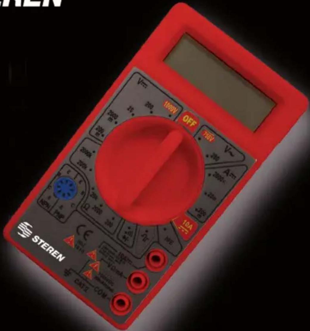
MUL-005 - Multimeter Steren - Free user manual and instructions
Find the device manual for free MUL-005 Steren in PDF.


| Product Type | Digital Multimeter |
| Model | MUL-005 |
| Display | 3 1/2 digits, polarity indicator |
| DC Voltage | Ranges: 200mV, 2000mV, 20V, 200V, 1000V; Accuracy: ±0.5% of reading + digits (200mV: +1 dgt, others: +3 dgt) |
| AC Voltage | Ranges: 200V, 750V; Accuracy: ±1.2% of reading + 10 digits; Frequency: 45-450Hz |
| DC Current | Ranges: 2000µA, 20mA, 200mA, 10A; Accuracy: ±1.0%-1.2% of reading + digits |
| Resistance | Ranges: 200Ω, 2kΩ, 20kΩ, 200kΩ, 2MΩ; Accuracy: ±1.2% of reading + 8 digits |
| Diode Test | Yes, displays forward voltage in mV |
| Continuity Test | Audible buzzer when resistance < 100Ω |
| Transistor Test | hFE measurement for NPN/PNP transistors, base current 10µA, VCE 2.8V |
| Power Supply | 9V battery (not included) |
| Fuse Protection | 200mA/250V fuse for current up to 200mA; 10A range unfused |
| Overload Protection | Up to 1000V DC / 750V AC on all ranges |
| Safety Rating | CAT II |
| Operating Temperature | 0°C to 50°C |
| Relative Humidity | < 75% |
| Warranty | 1 year |
| Input Jacks | COM, VΩmA, 10A |
| Transistor Socket | hFE test socket for small signal transistors |
Frequently Asked Questions - MUL-005 Steren
User questions about MUL-005 Steren
0 question about this device. Answer the ones you know or ask your own.
Ask a new question about this device
Download the instructions for your Multimeter in PDF format for free! Find your manual MUL-005 - Steren and take your electronic device back in hand. On this page are published all the documents necessary for the use of your device. MUL-005 by Steren.
USER MANUAL MUL-005 Steren
natural_image
Technician in blue hard hat and gloves working on electrical equipment with multimeter (no visible text or symbols)Modelo: MUL-005
Multímetro digital
natural_image
Pure electrical circuit symbol for a diode (no text or labels)STEREN PRODUCTO EMPACADO S.A. DE C.V.
Biólogo MaximIno Martínez No. 3408 Int. 3 y 4, San Salvador Xochimanca, México, D.F. 02870,
RFC: SPE941215H43
ELECTRONICA STEREN DEL CENTRO, S.A. DE C.V.
Rep. del Salvador 20 A y B, Centro, 06000, México. D.F. RFC: ESC9610259N4
ELECTRONICA STEREN DE GUADALAJARA, S.A.
López Cotilla No. 51, Centro, 44100, Guadalajara, Jal. RFC: ESG810511HT6
ELECTRONICA STEREN DE MONTERREY, S.A.
Colón 130 Pte., Centro, 64000, Monterrey, N.L. RFC: ESM830202MF8
ELECTRONICA STEREN DE TIJUANA, S.A. de C.V.
Calle 2a, Juárez 7636, Centro, 22000, Tijuana, B.C.N. RFC: EST980909NU5

natural_image
Technician in blue hard hat and gloves working on an electrical panel with multimeter (no visible text or symbols)Part number: MUL-005
Digital multimeter
User's Manual
V0309
IMPORTANT
Before using your new Digital multimeter, please read the following recommendations.
NEVER apply voltage or current that exceeds the maximum specifications of measurement in the multimeter.
CAUTION when you are working with high voltages.
DO NOT MEASURE voltages higher than 1000V in DC or 750V in AC
NEVER connect testing cables to a voltage source, when the switch is in one of next modes: Current, Resistance, or Test diode. Doing so may damage the meter
ALWAYS discharge the capacitors before measuring.
ALWAYS turn the mutilmeter off when is not in use.
FEATURES
• 3 1/2 digits digital display
- Polarity indicator
- Reading from logic signal
• Audible continuity
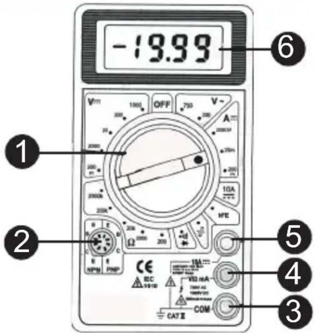
CONTROLS
1.- Selector switch.
2.- Testing transistors slot.
3.- COM jack Off.
4.- VΩmA input jack (AC/DC Voltage, resistance, logic signal, continuity, diodes and Current up 200mA)
5.- 10A jack.
6.- LCD screen.
ELECTRICAL SPECIFICATIONS
DC Voltage
| RangeResolutionAccuracy | ||
| 200m V 100uV | (+/-)(0,5% of reading q + 1 digits) | |
| 2000m V 1m V | (+/-)(0,5% of reading + 3 digits) | |
| 20V 10m V | ||
| 200V 100m V | ||
| 1000V 1V | ||
Overload protection: 220V AC for 200mV and 1000V DC for 750V AC for another ranges.
AC Voltage
| RangeResolutionAccuracy | ||
| 200V 100m V | (+/-)(1,2% of reading + 10 digits) | |
| 750V | 1V | |
Overload protection: 1000V DC or 750V AC for all ranges.
Frequency range: 45Hz a 450Hz
DC Current
| Range | ResolutionA | ccurac v |
| 2000uA 1uA | (+/-)( 1,0% of rading + 2 digits) | |
| 20mA 10uA | ||
| 200mA 100uA | (+/-)(1.2% of reading q + 5 digits) | |
| 10A 10mA | (+/-)(1.0% of rading + 2 digits ) |
Overload protection: 200mA/250V fuse (10A with no fuse) Measuring voltage drop: 200mV
Resistance
| RangeResol | utionAccuracy | |
| 200Ω | 100mΩ | (+/-)( 1,2% of reading + 8 digits) |
| 2kΩ | 1Ω | |
| 20kΩ | 10Ω | |
| 200kΩ | 100Ω | |
| 2MΩ | 1kΩ | |
Overload protection: 15 seconds maximum 220Vrms in all ranges.
Maximum open circuit voltage: 2.8V
INSTRUCTIONS
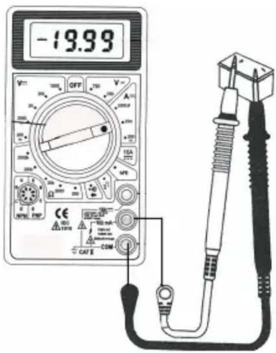
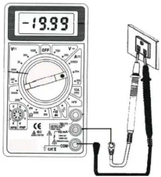
MEASURING DC / AC
1.- Connect the red testing point to the jack signaled "VΩmA" and the black testing point to the jack signaled "COM".
2.- Set the dial to the V = (VCD) / V\~ (VCA) setting When the value to be measured is unknown, set the dial to the maximum setting. Reduce level by level until reaching the desired one.
3.- Connect the testing points to the equipment to be measured.
4.- Turn the equipment to be measured on, the voltage will appear on the LCD display. The polarity will also appear.
V ---
V\~
ENGLISH-06
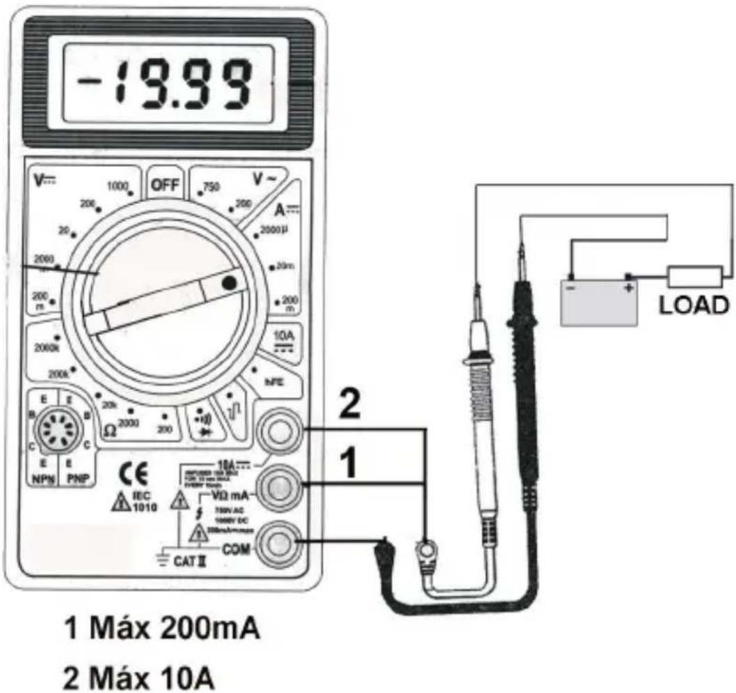
MEASURING DC AMPS
1.- Connect the red testing point to the jack signaled “VΩmA”, and the black testing point to the jack signaled “COM”. When measuring up to 200 mA connect the red testing point to the jack signaled “10A---” when measuring up to 10A.
2.- Set the dial to the A--- setting
3.- Open the circuit and connect the testing points (in serial) to the equipment to be measured.
4.- Read the value in the LCD display.
ENGLISH-07
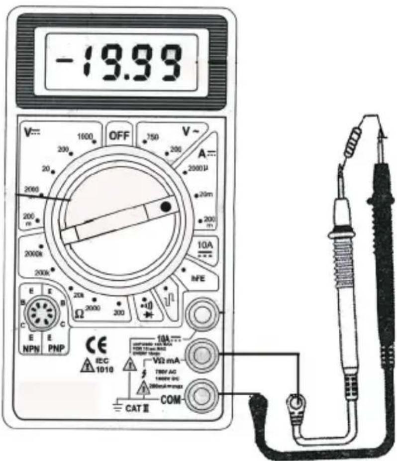
MEASURING RESISTANCE
1.- Connect the red testing point to the jack signaled "VΩmA" and the black testing point to the jack signaled "COM".
2.- Set the dial to Ohms (Ω) range.
3.- If the measured resistance is connected to a circuit, turn it off and discharge the capacitors before to measure.
4.- Connect the testing points to the resistance to be measured.
5.- The resistance value will appear in the LCD display.
ENGLISH-08
MEASURING DIODES
1.- Connect the red testing point in the jack signaled “VΩmA” and the black testing point in the jack signaled “COM”.
2.- Set the dial to the range.
3.- Connect the red testing point to the diode to be measured and the black testing point to the cathode.
4.- The voltage will appear in the LCD screen in m Volts.
MEASURING TRANSISTORS -hFE-
1.- Set the dial to hFE range.
2.- Determine if the transistor is NPN or PNP and localize the emitter, base, and collector.
If you don't know the configuration of the transistor, insert the transistor in hFE jack to show a data on the screen, the data shown is the hFE of the transistor and in that position will be the configuration from the transistor.
3.- The multimeter will show the approximate hFE value with base current condition of 10 uA and VCE 2.8 V.
MEASURING AUDIBLE CONTINUITY
1.- Connect the red testing point in the jack signaled "VΩmA" and the black testing point in the jack signaled "COM".
2.- Set the dial to the “)))” range.
3.- Connect the testing points on the circuit to be measured. If the resistance is less than 100 Ohms the multimeter will sound.
BATTERY AND FUSE REPLACEMENT
1.- Unscrew the battery compartment's cover and remove.
2.- Insert a 9V --- battery, pay attention to polarity also you can change the fuse.
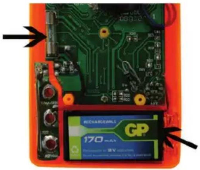
3.- Place again the cover and screw.
SPECIFICATIONS
Input: 9V --- (1 battery)
Resistance: 200 to 2Mohms +/- 1,2% accuracy
DC voltage: 200mV to 1000V +/- 0,5% accuracy
AC voltage: 200 to 750V +/- 1,2% accuracy
DC current: 2mA to 10A +/- 1 to 2%% accuracy
LCD screen: 3 1/2 digits, with polarity indicator.
Operating temperature: 0 to 50°C
Relative humidity < 75%
Product design and specifications are subject to change, without notice.
WARRANTY
This Steren product is warranted under normal usage against defects in workmanship and materials to the original purchaser for one year from the date of purchase.
CONDITIONS
1.- This warranty card with all the required information, invoice or purchase ticket, product box or package, and product, must be presented when warranty service is required.
2.- If the product stills on the warranty time, the company will repair it free of charge.
3.- The repairing time will not exceed 30 natural days, from the day the claim was received.
4.- Steren sell parts, components, consumables and accessories to customer, as well as
warranty service, at any of the addresses mentioned later.
THIS WARRANTY IS VOID IN THE NEXT CASES:
If the product has been damaged by an accident, acts of God, mishandling, leaky batteries, failure to follow enclosed instructions, improper repair by unauthorized personnel, improper safe keeping, among others.
a) The consumer can also claim the warranty service in the purchase establishment.
b) If you lose the warranty card, we can reissue it, if you show the invoice or purchase ticket.
- IMPORTANT
- FEATURES
- CONTROLS
- ELECTRICAL SPECIFICATIONS
- DC Current
- Resistance
- INSTRUCTIONS
- MEASURING DC / AC
- MEASURING DC AMPS
- MEASURING RESISTANCE
- MEASURING DIODES
- MEASURING TRANSISTORS -hFE-
- MEASURING AUDIBLE CONTINUITY
- BATTERY AND FUSE REPLACEMENT
- SPECIFICATIONS
- WARRANTY
- CONDITIONS
- THIS WARRANTY IS VOID IN THE NEXT CASES:
Brand : Steren
Model : MUL-005
Category : Multimeter