
MA15CPP2LP - Sorbet maker Marvel - Free user manual and instructions
Find the device manual for free MA15CPP2LP Marvel in PDF.


| Product Type | Clear Ice Machine |
| Brand | Marvel |
| Model | MA15CPP2LP |
| Dimensions (W x H x D) | 38,1 x 79,1-81,6 x 58,1 cm |
| Weight | 41 kg |
| Power Supply | 115 V, 15 A, 60 Hz, dedicated circuit |
| Ice Production Capacity | 17.7 kg/24h (normal mode), 13.2 kg/24h (ECO mode) |
| Storage Capacity | 15.8 kg |
| Ice Type | Clear ice cubes |
| Touch Screen | Yes, Intuit™ multifunction controls |
| Interior Lighting | IlluminICE™ LED Lighting |
| Energy Saving Mode | ECO (reduces production and consumption) |
| Delayed Start Function | Yes, from 1 to 8 hours or days |
| Control Lock | Yes |
| Cleaning Reminder | Every 6 months |
| Door Open Alert | After 5 minutes |
| Water Connection | Copper tubing 1/4", pressure 20-120 psi |
| Drainage Type | Gravity or pump (optional) |
| Recommended Ambient Temperature | 13-32 °C (built-in), 13-38 °C (freestanding) |
| Warranty | 1 year parts and labor, 5 years sealed system |
| Noise Level | Quiet (quietest on the market) |
| Soft-Close Door | Yes, patented soft-close system |
| Removable Decorative Panel | Yes (panel ready model) |
Frequently Asked Questions - MA15CPP2LP Marvel
User questions about MA15CPP2LP Marvel
0 question about this device. Answer the ones you know or ask your own.
Ask a new question about this device
Download the instructions for your Sorbet maker in PDF format for free! Find your manual MA15CPP2LP - Marvel and take your electronic device back in hand. On this page are published all the documents necessary for the use of your device. MA15CPP2LP by Marvel.
USER MANUAL MA15CPP2LP Marvel
EN Installation, Operation and Maintenance Instructions
Warranty registration 2
Safety information ....3
Unpacking your appliance ....3
Installing your appliance ....4
Cabinet clearances ....4
Leveling the appliance ....4
Electrical connection 5
Installing the drain plumbing 6
Gravity drain 6
Drain pump 7
Installing the water supply 8
Ice-maker operation 9
Product dimensions 12
Using your Electronic control 14
Starting your appliance 14
Turning your appliance "ON" or "OFF" 14
Controllock....15
Door ajar alarm....15
Error codes 15
Delay start / Vacation mode 15
Clean reminder 15
Options menu 16
Normal and eco mode 16
Cleaning your ice machine 16
Clean mode 16
Overlay door panel installation ....19
Care and cleaning 23
Energy saving tips 23
Obtaining service 24
Troubleshooting the ice machine 25
Preparing the ice machine for storage .....27
Drain pump removal 29
Warranty 31
Welcome
Congratulations on your purchase of the industry's quietest clear ice machine with the best ice clarity and purity. Your new investment is protected by a limited warranty for the first year, and hermetically sealed refrigeration system parts are covered for an additional 4 years.

Here's your guide to the operation and maintenance of your Marvel Clear Ice Machine to ensure years of enjoyment. If you have any questions, please contact Marvel Customer Service or Tech Support at:
Phone: (800) 223-3900
Email:
- Customer Service: orderdesk@agamarvel.com
• Tech Support: techsupport@agamarvel.com
Warranty Registration:
We encourage all new ice machine owners to take a moment to register their product for a more tailored experience should you need support from us in the future. It's recommended to send in your warranty registration card immediately after taking delivery of your appliance.
To Register:
- Mail in your warranty registration card or register online at marvelrefrigeration.com
• The following fields are required:
• Service Number
- Serial Number
- Date of Purchase
- Dealer Name and Address
- The service number and serial number can be found on the serial plate located on the inside of the cabinet on the left side (See Figure 1).
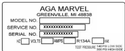
Figure 1
About your Marvel clear ice machine:
Performance
- The quietest ice machine you can buy.
- New energy-saving options to conserve water and energy.
- Engineered to consistently produce pure, clear ice with unrivaled clarity and slower melt.
• Produces up to 39 pounds of clear ice daily. - Close Door Assist System™ prevents energy loss by automatically drawing door to a gentle close.
Storage Capabilities
- Stores 35 pounds of clear ice in thermo-insulated ice bin.
- Sleek scoop design is positioned for easy reach.
- Easy-to-clean, hygienic interior surface.
Touchscreen Controls
- Multifunction Marvel Intuit™ Integrated Controls
- Eco Ice™, Delayed Start and Vacation mode adapts ice production to usage.
- Audible alerts and programmed cleaning reminders.
Aesthetics
- New IlluminICE™ feature projects LED lighting through clear ice for a dazzling illumination effect.
- Designer handle and white interior.
- Easy-to-install panel-ready option.
- 4" black adjustable toe kick.
- Height adjustment up to 1" with leveling legs.



Important Safety Instructions
Warnings and safety instructions appearing in this guide are not meant to cover all possible conditions and situations that may occur. Common sense, caution, and care must be exercised when installing, maintaining, or operating this appliance.
Recognize Safety Symbols, Words, and Labels.

WARNING
WARNING - You can be killed or seriously injured if you do not follow these instructions.

CAUTION
CAUTION-Hazards or unsafe practices which could result in personal injury or property / product damage.
NOTE
NOTE-Important information to help assure a problem free installation and operation.

WARNING
State of California Proposition 65 Warning:
This product contains one or more chemicals known to the State of California to cause cancer.

WARNING
State of California Proposition 65 Warning:
This product contains one or more chemicals known to the State of California to cause birth defects or other reproductive harm..
AGA MARVELis committed to building a quality product in an environmentally friendly manner. Our processes are tightly controlled and closely monitored. We have achieved certifications in ISO 9001 for quality assurance, ISO 14001 for environmental management, and OHSAS 18001 for occupational health and safety from Lloyd's Register Quality Assurance.

WARNING
EXCESSIVE WEIGHT HAZARD
Use two or more people to move product. Failure to do so can result in personal injury.
Remove Interior Packaging
Your appliance has been packed for shipment with all parts that could be damaged by movement securely fastened. Remove internal packing materials and any tape holding internal components in place. The owners manual is shipped inside the product in a plastic bag along with the warranty registration card, and other accessory items.
Important
Keep your carton and packaging until your appliance has been thoroughly inspected and found to be in good condition. If there is damage, the packaging will be needed as proof of damage in transit. Afterwards please dispose of all items responsibly.

WARNING
Dispose of the plastic bags which can be a suffocation hazard.
Note to Customer
This merchandise was carefully packed and thoroughly inspected before leaving our plant. Responsibility for its safe delivery was assumed by the retailer upon acceptance of the shipment. Claims for loss or damage sustained in transit must be made to the retailer.
NOTE
DO NOT RETURN DAMAGED MERCHANDISE TO THE MANUFACTURER - FILE THE CLAIM WITH THE RETAILER.

CAUTION
If the appliance was shipped, handled, or stored in other than an upright position for any period of time, allow the appliance to sit upright for a period of at least 24 hours before plugging in. This will assure oil returns to the compressor. Plugging the appliance in immediately may cause damage to internal parts.

WARNING
WARNING - Help Prevent Tragedies
Child entrapment and suffocation are not problems of the past. Junked or abandoned refrigerators are still dangerous - even if they sit out for "just a few hours".
If you are getting rid of your old refrigerator, please follow the instructions below to help prevent accidents.
Before you throw away your old refrigerator or freezer:
• Take off the doors or remove the drawers.
- Leave the shelves in place so children may not easily climb inside.
Select Location
The proper location will ensure peak performance of your appliance. We recommend a location where the ice machine will be out of direct sunlight and away from heat sources. To ensure your product performs to specifications, the recommended installation location temperature range is from 55 to 90°F (13 to 32°C) for built in ice machines and 55 to 100°F (13 to 38°C) for freestanding ice machines. Ice machines will not perform correctly in ambient temperatures less than 55°F (13°C).
Cabinet Clearance
Ventilation is required from the bottom front of the appliance. Keep this area open and clear of any obstructions. Adjacent cabinets and counter top can be installed around the appliance as long as the front grille remains unobstructed.

CAUTION
Front Grille
Do not obstruct the front grille. The openings within the front grille allow air to flow through the condenser heat exchanger. Restrictions to this air flow will result in increased energy usage, loss of cooling capacity and low ice production. For this reason it is important this area not be obstructed and the grille openings kept clean. AGA MARVEL does not recommend the use of a custom made grille as air flow may be restricted. (See Figure 2).
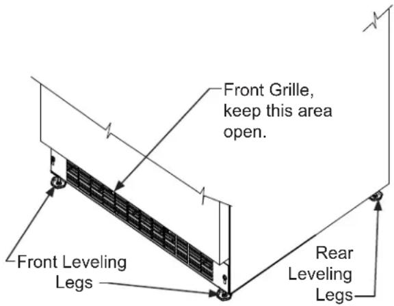
Figure 2
Leveling Legs
Adjustable legs at the front and rear corners of the appliance should be set so the unit is firmly positioned on the floor and level from side to side and front to back. The overall height of your Marvel appliance may be adjusted between the minimum, 31 ^1/8 " (79.1 cm), by turning the leveling leg in) and the maximum, 32 ^1/8 " (81.6 cm) by turning the leveling leg out).
To adjust the leveling legs, place the appliance on a solid surface and protect the floor beneath the legs to avoid scratching the floor. With the assistance of another person, lean the appliance back to access the front leveling legs. Raise or lower the legs to the required dimension by turning the legs. Repeat this process for the rear by tilting the appliance forward using caution. On a level surface check the appliance for levelness and adjust accordingly.
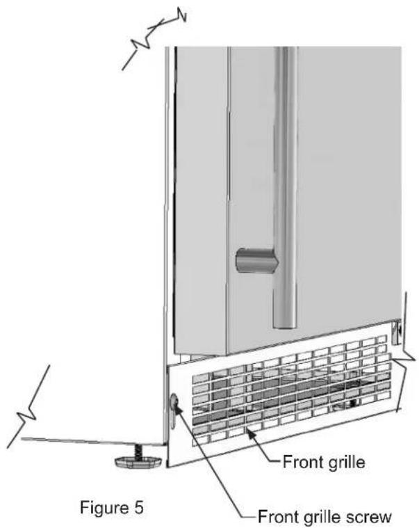
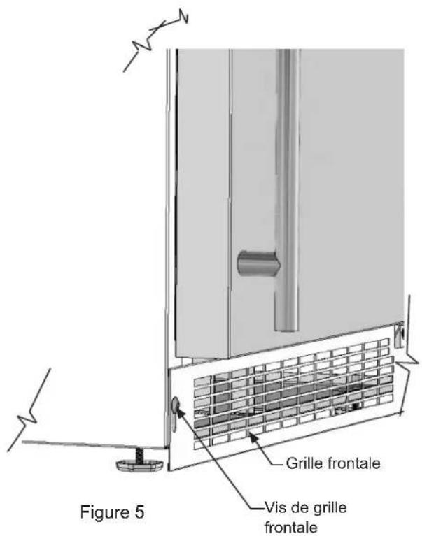
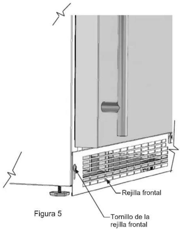
The front grille screws may be loosened to raise or lower the grille to the desired height. When adjustment is complete tighten the two front grille screws. (See Figure 5).
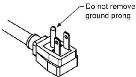
Figure 3
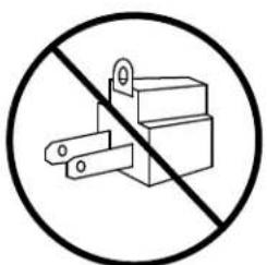
Figure 4
WARNING
Electrical Shock Hazard
- Do not use an extension cord with this appliance. They can be hazardous and can degrade product performance.
- This appliance should not, under any circumstances, be installed to an un-grounded electrical supply.
- Do not remove the grounding prong from the power cord. (See Figure 3).
- Do not use an adapter. (See Figure 4).
- Do not splash or spray water from a hose on the appliance. Doing so may cause an electrical shock, which may result in severe injury or death.
Electrical Connection
A grounded 115 volt, 15 amp dedicated circuit is required.
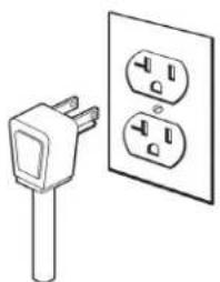
This product is factory equipped with a power supply cord that has a three-pronged, grounded plug. It must be plugged into a mating grounding type receptacle in accordance with the National Electrical Code and applicable local codes and ordinances (see Figure 6). If the circuit does not have a grounding type receptacle, it is the responsibility and obligation of the customer to provide the proper power supply. The third ground prong should not, under any circumstances, be cut or removed.
natural_image
Illustration of a power plug and two separate electrical socket (no text or symbols)Figure 6
NOTE
Ground Fault Circuit Interrupters (GFCI) are prone to nuisance tripping which will cause the appliance to shut down. GFCI's are generally not used on circuits with power equipment that must run unattended for long periods of time, unless required to meet local building codes and ordinances.

CAUTION
Failure to use an adequate drainage system, will result in surrounding water damage and/or poor ice production.

WARNING
Electrical Shock Hazard
Reasonable care and safe methods should be practiced. Do NOT work with energized electrical equipment in a wet area. Read and follow the installation instructions listed in this manual.
Drain Plumbing
Your ice machine requires drain plumbing. There are 2 variations of ice machines in regards to the installation of the drain plumbing, without a drain pump (gravity drain), and with a drain pump.
Gravity Drain (no drain pump):
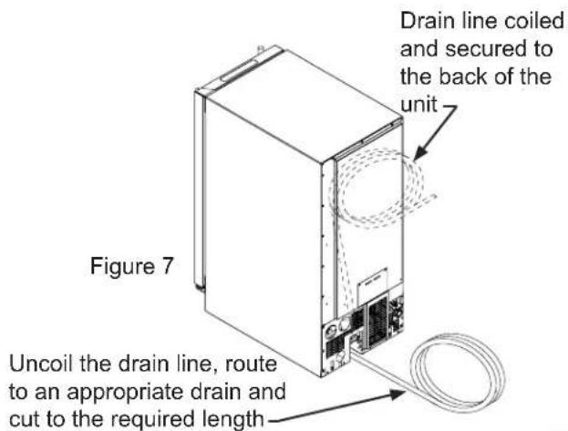
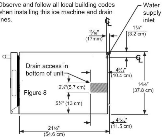
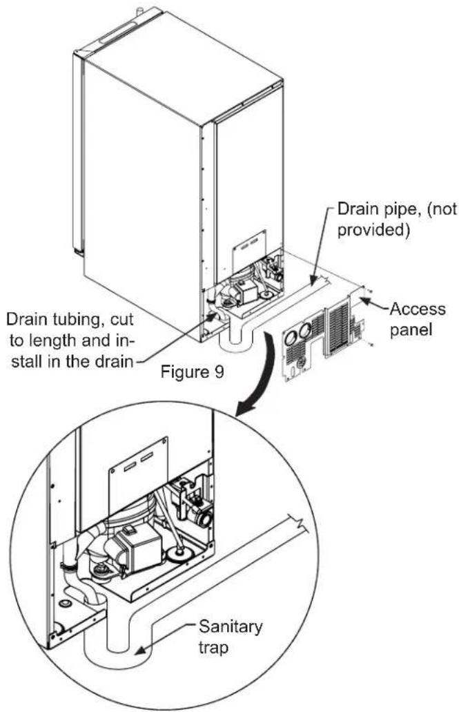
The ice machine is shipped with the drain line installed, coiled and secured to the back of the cabinet as shown in Figure 7. It can be uncoiled, routed to an appropriate drain and cut to length as required. Additionally there is the provision of drain routing through the cut-out in the bottom of the unit, (see the gray area in Figure 8). A drain can be installed in this gray area with the drain line cut to a short length and positioned into the drain as shown in Figure 9, or if the ice machine is to be built-in, the drain tube could be routed through a hole in the floor in this gray area to a drain below.

CAUTION
The gravity drain line must be routed no higher than 6" (15.2 cm) off the floor to assure proper drainage.

CAUTION
Observe and follow all local building codes when installing this ice machine and drain lines.
With a factory installed drain pump:
The Marvel Drain Pump is designed to remove drain water from ice machines installed in areas without direct drainage access. The sealed reservoir pump collects the melted ice water and pumps it to a maximum lift of eight (8) feet (2.44 meters) using no more than the 20 feet of 38 " I.D. vinyl tubing.
If the ice machine has a factory installed drain pump. Discharge tubing is coiled up and attached to the back of the ice machine. The 38 inch I.D. tubing needs to be plumbed and connected to a sanitary sewer. Refer to Figure 10.

CAUTION
This drain pump is designed to be installed in Marvel ice machines only and is approved for use with water only.

WARNING
Electrical Shock Hazard
Risk of electrical shock or personal injury could occur due to moving components, if the machine compartment access cover is removed before unplugging the ice machine power cord.
Optional Drain Pump.
An optional drain pump is available if you have purchased an ice machine without one and do not have access to a gravity drain. Installation instructions are provided with the optional drain pump. Contact AGA Marvel customer service at 800-223-3900 or your dealer for ordering.
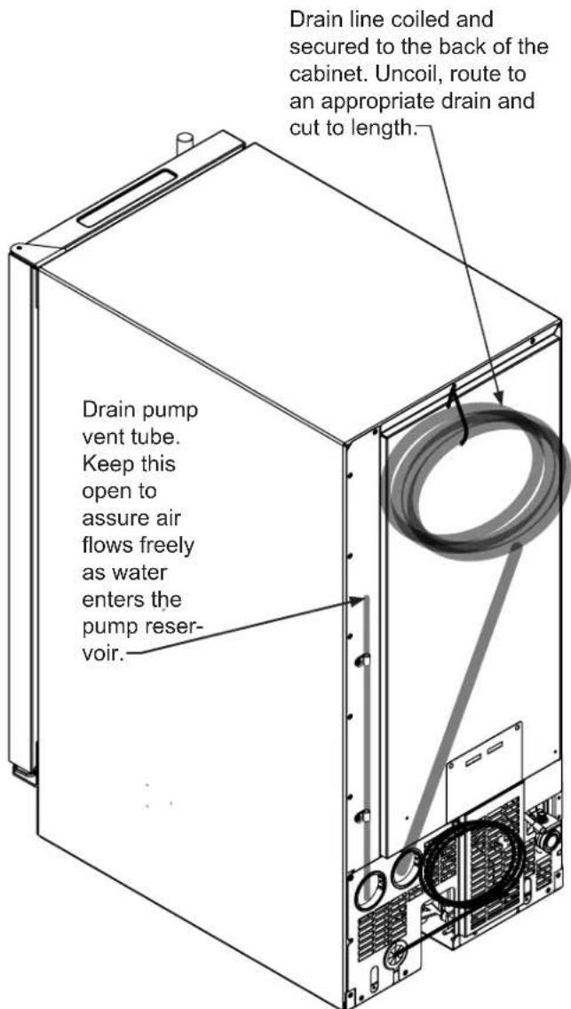
Figure 10
Water Supply

CAUTION
Observe and follow all local building codes when installing this appliance.
This ice machine must be connected to a potable cold water supply line. delivering water pressure between a minimum of 20 psi and a maximum of 120 psi.
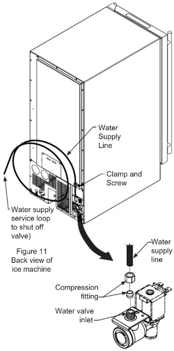
Use 14 " copper tubing for your water supply which is available at any local hardware or plumbing supply store. Route the 14 " copper tubing to suit your installation being sure not to kink the tubing. Purchase enough copper tubing length to allow a coil to be formed behind the unit for a "service loop" which will allow the appliance to be pulled out from the installation for servicing or cleaning. (See Figure 11). Connect the copper tubing to the "top side" of a cold water pipe to prevent the ice-maker from plugging with sediment.
A shutoff valve is recommended on the water supply line to ease servicing the appliance. NOTE: A SELF-PIERCING TYPE VALVE IS NOT RECOMMENDED as they are prone to clogging with sediment which will create pressure drop reducing the water supply to the unit.
Connect the copper tubing water supply to the water valve inlet with the compression nut fitting provided.
IMPORTANT: Secure the water supply line to the back of the cabinet with the screw and strain relief clamp provided in the corner of the back panel. (See Figure 11).
Make certain all connections are watertight after installation. Form the tubing so that it will not vibrate against the cabinet body or kink when your appliance is moved in and out of position.
This ice machine is designed to make clear ice from the majority of water sources on a daily basis. If your results are unsatisfactory, your water may need to be filtered or treated. A water specialist can recommend proper water treatment.

CAUTION
To prevent water leaks:
- The water line fitting is to be used with copper tubing only. Do not use with plastic tubing.
- Do not use any thread sealers on this water line fitting.
NOTE
Reverse osmosis, (RO), water, softened water, and deionized water are not recommended as they can adversely affect the quality and quantity of the ice.
The Ice Making Process
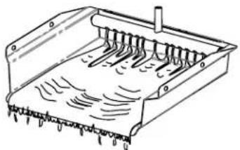
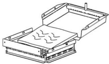
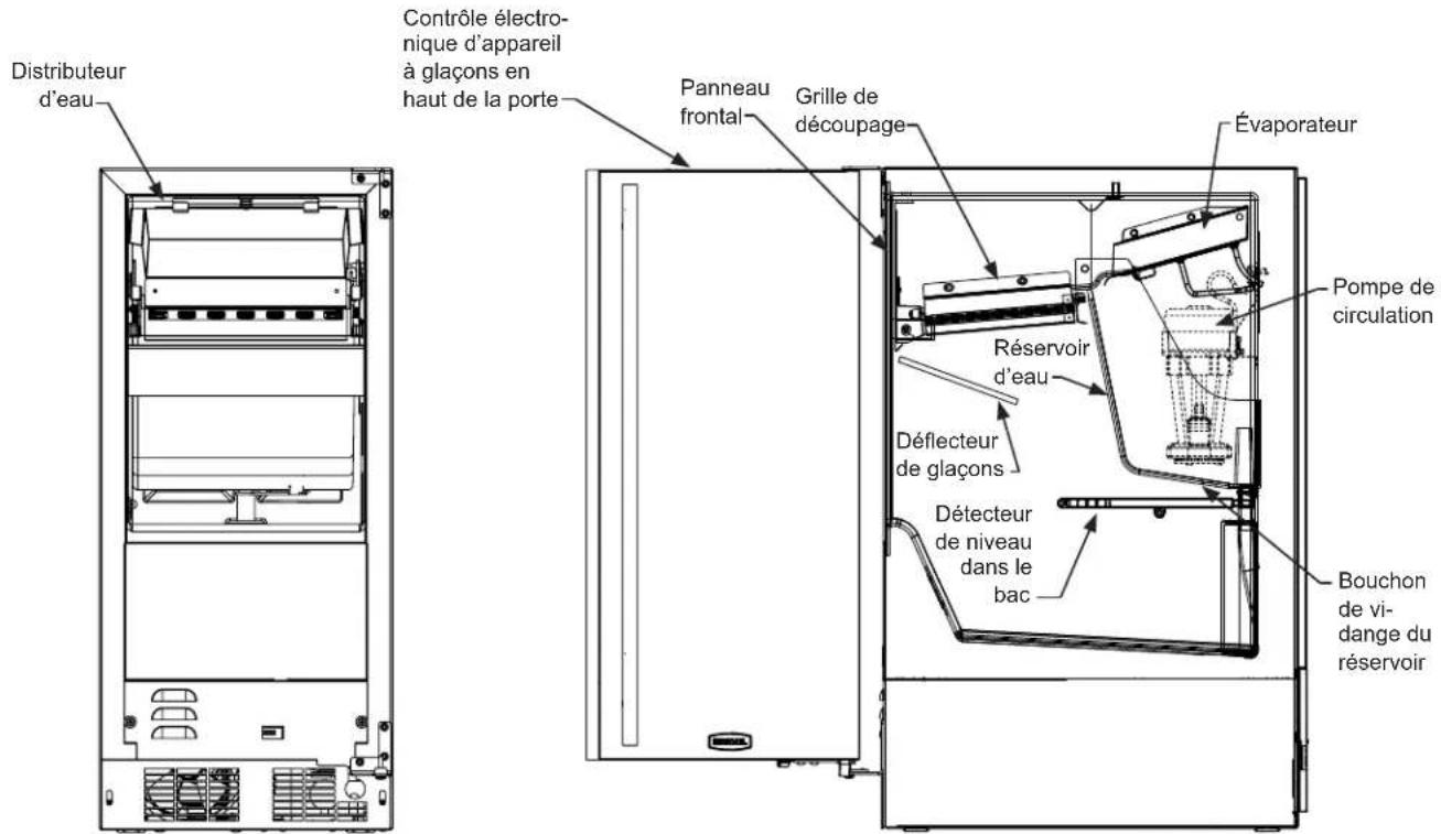
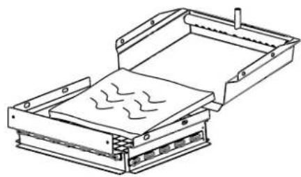
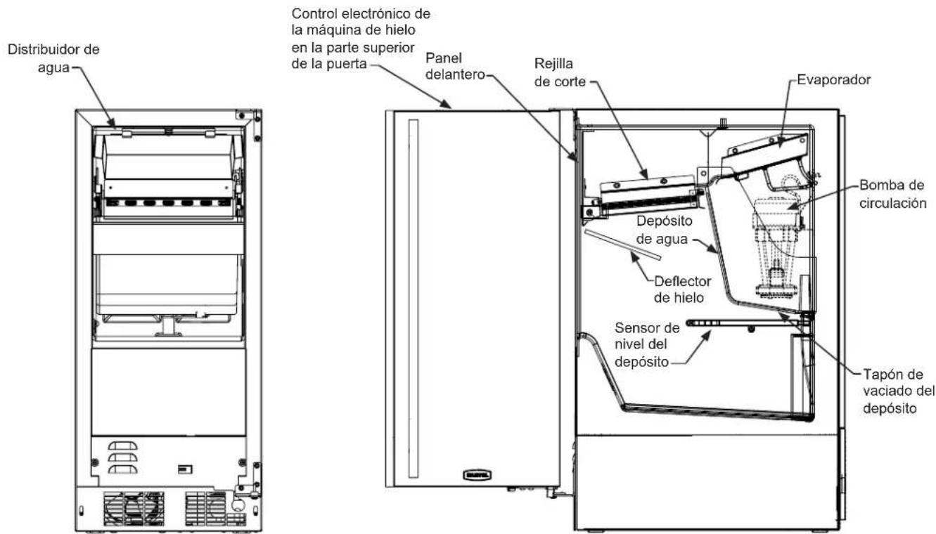
Your ice machine is unique in how it forms ice with fractional freezing to form a slab of ice that is clear and has less dissolved solids than the water it is produced from. This is accomplished by running water over the cold evaporator plate (see Figure 12) which gradually freezes the water to produce the ice slab. Pure water freezes first, leaving the dissolved solids in the residual reservoir water to provide clear ice.
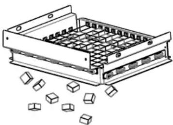
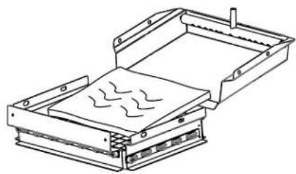
When the ice slab reaches the correct thickness, the ice sheet is released and slides onto the grid cutter (see Figure 14). Here, the ice slab is cut into squares by the grid cutter's heated wires (see Figure 15). The water containing the dissolved minerals is drained after each freezing cycle. Fresh water enters the machine for the next ice making cycle.
natural_image
Technical line drawing of a mechanical component with grooves and internal channels (no text or symbols)Figure 12
natural_image
Technical line drawing of a mechanical device with internal components and no visible text or symbolsFigure 14
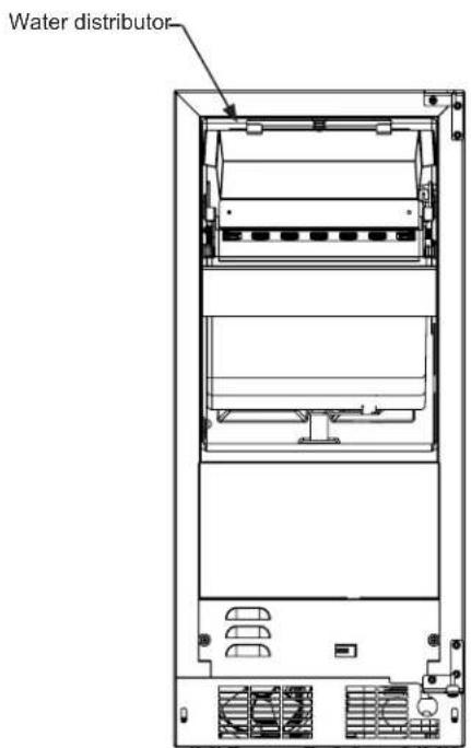
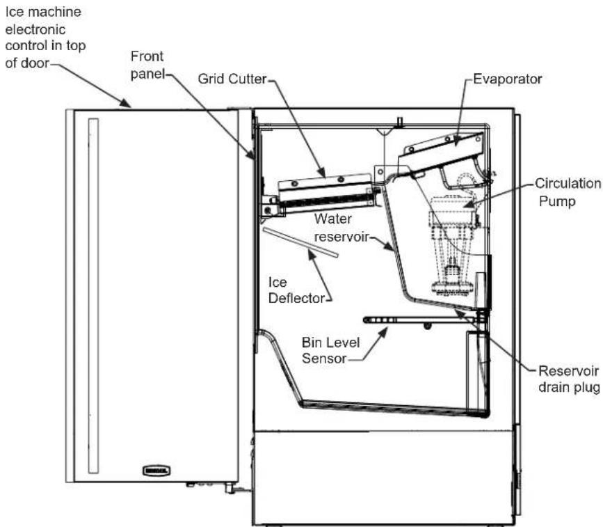
Figure 13
The ice machine will keep producing ice until the ice machine's bin is full and will restart automatically when ice needs to be replenished in the bin. The ice bin is not refrigerated, and some melting will occur by design to preserve the ice quality and clarity. Allow your ice machine to run for 24-48 hours to accumulate ice in the ice machine's bin.
natural_image
Technical line drawing of a mechanical component with internal grid structure and scattered 3D cubes (no text or symbols)Figure 15
The bin level sensor is located in the ice bin, it senses when the ice supply is low or full and starts or stops the ice making process accordingly.
NOTE
If the water supply is turned off to the ice machine be sure to set the electronic control to the "OFF" position or remove power to the unit.
Ice Production
In normal mode the ice machine will produce up to 39 pounds (17.7 kg) of clear ice in a 24-hour period when installed in a 72°F ambient with a 55°F water supply. In "ECO" mode (see page 16) the ice machine will produce up to 29 pounds (13.2 kg) of clear ice in the 24 hour period.
NOTE
“Initial” ice production and ice accumulated in the storage bin will vary significantly. This is normal. During the first 24-hours of operation the unit will produce up to 39 lbs of ice at the above ambient and water temperature conditions, but when starting with an empty ice storage bin, the storage bin may only accumulate up to 18 lbs of ice. By design, the ice storage bin is maintained at a temperature slightly above freezing to allow the stored ice to slowly melt, to preserve the ice quality and clarity and assure a constant supply of fresh ice. As ice is accumulated in the bin, the ice production rate will overcome the ice melt and the storage bin will fill to capacity.
New Sounds
The ice machine will make sounds that are different than your household refrigerator. Because these sounds are new to you they may be of a concern but are most likely normal. The ice production process will make noises that are not typical in a refrigeration product, ice falling onto hard surfaces, water cascading across the evaporator, and valves opening and closing. Following are some of the sounds that you may hear:
A buzzing sound will be heard when the water valve opens to fill the water reservoir.
A rattling noise which could be water flowing through the water line.
A splashing sound when water is flowing over the evaporator plate and into the water reservoir.
A "thud" when the ice slab is released from the evaporator plate and slides onto the grid cutter.
"Clicks" when the cubes fall into the ice storage bin.
A gurgling sound which is refrigerant flowing in the ice machine.
An air noise from the condenser fan.
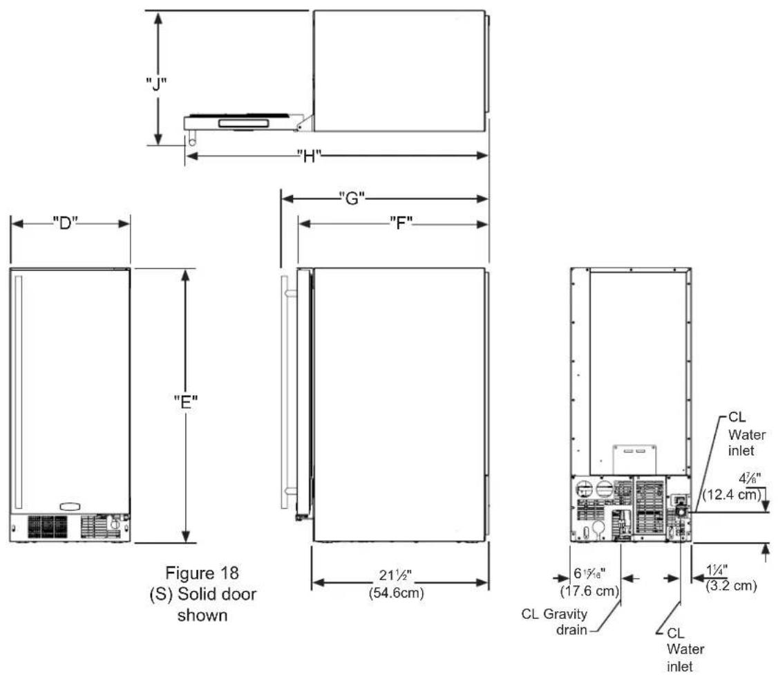
| ROUGH-IN OPENING DIMENSIONS CABINET DIMENSIONS | |||||||||
| MODEL | "A" | "B" | "C" | "D" | "E" | "F" | "G" | "H" | "J" |
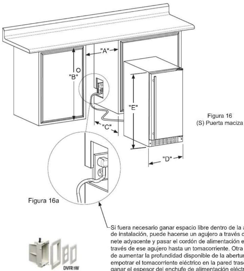
| MA15C*S | 15"(38.1 cm) | **31 18 " to 32 18 " (79.7 to 82.2 cm) | 24"(61 cm) | 14 18 " (37.8 cm) | 31 18 " to 32 18 " (79.1 to 81.6 cm) | 23 18 " (60 cm) | 25 12 " (64.8 cm) | 37 116 " (95.4 cm) | 16 115 " (42.1 cm) |
| MA15C*P | 15"(38.1 cm) | **31 38 " to 32 38 " (79.7 to 82.2 cm) | *24"(61 cm) | 14 18 " (37.8 cm) | 31 18 " to 32 18 " (79.1 to 81.6 cm) | 22 78 " (58.1 cm) | - | 37 116 " (95.4 cm) | 13 78 " (35.3 cm) |

| DOOR STYLE |
| (S) Solid Door |
| (P) Solid Overlay Door (no handle) |
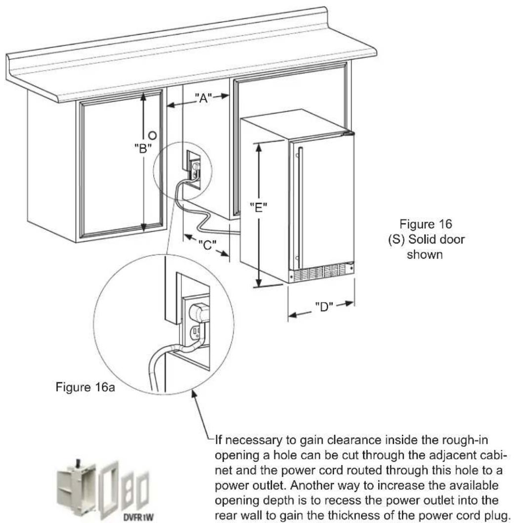
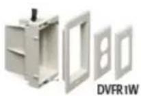
Figure 17
-If necessary to gain clearance inside the rough-in opening a hole can be cut through the adjacent cabinet and the power cord routed through this hole to a power outlet. Another way to increase the available opening depth is to recess the power outlet into the rear wall to gain the thickness of the power cord plug. Not all recessed outlet boxes will work for this application as they are too narrow, but a recessed outlet box equivalent to Arlington #DVFR1W is recommended for this application, (see Figure 17).
| PRODUCT DATA | ||
| MODEL | ELECTRICAL REQUIREMENTS # | PRODUCT WEIGHT |
| MA15C*S | 15V/60Hz/15A | 100 lbs(45.5 kg) |
| MA15C*P | 15V/60Hz/15A | 100 lbs(45.5 kg) |
* To install MA15C*P model with the door face flush with the adjacent cabinet doors, custom decorative panel thickness cannot exceed 34'' (19 mm).
** Minimum rough-in opening required is to be larger than the adjusted height of the cabinet.
# A grounded 15 amp dedicated circuit is required. Follow all local building codes when installing electrical and appliance.
On/off Menu Display area Delay timer Lock





Figure 19
User interface display
Display icons:

"ON/OFF" icon : used for turning the appliance on and off.

"MENU" icon : used to access optional functions in the user interface.

"Clock" icon : used to enter the Delay start/vacation mode.

"LOCK" icon : used to lock out functions in the user interface.
Display area text:
ICE
Signifies the appliance is on and producing ice.
ECO
Signifies the appliance is in economical ice production mode.
OFF
Signifies the appliance is off
DOOR
Signifies a door ajar alarm condition.
CLEAN
Cleaning is recommended or the appliance is in the clean mode.
Delay start/Vacation mode:


- When lit, this signifies the delay start/vacation mode is operational.
NOTE
The control display is covered with a clear plastic protective film. This film may be removed by carefully lifting at a corner.
Starting your clear ice machine:
ICE
Plug the ice machine into a 115 volt wall outlet, (see page 5 for electrical information). Your appliance is shipped from the factory in the "ICE" mode and will begin start-up of ice production after the start-up routine.
Upon applying power to the unit, or after a power interruption, the Ice machine will perform a self-test, followed by a harvest cycle to clear any in-process ice production. This start-up routine, (“after power is applied to the unit”), takes approximately 13 minutes to complete before an ice production cycle starts.
If the appliance does not start, confirm the wall outlet has power, and the control is in the "ICE" mode, (see Options section below). Do not start the ice machine in "ECO" mode. "ECO" mode should only be used after there is a full bin of ice.
Turning your ice machine On and Off:
ICE
If your appliance is on, "ICE" will be displayed. To turn the appliance off, push and hold the "ON/OFF" icon for 3-seconds. The display will show "OFF".

NOTE
OFF
When turned off, the ice machine will complete its current ice production cycle then shut off.

The drain pump (if equipped) and the interior light will still be functioning during the OFF mode. To turn the appliance back on, press and hold the "ON/OFF" icon for 3-seconds, the display will show "ICE".
ICE

WARNING
Turning the ice machine "OFF" will only terminate the ice production, it does not remove power from the appliance. Always unplug the power cord from the wall outlet before servicing the unit.
Control Lock:
The user interface can be locked to avoid unintentional changes from things like cleaning. To lock the appliance, push and hold the "LOCK" icon for 5-seconds. The "LOCK" icon will flash 3 times, then change to steady back-lit. To unlock the user interface, press and hold the "LOCK" icon for 5-seconds, and the back-light will turn off.
NOTE
The "LOCK" icon is the only active key in this mode. If other icons are pressed while in the lock mode the "LOCK" icon will flash 3 times, and an audible tone will sound, to remind the user the appliance is in the lock mode.
Door ajar alarm:
If the door is open, or not closed properly for 5 minutes the "DOOR" indicator will illuminate and flash and an audible tone will sound. The audible alarm can be muted by pressing the "Lock" keypad. This alarm condition can be reset by closing the door or momentarily pressing the "ON/OFF" icon, (i.e.-if you are cleaning the storage compartment, etc.). The alarm will recur in 5 minutes if the alarm condition persists.
Error codes:
The ice machine is monitored continuously. Any OPEN or SHORTED circuit condition with a temperature sensor or miscommunications between the control and user interface will initiate an ERROR CODE as listed below:
Delay start/Vacation mode:
Your ice machine is equipped with a delay start function. This feature can be used to temporarily shut the appliance off for 1, 4, 6, or 8 hours or days. Upon completion of the selected delay period, the appliance will resume operation. This is ideal for temporarily stopping ice machine noises or to save water and electricity if you are away from home but want fresh ice upon your return.
To enter the delay start mode, press the "CLOCK" icon while the appliance is in "ICE" mode. This will delay the next harvest by the time displayed. Each additional press of the "CLOCK" icon will add time, from 1, 4, 6, or 8 hours, to 1, 4, 6, or 8 days. The next press after 8 days will leave delay set mode. After the desired time has been selected, press the "ON/OFF" icon for 2 seconds to accept, your unit will shut off and a clock icon and your selected time will be displayed. When the selected time has elapsed, normal ice production will resume.

hours days



To cancel the delayed start, press and hold the "ON/OFF" icon until the appliance enters OFF, then press and hold the "ON/OFF" icon again until the appliance enters "ICE" mode.




Clean reminder:
A "CLEAN" reminder will occur every 6 months to remind you that it may be time to clean your appliance. Over time mineral build up on the cold evaporator plate can occur which can adversely affect the quality of your ice. This build-up is dependent on your water source and usage. Normal ice production will continue while the "CLEAN" reminder played. You may clear the "CLEAN" reminder at any by momentarily pressing the "ON/OFF" icon. When I am the "CLEAN" reminder will reset and not occur for an 6 months. If you choose to clean the appliance at this see the options menu section below.


| Error Codes | |||
| Error Displayed Code Error Description Action to Take | |||
| Bin Sensor error | "OFF" will flash continuously in 1 second intervals in the display. No audible alarm will sound. | Failed temperature sensor. Machine operation will immediately enter an OFF state. | Call service to have the temperature sensor replaced. |
| System Sensor error | "ICE" will flash continuously in the display. No audible alarm will sound. | Failed condenser temperature sensor. Machine operation will continue but ice production cycle will not adapt to varying ambient conditions, so ice quality may vary. | Call service to have the temperature sensor replaced. |
| Communication error | Continual flashing of all indicators on the display. | Loss of communication between the main board and the user interface. | Call service to have a diagnostic check. |
Options menu:

Normal and ECO mode:
Your ice machine comes with an optional "ECO" mode. While in this mode ice production will slow and the appliance will use less water and electricity. "ECO" mode should only be initiated after there is a full bin of ice. To enter "ECO" mode do the following:
- Press the "MENU" icon twice and the green "ECO" will flash.
- Press and hold the "ON/OFF" icon until the green "ECO" stops flashing and remains illuminated.
- To return to the standard operating rate press the "MENU" icon twice, the ECO will turn off and the "ICE" will be flashing. Press and hold the "ON/OFF" icon until the "ICE" stops flashing and remains illuminated.




Clean mode:
To ensure maximum performance and ice quality, it is recommended to clean your ice machine once every six months.

CAUTION
Use only approved ice machine cleaners and be sure to follow all label warnings and directions. Incorrect chemical usage, and any damage or injury that may result, is not covered by warranty.
NOTE
For reference see our "Care and Cleaning video" at the website: www.marvelrefrigeration.com.
To clean your ice machine you will need to purchase a "nickel safe" ice maker cleaner. Cleaner can be obtained by contacting AGA Marvel customer service at 800-223-3900 or are available at most appliance retailers or through the cleaners website. Several recommended cleaners are listed below:
• Kirby's Certified ice machine cleaner. 100% nickel safe.
• Nu-Calgon nickel safe ice machine cleaner.
- Franklin Machine Products Nickel safe ice machine cleaner.
Once you have your cleaner:
Turn the ice machine off by pressing and holding the "ON/OFF" icon for 3 seconds. "OFF" will be displayed on the control.

OFF
Follow the following three step procedure for removing the grid cutter cover from the ice machine, Refer to Figures 22 and 23:
①-pull out on this corner first to remove the cover corner from the mounting peg.
②-pull out on this corner next to remove it from the mounting peg.
③-reach behind cover and push cover towards you to remove cover from the center mounting peg.
Remove all ice from the ice bin, (see Figure 23).
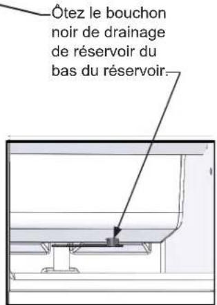
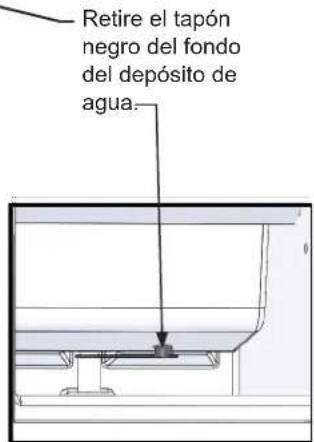
Drain the water from the water reservoir, by removing the black plug from the bottom of the fresh water reservoir. (See Figure 24). After the water is drained replace the plug in the bottom of the reservoir.
Allow all of the ice to fall from the evaporator plate and remove any ice from the grid cutter. If there is ice embedded in the grid cutter wires, wait for it to melt and fall out. Do not try to remove ice that is embedded in the grid cutter wires as that may break the wires. (See Figures 20 and 21).

CAUTION
Forcing ice through the grid cutter will break the grid cutter wires.
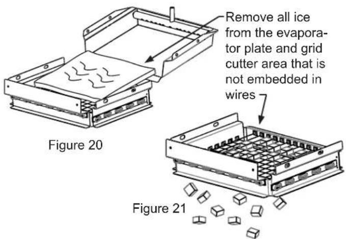
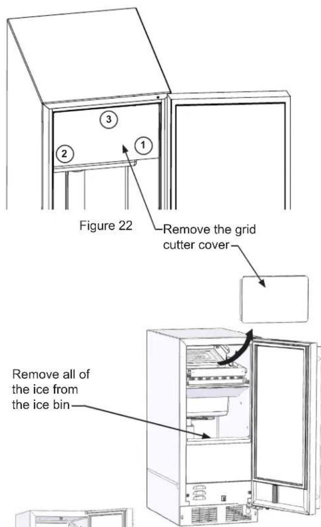
Figure 23
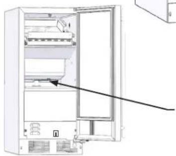
natural_image
Diagram of an open refrigerator with a black arrow pointing to the door panel (no text or symbols present)Figure 24
Remove the black reservoir drain plug from the bottom of the reservoir.
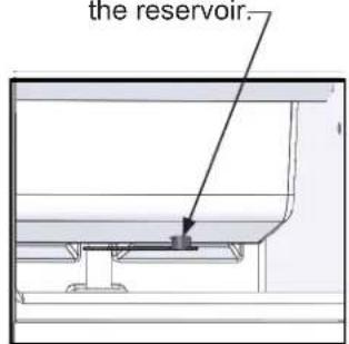
Figure 24b
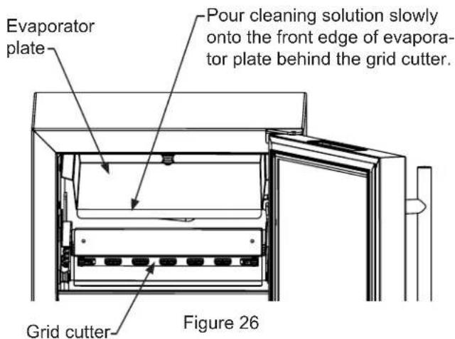
Refer to your cleaning solution instructions to determine the proper amount of cleaning solution to add based on 2 quarts (1.9 liters) of water. Remove the plastic splash shield to improve access. (See Figure 25). Pour the cleaning solution slowly on the evaporator plate so it flows down into the fresh water reservoir. (See Figure 26).
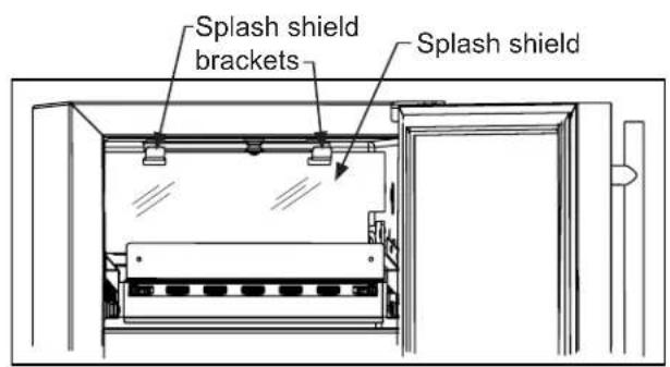
Figure 25
Replace the splash shield if removed.
Turn the ice machine back on by pressing and holding the "ON/OFF" icon for 3 seconds. The display will indicate "ICE" mode. Press and hold the "MENU" icon until a flashing "CLEAN" is displayed. Press the "ON/OFF" icon until "CLEAN" stops flashing. Your ice machine will now enter the clean cycle.

ICE

CLEAN
The clean and rinse cycle will take about 49 minutes.
After the clean cycle is complete the ice machine will return to the "OFF" position.
OFF
After the cleaning cycle is completed, verify that all build-up has been removed. If not repeat the clean cycle procedure.
NOTE
Canceling clean mode:
To exit clean mode press and hold the "ON/OFF" icon until "OFF" is displayed. Wait 3 minutes for clean mode to complete it's cancel routine before turning unit back on by pressing and holding the "ON/OFF" icon. If you turn the unit back on before the 3 minutes has elapsed, the display will show "CLEAN" and the unit will shut itself off upon completion of the 3 minute clean cancel routine.

WARNING
If you cancel clean mode after adding ice maker cleaner, you must re-start cleaning and allow clean cycle to complete to remove the cleaning solution before resuming ice production.
Optional: After the cleaning cycle has been completed, you may wash the interior with a mild detergent / dish soap or a solution of two tablespoons of baking soda and one quart of water. Rinse with clean water.
Replace the grid cutter cover.

CAUTION
Do not use bleach based cleaners or any abrasive cleaning products. Chlorine based cleaners will attack the stainless steel, making it susceptible to corrosion.
Your ice machine is now ready to restart. Press and hold the "ON/OFF" icon for 3 seconds until "ICE is displayed.

ICE
NOTE
After cleaning it is recommended you discard the ice produced after 3 hours of ice production.

CAUTION
Step 1: Verify door alignment
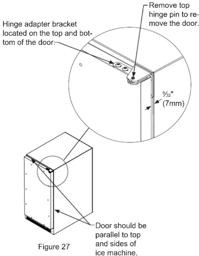
Verify that the door is aligned correctly with the cabinet prior to fabricating the custom panel. Failure to do so may result in mis-alignment of the custom panel with the hinge bracket. The door should be parallel to the sides and top of the ice machine. If alignment is necessary the door may be adjusted by loosening the 2 screws which secure the top and/or bottom hinge adapter brackets, located on the top and bottom of the door and adjusting the door side to side. Use a 532 " allen wrench, for this procedure. (See Figure 27 below). When finished aligning the door, tighten the screws securely.
NOTE
For the door to work properly it is necessary to maintain a minimum space of 932 " (7mm) between the door and cabinet flange as shown. This space can be adjusted by adjusting the top and bottom hinge adapters.
Step 2: Remove door
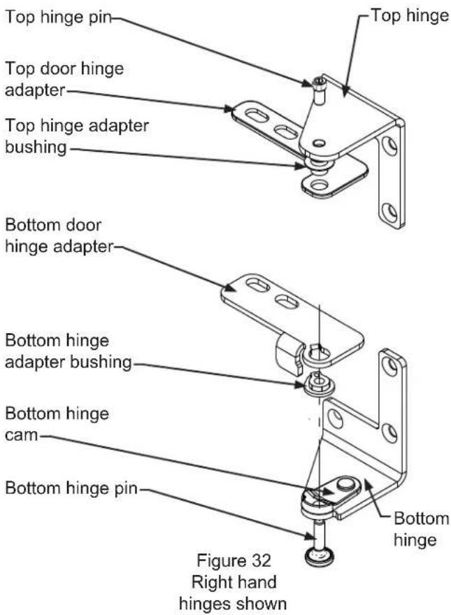
Remove the top hinge pin from the hinge with an 1/8" allen wrench. Remove the door by angling the top of the door outward and lifting the door off the bottom hinge. (See detail in Figure 27).
Step 3: Remove gasket
Lay the door on its front being careful not to scratch it. To gain access to the screw mounting holes remove the door gasket by peeling up and out of the channel.
Step 4: Cut overlay panel
Depending on the ice machine model cut the overlay panel to the dimensions shown in Figure 28 for a right hand hinged door or Figure 29 for a left hand hinged door. The 2 slots at the top and bottom are required for clearance of the hinge pins and can be made with a router and 3/8" (9.5 mm) diameter router bit.

CAUTION
Weight of the overlay panel should not exceed 20 pounds (9.1 kilograms).
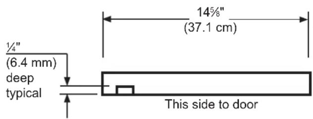
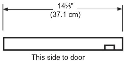
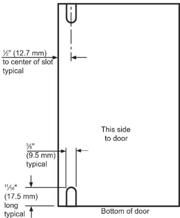
Figure 28 Panel dimensions for a right hand hinged door
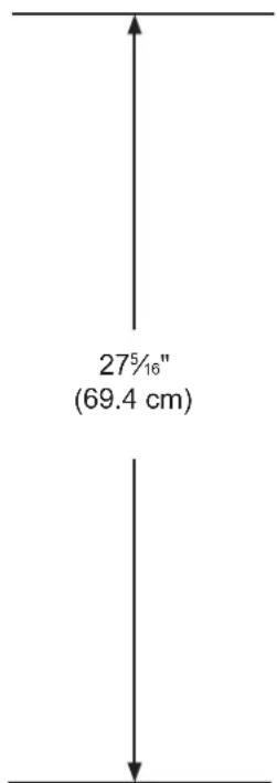
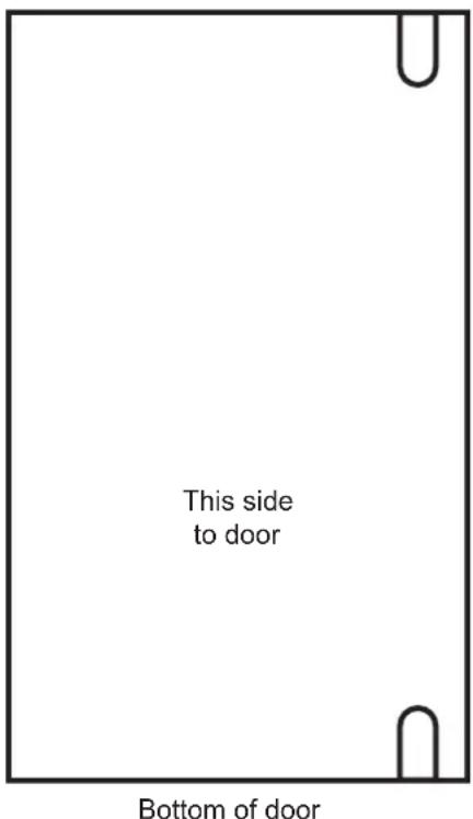
Figure 29 Panel dimensions for a left hand hinged door
Step 5: Drill necessary handle holes and mount handle:
This is a convenient time to locate and drill the holes for your handle. Most often the handle is to match that of the surrounding cabinetry. If your handle attaches from the back-side of the custom panel, locate the mounting holes while the panel is attached to the door and cabinet. After the panel is removed from the door, drill the mounting holes from the front, to the recommended diameter of the handle manufacturer. Counter bore the back-side of the panel so the screw heads do not interfere with the surface of the door.
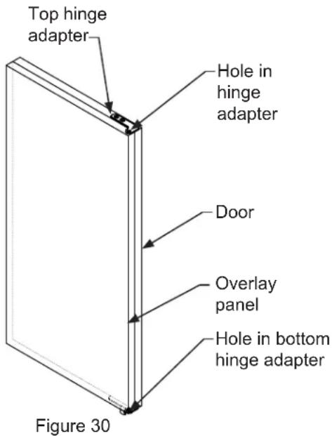
Step 6: Drill panel mounting holes
Re-clamp the panel to the door per step 5 and drill the screw pilot holes for attaching the overlay panel to the door. Select the size of the hole from Table A. Be careful not to drill the pilot holes through the overlay panel, 12 " (12.7 mm) deep for 34 " (19 mm) and 58 " (15.7 mm) panels.
Step 7: Secure overlay panel to the door.
With the #10 wood screws provided, fasten the overlay panel to the door. (See Figure 31).
| Material Type #10 Wood Screw | |
| Hardwood | 18'' (3.2 mm) Diameter Pilot Hole |
| Softwood | 764 (2.8 mm) Diameter Pilot Hole |
Table A
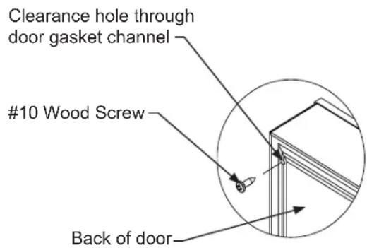
Figure 31
Press the door gasket into the door channel. Make certain the gasket corners are fully inserted. If applicable insert the key into the lock and make certain the lock operates properly.
Step 9: Install the door
Install the top and bottom hinge adapter bushings back into the hinge adapters that were removed in step 6. Install the door by reversing the procedure from step 2. Install the top hinge pin so the screw head is flush with the top surface of the hinge. A hinge parts reference diagram is shown in Figure 32.
Front Grille
Be sure that nothing obstructs the required air flow openings in front of the cabinet. At least once or twice a year, brush or vacuum lint and dirt from the front grille area (see page 4).

CAUTION
SHOCK HAZARD: Disconnect electrical power from the appliance before cleaning with soap and water.
Cabinet
The painted cabinet can be washed with either a mild soap and water and thoroughly rinsed with clear water. NEVER use abrasive scouring cleaners.
Interior
Wash interior compartment with mild soap and water. Do NOT use an abrasive cleaner, solvent, polish cleaner, undiluted detergent or chlorine based cleaners.
Care of Appliance
- Avoid leaning on the door, you may bend the door hinges or tip the appliance.
- Exercise caution when sweeping, vacuuming or mopping near the front of the appliance. Damage to the grille can occur.
- Periodically clean the interior of the appliance as needed.
- Periodically check and/or clean the front grille as needed.
In the Event of a Power Failure
If a power failure occurs, try to correct it as soon as possible. Minimize the number of door openings while the power is off so as not to adversely affect the appliance's temperature.
Light assembly replacement
All models use LED lamps to illuminate the interior of the appliance. This component is very reliable, but should one fail, contact a qualified service technician for replacement of the LED.
Energy Saving Tips
The following suggestions will minimize the cost of operating your ice machine appliance.
- Do not install your appliance next to a hot appliance, (stove, dishwasher, etc.). heating air duct, or other heat sources.
- Install product out of direct sunlight.
- Assure the front grille vents at front of the ice machine beneath the door are not obstructed and kept clean to allow ventilation for the refrigeration system to expel heat.
- Plug your appliance into a dedicated power circuit. (Not shared with other appliances).
- Minimize door openings and duration of door openings.
- Set the control to the "off" position if accessing the interior to spot clean or remove large quantities of ice requires the door to be open for an extended period of time.
- Use ECO mode if maximum ice production quantities are not required.
- Use the delay start function if the ice machine will not be used for long periods of time.
If Service is Required:
- If the product is within the first year warranty period please contact your dealer or call AGA MARVEL Customer Service at 800.223.3900 for directions on how to obtain warranty coverage in your area.
- If the product is outside the first year warranty period, AGA MARVEL Customer Service can provide recommendations of service centers in your area. A listing of authorized service centers is also available at www.agamarvel.com under the service and support section.
- In all correspondence regarding service, be sure to give the service number, serial number, and proof of purchase.
- Try to have information or description of nature of the problem, how long the appliance has been running, the room temperature, and any additional information that may be helpful in quickly solving the problem.
- Table "B" is provided for recording pertinent information regarding your product for future reference.
| For Your Records | |
| Date of Purchase | |
| Dealer's name | |
| Dealer's Address | |
| Dealer's City | |
| Dealer's State | |
| Dealer's Zip Code | |
| Appliance Serial Number | |
| Appliance Service Number | |
| Date Warranty Card Sent (Must be within 10 days of purchase). | |
Table B
Before You Call for Service
If the appliance appears to be malfunctioning, read through this manual first. If the problem persists, check the troubleshooting guide below. Locate the problem in the guide and refer to the cause and its remedy before calling for service. The problem may be something very simple that can be solved without a service call. However, it may be required to contact your dealer or a qualified service technician.
Troubleshooting guide:
Ice Machine Operation
Ice machine does not operate
Is the ice machine's power cord plugged in? Plug the power cord into a grounded 3 prong outlet.
Is the electronic control showing the "ICE" position?
Check the control to be sure it is in the "ICE" position.
Is a fuse blown or a circuit breaker been tripped? Replace a blown fuse or reset a tripped circuit breaker.
Is the temperature of the room cooler than it normally is? The minimum room temperature is 55^ F ( 13^ C). The bin thermistor may be sensing the room temperature and shut off before the bin is full of ice. If the room temperature remains low the ice machine may not restart.
Is there a drain pump in the ice machine? The drain pump is designed to temporarily shut the unit off when large quantities of water create a high-limit condition. Wait a few minutes as the drain pump will continue to operate to dispose of the excess water. If there is still water in the ice bin check the drain pump vent line and drain line for obstructions or kinking.
The ice machine is noisy
Many sounds of an ice machine are different than your household refrigerator. This subject is discussed on page 10, but check the following:
Do you hear water being circulated in the ice machine? This is a normal sound as water is added once every ice making cycle.
Is there a "whoosing" sound? Make sure water is getting to the ice machine. Also check to make sure the drain plug is fully seated in the water reservoir.
Is there an ice slab caught between the evaporator plate and the grid cutter? First check to see if the ice machine is level. If the ice machine is level run a cleaning cycle.

WARNING
Electrocution Hazard
- Never attempt to repair or perform maintenance on the appliance until the main electrical power has been disconnected. Turning the appliance control "OFF" does not remove electrical power from the unit's wiring.
- Replace all parts and panels before operating.
Ice Production
Little or no ice production from the ice machine Is the electronic control set to the "ICE" position?
Check the control to be sure it is in the "ICE" position.
Is water getting to the ice machine? Make sure nothing is restricting the water supply such as a closed water valve or a blown fuse or tripped circuit breaker, or a kinked supply line, or low water pressure.
Has the ice machine just been started? A typical ice production cycle can take up to 112 hours. Initial start up cycles can take longer. Check the ice machine after 24 hours for ice accumulation in the bin.
Is the reservoir drain plug in place? Check that the reservoir drain plug is properly seated.
Is the water distributor tube restricted? Run a cleaning cycle to clean the ice machine. Also check any filters to make sure they are not restricted.
Is the condenser fan air flow restricted? Make sure the grille in the front of the ice machine is open for proper air circulation.
Is the room and/or water temperature to warm? Move the ice machine to an area where the ambient temperature is below 90^ F ( 32^ C) or below 100^ F ( 38^ C) for freestanding ice machines. The ice machine should not be placed next to a heat source such as an oven. Check the cold water connection.
Is there scale build up in the ice machine? If there is scale build up on the evaporator, the ice machine needs to be cleaned. See "Cleaning the Ice machine".
Ice Quality
Odor, grey color, or off taste in the ice
Is there mineral scale build up on the evaporator plate? The ice machine needs cleaning. See "Cleaning the Ice Machine".
Is there a high mineral content in the water? The water may need to be filtered.
Are food items being stored in the ice bin? Remove food from the ice bin.
Unpleasant Odors may require the use of a charcoal filter on the water supply line.
Clumps of ice
Are there clumps of ice in the bin? If the ice isn't used on a regular basis it will melt and form into clumps. Break up the ice clumps with the ice scoop.
Ice cubes are too big or too small
Is there low ice consumption? Ice is slowly melting in the ice bin which will affect the size of the cubes. This is normal. When the ice bin needs to be replenished, cubes will return to the regular size.
Is the ice slab releasing? Clean the evaporator. See "Cleaning the Ice Machine".
Is the distributor tube restricted? Check the water line to the ice machine to make sure there are no restrictions or kinks in the line. Check all filters to make sure they are not restricted. Check that the water flows evenly out of the distributor tube, if not, clean the ice machine. See "Cleaning the Ice Machine".
Plumbing Problems
Is the drain hose aligned over the drain? Move the ice machine to align the drain.
Is the ice machine draining properly? Check that there are no kinks or restrictions in the drain lines; this can cause water to back up in the ice bin. Check that foreign material is not blocking the ice bin drain located at the right rear corner of the ice bin. Check the drain pump discharge and vent line or any restrictions or kinks. Check that the drain pump is level.
NOTE
If there are plumbing issues outside of the ice machine, they cannot be repaired by the service technician. A qualified plumber will have to be called.
Troubleshooting the Drain Pump
NOTE
If the drain pump reservoir (not the ice machine bin) reaches overfill condition, the power to the ice machine will be shut off.
If the ice machine is not working, check the following:
- Make sure there is power at the receptacle.
- Make sure the ice machine is turned on.
• Make sure the ice bin is not full.
Then check the drain pump:
The pump does not run:
- Make sure the pump is plugged in and there is power to the receptacle.
- Check the inlet to the drain pump for debris and clean as needed. Remove clamps and inlet tube from drain pump to check for and remove debris.
- Make certain the vent line is free of kinks/sharp bends or restrictions.
- Make certain there is enough water to activate the drain pump. It will take at least one (1) quart (.95 liters) of water to activate the drain pump.
The pump runs, but no water is pumped out:
- Check that the vent is clear and free of restrictions.
- Check the discharge line to make certain there are no restrictions.
- Make sure that the discharge tubing has not exceeded the maximum lift of eight (8) feet (2.44 meters) and the horizontal run is not greater than twenty (20) feet (6.1 meters).
The pump runs and then quickly turns off repeatedly:
- Check to make certain the drain pump is level.
- Check that the vent is clear and free of restrictions.
The ice machine is running but not producing ice:
- Check to make sure water is not backing up in the ice bin.
If the ice machine is moved, not used for an extended period of time, or will be in an area that will be near freezing temperatures, it is necessary to remove any remaining water in the ice-making system.

CAUTION
This ice machine must have all water drained and removed to prevent ice machine damage as well as possible water damage to the surrounding area in freezing conditions. These damages are not covered under warranty.

CAUTION
Do not use any type of anti-freeze or other solution as a substitution for properly draining the ice machine.
Clean the Ice Machine
Cleaning the ice machine will help prevent mold and mildew growth as well as sanitize the ice machine for storage or when it is put back into service. See page 16 for instructions for cleaning the ice machine.

WARNING
Electrocution Hazard
Risk of electrical shock or personal injury could occur due to moving components, if machine compartment access cover is removed before unplugging the ice machine.
Draining and Removing Water from the Ice-Making System with a Gravity Drain.
- Turn off the water supply to the ice machine.
- Disconnect the water supply fitting at the inlet of the water valve. (See Figure 33a).
- Change the electronic control to the "CLEAN" position for approximately one (1) minute. This will energize and open the water valve and remove most of the water from the water valve and the water valve's outlet water line to the reservoir.
- Change the electronic control to the "OFF" position. This will energize and open the drain valve to drain the reservoir and the ice machine drain system.
- Unplug the ice machine from the electrical outlet.
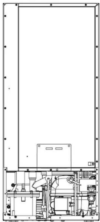
- Remove the access cover from the rear of the ice machine. (See Figure 34).
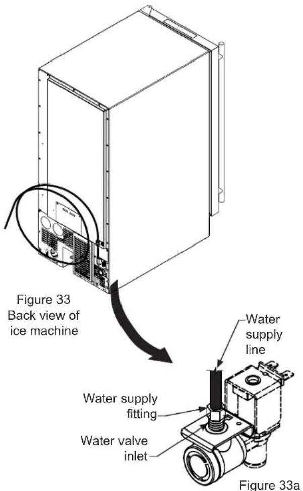
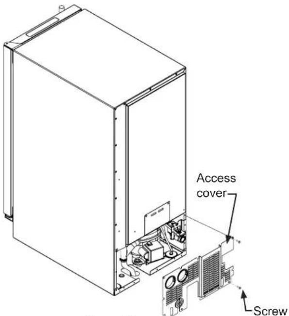
Figure 34
- Disconnect the water valve's outlet water line to the reservoir and drain the remaining water left in the water line trap area. (See Figure 35 and 35a).
natural_image
Technical line drawing of an internal machine or enclosure with no visible text, numbers, or symbols.Figure 35
To disconnect the water outlet line: Push up on the white collar and pull the plastic water line from the bottom of the water valve.
To reconnect the water outlet line: Simply insert the plastic tubing into the white collar and push until it stops (about 12 ", 12 mm, of water line will enter the valve).
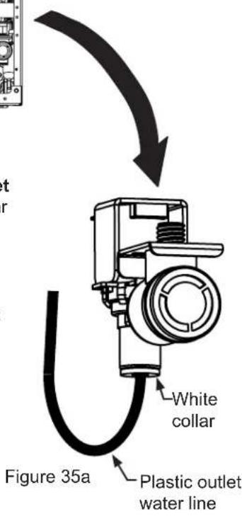
- Reconnect the water valve outlet water line. (See Figure 35 and 35a).
- Reinstall the ice machine's access cover.
- Clean and dry the ice machine's storage bin.
- Prop the door open for air circulation to prevent mold and mildew.
- Leave the water supply line disconnected or reconnect the supply line and leave it shut off. Do NOT turn the water on and allow water to enter back into the water valve.
Draining Water for Factory Installed Drain Pump Applications
Follow steps 1 through 12 for the gravity drain then do the following:
- Install the winterization plug in the water drain hole inside the ice bin. (See Figure 36).
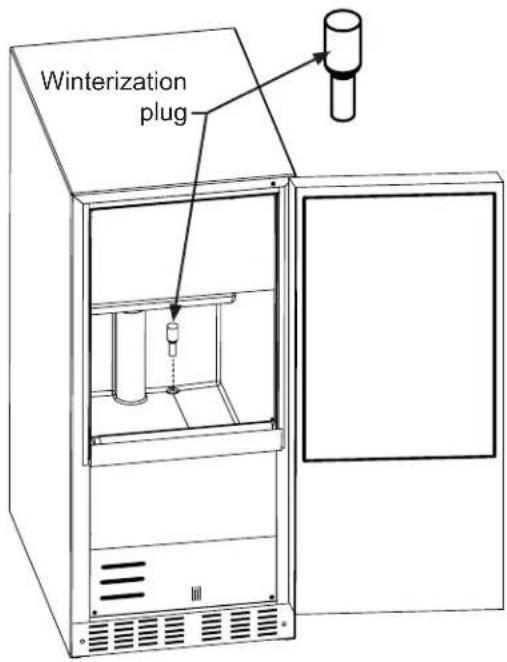
Figure 36
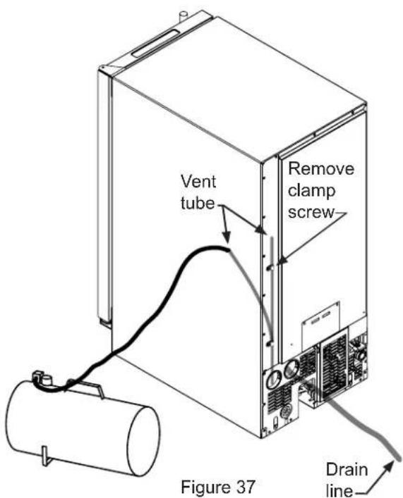
- Remove the top clamp from the vent tube, for easier access for the air hose.
- Apply air pressure (approximately 10 psi) to the end of the vent tube which will purge the remainder of the water from the drain pump and the drain line. (See Figure 37).
- Reinstall the vent tube and clamp to the back of the ice machine and remove the winterization plug from the ice bin and save it for future use.
To Restart the Ice Machine
- Reconnect or turn on the water supply line.
- Reconnect drain tubing if removed.
- Plug in the power cord to a wall outlet and turn the ice machine on, (refer to page 14 for turning the ice machine on and off).
- Check the water inlet, drain lines, and fittings for any water leaks.
- Check drain pump (if equipped) operation by pouring approximately two (2) quarts of water into the ice storage bin. The drain pump should activate and discharge water (refer to Drain Pump on page 7). Check for water leaks at all hose connections.
Drain Pump Removal Instructions:
- Unplug the ice machine from the electrical supply and remove the rear access cover from the ice machine. (See page 27 for instructions).
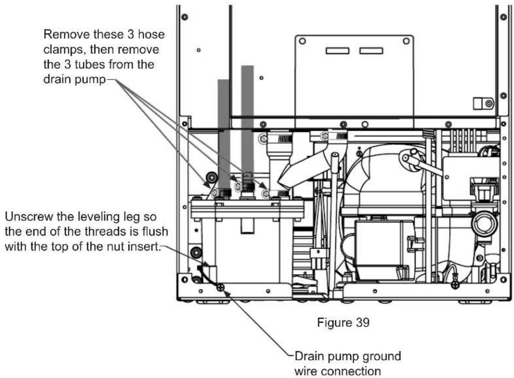
- Unscrew the leveling leg in the back corner until the end of the threaded portion is flush with the threaded nut insert in the base. (see Figure 39).
- Unscrew the 3 hose clamps and remove the 3 hoses from the front of the drain pump. (See Figure 39).
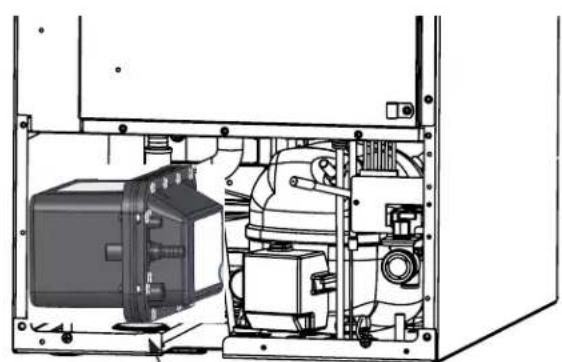
- Rotate the drain pump and remove from the ice machine, (See Figure 38). It may be necessary to disconnect the ground wire connection in the back flange of the cabinet. (See Figure 39).
- Disconnect the ice machine power cord from the drain pump (See Figure 40).
- Drain the water in the drain pump's reservoir by turning the pump upside down and allowing water to drain through the pump's inlet and vent tube fittings.
- Installation of drain pump is reverse of this procedure.
natural_image
Technical line drawing of an internal mechanical or electrical enclosure with no visible text or symbolsFigure 38
Rotate drain pump and remove from back of ice machine.
Additional issues to be inspected by the installer upon service replacement:
- The drain pump must be level.
- No pinched water lines.
- No interference with electrical cords or wiring.
- The drain pump should not set on any obstacles, wiring, etc.
- Secure all hose clamps leading to and from the drain pump.
- Insure that the vent tube height is adequate - 18 inches minimum.
- Insure that drain height is adequate - maximum of 8 feet.
- Insure that drain length is adequate - maximum of 20 feet.
- Checked for water leaks after installation of the drain pump.
- Check for vibrations caused by improper installation.
- Insure that there is no interference with back access cover.
- Insure that the hole grommets are in place at each location so that any vent or drain tubes do not rub on any sharp surfaces.
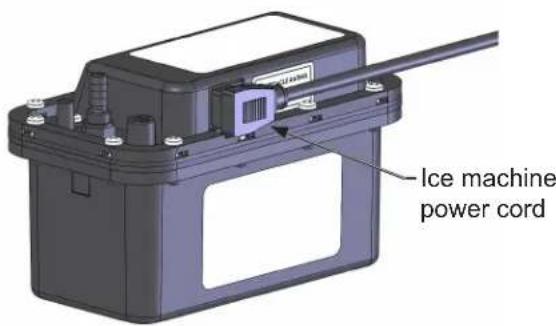
Figure 40
Entire Product
Limited One Year Parts and Labor Warranty
AGA MARVEL warrants that it will supply all necessary parts and labor to repair or replace in the end user's home or office, any component which proves to be defective in material or workmanship, subject to the condition and exclusions stated below, for a period of one year from the date of purchase by the end user.
Additional Second Through Fifth Year Limited Parts Only Warranty
During the four years following expiration of the one year limited warranty, AGA MARVEL will supply replacement parts for the hermetically sealed refrigeration system which consists of the compressor, condenser, drier, accumulator, bypass valve, connecting tubing and the evaporator that are proven to be defective due to workmanship or materials subject to the conditions and exclusions below.
The above warranties do not cover:
- Shipping costs of replacement parts or returned defective parts.
- Customer education or instructions on how to use the appliance.
- Any content loss due to product failure.
- Removal or installation of product.
Nor do the above warranties cover failure of this product or its components due to:
- Transportation or subsequent damages.
- Commercial use or use other than normal household or small office.
- Improper installation, misuse, abuse, accident or alteration, use of wiring not conforming to electrical codes, low or high voltages, failure to provide necessary maintenance, or other unreasonable use.
Parts or Service
Not Supplied or Designated by AGA MARVEL
The above warranties also do not apply if:
- The original bill of sale, deliver date, or serial number cannot be verified.
- Defective parts are not returned for inspection if so requested by AGA MARVEL.
- The refrigeration equipment is not in the possession of the original end use purchaser.
The warranties set forth herein are the only warranties extended by AGA MARVEL. Any implied warranties, including the implied warranty of merchantability, are limited to the duration of these express warranties. In no event shall AGA MARVEL be liable for any consequential or incidental damages or expenses resulting from breach of these or any other warranties, whether express or implied.
Some states do not allow the exclusion or limitation of consequential damages or a limitation on how long an implied warranty lasts, so the above exclusion or limitation may not apply to you. This warranty gives you specific legal rights and you may have other rights that may vary from state to state.
No person, firm, or corporation is authorized to make any other warranty or assume any other obligation for AGA MARVEL. These warranties apply only to products used in any of the fifty states of the United States and the District of Columbia.
To obtain performance of this warranty, report any defects to:
AGA MARVEL
1260 E. VanDeinse St.
Greenville MI 48838
Phone: 800.223.3900

www.agamarvel.com
AGA MARVEL
1260 E. VanDeinse St.
Greenville MI 48838
800.223.3900
41014170-EN Rev A
8/29/16
All specifications and product designs subject to change without notice. Such revisions do not entitle the buyer to corresponding changes, improvements, additions, replacements or compensation for previously purchased products.
EN Installation, Operation and Maintenance Instructions
• Assistance technique : techsupport@agamarvel.com
natural_image
Technical line drawing of a mechanical component with two pins and a shaft (no text or symbols)Figure 3
natural_image
Prohibition sign showing a crossed-out electrical component (no text or symbols)Figure 4

AVERTISSEMENT
natural_image
Simple line drawing of an electrical plug and two socket outlets (no text or symbols)Figure 6
REMARQUE
natural_image
Technical line drawing of a mechanical component with grooves and mounting holes (no text or symbols)Figure 12
natural_image
Technical line drawing of a mechanical device with internal components and no visible text or symbolsFigure 14
natural_image
Technical line drawing of a mechanical component with multiple slots and scattered cubic components (no text or symbols)Figure 15
DIMENSIONS DU PRODUIT
| DONNÉES DE PRODUIT | ||
| MODÈLE | BESOINS ÉLECTRIQUES # | POIDS DU PRODUIT |
| MA15C*S | 15V/60Hz/15A | 100 lbs (45,5 kg) |
| MA15C*P | 15V/60Hz/15A | 100 lbs (45,5 kg) |
natural_image
Interior view of a refrigerator showing the door, front panel, and side panel (no text or symbols visible)Figure 24
natural_image
Technical line drawing of an internal mechanical or electrical enclosure with no visible text or symbolsFigure 35
natural_image
Technical line drawing of an internal mechanical or electrical enclosure with no visible text or symbolsAll specifications and product designs subject to change without notice. Such revisions do not entitle the buyer to corresponding changes, improvements, additions, replacements or compensation for previously purchased products.
EN Installation, Operation and Maintenance Instructions
Modo Delayed Start....15
natural_image
Technical line drawing of a mechanical component with two pins and a base (no text or symbols)Figura 3
Figura 4

ADVERTENCIA
natural_image
Simple line drawing of an electrical plug and two separate electrical outlets (no text or symbols)Figura 6
NOTA
natural_image
Technical line drawing of a mechanical component with grooves and mounting holes (no text or symbols)Figura 12
natural_image
Technical line drawing of a mechanical device with internal components and no visible text or symbolsFigura 14
natural_image
Technical line drawing of a mechanical component with multiple slots and scattered cubic components (no text or symbols)Figura 15
DIMENSIONES DEL PRODUCTO
| DIMENSIONES DE LA ABERTURA DE INSTALACIÓN pulgadas (cm) DIMENSIONES DEL GABINETE pulgadas (cm) | |||||||||
| MODELO | "A" | "B" | "C" | "D" | "E" | "F" | "G" | "H" | "J" |
| MA15C*S | 15"(38,1 cm) | ** 3138 " to 3238 " (79,7 to 82,2 cm) | 24"(61 cm) | 1412 " (37,8 cm) | 3118 " to 3218 " (79,1 to 81,6 cm) | 2358 " (60 cm) | 2512 " (64,8 cm) | 37116 " (95,4 cm) | 16316 " (42,1 cm) |
| MA15C*P | 15"(38,1 cm) | ** 3138 " to 3238 " (79,7 to 82,2 cm) | * 24"(61 cm) | 1412 " (37,8 cm) | 3118 " to 3218 " (79,1 to 81,6 cm) | 2218 " (58,1 cm) | - | 37116 " (95,4 cm) | 1318 " (35,3 cm) |

ESTILO DE LA PUERTA
(S) Puerta maciza
(P) Puerta maciza decorativa (sin manija)
DIMENSIONES DEL PRODUCTO
| DATOS DEL PRODUCTO | ||
| MODELO | REQUISITOS ELÉCTRICOS # | PESO DEL PRODUCTO |
| MA15C*S | 15V/60Hz/15A | 100 lbs (45,5 kg) |
| MA15C*P | 15V/60Hz/15A | 100 lbs (45,5 kg) |
natural_image
Diagram of an open refrigerator with a black arrow pointing to the door (no text or symbols visible)Figura 24
natural_image
Technical line drawing of an internal mechanical or electrical enclosure with no visible text or symbolsFigura 35
natural_image
Technical line drawing of an internal mechanical or electrical enclosure with no visible text or symbols- Welcome
- Warranty Registration:
- To Register:
- About your Marvel clear ice machine:
- Performance
- Storage Capabilities
- Touchscreen Controls
- Aesthetics
- Important Safety Instructions
- Recognize Safety Symbols, Words, and Labels.
- WARNING
- CAUTION
- NOTE
- EXCESSIVE WEIGHT HAZARD
- Remove Interior Packaging
- Important
- Note to Customer
- WARNING - Help Prevent Tragedies
- Select Location
- Cabinet Clearance
- Front Grille
- Leveling Legs
- Electrical Shock Hazard
- Electrical Connection
- Drain Plumbing
- Gravity Drain (no drain pump):
- With a factory installed drain pump:
- Optional Drain Pump.
- Water Supply
- The Ice Making Process
- Ice Production
- New Sounds
- Display icons:
- Display area text:
- ICE
- ECO
- OFF
- DOOR
- CLEAN
- Delay start/Vacation mode:
- Starting your clear ice machine:
- Turning your ice machine On and Off:
- Control Lock:
- Door ajar alarm:
- Error codes:
- Clean reminder:
- Options menu:
- Normal and ECO mode:
- Clean mode:
- Once you have your cleaner:
- Canceling clean mode:
- Step 1: Verify door alignment
- Step 2: Remove door
- Step 3: Remove gasket
- Step 4: Cut overlay panel
- Step 5: Drill necessary handle holes and mount handle:
- Step 6: Drill panel mounting holes
- Step 7: Secure overlay panel to the door.
- Step 9: Install the door
- Cabinet
- Interior
- Care of Appliance
- In the Event of a Power Failure
- Light assembly replacement
- Energy Saving Tips
- The following suggestions will minimize the cost of operating your ice machine appliance.
- If Service is Required:
- Before You Call for Service
- Troubleshooting guide:
- Ice Machine Operation
- Ice machine does not operate
- The ice machine is noisy
- Electrocution Hazard
- Little or no ice production from the ice machine Is the electronic control set to the "ICE" position?
- Ice Quality
- Odor, grey color, or off taste in the ice
- Clumps of ice
- Ice cubes are too big or too small
- Plumbing Problems
- Troubleshooting the Drain Pump
- If the ice machine is not working, check the following:
- Then check the drain pump:
- The pump does not run:
- The pump runs, but no water is pumped out:
- The pump runs and then quickly turns off repeatedly:
- The ice machine is running but not producing ice:
- Clean the Ice Machine
- Draining and Removing Water from the Ice-Making System with a Gravity Drain.
- Draining Water for Factory Installed Drain Pump Applications
- To Restart the Ice Machine
- Drain Pump Removal Instructions:
- Additional issues to be inspected by the installer upon service replacement:
- Entire Product
- Limited One Year Parts and Labor Warranty
- Additional Second Through Fifth Year Limited Parts Only Warranty
- Parts or Service
- Not Supplied or Designated by AGA MARVEL
- AGA MARVEL
- AVERTISSEMENT
- REMARQUE
- DIMENSIONS DU PRODUIT
- ADVERTENCIA
- NOTA
- DIMENSIONES DEL PRODUCTO
- ESTILO DE LA PUERTA
Brand : Marvel
Model : MA15CPP2LP
Category : Sorbet maker