
DP55360 - Television SANYO - Free user manual and instructions
Find the device manual for free DP55360 SANYO in PDF.


| Product Type | HDTV |
| Brand | Sanyo |
| Model | DP55360 |
| Screen Size | 55 inches (diagonal) |
| Display Technology | LCD with LED backlight |
| Maximum Resolution | 1920 x 1080 (Full HD 1080p) |
| Refresh Rate | 120 Hz (Motion Sync) |
| Power Requirement | AC 120V, 60Hz |
| Power Consumption | 195 watts |
| Weight | 75 lbs (34 kg) |
| Dimensions (with stand) | 51.2 x 34.5 x 10.9 inches (W x H x D) |
| Dimensions (without stand) | 51.2 x 32.3 x 2.4 inches (W x H x D) |
| VESA Mount Pattern | 400 x 400 mm (M6 screws, max length 12mm) |
| HDMI Inputs | 3 (HDMI 1-3) |
| Component Video Inputs | 2 (VIDEO2 and VIDEO3) |
| Composite Video Inputs | 1 (VIDEO1) |
| S-Video Input | 1 (VIDEO1) |
| PC Input | 1 (D-Sub 15-pin RGB) |
| USB Port | 1 (for photo viewer, JPEG only) |
| Ethernet Port | 1 (for internet connectivity) |
| Digital Audio Output | 1 (Coaxial) |
| Analog Audio Output | 1 set (L/R stereo RCA) |
| Energy Star Certified | Yes |
| V-Chip Parental Controls | Yes (standard and advanced RRT5) |
| Warranty | 1 year limited parts and labor |
Frequently Asked Questions - DP55360 SANYO
User questions about DP55360 SANYO
0 question about this device. Answer the ones you know or ask your own.
Ask a new question about this device
Download the instructions for your Television in PDF format for free! Find your manual DP55360 - SANYO and take your electronic device back in hand. On this page are published all the documents necessary for the use of your device. DP55360 by SANYO.
USER MANUAL DP55360 SANYO
natural_image
Computer monitor displaying a grayscale image of Earth from space, showing continents and cloud cover (no text or symbols visible)DP55360
Model No. / No. de Modelo
CAUTION
RISK OF ELECTRIC SHOCK DO NOT OPEN!
CAUTION: TO REDUCE THE RISK OF ELECTRIC SHOCK, DO NOT REMOVE COVER (OR BACK). NO USER-SERVICEABLE PARTS INSIDE. REFER SERVICING TO QUALIFIED SERVICE PERSONNEL.
THIS SYMBOL INDICATES THAT DANGEROUS VOLTAGE CONSTITUTING A RISK OF ELECTRIC SHOCK IS PRESENT WITHIN THIS UNIT.

THIS SYMBOL INDICATES THAT THERE ARE IMPORTANT OPERATING AND MAINTENANCE INSTRUCTIONS IN THE LITERATURE ACCOMPANYING THIS UNIT.

WARNING: TO REDUCE THE RISK OF FIRE OR ELECTRIC SHOCK, DO NOT EXPOSE THIS APPLIANCE TO RAIN OR MOISTURE.
IMPORTANT SAFETY INSTRUCTIONS
- Read these instructions.
- Keep these instructions.
- Heed all warnings.
- Follow all instructions.
- Do not use this apparatus near water.
-
Clean only with dry cloth.
-
Do not block any ventilation openings. Install in accordance with the manufacturer's instructions.
-
Do not install near any heat sources such as radiators, heat registers, stoves, or other apparatus (including amplifiers) that produce heat.
-
Do not defeat the safety purpose of the polarized or grounding-type plug. A polarized plug has two blades with one wider than the other. A grounding-type plug has two blades and a third grounding prong. The wide blade or the third prong are provided for your safety. If the provided plug does not fit fully into your outlet, consult an electrician for replacement of the obsolete outlet.
-
Protect the power cord from being walked on or pinched particularly at plugs, convenience receptacles, and the point where they exit from the apparatus.
-
Only use attachments/accessories specified by the manufacturer.
-
Use only with the cart, stand, tripod, bracket, or table specified by the manufacturer, or sold with the apparatus. When a cart is used, use caution when moving the cart/apparatus combination to avoid injury from tip-over.
-
Unplug this apparatus during lightning storms or when unused for long periods of time.
-
Refer all servicing to qualified service personnel. Servicing is required when the apparatus has been damaged in any way, such as power-supply cord or plug is damaged, liquid has been spilled or objects have fallen into the apparatus, the apparatus has been exposed to rain or moisture, does not operate normally, or has been dropped.

- If an outside antenna is connected to the television equipment, be sure the antenna system is grounded so as to provide some protection against voltage surges and built up static charges. In the U.S. Selection 810-21 of the National Electrical Code provides information with respect to proper grounding of the mast and supporting structure, grounding of the lead-in wire to an antenna discharge unit, size of grounding conductors, location of antenna discharge unit, connection to grounding electrodes, and requirements for the grounding electrodes.
- An outside antenna system should not be located in the vicinity of overhead power lines or other electrical light or power circuits, or where it can fall into such power lines or circuits. When installing an outside antenna system, extreme care should be taken to keep from touching such power lines or circuits as contact with them might be fatal.
EXAMPLE OF ANTENNA GROUNDING ACCORDING TO NATIONAL ELECTRICAL CODE, ANSI/NFPA 70
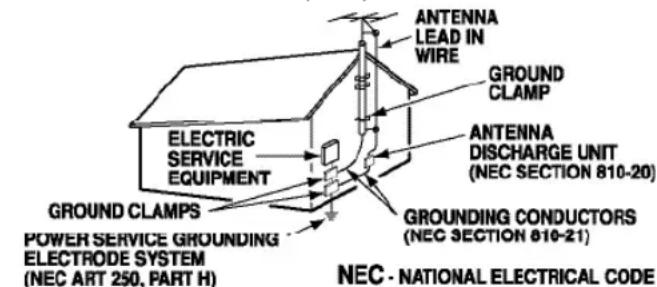
"Note to CATV system installer:
This reminder is provided to call the CATV system installer's attention to Article 820-40 of the NEC that provides guidelines for proper grounding and, in particular, specifies that the cable ground shall be connected to the grounding system of the building, as close to the point of cable entry as practical."
- Wall or Ceiling Mounting—The product should be mounted to a wall or ceiling only as recommended by the manufacturer.
- Apparatus shall not be exposed to dripping or splashing and no objects filled with liquids, such as vases, shall be placed on the apparatus.
- When the MAINS plug is used as the disconnect device, the disconnect device shall remain readily operable.
FCC INFORMATION
This equipment has been tested and found to comply with the limits for a Class B digital device, pursuant to Part 15 of the FCC Rules. These limits are designed to provide reasonable protection against harmful interference in a residential installation. This equipment generates, uses and can radiate radio frequency energy and, if not installed and used in accordance with the instructions, may cause harmful interference to radio communications. However, there is no guarantee that interference will not occur in a particular installation. If this equipment does cause harmful interference to radio or television reception, which can be determined by turning the equipment off and on, the user is encouraged to try to correct the interference by one or more of the following measures:
- Reorient or relocate the receiving antenna.
- Increase the separation between the equipment and receiver.
- Connect the equipment into an outlet on a circuit different from that to which the receiver is connected.
- Consult the dealer or an experienced radio/TV technician for help.
CAUTION: FCC Regulations state that improper modifications or unauthorized changes to this unit may void the user's authority to operate the unit.
TRADEMARKS

Manufactured under license from Dolby Laboratories. Dolby and the double-D symbol are trademarks of Dolby Laboratories.

HDMI, the HDMI Logo and High-Definition Multimedia Interface are trademarks or registered trademarks of HDMI Licensing LLC in the United States and other countries.

As an Energy Star® Partner, Sanyo Manufacturing Corporation has determined that this product meets the Energy Star® guidelines for energy efficiency.

This symbol on the nameplate means the product is Listed by Underwriter's Laboratories Inc. It is designed and manufactured to meet rigid U.L. safety standards against risk of fire, casualty and electrical hazards.

Adobe®, Adobe Flash®, and Flash Lite® are either registered trademarks or trademarks of Adobe Systems Incorporated in the United States and/or other countries.
PC RESOLUTION CHART
| RETOLUTION | ASPECT RATIO | REFRESH RATE | HORIZONTAL FREQUENCY | VERTICAL FREQUENCY |
| 640 x 480 | 4:3 | 60 Hz | 31.47 kHz | 69.94 Hz |
| 72 Hz | 37.86 kHz | 72.81 Hz | ||
| 75 Hz | 37.50 kHz | 75.00 Hz | ||
| 85 Hz | 43.27 kHz | 85.01 Hz | ||
| 720 x 400 | 18:10 | 70 Hz | 31.47 kHz | 70.00 Hz |
| 800 x 600 | 4:3 | 68 Hz | 35.16 kHz | 66.25 Hz |
| 60 Hz | 37.88 kHz | 60.32 Hz | ||
| 72 Hz | 48.08 kHz | 72.19 Hz | ||
| 75 Hz | 46.88 kHz | 75.00 Hz | ||
| 85 Hz | 63.57 kHz | 85.06 Hz | ||
| 1024 x 768 | 4:3 | 60 Hz | 48.36 kHz | 60.00 Hz |
| 70 Hz | 56.48 kHz | 70.07 Hz | ||
| 75 Hz | 60.02 kHz | 75.02 Hz | ||
| 85 Hz | 68.88 kHz | 85.00 Hz | ||
| 1152 x 864 | 4:3 | 75 Hz | 67.90 kHz | 75.00 Hz |
| 1280 x 768 | 5:3 | 60 Hz | 47.40 kHz | 60.00 Hz |
| 60 Hz | 47.78 kHz | 69.87 Hz | ||
| 75 Hz | 60.29 kHz | 74.89 Hz | ||
| 85 Hz | 68.63 kHz | 84.84 Hz | ||
| 1280 x 960 | 4:3 | 60 Hz | 60.00 kHz | 60.00 Hz |
| 86 Hz | 85.94 kHz | 85.00 Hz | ||
| 1280 x 1024 | 5:4 | 60 Hz | 63.98 kHz | 60.02 Hz |
| 75 Hz | 79.98 kHz | 76.02 Hz | ||
| 85 Hz | 91.18 kHz | 86.02 Hz | ||
| 1360 x 768 | 16:9 | 60 Hz | 47.71 kHz | 60.00 Hz |
| 1440 x 500 | 16:10 | 60 Hz | 65.83 kHz | 69.89 Hz |
| 80 Hz | 55.47 kHz | 59.90 Hz | ||
| 1920 x 1080 | 16:9 | 60 Hz | 67.50 kHz | 60.00 Hz |
This Class B digital apparatus complies with Canadian ICES-003.
CONTENTS
IMPORTANT SAFETY INSTRUCTIONS ..... 2
FCC INFORMATION 3
TRADEMARKS 3
PC RESOLUTIONS 3
CONTENTS 4
SPECIFICATIONS 4
PROTECTING THE SCREEN ....4
POSITIONING THE HDTV 5
STAND REMOVAL/WALL MOUNTING ....5
GETTING STARTED—
Remote Control Battery Installation ....5
Antenna Connections for off-air or cable .....5
HDTV INPUT/OUTPUT REFERENCE....6
A/V CONNECTIONS (SIDE PANEL) 7
A/V CONNECTIONS (BACK PANEL) 8
POWER CONNECTION / INITIAL CHANNEL SEARCH . . .9
REMOTE CONTROL OPERATION....10
Channel Scan Memory ....11
Input Setting 11
Video3 Setting 12
HDMI Linking 12
Setup 13
Menu Language 13
Digital Caption 13
Energy Setting 13
Clock Timer 14
Motion Sync 14
V-Chip 15
Picture 16
Sound 17
PC CONNECTIONS & MENU OPERATION .....18
PHOTO VIEWER 19
WARRANTY....20
"The American Academy of Pediatrics discourages television viewing for children younger than two years of age"
SPECIFICATIONS
Power Requirement: Source: AC 120V, 60Hz
AC Power Consumption: Weight:
195 watts 75 lbs.
Dimensions:
MODEL WIDTH HEIGHT DEPTH
DP55360 51.2 34.5 10.9
w/o stand 32.3 2.4
NOTE: Dimensions are in inches
Please read before operating your HDTV!
PROTECTING THE SCREEN
CAUTION: The screen can be damaged if it is not maintained properly.
- Do not use hard objects such as hard cloth or paper to clean the screen.
- Do not use excessive pressure when cleaning the screen; excessive pressure can cause permanent discoloration or dark spots.
- NEVER spray liquids on the screen.

HANDLING PRECAUTIONS
- Handle by the cabinet only.
- Never touch the screen when handling.
- Handling damage is not covered under warranty.
POSITIONING THE HDTV
- Always use a firm and flat surface when positioning your HDTV.
- Do not position the unit in a confined area.
- Allow adequate space for proper ventilation.
STAND REMOVAL AND WALL MOUNTING (OPTIONAL)
Tools Needed: Phillips screwdriver

IMPORTANT NOTE: Place HDTV face down on a padded or cushioned flat surface to protect the screen and finish.
Wall mounting of the HDTV must be performed by a skilled person.
1 Remove the two (2) screws holding the stand base cover and carefully dislodge.
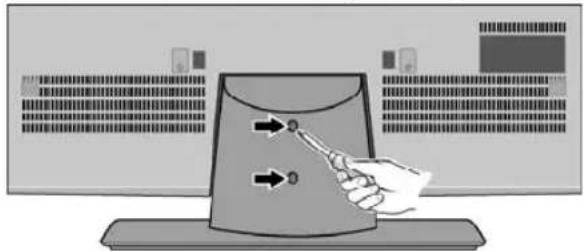
natural_image
Illustration of a hand interacting with a computer monitor displaying a button, no text or symbols present2 Remove the four (4) screws securing the stand base to the HDTV. CAUTION: Hold the stand firmly as you remove the last screw.
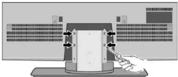
natural_image
Diagram of a hand interacting with a device panel and control panel (no text or symbols visible)3 Use the screws that are threaded into the four (4) inserts on the back of your HDTV to secure it to an appropriate wall mounting kit.
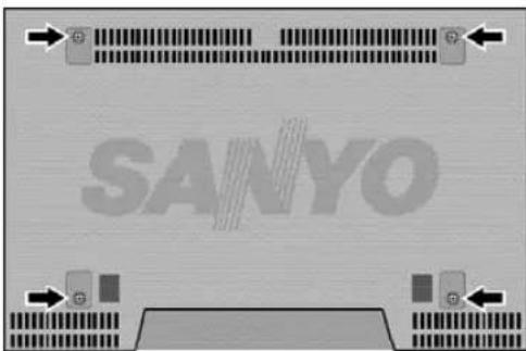
VESA standard interface: 400 x 400
Mounting screws measurements:
M6 (6mm) Diameter, Length - 12mm (maximum)
NOTE: Wall mounting kit is not included.
GETTING STARTED
1 BATTERY INSTALLATION
Install two (2) "AAA" batteries in the remote control. (Not included)

To ensure safe operation, please observe the following precautions:
- Replace both batteries at the same time. Do not use a new battery with a used battery.
- There's a risk of explosion if a battery is replaced by an incorrect type.
- Do not expose the Remote Control unit to moisture or heat.
- Be sure to match the “+” and “−” signs on the batteries with marks inside the remote control.
2 ANTENNA CONNECTION FOR OFF-AIR SIGNALS OR CABLE
Hook up your antenna or your cable service to the HDTV's ANT terminal with the use of a 75 OHM coaxial cable.
NOTE: Keep your indoor antenna at least 3 ft. away from the television set and any other electronic equipment.
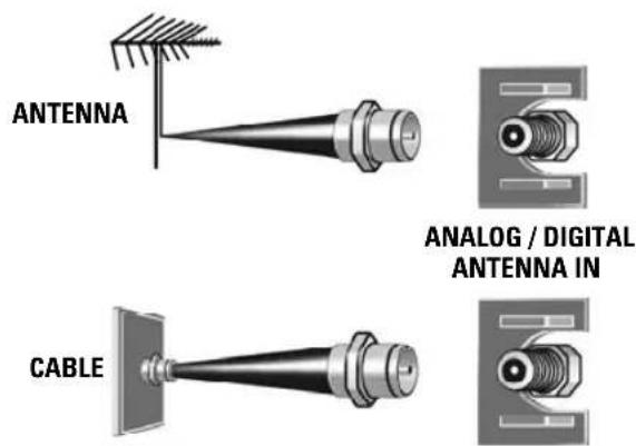
The tuner in this HDTV can receive:
• Digital and Analog off air signals from an antenna
- Analog or ClearQAM cable channels from a direct Cable TV connection.
GETTING STARTED
HDTV INPUT/OUTPUT REFERENCE
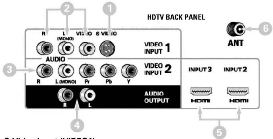
1 S-Video Input (VIDEO1)
NOTE: An S-Video connection will override a connection to the Video1 (yellow) input jack.
2 Composite AV Input (VIDEO1) – Yellow (Video), plus white and red (Audio) input jacks.
3 Component AV Input (VIDEO2) – Green (Y), blue (Pb), and red (Pr) Video inputs plus the white and red Audio inputs.
4 Stereo Audio Out (L/R) Jacks
5 HDMI (INPUT2 & 3) – An all digital AV interface accepting uncompressed video signals up to 1080p for the best picture possible.
6 Analog / Digital Antenna Input – Connect a 75 OHM cable from an antenna or direct Cable service.
7 Digital Audio Output (Coaxial)
8 AV Component Input (VIDEO3) – Green (Y), blue (Pb), and red (Pr) Video inputs plus the white and red Audio inputs.
NOTE: A Composite connection is possible via VIDEO INPUT3 using the Y (VIDEO) jack and the L/R audio jacks. (See Video 3 Setting on page 12.)
9 PC Input and Stereo Audio (Mini)
• MONITOR RGB (D-SUB)
• AUDIO R/L (Stereo Mini Jack)
NOTE: See page 18 for proper PC hookup and setup.
HDTV
SIDE PANEL
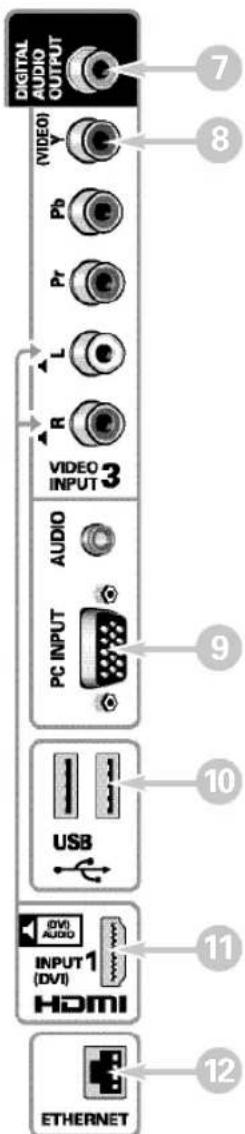
10 USB Input
View pictures stored in a USB flash drive.
11 HDMI (INPUT1) – An all digital AV interface accepting uncompressed video signals up to 1080p for the very best picture possible.
NOTE: A DVI connection is possible via the HDMI INPUT1 (DVI) using an appropriate adapter and the VIDEO3 Audio jacks for sound output.
12 ETHERNET Port
Hook up your HDTV to the internet with the use of an appropriate ethernet cable and a correct internet setup.
NOTE: Please refer to the cTV Guide for the proper connection to your Local Area Network (LAN).
3 AUDIO / VIDEO CONNECTIONS (SIDE PANEL)
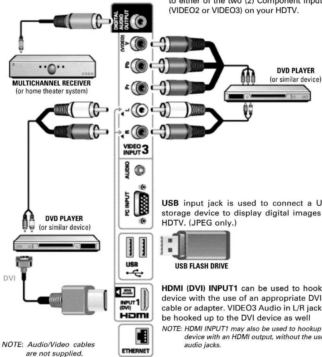
Digital Audio Output is used to output the HDTV's Audio through your home theater system.
Hook up the HDTV's Digital Audio Output to your home theater system's input with the use of a phono-type Digital Audio cable.
COMPONENT connections will accept SDTV, EDTV and HDTV video signals. Use them for great image quality from digital devices such as a DVD player or Video Game system.
Match your digital device's Component output jacks to either of the two (2) Component input jack sets (VIDEO2 or VIDEO3) on your HDTV.
flowchart
graph TD
    A["Digital Audio Output"] --> B["MULTICHANNEL RECEIVER (or home theater system)"]
    A --> C["VIDEO1"]
    A --> D["VIDEO2 or VIDEO3"]
    A --> E["Video Player (or similar device)"]
    A --> F["Video3 INPUT 3"]
    A --> G["USB Flash Drive"]
    A --> H["DVD Player (or similar device)"]
    A --> I["DVI"]
    A --> J["USB Input jack is used to connect a U storage device to display digital images HDTV. (JPEG only)."]
    A --> K["HDMI (DVI) INPUT1 can be used to hook device with the use of an appropriate DVI cable or adapter. VIDEO3 Audio in L/R jacks be hooked up to the DVI device as well"]
    A --> L["NOTE: HDMI INPUT1 may also be used to hookup device with an HDMI output, without the use of audio jacks."]
    A --> M["NOTE: Audio/Video cables are not supplied."]
USB input jack is used to connect a USB mass storage device to display digital images on your HDTV. (JPEG only.)
HDMI (DVI) INPUT1 can be used to hookup a DVI device with the use of an appropriate DVI to HDMI cable or adapter. VIDEO3 Audio in L/R jacks need to be hooked up to the DVI device as well
NOTE: HDMI INPUT1 may also be used to hookup any digital device with an HDMI output, without the use of the L/R audio jacks.
3 AUDIO / VIDEO CONNECTIONS (BACK PANEL)
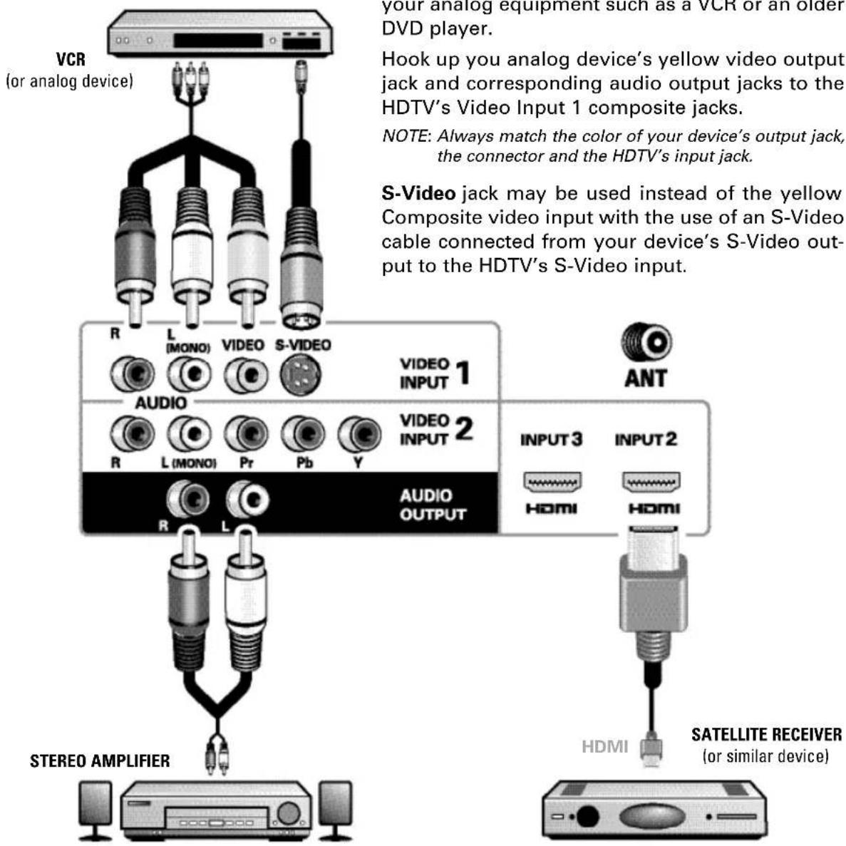
Audio Output L/R are used to hookup an external stereo Amplifier. Connect your home stereo's input jacks to the HDTV's Audio Output jacks with a pair of audio red and white connectors.
NOTE: Do not connect external speakers directly to the HDTV.
Use HDMI INPUT1, 2 & 3 to hookup HD digital devices such as a Blu-ray player, HD Cable Box, HD Satellite Receiver or Video-game System.
Connect your digital device's HDMI output to any of the three (3) HDMI inputs on your HDTV with the use of an HDMI cable.
GETTING STARTED (CONTINUED)
4 INITIAL CHANNEL SEARCH

Before proceeding, please make sure to hook up your antenna or cable connection and all AV equipment correctly to your HDTV.
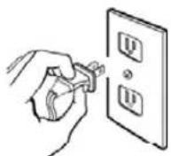
PLUG IN AC POWER CORD
120V AC, 60Hz
TURN ON TV (PRESS POWER BUTTON)
Wait for on-screen instructions to set an Initial Energy Saving Mode, and perform an Initial Channel/Signal Search.
TV SET LOCATION SELECTION:
Select "Home Mode" by pressing the CH▼ key to set the HDTV's backlight to an Energy Star qualified level, or select "Store Mode" by pressing CH▲ to set the backlight to a retail display level.
CHANNEL AND AV SIGNAL SEARCH:
Press the CH▲▼ key to perform a channel search from an Antenna or a direct Cable connection, and a signal search from devices hooked up to the HDTV's AV input jacks.
ON SCREEN HELP (OPTIONAL)

Press the CH▼ key if you wish to access an on screen trouble shooting guide.
NOTE: On screen help is also accessible via the main menu.
CHANNEL AND SIGNAL SETUP SCREEN
The final setup screen displays analog and digital channels found as well as AV inputs detected. Pressing the CH▲▼ key finalizes the setup process.
NOTE: To repeat the initial setup process press VOL▼.
5 AV INPUT SELECTION
Press the INPUT key to select the correct AV input for the video source you wish to watch.
Please select the proper location for your TV, the display will be adjusted for best results.
- Press Channel UP for Store Mode.
- Press Channel DOWN for Home Mode.
Store mode is for the retail display setup. Home mode qualifies for ENERGY STAR.
INITIAL ENERGY SAVING MODE SCREEN
Please connect all antennas* and signals to the jacks and terminals. Make sure all of your equipment is switched on.
- Press Channel UP or DOWN for Channel/Signal search.
- Press VOLUME DOWN for On Screen Help.
• To avoid signal interference when searching for channels using an Indoor Antenna, place the antenna at least 3 feet away from TV.
INITIAL CHANNEL/SIGNAL SEARCH SETUP SCREEN
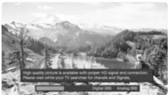
CHANNEL SEARCH PROGRESS SCREEN
Channel and Signal Setup:
Analog Channels...16
Digital Channels...24
Video 1...Yes
HDMI 1...Yes
Video 2...no
HDMI 2...no
Video 3...no
HDMI 3...no
Press Channel UP or DOWN to exit the Setup process. Press VOLUME DOWN to repeat the process.
If you are having problems, call us toll-free at 1-800-877-5032
CHANNEL/SIGNAL LIST SCREEN
Need help?
www.sanyoctv.com
1-877-864-9604
- POWER Key—Turns your HDTV On or Off.
- ECO Key—Modifies the Energy Saver level (see page 13.)
- AUDIO Key—Selects the desired Audio mode. Stereo, Mono, or SAP (when available.)
- ON TIMER Key—Displays the current switch on time (see Clock Timer on page 14.)
- CAPTION Key—Cycles through the available Caption modes.
- RESET Key—Pressing it twice restores your HDTV to its factory settings. All user customized settings will be cleared.
- SLEEP Key—Displays the "Off" Timer. While Off Timer is on-screen, press the "0" key to Set the amount of time (in 30 minute increments) at which the HDTV will turn off.
- PIX SHAPE Key—Cycles through the available aspect ratios. The different settings either stretch, zoom, or fill the image on your screen. Bars may appear on top and bottom of your screen (or on left and right sides) depending on the broadcasted signal or program.
NOTE: Pix6-7 are setup as Pix1-2 in PC mode. Use of Pix6-7 in TV mode is not recommended. - INFO Key—Displays the Channel Information banner.
- NUMERICAL Keys—Select channels directly.
NOTE: For channels 100 and up, press and hold the first number, then enter the remaining two numbers. - (sub ch) Key —Allows for the direct selection of digital subchannels. For example: to select channel 39.1 press the 3, 9, —and 1 keys.
- INPUT Key—Selects the video source to view. Holding down the key displays the Input List.
- Volume +—Keys—Increases or decreases the audio level.
-
Channel ▲ ▼ Keys—Scan through the channels in the memory database.
-
MUTE Key—Mute or restore the sound.
- RECALL Key—Switch between current channel and last selected channel.
- NET@ Key—Shortcut key to select the Net input directly and display the Internet Entry screen.
- HDMI Key—Cycles through the HDMI inputs.
- USB Key—Selects the USB input directly.
- MENU Key—Displays or hides the on-screen menu.
- HELP Key—Displays on-screen Help menu.
- LiNKS Key—Show or hide the available widgets. Serves as a Home key for the content services when navigating the Net input.
- EXIT Key—Exits the on-screen menu. Return to the previous screen when navigating the Net input.
- Cursor ▲ (UP) ▼ (DOWN) keys—Move the on-screen cursor up and down.
- Cursor ◀ (LEFT) ▶ (RIGHT) keys—Move the on-screen cursor left and right.
- ENTER Key—Set or select the highlighted option on the screen.
The PLAY, PAUSE, STOP, REW, FF, W, T, CAMERA, and XACTI MENU keys control playback features on a Sanyo Xacti digital camera when the HDMI-CEC feature has been activated on both the HDTV and the Xacti camera (see HDMI Linking feature on page 12.)
NOTE: These playback keys may or may not react with other devices other than the Xacti camera.
Display the On Screen menu and use the CURSOR ▲▼ keys to select Channel / Input. Press ENTER.
Channel Search
Auto - Searches the detected mode, Cable or Air.
Cable - Searches for analog and unscrambled (ClearQAM) digital cable channels.
Air (Antenna) – Searches for analog and digital off-air channels.
Digital Add-On - Searches digital off-air channels adding newly found digital channels to the channel map database.
NOTE: Digital Add-On option is not available when the current mode is Cable.
Channel Scan Memory
Channel Scan Memory lists all Analog and Digital channels found. It also lists Analog channels that were not found, which can be added.
Use the CURSOR ▲▼ keys to move the channel select bar through all enabled and disabled channels, or use the CH ▲▼ keys to skip all disabled channels.
Press ENTER to enable or disable the selected channel.
NOTE: For information on local digital channels, visit www.antennaweb.org
IMPORTANT FACT: This HDTV maintains only one database of digital channels. Therefore, when you search for cable channels, the database of antenna digital channels will be deleted. You will only be able to receive those ClearQAM channels your cable company provides.
Input Setting
Input Setting feature allows the removal of unused inputs from the AV input loop.
Use the CURSOR ▲▼ keys to select an AV input. Press ENTER to disable (uncheck) or enable (check) the highlighted input.
NOTE: At least one input must and will remain enabled.
☐:Skip is for reference only.
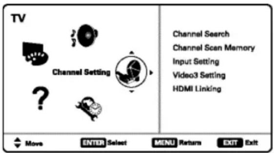
MAIN MENU SCREEN
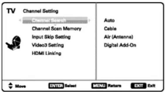
CHANNEL SETTING SCREEN
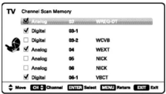
CHANNEL SCAN MEMORY SCREEN
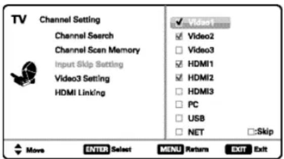
INPUT SETTING SCREEN
Use this feature to establish either a Component or Composite connection to the VIDEO INPUT 3 jacks on your HDTV.
Use the CURSOR ▲▼ keys to select the type of hook up that will be used in the Video3 input.
Press ENTER, a blue mark will appear next to the selected option.
HDMI Linking
NOTE: Designed for use with a Sanyo Xacti Digital Video/Movie Camera, and may not support all HDMI-CEC functions of other equipment.
Use the HDMI-CEC Function to enable or disable all available CEC functions.
HDMI Power ON Sync and Power OFF Sync enable specific features including the automatic power ON process and power OFF process.
Xacti-LINK
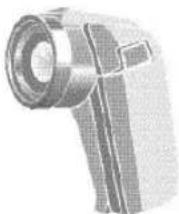
With a Sanyo Xacti Digital Video/Movie Camera hooked up to your HDTV's HDMI input, setting the HDMI-CEC Function to ON enables you the use of keys on your GXEB remote to operate your Xacti camera.
NOTE: The HDMI-CEC function of the Xacti camera must also be turned ON to enable the Xacti-Link.
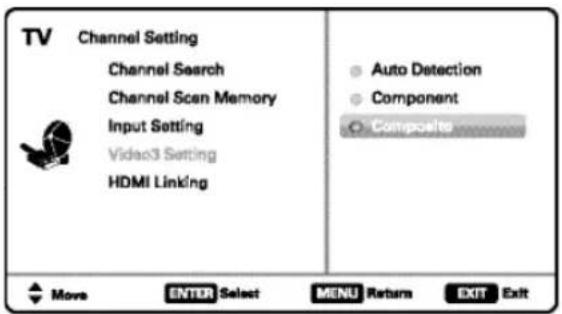
VIDEO3 SETTING SCREEN
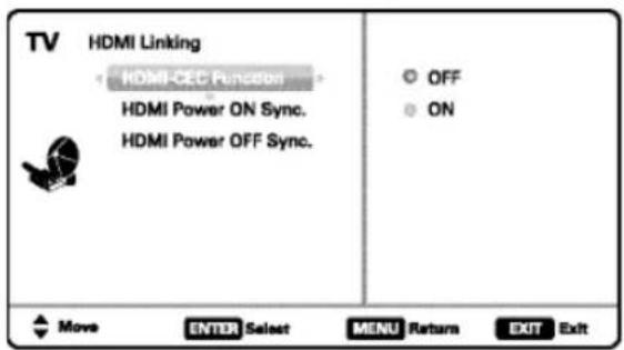
HDMI LINKING SCREEN
Display the On Screen menu and use the CURSOR ▲▼ keys to select Setup. Press ENTER.
Menu Language
Choose the language in which the On Screen menus will be displayed.
- English
- Español
- Français
Press ENTER on the desired language.
Digital Caption
Captioning is textual information transmitted along with the picture and sound. Turning Captioning ON (by pressing the CAPTION key during normal TV viewing) causes the HDTV to open these captions (digital or analog) and superimpose them on the screen.
NOTE: Local broadcasters decide which caption signals to transmit.
Use the CURSOR ▲▼ and ◀▶ keys to modify Font, Background, and Foreground of digital caption text.
Energy Setting
Use the Energy Saver and Light Sensor features found under Energy Setting to lower power consumption by controlling the LED backlight brightness levels.
Energy Saver – This settings control the LCD backlight brightness to reduce power consumption.
- Level 1: Energy Saver feature is off.
- Level 2: Low power consumption.
- Level 3: Lowest power consumption.
Press ENTER on the desired level.
NOTE: ECO key may also be used as a shortcut to modify the Energy Saver settings.
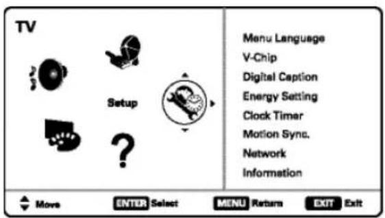
MAIN MENU SCREEN
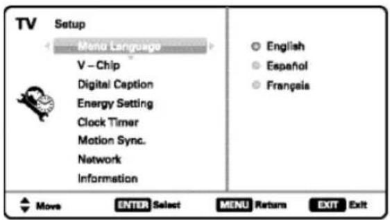
MENU LANGUAGE SCREEN
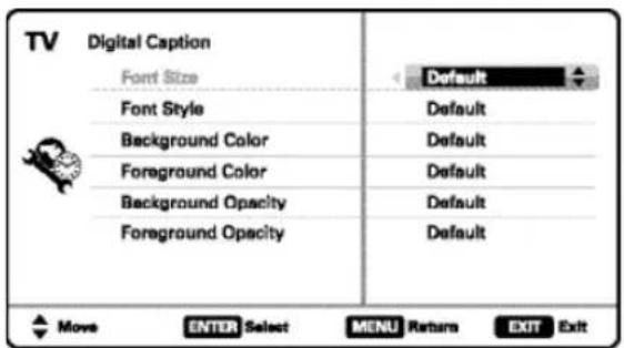
DIGITAL CAPTION SCREEN
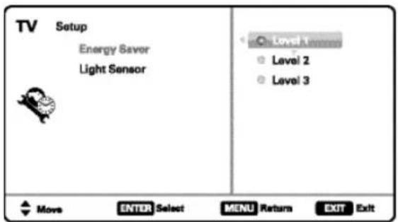
ENERGY SAVER SCREEN
Light Sensor – Detects ambient room light brightness and uses that reading to control the panel brightness level and picture parameters to reduce the HDTV's power consumption.
NOTE: When room lighting is dark, the panel brightness and/or the picture setting parameters such as brightness and cotrast are lowered. When room lighting is bright, parameters are affected opposite.
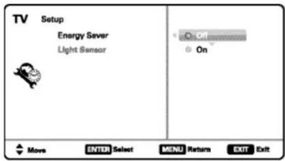
LIGHT SENSOR SCREEN
Clock Timer
This feature allows you to set a Current Time for your HDTV and enable a Switch On Time for the HDTV to turn on at a specific time of day.
When On Timer Function is set to ON, the TV will automatically turn on at the previously set Switch on Time.
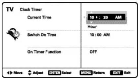
CLOCK TIMER SCREEN
Motion Sync
Your HDTV will display all signals at the refresh rate of 120Hz. Motion Sync is a special Frame Rate Converter feature that helps eliminate motion blur and film judder in scenes with fast action.
- On – Takes full advantage of your TV's refresh rate capabilities for the best picture quality.
- Off – Disables the Motion Sync feature.
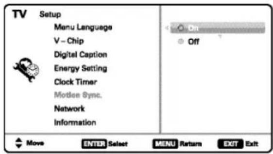
MOTION SYNC SCREEN
Use this feature to automatically block programs with content you deem as inappropriate for viewing by your children.
NOTE: This feature is designed to comply with the United States of America's FCC V-Chip regulations. Therefore, it may not function with broadcasts that originate in other countries.
ADJUSTING THE V-CHIP RATINGS
Select ON and press ENTER.
Select Adjust (Standard) and press ENTER.
Use the CURSOR ▲▼ and ◀▶ keys to navigate and the ENTER key to Block or Unblock a selected rating. A lock symbol will appear beside the selected rating option indicating that it is blocked.
NOTE: Blocking a rating will automatically block all higher ratings. Unblocking a rating automatically unblocks all lower ratings.
ADVANCED V-CHIP SYSTEM (RRT5)
RRT5 (V-Chip Regional Ratings 5) is an advanced V-Chip ratings system for digital channels that are received with an antenna.
When the HDTV detects compatible RRT5 data, it's downloaded & stored in memory, and the Setup V-Chip screen is then modified to show the Adjust (Advanced) option.
Use the CURSOR ▲▼ and ◀▶ keys to highlight the different options, and use the ENTER key to block or unblock the selected rating.
NOTE: There may be more ratings than can be displayed on one screen. When vertical scroll bars appear, press CURSOR ▲▼ to gain access to the additional ratings.
MORE INFORMATION
Additional information about MPAA (Motion Picture Association of America) and V-Chip rating can be found at: www.mpaa.org and www.v-chip.org, respectively.
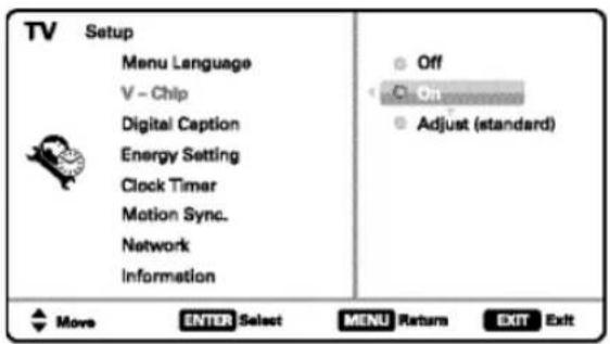
V-CHIP SETUP SCREEN
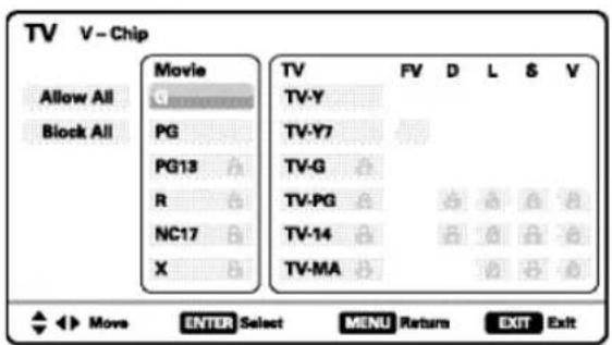
ADJUST (STANDARD) SCREEN
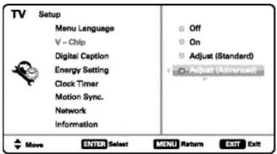
V-CHIP SETUP SCREEN WITH ADJUST (ADVANCED) OPTION
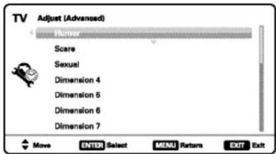
ADJUST (ADVANCED) SCREEN
Display the On Screen menu and use the CURSOR ▲▼ keys to select Picture. Press ENTER.
You may choose between Vivid, Mild, , and Standard, which have predetermined fixed picture parameter values, or choose the Manual option for customized personal settings.
NOTE: Each AV input can have its own picture mode (pre-determined or manual.) Current input's selected option is indicated by a blue marker.
MANUAL PICTURE SETTINGS
Manual parameters to adjust include:
• Color
- Tint
- Contrast
- Brightness
- Sharpness
• Dynamic Contrast
The Detailed Setting option allows for the adjustment of 7 additional parameters such as:
- Signal Balancer
- Noise Reduction
- White Balance
• Vertical Sharpness
- Edge Enhancer
• H-Size
- V-Size
NOTE: Default Picture option returns all picture parameters to their original factory settings.
ADJUSTING A PICTURE SETTING
Use the CURSOR ▲▼ keys to highlight the picture parameter you wish to adjust. Press the ENTER key to enter the value adjustment screen. Modify the selected parameter's value by pressing the CURSOR ◀▶ keys.
NOTE: CURSOR ▲▼ keys select the next/previous parameter without returning to the previous menu screen.
Once adjustments are complete, press the EXIT key to return to normal TV viewing.
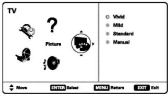
MAIN MENU SCREEN
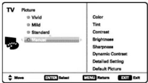
PICTURE SCREEN (MANUAL)
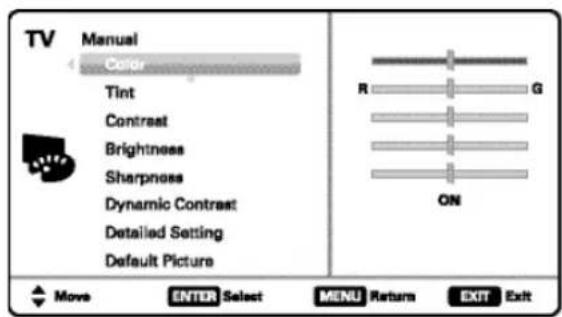
PARAMETER SELECTION SCREEN


VALUE ADJUSTMENT SCREEN EXAMPLES
Display the On Screen menu and use the CURSOR ▲▼ keys to select Sound. Press ENTER.
Choose an option for your sound settings:
Auto – Sound settings are linked to the current Picture option and parameters are adjusted accordingly.
Dynamic, Mild, Standard - 3 different predetermined sound parameters not linked with any Picture option.
MANUAL SOUND SETTINGS
The Manual option provides different parameters that can be personally adjusted:
- Bass
- Treble
- Detailed Setting
- 4-Band Equalizer: Personalize audio highs and lows.
NOTE: Default Sound option returns all sound parameters to their original factory settings.
ADJUSTING A SOUND SETTING
Use the CURSOR ▲▼ keys to highlight the sound parameter you wish to adjust. Press the ENTER key to enter the value adjustment screen. Modify the selected parameter's value by pressing the CURSOR ◀▶ keys.
NOTE: CURSOR ▲▼ keys select the next/previous parameter without returning to the previous menu screen.
Once adjustments are complete, press the EXIT key to return to normal TV viewing.
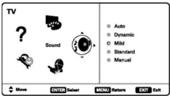
MAIN MENU SCREEN
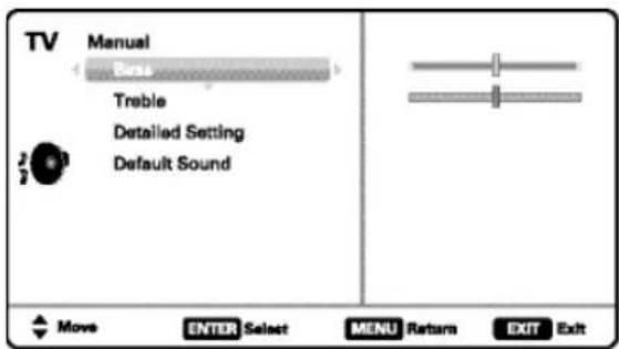
MANUAL PARAMETER SCREEN
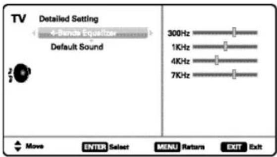
DETAILED SETTING SCREEN

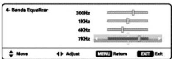
VALUE ADJUSTMENT SCREEN EXAMPLES
PC INPUT
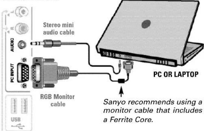
Use your HDTV as a computer monitor by hooking up your PC or Laptop to the TV with the use of an appropriate monitor cable (not included.)

Before connecting any cables, disconnect the AC power cords of both the HDTV and PC from the AC outlets.

Power on the HDTV and any other peripheral equipment before powering on the computer.
To avoid an "Out of Range" condition please set your PC's output resolution to one compatible with your HDTV. See PC Resolution chart on page 3.
NOTE: If computer has only DVI Output, a DVI to RGB adapter will be required, or, a DVI to HDMI cable and RCA audio cables (see HDMI (DVI) INPUT1 on page 7.)
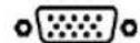
RGB OUTPUT
JACK
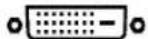
DVI OUTPUT
JACK
HDTV SIDE PANEL
Laptop Display
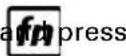
When using your Sanyo HDTV to display a Laptop's screen display, holding down the Fn (or FN) key while pressing the appropriate function key (F5, F7, F8, etc) should cycle through different display modes between the laptop and the HDTV.
Modes may include displaying only on the laptop screen, on both the laptop and the HDTV, or displaying only on the HDTV.
Hold down
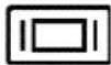
NOTE: Fn key and function key symbols on the laptop's keyboard may vary from one brand to another.
PC Setting
Auto Adjustment – Automatically adjusts display position, dot clock and phase.
Dot Clock – Adjust the Dot frequency to match your computer's Dot frequency.
Phase - Adjust this parameter when the picture appears to flicker or is blurred.
H-Position – Move the image horizontally
V-Position - Move the image vertically
Power Saving - Enable the HDTV to turn to Standby Mode when computer is not in use.
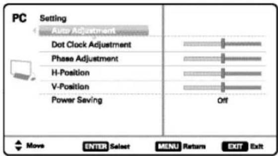
PC SETTING SCREEN
PC Picture and Sound
Standard - Sets predetermined values to the Picture or Sound parameters.
Manual - Adjust Contrast, Brightness, and Color Temperature screen settings, and the Bass and Treble audio settings.
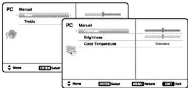
PC PICTURE AND SOUND SCREENS
NOTE: These settings do not affect normal TV viewing.
USB INPUT
PHOTO VIEWER
View pictures on your HDTV with the use of a USB mass storage device (not included.)
Any of the two USB inputs on your HDTV may be used.
NOTE: When two devices are hooked up, only the first one is recognized and available as an input.
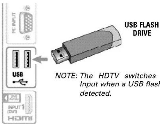
USING THE PHOTO VIEWER
Press ENTER on a thumbnail photo to enable the Rotate, Full View and Start Slideshow functions.
Once in Full View mode:
Use the CURSOR ◀▶ keys to change picture.
Press ENTER to show the full view options menu.
SLIDE SHOW
In the Slideshow Setup menu you may turn the Shuffle and Quick Change options ON or OFF.
Press ENTER on Start Slideshow from the Thumbnail View Screen or from the full view options menu to start the slideshow from the current picture.
JPEG VIEWER USB MENU
Press MENU when in Full View or Slideshow mode to display the USB On screen menu.
Picture Setting - Adjust Color, Tint, Contrast, Brightness, Sharpness and Dynamic Contrast.
NOTE: Picture Settings are separate configurations from the settings in TV and AV inputs.
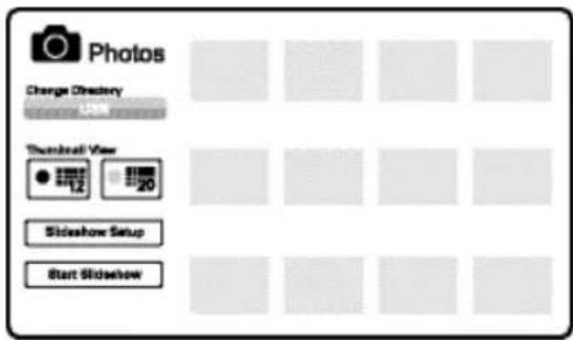
THUMBNAIL VIEW SCREEN
NOTE: A thumbnail hide icon will appear if a picture cannot be decoded or if no thumbnail data is available.
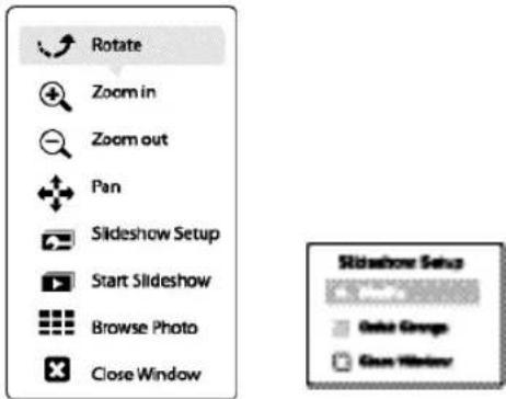
FULL VIEW
OPTIONS MENU
SLIDE SHOW
SETUP MENU
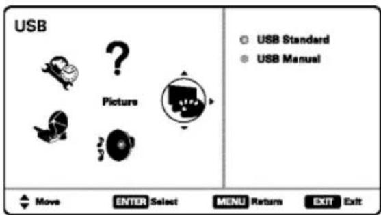
USB MAIN MENU SCREEN
ONE-YEAR LIMITED PARTS AND LABOR WARRANTY
THIS LIMITED PARTS AND LABOR WARRANTY IS VALID ONLY ON SANYO TELEVISIONS PURCHASED AND USED IN THE UNITED STATES OF AMERICA, CANADA, AND PUERTO RICO, EXCLUDING ALL OTHER U.S. TERRITORIES AND PROTECTORATES. THIS LIMITED WARRANTY APPLIES ONLY TO THE ORIGINAL RETAIL PURCHASER, AND DOES NOT APPLY TO PRODUCTS USED FOR INDUSTRIAL OR COMMERCIAL PURPOSES.
WARRANTY APPLICATION
FOR ONE YEAR from the date of original retail purchase Sanyo Manufacturing Corporation (SMC) warrants this TV to be free from manufacturing defects in materials and workmanship under normal use and conditions for parts and labor.
For the FIRST 90 DAYS from the date of original retail purchase, Sanyo Manufacturing Corporation will replace any defective TV via exchange at the retailer. To ensure proper warranty application, keep the original-dated-sales receipt for evidence of purchase. Return the defective TV to the retailer along with the receipt and the included accessories, such as the remote control. The defective TV will be exchanged for the same model, or a replacement model of equal value, if necessary. Replacement model will be contingent on availability and at the sole discretion of Sanyo Manufacturing Corporation.
THE FOREGOING WARRANTY IS EXCLUSIVE AND IN LIEU OF ALL OTHER WARRANTIES OF MERCHANTABILITY OR FITNESS FOR A PARTICULAR PURPOSE.
OBLIGATIONS
For one year from the date of purchase, Sanyo Manufacturing Corporation warrants this product to be free from defects in material and workmanship under normal use and conditions. During the first 90 days under this warranty for any manufacturing defect or malfunction Sanyo Manufacturing Corporation will provide a new TV via exchange at the retailer.
HOW TO MAKE A CLAIM UNDER THIS WARRANTY
Please call 1-877-864-9604. Please be prepared to give us the television's model number and serial number when you call. The model number and serial number are printed on a label attached to the back of the unit.
For customer assistance, call toll free 1-877-864-9604.
Hours of operation: Monday – Friday 7:30 AM - 7:00 PM CST
This warranty expresses specific contractual rights; retail purchasers may have additional statutory rights which vary from state to state.
(EFFECTIVE: March 1, 2007)
Your Sanyo HDTV is registered at the time of purchase, please keep sales receipt for future reference.
For your protection in the event of theft or loss of this product, please fill in the information requested below and KEEP IN A SAFE PLACE FOR YOUR OWN PERSONAL RECORDS.
Model No. Date of Purchase
Serial No. ____ Purchase Price ____
(Located on back of unit)
Where Purchased

Sanyo Manufacturing Corp.
3333 Sanyo Road, Forrest City, AR 72335
PRECAUCIÓN
natural_image
Illustration of a hand pointing at a button on a computer monitor (no text or symbols present)natural_image
Diagram of a hand operating a device with control panel and grid lines (no text or symbols)natural_image
Diagram of four connected audio/video connectors with a monitor on top (no text or symbols)Please select the proper location for your TV, the display will be adjusted for best results.
● Press Channel UP for Store Mode.
- Press Channel DOWN for Home Mode.
Store mode is for the retail display setup. Home mode qualifies for ENERGY STAR.
Please connect all antennas* and signals to the jacks and terminals. Make sure all of your equipment is switched on.
- Press Channel UP or DOWN for Channel/Signal search.
- Press VOLUME DOWN for On Screen Help.
• To avoid signal interference when searching for channels using an indoor Antenna, place the antenna at least 3 feet away from TV.
Channel and Signal Setup:
Analog Channels...16
Video 1...Yes
Video 2...no
Video 3...no
Digital Channels...24
HDMI 1...Yes
HDMI 2...no
HDMI 3...no
Press Channel UP or DOWN to exit the Setup process. Press Volume DOWN to repeat the process.
If you are having problems, call us toll-free at 1-800-877-5032
natural_image
Close-up of a handheld electronic device (no visible text or symbols)V - Chip (Control paternal)
Sanyo Manufacturing Corp. 3333 Sanyo Road, Forrest City, AR 72335
¿Necesita ayuda?

www.sanyoctv.com

1-877-864-9604
For assistance:
Visit our Web site:
www.sanyoctv.com
or call toll free:
1-800-877-5032
We'll be glad to Help
SANYO
Sanyo Manufacturing Corp.
3333 Sanyo Road, Forrest City, AR 72335
Printed in Mexico SMC, May 2010
- CAUTION
- RISK OF ELECTRIC SHOCK DO NOT OPEN!
- IMPORTANT SAFETY INSTRUCTIONS
- FCC INFORMATION
- TRADEMARKS
- CONTENTS
- SPECIFICATIONS
- Please read before operating your HDTV!
- PROTECTING THE SCREEN
- HANDLING PRECAUTIONS
- POSITIONING THE HDTV
- STAND REMOVAL AND WALL MOUNTING (OPTIONAL)
- Mounting screws measurements:
- GETTING STARTED
- BATTERY INSTALLATION
- ANTENNA CONNECTION FOR OFF-AIR SIGNALS OR CABLE
- The tuner in this HDTV can receive:
- HDTV INPUT/OUTPUT REFERENCE
- S-Video Input (VIDEO1)
- PC Input and Stereo Audio (Mini)
- USB Input
- ETHERNET Port
- AUDIO / VIDEO CONNECTIONS (SIDE PANEL)
- AUDIO / VIDEO CONNECTIONS (BACK PANEL)
- GETTING STARTED (CONTINUED)
- INITIAL CHANNEL SEARCH
- PLUG IN AC POWER CORD
- TURN ON TV (PRESS POWER BUTTON)
- TV SET LOCATION SELECTION:
- CHANNEL AND AV SIGNAL SEARCH:
- ON SCREEN HELP (OPTIONAL)
- CHANNEL AND SIGNAL SETUP SCREEN
- AV INPUT SELECTION
- INITIAL ENERGY SAVING MODE SCREEN
- INITIAL CHANNEL/SIGNAL SEARCH SETUP SCREEN
- CHANNEL SEARCH PROGRESS SCREEN
- CHANNEL/SIGNAL LIST SCREEN
- Channel Search
- Channel Scan Memory
- Input Setting
- HDMI Linking
- Xacti-LINK
- Menu Language
- Digital Caption
- Energy Setting
- Clock Timer
- Motion Sync
- ADJUSTING THE V-CHIP RATINGS
- ADVANCED V-CHIP SYSTEM (RRT5)
- MORE INFORMATION
- MANUAL PICTURE SETTINGS
- ADJUSTING A PICTURE SETTING
- MANUAL SOUND SETTINGS
- ADJUSTING A SOUND SETTING
- PC INPUT
- To avoid an "Out of Range" condition please set your PC's output resolution to one compatible with your HDTV. See PC Resolution chart on page 3.
- Laptop Display
- PC Setting
- PC Picture and Sound
- USB INPUT
- PHOTO VIEWER
- USING THE PHOTO VIEWER
- SLIDE SHOW
- JPEG VIEWER USB MENU
- ONE-YEAR LIMITED PARTS AND LABOR WARRANTY
- WARRANTY APPLICATION
- OBLIGATIONS
- HOW TO MAKE A CLAIM UNDER THIS WARRANTY
- PRECAUCIÓN
- V - Chip (Control paternal)
Brand : SANYO
Model : DP55360
Category : Television