
NX-740 - Radio KENWOOD - Free user manual and instructions
Find the device manual for free NX-740 KENWOOD in PDF.


| Product Type | VHF/UHF Digital Transceiver |
| Brand | Kenwood |
| Model | NX-740 (H/HV variants) |
| Frequency Band | VHF: 136-174 MHz / UHF: 400-470 MHz (depending on model) |
| Power Supply | 13.6 V DC, negative ground |
| Current Consumption | <15 A (transmit), <2 A (receive) approx. |
| Dimensions (approx.) | 140 x 40 x 160 mm (5.5 x 1.6 x 6.3 in) |
| Weight (approx.) | 1.1 kg (2.4 lb) |
| RF Output Power | 25 W (VHF/UHF typical, subject to dealer programming) |
| Modulation | 4 Level FSK (NXDN) / FM (Analog) |
| Signaling Systems | QT/DQT, RAN, NXDN ID, DTMF, 2-Tone, FleetSync, MDC-1200 |
| Key Functions | Scan, Priority Scan, Emergency, Lone Worker, Talk Around, Scrambler/Encryption, Stun/Revive, Public Address |
| Connectors | ACC (D-SUB 15), External Speaker (3.5 mm), Microphone (8-pin), Antenna (50 Ω), DC Input |
| Supplied Accessories | DC power cable with fuses, mounting bracket, screw set, microphone (KMC-30/KMC-35), microphone hanger, instruction manual |
| Safety Certifications | FCC Part 15 Class B, meets RF exposure guidelines |
| Operating Temperature | -20°C to +60°C (-4°F to +140°F) |
| Maintenance | Clean with dry cloth; do not use harsh chemicals |
| Service | Refer to qualified technician only |
Frequently Asked Questions - NX-740 KENWOOD
User questions about NX-740 KENWOOD
0 question about this device. Answer the ones you know or ask your own.
Ask a new question about this device
Download the instructions for your Radio in PDF format for free! Find your manual NX-740 - KENWOOD and take your electronic device back in hand. On this page are published all the documents necessary for the use of your device. NX-740 by KENWOOD.
USER MANUAL NX-740 KENWOOD
NEXEDGE
VHF DIGITAL TRANSCEIVER
NX-740H NX-740HV
UHF DIGITAL TRANSCEIVER
NX-840H NX-840HU
JVCKENWOOD Corporation
B5A-0031-20 (K)

Terminal Descriptions
ACC (D-SUB 15 Pin Connector)
| Pin No. | Name I/O Description | Specification | ||
| 1 SB | O DC Power (Switched) | B) Output 13.6 V ±15% Max. 1 A | ||
| 2 IGN | I Igintion Signal Input | Min. Input: 10.8 VMax. Input: 16.0 V | ||
| 3 SP2 | /PA O Loudspeaker Output/ Public Address Output 4 Ω | |||
| 4 | DETO | O | RX Detected Audio Output | 280 mV _p-p (typ.) |
| 5 | DATAI | I | TX Data Input | 100 kΩ |
| 6 | FNC1/ TXD | I/O | Programmable/ PC Serial Data from Radio | High Impedance |
| 7 | FNC2/ RXD | I/O | Programmable/ PC Serial Data to Radio | High Impedance |
| 8 | FNC3 | I/O | Programmable | High Impedance |
| 9 | FNC4 | I/O | Programmable | High Impedance |
| 10 | FNC5 | I/O | Programmable | High Impedance |
| 11 | FNC6 | I/O | Programmable | High Impedance |
| 12 | 50MC | O | DC Power Output | 5 V, Max 100 mA |
| 13 | HR1 | I | Horn Alert Signal Input | Max 2 A |
| 14 | HR2 | O | Horn Alert Signal Output | Max 2 A |
| 15 | GND | — | Ground | Ground |
Speaker Jack (3.5 mm Phone Jack) 4 W/ 4 Ω
| Pin No. | Name I/O Description | Specification | ||
| 1 | SPO | O | External Speaker Output | 4 Ω |
| 3 | GND | — | Ground | Ground |
DC Input Connector
| Pin No. | Name I/O Description | Specification | |
| Red | B | I DC Power Input | 13.6 V ±15% |
| Black | GND | I Ground | Ground |
Microphone Jack
| Pin No. | Name I/O Description | Specification | ||
| 1 | MBL | O | MIC Backlight Control | High Impedance |
| 2 SB | O DC Power (Switched) | B) Output 13.6 V ±15% | ||
| 3 | GND | — | Ground | Ground |
| 4 | PTT/ TXD | I/O | PTT/ PC Serial Data from Radio | High Impedance |
| 5 | ME | — | Mic Ground | Ground |
| 6 MIC | I Mic Signal | Input | 600 Ω | |
| 7 HOOK/ RXD | I Hook/ PC | Serial Data to Radio | High Impedance | |
| 8 | DM | I/O | Mic Data Detection | High Impedance |
Antenna Terminal
50 Ω impedance
THANK YOU
We are grateful you have chosen KENWOOD for your personal mobile applications.
This instruction manual covers only the basic operations of your mobile radio. Ask your dealer for information on any customized features they may have added to your radio.
NOTICES TO THE USER
◆ Government law prohibits the operation of unlicensed transmitters within the territories under government control.
◆ Illegal operation is punishable by fi ne and/or imprisonment.
◆ Refer service to qualified technicians only.
SAFETY: It is important that the operator is aware of, and understands, hazards common to the operation of any transceiver.

WARNING
◆ EXPLOSIVE ATMOSPHERES (GASES, DUST, FUMES, etc.)
Turn OFF your transceiver while taking on fuel or while parked in gasoline service stations. Do not carry spare fuel containers in the trunk of your vehicle if your transceiver is mounted in the trunk area.
◆ INJURY FROM RADIO FREQUENCY TRANSMISSIONS
Do not operate your transceiver when somebody is either standing near to or touching the antenna, to avoid the possibility of radio frequency burns or related physical injury.
◆ DYNAMITE BLASTING CAPS
Operating the transceiver within 500 feet (150 m) of dynamite blasting caps may cause them to explode. Turn OFF your transceiver when in an area where blasting is in progress, or where "TURN OFF TWO-WAY RADIO" signs have been posted. If you are transporting blasting caps in your vehicle, make sure they are carried in a closed metal box with a padded interior. Do not transmit while the caps are being placed into or removed from the container.
One or more of the following statements may be applicable:
FCC WARNING
This equipment generates or uses radio frequency energy. Changes or modifications to this equipment may cause harmful interference unless the modifications are expressly approved by the party responsible/JVC KENWOOD. The user could lose the authority to operate this equipment if an unauthorized change or modification is made.
INFORMATION TO THE DIGITAL DEVICE USER REQUIRED BY THE FCC
This equipment has been tested and found to comply with the limits for a Class B digital device, pursuant to Part 15 of the FCC Rules. These limits are designed to provide reasonable protection against harmful interference in a residential installation.
This equipment generates, uses and can generate radio frequency energy and, if not installed and used in accordance with the instructions, may cause harmful interference to radio communications. However, there is no guarantee that the interference will not occur in a particular installation. If this equipment does cause harmful interference to radio or television reception, which can be determined by turning the equipment off and on, the user is encouraged to try to correct the interference by one or more of the following measures:
- Reorient or relocate the receiving antenna.
- Increase the separation between the equipment and receiver.
- Connect the equipment to an outlet on a circuit different from that to which the receiver is connected.
- Consult the dealer for technical assistance.
The AMBE+2 ^™ voice coding Technology embodied in this product is protected by intellectual property rights including patent rights, copyrights and trade secrets of Digital Voice Systems, Inc. This voice coding Technology is licensed solely for use within this Communications Equipment. The user of this Technology is explicitly prohibited from attempting to extract, remove, decompile, reverse engineer, or disassemble the Object Code, or in any other way convert the Object Code into a human-readable form. U.S. Patent Nos. #5,826,222, #5,754,974, #5,701,390, and #5,715,365.
Firmware Copyrights
The title to and ownership of copyrights for fi rmware embedded in KENWOOD product memories are reserved for JVC KENWOOD Corporation.
PRECAUTIONS
Observe the following precautions to prevent fire, personal injury, and transceiver damage.
- Do not attempt to configure the transceiver while driving; it is too dangerous.
- Do not disassemble or modify the transceiver for any reason.
- Do not expose the transceiver to long periods of direct sunlight, nor place it near heating appliances.
- If an abnormal odor or smoke is detected coming from the transceiver, switch the transceiver power off immediately, and contact your KENWOOD dealer.
- Use of the transceiver while you are driving may be against traffic laws. Please check and observe the vehicle regulations in your area.
- Do not use options not specified by KENWOOD.

CAUTION
The transceiver operates in 12 V negative ground systems only! Check the battery polarity and voltage of the vehicle before installing the transceiver.
◆ Use only the supplied DC power cable or a KENWOOD optional DC power cable.
◆ Do not cut and/or remove the fuse holder on the DC power cable.

WARNING
For passenger safety, install the transceiver securely using the supplied mounting bracket and screw set so the transceiver will not break loose in the event of a collision.
CONTENTS
GETTING STARTED....1
GETTING ACQUAINTED 3
PROGRAMMABLE FUNCTIONS 6
BASIC OPERATIONS 7
NXDN 8
SCAN 8
DTMF CALLS....9
SIGNALING.... 10
FleetSync: ALPHANUMERIC 2-WAY PAGING FUNCTION .... 11
ADVANCED OPERATIONS.... 12
Note: The following instructions are for use by your KENWOOD dealer, an authorized KENWOOD service facility, or the factory.
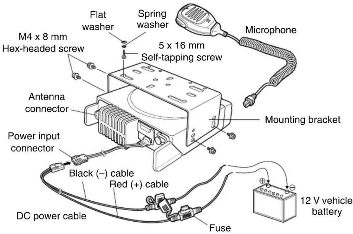
SUPPLIED ACCESSORIES
Carefully unpack the transceiver. We recommend that you identify the items listed below before discarding the packing material. If any items are missing or have been damaged during shipment, file a claim with the carrier immediately.
DC power cable (with fuses)....1
• 15 A fuse ....2
Mounting Bracket 1
Screw set
- 5 x 16 mm self-tapping screw. 4
- M4 x 8 mm Hex-headed screw with washer.... 4
- Spring washer .... 4
- Flat washer....4
Microphone (with cable)
KMC-30 (NX-740H/ NX-840H)....1
• KMC-35 (NX-740HV/ NX-840HU) ..... 1
Microphone hanger (with 4 x 16 mm self-tapping screws) .... 1
Instruction manual 1
PREPARATION

WARNING
Various electronic equipment in your vehicle may malfunction if they are not properly protected from the radio frequency energy which is present while transmitting. Typical examples include electronic fuel injection, anti-skid braking, and cruise control. If your vehicle contains such equipment, consult the dealer for the make of vehicle and enlist his/her aid in determining if they will perform normally while transmitting.
■ Power Cable Connection

CAUTION
The transceiver operates in 12 V negative ground systems only! Check the battery polarity and voltage of the vehicle before installing the transceiver.
1 Check for an existing hole, conveniently located in the fi rewall, where the power cable can be passed through.
- If no hole exists, use a circle cutter to drill a hole, then install a rubber grommet.
2 Run the power cable through the fi rewall and into the engine compartment.
3 Connect the red lead to the positive (+) battery terminal and the black lead to the negative (−) battery terminal.
- Place the fuse as close to the battery as possible.
4 Coil the surplus cable and secure it with a retaining band.
- Be sure to leave enough slack in the cables so the transceiver can be removed for servicing while keeping the power applied.
■ Installing the Transceiver

WARNING
For passenger safety, install the transceiver securely using the supplied mounting bracket and screw set, so the transceiver will not break loose in the event of a collision.
Note: Before installing the transceiver, check how far the mounting screws will extend below the surface. When drilling mounting holes, be careful not to damage vehicle wiring or parts.
1 Mark the position of the holes in the dash, using the mounting bracket as a template. Using a 4.2 mm (5/32 inch) drill bit, drill the holes, then attach the mounting bracket using the supplied screws.
- Mount the transceiver within easy reach of the user and where there is sufficient space at the rear of the transceiver for cable connections.
2 Connect the antenna and the supplied power cable to the transceiver.
3 Slide the transceiver into the mounting bracket and secure it using the supplied hex-headed screws.
4 Mount the microphone hanger in a location where it will be within easy reach of the user.
- The microphone and microphone cable should be mounted in a place where they will not interfere with the safe operation of the vehicle.

CAUTION
When replacing the fuse in the DC power cable, be sure to replace it with a fuse of the same value. Never replace a fuse with one that is rated with a higher value.
GETTING ACQUAINTED
FRONT/ REAR PANEL
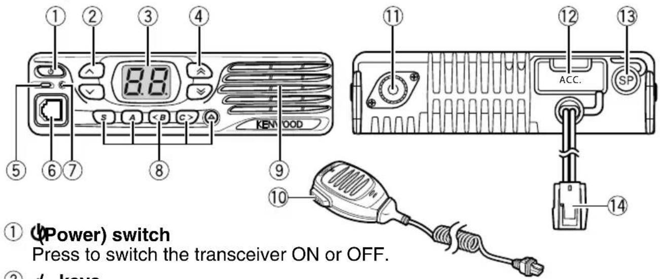
② 从 keys
Press to activate their programmable functions {page 6}.
③ Display
Refer to page 4.
④ 4 keys
Press to activate their programmable functions {page 6}.
⑤ TX/RX Indicator
Lights red while transmitting. Lights green while receiving a signal. Flashes orange when receiving an optional signaling call.
⑥ Microphone jack
Insert the microphone plug into this jack.
⑦ Status Indicator
Lights during a specified mode, based on dealer programming.
(Such as AUX, External Speaker, Horn Alert, Lone Worker, Priority Zone-Channel Select, Public Address, Scan Delete/Add, Scrambler/Encryption and Talk Around.)
⑧ S / A / / △keys
Press to activate their programmable functions {page 6}.
⑨ Speaker
Internal speaker.
⑩ PTT switch
Press this switch, then speak into the microphone to call a station.
⑪ Antenna connector Connect the antenna to this connector.
⑫ ACC connector
Connect the ACC to this connector, via the KCT-60.
⑬ External speaker jack
Connect an external speaker to this jack.
⑭ Power input connector
Connect the DC Power Cable to this connector.
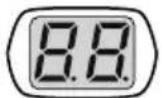
The display shows the zone/ channel number and the 2 dots show various modes of operation.
| Display Description Page | ||
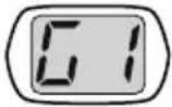 | Zone Display (Zone 1) | 7 |
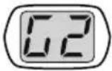 | Zone Display (Zone 2) | 7 |
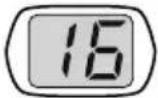 | Channel Display (Channel 16) | 7 |
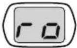 | Appears during Site Roaming. (ro) | - |
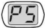 | Appears when switch the transceiver ON.The Transceiver Password function is programmed. (PS) | 6 |
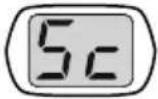 | Appears during Scan. (Sc) | 8 |
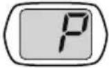 | The selected channel is the Priority channel. (P) | 9 |
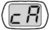 | Appears when a channel is added to the scan list. (cA) | 9 |
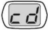 | Appears when a channel is removed from the scan list. (cd) | 9 |
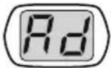 | Appears when the Autodial mode is on. (Ad) | 9 |
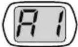 | Autodial list Display (Autodial list 1) | 9 |
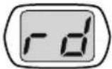 | Appears when the Redialing mode is on. (rd) | 9 |
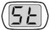 | Appears during the transceiver is stunned. (St) | 10 |
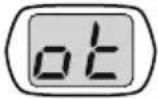 | Appears when the Operator Selectable Tone mode is on. (ot) | 11 |
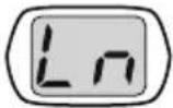 | Appears when the Lone Worker function is on. (Ln) | 12 |
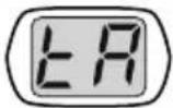 | Appears when the Talk Around function is on. (tA) | 12 |
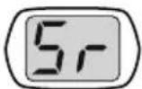 | Appears when the Scrambler function is on. (Sr) | 12 |
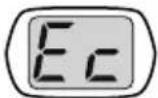 | Appears when the Encryption function is on. (Ec) | 12 |
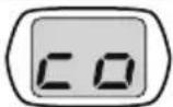 | Appears when the Scrambler/ Encryption code mode is on. (co) | 12 |
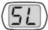 | Appears when the Squelch Level setting is on. (SL) | 13 |
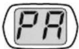 | Appears when the Public Address function is on. (PA) | 13 |
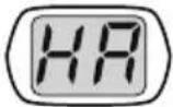 | Appears when the Horn Alert function is on. (HA) | 13 |
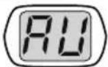 | Appears when the AUX function is on. (AU) | 14 |
The left and right dots on the display can be programmed to indicate specific modes of operation, as listed below.
- AUX
- External Speaker
- Horn Alert
-
Lone Worker
• Priority Zone-Channel -
Public Address
- Scan Delete/Add
- Scrambler/Encryption
- Talk Around
The right dot will blink during special operations, as listed below.
- Autodial
- Operator Selectable Tone
-
Channel Entry
-
Scrambler/Encryption Code
- Squelch Level
PROGRAMMABLE FUNCTIONS
The , , , , S, A,
- None
- Autodial ^1
- AUX
- Call 1/Call 2
- Channel Down
- Channel Entry
- Channel Up
- CW Message ^2
- Direct Zone-Channel
- Emergency ^3
- External Speaker
- Horn Alert
- LED Brightness
- Lone Worker
- Monitor
• Monitor Momentary - Operator Selectable Tone
- Paging Call
• Priority Zone-Channel Select - Public Address
- Scan
- Scan Delete/Add
- Scrambler/Encryption
- Scrambler/Encryption Code
- Send the GPS Data
- Squelch Level
- Squelch Off
- Squelch Off Momentary ^1
- Talk Around
- Volume Down
- Volume Up
- Zone Down
- Zone Up
^1 Available only for Analog operation.
^2 Available only for NXDN operation.
^3 Emergency can be programmed only on the ▲key.
SWITCHING POWER ON/OFF
Press ⏻ to switch the transceiver ON.
- A beep sounds and the display illuminates.
- If the Transceiver Password function is programmed, "PS" will appear on the display when the power is turned ON. Refer to "Transceiver Password", below.
Press 🏠 again to switch the transceiver OFF.
■ Transceiver Password
To enter the password:
1 Press to select a digit.
- When using an optional microphone with a keypad, simply enter the password digits and proceed to step 3.
2 Press C> to accept the entered digit and move to the next digit.
- Press A or # to delete an incorrect digit. Press and hold A or # to delete all digits.
- Repeat steps 1 and 2 to enter the entire password.
3 Press S or ✱ to confirm the password.
- If you enter an incorrect password, the transceiver remains locked.
ADJUSTING THE VOLUME
Press the [Volume Up] key to increase the volume. Press the [Volume Down] key to decrease the volume.
If Squelch Off has been programmed onto a key, you can use that function to listen to background noise while adjusting the volume level.
SELECTING A ZONE AND CHANNEL
Select the desired zone and channel using the keys programmed as [Zone Up]/[Zone Down] and [Channel Up]/[Channel Down].
- “G1” (Zone 1)/ “16” (Channel 16) appears on the display.
TRANSMITTING
1 Select your desired zone and channel.
2 Press the key programmed as [Monitor] or [Squelch Off] to check whether or not the channel is free.
- If the channel is busy, wait until it becomes free.
3 Press the PTT switch and speak into the microphone to transmit. Release the PTT switch to receive.
- For best sound quality at the receiving station, hold the microphone approximately 1.5 inches (3 cm \~ 4 cm) from your mouth.
RECEIVING
Select the desired zone and channel. If signaling has been programmed on the selected channel, you will hear a call only if the received signal matches your transceiver settings.
Note: Signaling allows your transceiver to code your calls. This will prevent you from listening to unwanted calls. Refer to "SIGNALING" on page 10 for details.
NXDN
NXDN is a general term for the NXDN wireless communication protocol which uses 4 Level FSK. Various data communications, including individual and group voice communications, Status calls, and GPS data transmission, are possible.
INDIVIDUAL/ GROUP CALLS
Each channel is set up with an individual or group ID list number. To make a call, select the channel with the ID list number you wish to call, then press the PTT switch to start the call.
- Your dealer may also have set Selcall on PTT for Individual or Group calls, allowing you to make an Individual or Group call when pressing the PTT switch.
- To page the target transceiver instead of initiating a voice call, press the key programmed as [Paging Call].
- If PTT Proceed tone is enabled, the Proceed tone will sound. After the tone ends, you can begin the call.
■ Receiving
When you receive an individual call, a ringing tone will sound. Respond to the call by pressing the PTT switch.
- If the auto reset timer expires before you respond to the call, the call will end. Your dealer can set the duration for the auto reset timer (default is 10 seconds).
When you receive a group call and the received group ID matches the ID set up on your transceiver, a ringing tone will sound and you can hear the caller's voice.
STATUS CALL
You can transmit your status (preset by your dealer) to the target transceiver by pressing the key programmed as [Call 1] or [Call 2], if they have been set up with an NXDN Status.
- Select the desired channel before sending the status call.
SCAN
Scan monitors for signals on the transceiver channels. While scanning, the transceiver checks for a signal on each channel and only stops if a matching signal is present.
To start/ stop scanning, press the key programmed as [Scan].
- “Sc” appears on the display during Scan.
- When a signal is detected, Scan pauses at that channel. The transceiver will remain on the busy channel until the signal is no longer present, at which time Scan resumes.
Note: To use Scan, there must be at least 2 channels added to the scanning sequence.
PRIORITY SCAN
If a Priority channel has been programmed, the transceiver will automatically change to the Priority channel when a call is received on that channel, even if call is being received on a normal channel.
- “P” appears on the display to indicate the Priority channel (depending on dealer setting).
TEMPORARY CHANNEL LOCKOUT
During scan, you can temporarily remove specific channels from the scanning sequence by pressing the key programmed as [Scan Delete/Add] while Scan is paused at the undesired channel.
- The channel is no longer scanned. However, when scanning is ended and restarted, the Scan settings return to normal.
SCAN DELETE/ ADD
You can add and remove channels to and from your scan list.
1 Select your desired channel.
2 Press the key programmed as [Scan Delete/Add] to remove a channel.
- When a channel is added to scan, "cA" appears on the display. When it is removed, "cd" appears on the display.
DTMF CALLS
Note: For keypad operation, you must use an optional microphone with a keypad.
MANUAL DIALING
1 Press and hold the PTT switch.
2 Enter the desired digits using the keypad.
- If Keypad Auto-PTT is enabled by your dealer, you do not need to press the PTT switch to transmit; you can make the call simply by pressing the keys.
AUTODIAL
Autodial allows you to quickly call DTMF numbers that have been programmed onto your transceiver.
1 Press the key programmed as [Autodial] or the * key.
- "Ad" appears on the display.
2 Press to select your desired Autodial list number, or enter the list number directly (1 \~ 9).
- “A1” (Autodial list 1) appears on the display.
3 Press the PTT switch to make the call.
REDIALING
1 Press the key programmed as [Autodial] or the key.
- "Ad" appears on the display.
2 Press the 0 key.
- "rd" appears on the display.
- If there is no data in the redial memory, an error tone will sound.
3 Press the PTT switch to make the call.
Note: Switching the transceiver power OFF clears the redial memory.
STUN
This function is used when a transceiver is stolen or lost. When the transceiver receives a call containing a stun code, the transceiver becomes disabled. The stun code is canceled when the transceiver receives a call with a revive code.
- “St” appears on the display while the transceiver is stunned.
SIGNALING
QUIET TALK (QT)/ DIGITAL QUIET TALK (DQT)
The Encoder/ Decoder function uses QT/ DQT to segregate talk groups, so users only hear calls from their own group.
RADIO ACCESS NUMBER (RAN)
RAN is a signaling system designed for digital radio communications. When a channel is set up with a RAN, squelch will only open when a call containing a matching RAN is received. If a call containing a different RAN is made on the channel you are using, you will not hear the call. This allows you to ignore (not hear) calls from other parties who are using the same channel.
NXDN ID
NXDN ID is an optional signaling system available only for digital communications.
DTMF
A DTMF PTT ID is included for dispatch operations or simple remote control applications. The DTMF decode capabilities include Selective Call ID, Transpond with ID, and "Wild Card" Group Calling.
2-TONE
2-tone Signaling opens the squelch only when your transceiver receives a call containing matching 2 tones.
FleetSync
Refer to "SELCALL (SELECTIVE CALLING)" on page 11.
MDC-1200
The following features are available with the built-in MDC signaling: PTT ID Encode, Emergency Encode, Stun/ Revive Decode, and Radio Check Decode.
Note: The transceiver cannot decode MDC-1200 if the FleetSync baud rate is 2400 bps.
OPERATOR SELECTABLE TONE (OST)
You can change the preset encode and decode tones for the selected channel. Up to 16 OST pairs can be pre-programmed by your dealer.
1 Select your desired channel.
2 Press the key programmed as [Operator Selectable Tone] or press and hold the ✳ key.
- "ot" appears on the display, followed by the current OST number.
3 Press to select the desired OST number.
4 Use the transceiver the same as in a regular call; press the PTT switch to transmit and release it to receive.
5 To exit OST mode and return to the preset encode and decode tones, press S.
FleetSync: ALPHANUMERIC 2-WAY PAGING FUNCTION
FleetSync is an Alphanumeric 2-way Paging Function and is a protocol owned by JVC KENWOOD Corporation.
Note: If set up by your dealer, your transceiver may use the MDC-1200 feature in place of FleetSync. MDC-1200 and FleetSync cannot be operated simultaneously.
SELCALL (SELECTIVE CALLING)
A Selcall is a voice call to a particular station or to a group of stations.
■ Transmitting
1 Select your desired zone and channel.
2 Press the PTT switch to transmit your PTT ID list and begin your conversation.
■ Receiving
If enabled by your dealer, an alert tone will sound and the LED will blink when a Selcall has been received.
To respond to the call, press the PTT switch and speak into the microphone.
■ Identifi cation Codes
An ID code is a combination of a 3-digit Fleet number and a 4-digit ID number. Each transceiver must have its own Fleet and ID number.
Note: The ID range may be limited by programming.
PAGING CALL
1 Select your desired zone and channel.
2 Press and hold the key programmed as [Paging Call] for 1 second to transmit your PTT ID list, to request a call.
GPS REPORT
If a GPS unit (NMEA-0183 format) is installed on your transceiver, you can press the key programmed as [Send the GPS data] to send your location data.
EMERGENCY CALLS
If your transceiver has been programmed with the Emergency function, you can make emergency calls.
1 Press and hold the key programmed as [Emergency].
- Depending on the delay time programmed into your transceiver, the length of time you must hold the [Emergency] key will vary.
- When the transceiver enters Emergency mode, the transceiver will change to the Emergency channel and begin transmitting based on how the transceiver is set up.
2 To exit Emergency mode, press and hold the [Emergency] key again.
- If the Emergency mode completes the preset number of cycles, Emergency mode will automatically end and the transceiver will return to normal.
■ Lone Worker Mode
Lone Worker Mode is a safety feature built into the transceiver. If the transceiver is not operated for a pre-programmed period of time, the transceiver will emit a tone and automatically enter Emergency operation.
Press the key programmed as [Lone Worker] to toggle the Lone Worker function ON or OFF.
- “Ln” appears on the display for 1 second.
TALK AROUND
During interruptions in service (such as a power failure), you can continue to communicate by using the Talk Around feature. Talk Around allows you to communicate directly with other transceivers without the use of a repeater, as long they are not too far away or there are no geographical obstacles in the way.
Press the key programmed as [Talk Around] to toggle the Talk Around function ON or OFF.
- "tA" appears on the display for 1 second.
SCRAMBLER/ ENCRYPTION
The Scrambler (analog) and Encryption (NXDN) function allows you to hold a conversation in complete privacy. When activated, any other party listening in on your channel will be unable to understand your conversation. Press this key to toggle the Scrambler/ Encryption function ON or OFF.
Press the key programmed as [Scrambler/Encryption] to toggle the Scrambler/Encryption function ON or OFF.
- "Sr"(analog)/ "Ec"(NXDN) appears on the display for 1 second.
You can change the scrambler/ encryption codes:
1 Press and hold the key programmed as [Scrambler/Encryption code] for 1 second.
- “co” (code) appears on the display, followed by the current scrambler/ encryption code.
2 Press to select your desired scrambler/ encryption code.
3 Press S or▲ to store the new setting.
- After changing your scrambler/ encryption code, be sure to inform all of your group members of the new code so they can also reset their transceivers. The scrambler/ encryption function will not work with transceivers set up with different scrambler/ encryption codes.
You can use the key programmed as [Monitor] or [Squelch Off] to listen to weak signals that you cannot hear during normal operation and to adjust the volume when no signals are present on your selected channel.
Your dealer can program a key with one of 4 functions:
- Monitor: Press to deactivate QT, DQT, DTMF, FleetSync Signaling, or NXDN. Press again to return to normal operation.
- Monitor Momentary: Press and hold to deactivate QT, DQT, DTMF, FleetSync Signaling, or NXDN. Release to return to normal operation.
- Squelch Off: Press to hear background noise. Press again to return to normal operation.
- Squelch Off Momentary: Press and hold to hear background noise. Release to return to normal operation.
■ Squelch Level
If a key has been programmed as [Squelch Level], you can readjust your transceiver's squelch level:
1 Press the key programmed as [Squelch Level].
- “SL” appears on the display, followed by the current squelch level.
2 Press to select the desired squelch level from 0 to 9.
3 Press S or ▲ to store the new setting.
PUBLIC ADDRESS (PA)
The PA system can only be used with an optional relay unit and external speaker.
1 Press the key programmed as [Public Address] to activate the Public Address function.
- “PA” appears on the display for 1 second.
2 Press and hold the PTT switch, then speak into the microphone to make your address through the external speaker.
3 Press the [Public Address] key again to exit Public Address.
HORN ALERT
The Horn Alert function can only be used with an optional relay unit.
Press the key programmed as [Horn Alert] to toggle the Horn Alert function ON or OFF.
- "HA" appears on the display for 1 second.
The Time-out Timer is used to prevent you from using a channel for an extended duration. If you continuously transmit for a preset time, the transceiver will stop transmitting and a warning tone will sound. Release the PTT switch to stop the tone.
AUXILIARY PORT
Press the key programmed as [AUX] to activate the auxiliary port. The auxiliary port is used with optional boards.
- "AU" appears on the display for 1 second.
DISPLAY BRIGHTNESS
You can cycle the display brightness between high, low, and off by pressing the key programmed as [LED Brightness].
DIRECT ZONE CHANNEL
Press the key programmed as [Direct Zone-Channel] to immediately select the lowest channel of the lowest zone.
BUSY CHANNEL LOCKOUT (BCL)
When activated, BCL prevents you from interfering on a channel that is already in use. Pressing the PTT switch will cause a warning tone to sound and the transceiver will not transmit. Release the PTT switch to stop the tone.
Note: Ask your dealer for an explanation on how BCL functions when using QT, DQT, RAN, or Optional signaling.
If BCL Override has been programmed, you can transmit over the current signal:
1 Press and hold the PTT switch.
- If the channel is already in use, a warning tone will sound.
2 Quickly release and then press the PTT switch again.
3 Speak into the transceiver as you would during a normal call.
PTT ID
PTT ID is the transceiver unique ID code which is sent each time the PTT switch is pressed and/or released.
Note: PTT ID can be made only in analog operation.
COMPANDER
If programmed by your dealer for a channel, the compander will remove excessive noise from transmitted signals, to provide higher clarity of signals.
Note: The commander is used only in analog operation.
VOICE ANNOUNCEMENT
When changing the zone/ channel, an audio voice will announce the new zone/ channel number.
NEXEDGE
TRANSCEPTOR DIGITAL VHF
NX-740H NX-740HV
TRANSCEPTOR DIGITAL UHF
NX-840H NX-840HU
MUCHAS GRACIAS

- NEXEDGE
- Terminal Descriptions
- Antenna Terminal
- THANK YOU
- NOTICES TO THE USER
- WARNING
- One or more of the following statements may be applicable:
- FCC WARNING
- INFORMATION TO THE DIGITAL DEVICE USER REQUIRED BY THE FCC
- Firmware Copyrights
- PRECAUTIONS
- CAUTION
- CONTENTS
- SUPPLIED ACCESSORIES
- Screw set
- PREPARATION
- ■ Power Cable Connection
- ■ Installing the Transceiver
- GETTING ACQUAINTED
- FRONT/ REAR PANEL
- PROGRAMMABLE FUNCTIONS
- SWITCHING POWER ON/OFF
- ■ Transceiver Password
- ADJUSTING THE VOLUME
- SELECTING A ZONE AND CHANNEL
- TRANSMITTING
- RECEIVING
- NXDN
- INDIVIDUAL/ GROUP CALLS
- ■ Receiving
- STATUS CALL
- SCAN
- PRIORITY SCAN
- TEMPORARY CHANNEL LOCKOUT
- SCAN DELETE/ ADD
- DTMF CALLS
- MANUAL DIALING
- AUTODIAL
- REDIALING
- STUN
- SIGNALING
- QUIET TALK (QT)/ DIGITAL QUIET TALK (DQT)
- RADIO ACCESS NUMBER (RAN)
- NXDN ID
- DTMF
- 2-TONE
- FleetSync
- MDC-1200
- OPERATOR SELECTABLE TONE (OST)
- FleetSync: ALPHANUMERIC 2-WAY PAGING FUNCTION
- SELCALL (SELECTIVE CALLING)
- ■ Transmitting
- ■ Identifi cation Codes
- PAGING CALL
- GPS REPORT
- EMERGENCY CALLS
- ■ Lone Worker Mode
- TALK AROUND
- SCRAMBLER/ ENCRYPTION
- ■ Squelch Level
- PUBLIC ADDRESS (PA)
- HORN ALERT
- AUXILIARY PORT
- DISPLAY BRIGHTNESS
- DIRECT ZONE CHANNEL
- BUSY CHANNEL LOCKOUT (BCL)
- PTT ID
- COMPANDER
- VOICE ANNOUNCEMENT
- MUCHAS GRACIAS
Brand : KENWOOD
Model : NX-740
Category : Radio