NX-5300-K6S - Radio KENWOOD - Free user manual and instructions
Find the device manual for free NX-5300-K6S KENWOOD in PDF.

| Product Type | Professional Two-Way Radio |
| Brand | Kenwood |
| Model | NX-5300-K6S |
| Frequency Range | UHF: 400-470 MHz (typical) |
| Power Output | High: 5W, Medium: 2.5W, Low: 1W |
| Battery | Rechargeable Li-Ion or Ni-MH (e.g., KNB-L1, KNB-L2) |
| Display | LCD with color scheme options (Full Color, Monochrome) |
| Dimensions (approx.) | 130 x 60 x 40 mm |
| Weight (approx.) | 300 g |
| Dust/Water Protection | IP54 (typical for professional radios) |
| Bluetooth | Yes, for headset and data |
| GPS | Optional built-in GPS receiver |
| Encryption | AES, DES, Enhanced Encryption (with SCM) |
| Scanning | Yes, with priority and multi-zone support |
| Memory | Built-in memory and microSD card (up to 32 GB) |
| Voice Recording | Auto Recording and Voice Memo |
| Modes | Analog, P25, NXDN, DMR, LTR Trunking |
| Operating Temperature | -22°F to +140°F (-30°C to +60°C) typical |
Frequently Asked Questions - NX-5300-K6S KENWOOD
User questions about NX-5300-K6S KENWOOD
0 question about this device. Answer the ones you know or ask your own.
Ask a new question about this device
Download the instructions for your Radio in PDF format for free! Find your manual NX-5300-K6S - KENWOOD and take your electronic device back in hand. On this page are published all the documents necessary for the use of your device. NX-5300-K6S by KENWOOD.
USER MANUAL NX-5300-K6S KENWOOD
ADJUSTING THE VOLUME 4
SELECTING A ZONE AND CHANNEL 4
TRANSMITTING 5
RECEIVING 12
PROGRAMMABLE FUNCTIONS .... 14
FUNCTIONS OVERVIEW 25
FUNCTION DETAILS 37
SCAN 37
DTMF (DUAL TONE MULTI FREQUENCY) CALLS 40
TRUNKING CALLS 41
EMERGENCY CALLS 43
SCRAMBLER (ANALOG/ LTR)/ ENCRYPTION (P25/ NXDN/ DMR) 44
SIGNALING 46
CLOCK 48
COLOR SCHEME 49
BATTERY INFORMATION DISPLAY 50
MULTI LANGUAGE 52
FleetSync: ALPHANUMERIC 2-WAY PAGING FUNCTION 53
5-TONE SIGNALING 56
VOICE OPERATED TRANSMISSION (VOX) 58
BACKGROUND OPERATIONS 59
Bluetooth 62
microSD CARD & BUILT-IN MEMORY 73
INDICATOR LIST 80
This manual has been prepared based on basic settings. Depending on the setting, the descriptions provided may be different from the actual operations.
Automatic Injury Detection (AID) is a registered trademark of Select Engineering Services, LLC.
SWITCHING POWER ON/OFF
Turn the Power switch/ Volume control clockwise to switch the transceiver power ON.
• The following screen appears if the Custom Start-up Screen has not been set.
Turn the Power switch/ Volume control counterclockwise to switch the transceiver power OFF.

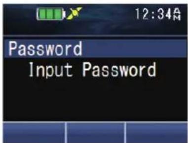
■ Transceiver Password
If the transceiver is password protected, "Input Password" will appear on the display when the power is turned on. To unlock the transceiver, enter the correct password.
1 Press the key programmed as [Transceiver Password] to enter Transceiver Password Mode.
Alternatively, press the key programmed as [Menu] to enter Transceiver Password Mode using the Menu Mode.
- If a password has been registered and the [Transceiver Password] function has not been programmed to a key or configured to the menu, the transceiver enters Transceiver Password Mode when the power is turned on.
2 Enter a number using the [▲] and [▼] keys.
- On full key model transceivers, you can enter the password directly by pressing the keypad.
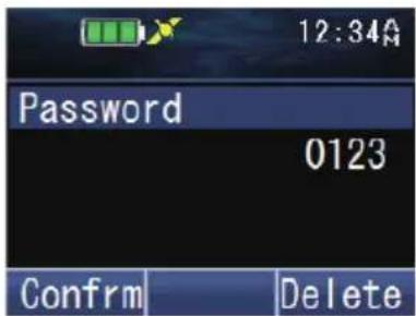
3 Press the [flor[] key to accept the number.
4 Repeat steps 2 and 3 to enter the entire password.
- Press the [→] or [#] key to delete an incorrectly entered number. Press and hold the [→] or [#] key to delete all numbers.
5 Press the [☐] or [♦key to confirm the entry.
- If you enter an incorrect password, an error tone sounds and the transceiver remains locked.
• The password can contain a maximum of 6 digits.
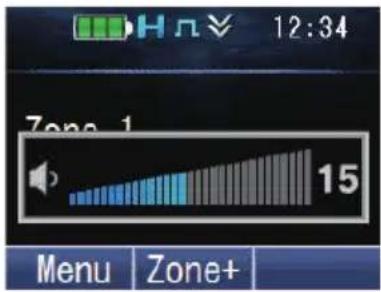
ADJUSTING THE VOLUME
Rotate the Power switch/ Volume control to adjust the volume.
Rotate clockwise to increase the volume and counterclockwise to decrease the volume.
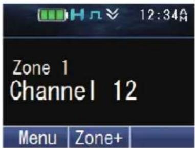
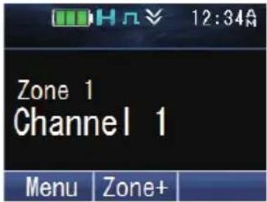
SELECTING A ZONE AND CHANNEL
1 Select the desired zone using the keys programmed as [Zone Up]/ [Zone Down]. Each zone contains a group of channels.
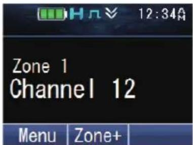
2 Select the desired channel using the keys programmed as [Channel Up]/[Channel Down]. Each channel is programmed with settings for transmitting and receiving.
- The transceiver may have names programmed for zones and channels. The zone name and channel name can contain up to 16 and 14 characters respectively.
TRANSMITTING
1 Select the desired zone and channel using the keys programmed as [Zone Up]/[Zone Down] and [Channel Up]/[Channel Down].
2 Press the PTT switch and speak into the microphone. Release the PTT switch to receive.
- The LED indicator lights red while transmitting and green while receiving a signal. This indicator can also be disabled by your dealer.
- For best sound quality at the receiving station, hold the microphone approximately 1.5 inches (3 cm to 4 cm) from your mouth.
■ Making Group Calls (P25 Conventional)
You can select a Talkgroup ID from the list to make a call to those parties on a Conventional channel.
1 Press the key programmed as [Group], [Group + Short Message] or [Group + Status] to enter Talkgroup ID Select Mode.
Alternatively, press the key programmed as [Menu] to enter Talkgroup ID Select Mode using the Menu Mode.
• The Talkgroup ID List appears on the display.
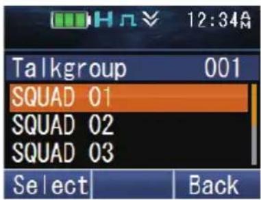
2 Press the [▲] and [▼] keys to select a Talkgroup ID/ name from the list that has been pre-entered into your transceiver.
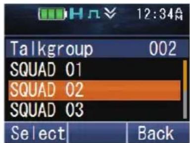
3 Press the [☐] or [★key to confirm the Talkgroup ID.
4 Press and hold the PTT switch to make the call.
- Speak into the transceiver as you would during a normal call.
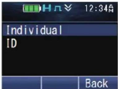
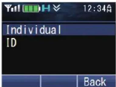
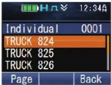
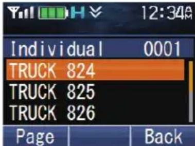
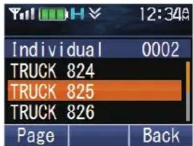
■ Making Individual Calls (P25 Conventional)
You can make calls to specific persons on a Conventional channel.
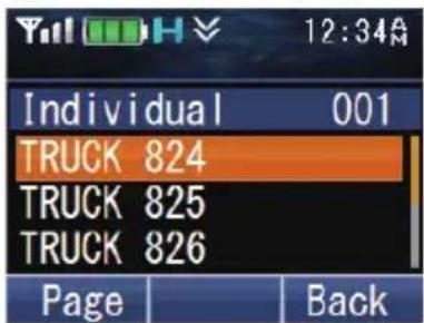
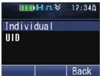
1 Press the key programmed as [Individual], [Individual + Short Message] or [Individual + Status] to enter Individual Call Mode.
Alternatively, press the key programmed as [Menu] to enter Individual Call Mode using the Menu Mode.
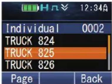
• The Individual ID List appears on the display.
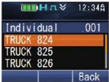
2 Press the [▲] and [▼] keys to select a unit ID from the list that has been pre-entered into your transceiver.
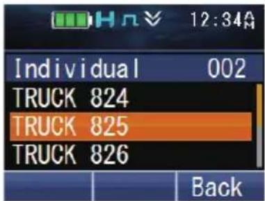
Alternatively, on full key models, you can enter a unit ID directly by pressing the keypad.
- Press the [ ]key to enter the manual input mode. To delete the code entered, press the [ ]key to delete one digit, or press and hold the [ ]key to delete all digits.
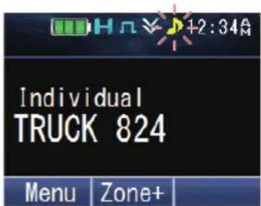
3 Press and hold the PTT switch to make the call.
- The “” icon blinks. “Individual” and the ID name of the target transceiver are displayed.
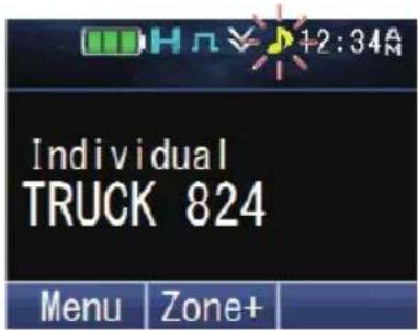
- Speak into the transceiver as you would during a normal call.
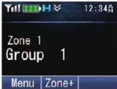
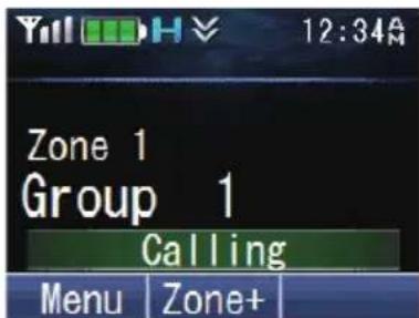
■ Making Group Calls (P25 Trunking)
You can select a channel with the Talkgroup ID you wanted to call to make a call to those parties on a Trunking channel.
- If the traffic channel is busy, a busy message appears and the busy tone sounds. Release the PTT switch and wait for the channel to become free. When the traffic channel becomes free, a proceed tone sounds.
1 Select the configured Talkgroup channel using the keys programmed as [Channel Up]/ [Channel Down].
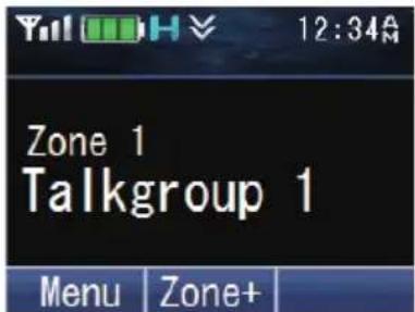
2 Press and hold the PTT switch to make the call.
- "Calling" appears on the display while the call is being made, and disappears once the call is established.
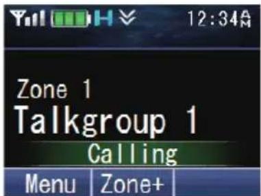
- Speak into the transceiver as you would during a normal call.
■ Making Individual Calls (P25 Trunking)
You can make calls to specific persons on a Trunking channel.
1 Press the key programmed as [Individual], [Individual + Short Message] or [Individual + Status] to enter Individual Call Mode.
Alternatively, press the key programmed as [Menu] to enter Individual Call Mode using the Menu Mode.
2 Press the [▲] and [▼] keys to select a unit ID from the list that has been pre-entered into your transceiver.
• The target unit ID/ name appears on the display.
Alternatively, on full key models, you can enter a unit ID directly by pressing the keypad.
- Press the [O] key to enter the manual input mode.
To delete the code entered, press the [→] key to delete one digit, or press and hold the [→] key to delete all digits.
3 Press and hold the PTT switch to make the call.
- The called ID and "Calling" appear on the display. "Calling" disappears once the call is established.
- Speak into the transceiver as you would during a normal call.
4 To end the call, press the key programmed as [Clear].
• The LCD display will return to the zone and channel screen after call ends.
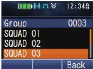
■ Making Group Calls (NXDN Conventional/ DMR Conventional)
You can select a group ID from the list to make a call to those parties on a Conventional channel.
1 Press the key programmed as [Group], [Group + Short Message] or [Group + Status] to enter Group Call Mode.
Alternatively, press the key programmed as [Menu] to enter Group Call Mode using the Menu Mode.
• The group ID list appears on the display.
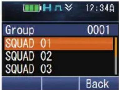
2 Press the [▲] and [▼] keys to select a Group ID/ name from the list that has been pre-entered into your transceiver.
3 Press and hold the PTT switch to make the call.
- The “ ” icon blinks. “Group” and the Group name of the target transceiver are displayed.
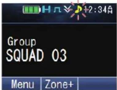
- Speak into the transceiver as you would during a normal call.
■ Making Individual Calls (NXDN Conventional/ DMR Conventional)
You can make calls to specific persons.
1 Press the key programmed as [Individual], [Individual + Short Message] or [Individual + Status] to enter Individual Call Mode.
Alternatively, press the key programmed as [Menu] to enter Individual Call Mode using the Menu Mode.
• The ID list appears on the display.
2 Press the [▲] and [▼] keys to select a unit ID from the list that has been pre-entered into your transceiver.
Alternatively, on full key models, you can enter a unit ID directly by pressing the keypad.
- Press the [ ] key to enter the manual input mode. To delete the code entered, press the [ ] key to delete one digit, or press and hold the [ ] key to delete all digits.
3 Press and hold the PTT switch to make the call.
- The “” icon blinks. “Individual” and the ID name of the target transceiver are displayed.
- Speak into the transceiver as you would during a normal call.
■ Making Group Calls (NXDN Trunking)
You can select a channel with the Group ID you wanted to call to make a call to those parties on a Trunking channel.
- If the traffic channel is busy, a busy message appears and the busy tone sounds. Release the PTT switch and wait for the channel to become free. When the traffic channel becomes free, a proceed tone sounds.
1 Select the configured Group channel using the keys programmed as [Channel Up]/ [Channel Down].
2 Press and hold the PTT switch to make the call.
- "Calling" appears on the display while the call is being made, and disappears once the call is established.
- Speak into the transceiver as you would during a normal call.
■ Making Individual Calls (NXDN Trunking)
You can make calls to specific persons on a Trunking channel.
1 Press the key programmed as [Individual], [Individual + Short Message] or [Individual + Status] to enter Individual Call Mode.
Alternatively, press the key programmed as [Menu] to enter Individual Call Mode using the Menu Mode.
• The ID list appears on the display.
2 Press the [▲] and [▼] keys to select a unit ID from the list that has been pre-entered into your transceiver.
Alternatively, on full key models, you can enter a unit ID directly by pressing the keypad.
- Press the [ ]key to enter the manual input mode. To delete the code entered, press the [ ]key to delete one digit, or press and hold the [ ]key to delete all digits.

3 Press and hold the PTT switch to make the call.
- "Individual" and the ID name of the target transceiver are displayed. "Calling" appears on the display while the call is being made, and disappears once the call is established.
- Speak into the transceiver as you would during a normal call.
RECEIVING
1 Select the desired zone and channel using the Selector knob and the [Zone Up]/[Zone Down] or [Channel Up]/[Channel Down] keys. (If the Scan function has been programmed, you can switch it on or off as desired.)
2 When you hear the caller's voice, readjust the volume as necessary.
- If signaling has been programmed on the selected channel, you will hear a call only if the signal tone matches the tone set up on your transceiver.
Note:
- Signaling allows your transceiver to code your calls. This will prevent you from listening to unwanted calls. It does not make calls private, it only prevents them from being heard by transceivers set with a different signaling code. Refer to “SIGNALING” {p. 46} for details.
- A ringing tone will sound when receiving a call if the alert tone has been enabled in the Alert Tone setting. For details, consult your dealer.
■ Receiving Group Calls (P25)
When you receive a group call on a Conventional channel and the received group ID matches the ID set up on your transceiver, you can hear the caller's voice.
When you receive a group call on a Trunking channel, the transceiver automatically switches to the traffic channel to receive the call.
■ Receiving Individual Calls (P25)
When you receive an individual call on a Conventional channel, a ringing tone will sound and the display will show the caller's ID. To respond to the call, press and hold the PTT switch and speak into the transceiver as you would during a normal call.
When you receive an individual call on a Trunking channel, a ringing tone will sound and the caller's ID appears on the display. To receive the call, press the PTT switch. To deny the call, press the key programmed as [Clear]. After receiving the call, you can respond to the call by pressing and holding the PTT switch and speaking into the transceiver as you would during a normal call. After the call is finished, press the key programmed as [Clear] to end the call.
■ Receiving Group Calls (NXDN)
When you receive a group call on a Conventional channel and the received group ID matches the ID set up on your transceiver, you can hear the caller's voice.
When on a Trunking channel, if the Group ID of a received call matches your Group ID, you will hear the call.
■ Receiving Individual Calls (NXDN)
When you receive an individual call on a Conventional channel, a ringing tone will sound and the display will show the caller's ID. To respond to the call, press and hold the PTT switch and speak into the transceiver as you would during a normal call.
When you receive an individual call on a Trunking channel, a ringing tone will sound and the caller's ID and “Individual” appear on the display. After receiving the call, you can respond to the call by pressing and holding the PTT switch and speaking into the transceiver as you would during a normal call.
■ Receiving Group Calls (DMR)
When you receive a group call on a Conventional channel and the received group ID matches the ID set up on your transceiver, you can hear the caller's voice.
■ Receiving Individual Calls (DMR)
When you receive an individual call on a Conventional channel, a ringing tone will sound and the display will show the caller's ID. To respond to the call, press and hold the PTT switch and speak into the transceiver as you would during a normal call.
PROGRAMMABLE FUNCTIONS
Refer to the tables in this section to determine which functions are available for appropriate channels. Function descriptions start on page 25. Please contact your dealer for further details on these functions.
MENU MODE
Many functions on this transceiver are selected or configured through the Menu instead of physical controls. Once you become familiar with the Menu system, you will appreciate the versatility it offers.
Some transceiver keys may already be programmed with functions listed in the Menu. Those functions can be accessed directly by pressing the key. All other functions can still be accessed using the transceiver Menu. Refer to “FUNCTION LIST” {p. 15} for the available Menu items.
MENU ACCESS
1 Press the key programmed as [Menu].
• The category list is shown.
- When there is only one category, the function list is shown (proceed to step 4).
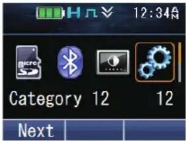
2 Press [▲]/[▼]/[◀]/[▶] to select a category item.
• On full key models, you can enter a category number directly.
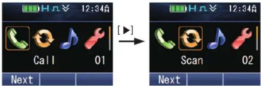
3 Press the [☐] or [★key to view the function list.
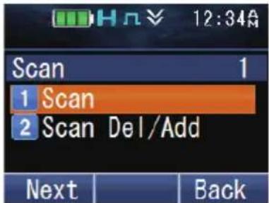
4 Press [▲]/[▼] to select a function item.
- On full key models, you can enter a function number directly.
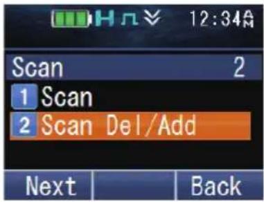
5 Press the [∅or [ ] key to set up the selected function item.
- Press the [for [#] key to return to the category list.
6 Press [▲]/[▼] to select your desired setting.
- For settings with more than one level, repeat steps 5 and 6.
7 Press the [☐] or [*key to set the selected setting and exit Menu mode.
- Press the [#or [#] key at any time to return to the previous display.
- Press the [ ]key at any time to exit Menu mode.
KEY MODE
Your transceiver operations vary according to the functions that your dealer has programmed onto the transceiver keys. Refer to “FUNCTION LIST” {p. 15} for the available programmable functions.
FUNCTION LIST
PF Key: Functions that can be programmed to the transceiver keys
Menu: Functions that can be accessed using the transceiver Menu
Analog Conv.: Channels set up for Analog Conventional Operation
NXDN Conv.: Channels set up for NXDN Conventional Operation
P25 Conv.: Channels set up for P25 Conventional Operation
DMR Conv.: Channels set up for DMR Conventional Operation
LTR Trunking: Channels set up for LTR Trunking Operation
NXDN Trunking: Channels set up for NXDN Trunking Operation
P25 Trunking: Channels set up for P25 Trunking Operation
√: Available
N/A: Not Available
■ Conventional Operation
| Function | Menu Display | PF Key | Menu | Analog Conv. | NXDN Conv. | P25 Conv. | DMR Conv. |
| None - | √ | N/A | √ | √ √ | √ | ||
| 2-tone 2-tone | √ | √ √ | √ √ | N/A | |||
| Activity Detection Activity Det | √ | √ √ | √ √ | √ √ | |||
| Activity Reset - | √ | N/A | √ | √ √ | √ | ||
| ANR Preset ANR Preset N/A | √ | √ √ | √ √ | √ | |||
| Audio Profile Audio Profile N/A | √ | √ √ | √ √ | √ | |||
| Function Menu Display | PF Key | Menu | Analog Conv. | NXDN Conv. | P25 Conv. | DMR Conv. | |
| Auto Telephone Auto Telephone | √ | √ | N/A | N/A N/A | N/A | ||
| Autodial Auto Dial | √ | √ √ | √ | N/A | N/A | ||
| Autodial Programming Auto Dial | Prog | √ | √ √ | √ | √ √ | ||
| AUX AUX | √ | √ √ | √ | √ √ | |||
| Backlight - | √ | N/A | √ | √ √ | √ | ||
| Battery Information Battery Info | N/A | √ | √ √ | √ √ | |||
| Battery Status Battery Status | √ | √ √ | √ | √ √ | |||
| Bluetooth Bluetooth | √ | √ √ | √ | √ √ | |||
| Bluetooth Connect/ Disconnect - | √ | N/A | √ | √ √ | √ | ||
| Bluetooth Device BT Device N/A | √ | √ √ | √ √ | ||||
| Bluetooth Discoverable Discoverable | N/A | √ | √ √ | √ √ | |||
| Bluetooth Headset Connection Type | BT Headset Typ | N/A | √ | √ √ | √ √ | ||
| Bluetooth Information | Bluetooth Info | N/A | √ | √ √ | √ √ | ||
| Bluetooth Speaker | BT Speaker | √ | √ √ | √ | √ √ | ||
| Broadcast | Broadcast | √ | √ | N/A | N/A N/A | √ | |
| Call 1 ~ 6 | - | √ | N/A | √ | √ √ | √ | |
| Call Interruption | - | √ | N/A | N/A N/A | N/A | √ | |
| Call Response | - | √ | N/A | √ | √ | N/A | N/A |
| Channel Down | - | √ | N/A | √ | √ √ | √ | |
| Channel Entry | - | √ | N/A | √ | √ √ | √ | |
| Channel Information | - | √ | N/A | √ | √ | N/A | N/A |
| Channel Recall | - | √ | N/A | √ | √ √ | √ | |
| Channel Select *1 | - | √ | N/A | √ | √ √ | √ | |
| Channel Up | - | √ | N/A | √ | √ √ | √ | |
| Clear | - | √ | N/A | √ | √ √ | √ | |
| Clock | Clock | √ | √ √ | √ | √ √ | ||
| Clock Adjustment | Clock Adjust | √ | √ √ | √ | √ √ | ||
| Color Scheme | Color Scheme | N/A | √ | √ √ | √ √ | ||
| CW Message | - | √ | N/A | N/A | √ | N/A | N/A |
| Digit 10x Down *2 | - | √ | N/A | √ | N/A | N/A | N/A |
| Digit 10x Up *2 | - | √ | N/A | √ | N/A | N/A | N/A |
| Digit 1x Down *2 | - | √ | N/A | √ | N/A | N/A | N/A |
| Digit 1x Up *2 | - | √ | N/A | √ | N/A | N/A | N/A |
| Direct Channel 1 ~ 5 | - | √ | N/A | √ | √ √ | √ | |
| Direct Channel 1 ~ 5 Select | Direct Ch 1 Sel ~ Direct Ch 5 Sel | √ | √ √ | √ | √ √ | ||
| Display Format | Display Format | √ | √ √ | √ | √ √ | ||
| Eject SD Card | Eject Card | √ | √ √ | √ | √ √ | ||
| Emergency *3 | - | √ | N/A | √ | √ √ | √ | |
| External Mic Sense Ext Mic Sense N/A | √ | √ √ | √ √ | √ | |||
| External Speaker External SP | √ | √ √ | √ √ | √ √ | |||
| Fixed Volume Fixed Volume | √ | √ √ | √ √ | √ √ | |||
| Format SD Card Format Card | √ | √ √ | √ √ | √ √ | |||
| Front Panel Programming Panel Program | √ | √ √ | √ √ | √ √ | |||
| Function - | √ | N/A | √ | √ √ | √ | ||
| GPS GPS | √ | √ √ | √ √ | √ √ | |||
| GPS/ Bluetooth Reset GPS/BT Reset N/A | √ | √ √ | √ √ | √ | |||
| GPS Position Display GPS Pos Disp | √ | √ √ | √ √ | √ √ | |||
| Group *4 | Group | √ | √ √ | √ √ | √ √ | ||
| Group + Short Message *4 | Group+SDM | √ | √ √ | √ √ | √ √ | ||
| Group + Status *4 | Group+Status | √ | √ √ | √ √ | √ √ | ||
| Group ID/ Channel Entry - | √ | N/A | √ | √ √ | √ | ||
| High Transmit Power High TX Power | √ | √ √ | √ √ | √ √ | |||
| Home Channel - | √ | N/A | √ | √ √ | √ | ||
| Home Channel Select Home Ch Sel | √ | √ √ | √ √ | √ √ | |||
| Individual *4 | Individual | √ | √ √ | √ √ | √ √ | ||
| Individual + Short Message *4 | Indiv+SDM | √ | √ √ | √ √ | √ √ | ||
| Individual + Status *4 | Indiv+Status | √ | √ √ | √ √ | √ √ | ||
| IP Address | IP Address | N/A | √ | N/A | N/A | N/A | N/A |
| Key Delete | Key Delete | √ | √ √ | √ √ | √ √ | ||
| Key Lock | - | √ | N/A | √ | √ √ | √ | |
| Keyset *5 | Keyset | √ | √ | N/A | N/A | √ | N/A |
| Language | Language | N/A | √ | √ √ | √ √ | ||
| LCD Brightness | LCD Brightness | √ | √ √ | √ √ | √ √ | ||
| Lone Worker | Lone Worker | √ | √ √ | √ √ | √ √ | ||
| Low Transmit Power | Low TX Power | √ | √ √ | √ √ | √ √ | ||
| Maintenance | Maintenance | √ | √ √ | √ √ | √ √ | ||
| Manual Site Hunt Manual Hunt | √ | √ | N/A | N/A | N/A | √ | |
| Medium Transmit Power | Med TX Power | N/A | √ | √ √ | √ √ | ||
| Menu | - | √ | N/A | √ | √ √ | √ | |
| Mic Sense | Mic Sense | N/A | √ | √ √ | √ √ | ||
| Microphone Type | Mic Type | N/A | √ | √ √ | √ √ | ||
| Monitor | Monitor | √ | √ √ | √ √ | √ √ | ||
| Monitor Momentary | - | √ | N/A | √ | √ √ | √ | |
| Operator Selectable Tone | OST | √ | √ √ | N/A | N/A | N/A | |
| OST Down | - | √ | N/A | √ | N/A | N/A | N/A |
| OST List OST List | √ | √ √ | N/A N/A | N/A N/A | |||
| OST Up - | √ | N/A | √ | N/A N/A | N/A N/A | ||
| OVCM OVCM | √ | √ | N/A N/A | N/A N/A | √ | ||
| Playback Playback | √ | √ √ | √ √ | √ √ | |||
| Playback (Last Recording) - | √ | N/A | √ | √ √ | √ | ||
| Priority-channel Select Pri Ch Select | √ | √ √ | √ √ | √ √ | |||
| Radio Check Radio Check N/A | √ | √ | N/A N/A | N/A N/A | |||
| Radio Inhibit Inhibit N/A | √ | √ | N/A N/A | N/A N/A | |||
| Radio Uninhibit Uninhibit N/A | √ | √ | N/A N/A | N/A N/A | |||
| Receive Entry *2 | Receive Entry | √ | √ √ | N/A N/A | N/A N/A | ||
| Regroup Request Regroup Req | √ | √ | N/A N/A | N/A N/A | N/A N/A | ||
| Rekey Request *5 | Rekey Request | √ | √ | N/A N/A | N/A | √ | N/A |
| Remote Control | Remote Control | √ | √ | N/A | √ | N/A | √ |
| RX Audio Equalizer (High) | RX EQ High | N/A | √ | √ √ | √ √ | ||
| RX Audio Equalizer (High Midrange) | RX EQ High Mid | N/A | √ | √ √ | √ √ | ||
| RX Audio Equalizer (Midrange) | RX EQ Midrange | N/A | √ | √ √ | √ √ | ||
| RX Audio Equalizer (Low Midrange) | RX EQ Low Mid N/A | √ | √ √ | √ √ | |||
| RX Audio Equalizer (Low) | RX EQ Low | N/A | √ | √ √ | √ √ | ||
| RX Auto Gain Control | RX AGC | N/A | √ | √ √ | √ √ | ||
| Save GPS Data | Save GPS Data | √ | √ √ | √ √ | √ √ | ||
| Save Log Data | Save Log Data | √ | √ √ | √ √ | √ √ | ||
| Scan | Scan | √ | √ √ | √ √ | √ √ | ||
| Scan Delete/ Add | Scan Del/Add | √ | √ √ | √ √ | √ √ | ||
| Scan Normal | Scan Normal | √ | √ √ | √ √ | √ √ | ||
| Scan Program | Scan Program | √ | √ √ | √ √ | √ √ | ||
| Scrambler/ Encryption | Scram/Encryp | √ | √ √ | √ √ | √ √ | ||
| Scrambler/ Encryption Code | Scram/Enc Code | √ | √ √ | √ √ | √ √ | ||
| Send the GPS Data | Send GPS Data | √ | √ √ | √ √ | √ √ | ||
| Short Message | Short Message | √ | √ √ | √ | N/A | √ | |
| Site Down | - | √ | N/A N/A N/A N/A N/A | ||||
| Site Lock | Site Lock | √ | √ | N/A N/A N/A N/A | |||
| Site Number Site No. | N/A | √ | N/A N/A N/A N/A | ||||
| Site Select *1 | Site | √ | √ | N/A N/A N/A N/A | |||
| Site Up | - | √ | N/A N/A N/A N/A | ||||
| Speaker Attenuation | - | √ | N/A | √ | √ √ | √ | |
| Function Menu Display | PF Key | Menu | Analog Conv. | NXDN Conv. | P25 Conv. | DMR Conv. |
| Speaker Type Speaker Type N/A | √ | √ √ | √ | √ | ||
| Squelch Level Squelch Level | √ √ √ | N/A | N/A N/A | |||
| Squelch Off Squelch Off | √ √ √ | √ √ | √ √ | |||
| Squelch Off Momentary - | √ N/A | √ | √ √ | √ | ||
| Stack Stack | √ √ √ | √ √ | √ √ | |||
| Status Status | √ √ √ | √ | N/A | √ | ||
| Surveillance Surveillance | √ √ √ | √ √ | √ √ | |||
| System Down - | √ N/A | N/A N/A | N/A N/A | N/A | ||
| System Lock System Lock | √ √ | N/A | N/A N/A | N/A | ||
| System Search System Search | √ √ | N/A | N/A N/A | N/A | ||
| System Select *1 | System | √ √ | N/A | N/A N/A | N/A | |
| System Up - | √ N/A | N/A N/A | N/A N/A | N/A | ||
| Tactical Zone - | √ N/A | √ | N/A | √ | N/A | |
| Talk Around | Talk Around | √ √ √ | √ √ √ | |||
| Talkgroup Reset | Talkgroup Rst | √ √ | N/A | N/A | √ | N/A |
| Task Request Confirmation | Task | √ √ | N/A | √ | N/A | √ |
| Telephone Disconnect | - | √ N/A | N/A N/A | N/A N/A | N/A | |
| Transceiver Password | Password | √ √ √ | √ √ √ | |||
| TX Audio Equalizer (High) | TX EQ High | N/A | √ √ √ | √ √ | ||
| TX Audio Equalizer (High Midrange) | TX EQ High Mid | N/A | √ √ √ | √ √ | ||
| TX Audio Equalizer (Midrange) | TX EQ Midrange | N/A | √ √ √ | √ √ | ||
| TX Audio Equalizer (Low Midrange) | TX EQ Low Mid | N/A | √ √ √ | √ √ | ||
| TX Audio Equalizer (Low) | TX EQ Low | N/A | √ √ √ | √ √ | ||
| TX Auto Gain Control | TX AGC | N/A | √ √ √ | √ √ | ||
| Vibrator | Vibrator | √ √ √ | √ √ √ | |||
| Voice Memo | Voice Memo | √ √ √ | √ √ √ | |||
| VOX | VOX Level | √ √ √ | √ √ √ | |||
| VOX Function VOX | √ √ √ | √ √ √ | ||||
| Zeroize | Zeroize | √ √ √ | √ √ √ | |||
| Zone Delete/ Add | Zone Del/ Add | √ √ √ | √ √ √ | |||
| Zone Down | - | √ N/A | √ √ √ | √ | ||
| Zone Select *6 | - | √ N/A | √ √ √ | √ | ||
| Zone Up | - | √ N/A | √ √ √ | √ |
Trunking Operation
| Function Menu Display | PF Key | Menu | LTR Trunking | NXDN Trunking | P25 Trunking |
| None - | √ | N/A | √ | √ | |
| 2-tone 2-tone | √ | √ | N/A | √ | |
| Activity Detection Activity Det | √ | √ | √ | ||
| Activity Reset - | √ | N/A | √ | √ | |
| ANR Preset ANR Preset N/A | √ | √ | √ | ||
| Audio Profile Audio Profile N/A | √ | √ | √ | ||
| Auto Telephone Auto Telephone | √ | √ | N/A N/A | ||
| Autodial Auto Dial | √ | √ | √ | ||
| Autodial Programming Auto Dial Prog | √ | √ | √ | ||
| AUX AUX | √ | √ | √ | ||
| Backlight - | √ | N/A | √ | √ | |
| Battery Information | Battery Info | N/A | √ | √ | √ |
| Battery Status | Battery Status | √ | √ | √ | |
| Bluetooth | Bluetooth | √ | √ | √ | |
| Bluetooth Connect/ Disconnect | - | √ | N/A | √ | √ |
| Bluetooth Device | BT Device | N/A | √ | √ | √ |
| Bluetooth Discoverable | Discoverable | N/A | √ | √ | √ |
| Bluetooth Headset Connection Type | BT Headset Typ | N/A | √ | √ | √ |
| Bluetooth Information | Bluetooth Info | N/A | √ | √ | √ |
| Bluetooth Speaker | BT Speaker | √ | √ | √ | |
| Broadcast | Broadcast | √ | √ | N/A | √ |
| Call 1 ~ 6 | - | √ | N/A | √ | √ |
| Call Interruption | - | √ | N/A N/A | N/A N/A | |
| Call Response | - | √ | N/A N/A | √ | |
| Channel Down | - | √ | N/A | √ | √ |
| Channel Entry | - | √ | N/A | √ | √ |
| Channel Information | - | √ | N/A N/A | N/A N/A | |
| Channel Recall | - | √ | N/A | √ | √ |
| Channel Select *1 | - | √ | N/A | √ | √ |
| Channel Up | - | √ | N/A | √ | √ |
| Clear - | √ | N/A | √ | √ | |
| Clock | Clock | √ | √ | √ | |
| Clock Adjustment | Clock Adjust | √ | √ | √ | |
| Color Scheme | Color Scheme | N/A | √ | √ | √ |
| CW Message - | √ | N/A N/A | N/A N/A | ||
| Digit 10x Down *2 | - | √ | N/A N/A | N/A N/A | |
| Digit 10x Up *2 | - | √ | N/A N/A N/A | N/A | |
| Digit 1x Down *2 | - | √ | N/A N/A N/A | N/A | |
| Digit 1x Up *2 | - | √ | N/A N/A N/A | N/A | |
| Direct Channel 1 ~ 5 - | √ | N/A | √ | √ | |
| Direct Channel 1 ~ 5 Select | Direct Ch 1 Sel ~ Direct Ch 5 Sel | √ | √ | √ | |
| Display Format Display Format | √ | √ | √ | ||
| Eject SD Card Eject Card | √ | √ | √ | ||
| Emergency *3 | - | √ | N/A | √ | √ |
| External Mic Sense Ext Mic Sense | N/A | √ | √ | √ | |
| External Speaker External SP | √ | √ | √ | ||
| Fixed Volume Fixed Volume | √ | √ | √ | ||
| Format SD Card Format Card | √ | √ | √ | ||
| Front Panel Programming Panel Program | √ | √ | N/A N/A N/A | ||
| Function - | √ | N/A | √ | √ | |
| GPS GPS | √ | √ | √ | ||
| GPS/ Bluetooth Reset GPS/BT Reset | N/A | √ | √ | √ | |
| GPS Position Display | GPS Pos Disp | √ | √ | √ | |
| Group *4 | Group | √ | √ | √ | |
| Group + Short Message *4 | Group+SDM | √ | √ | √ | |
| Group + Status *4 | Group+Status | √ | √ | √ | |
| Group ID/ Channel Entry | - | √ | N/A | √ | √ |
| High Transmit Power | High TX Power | √ | √ | √ | |
| Home Channel | - | √ | N/A | √ | √ |
| Home Channel Select Home Ch Sel | √ | √ | √ | ||
| Individual *4 | Individual | √ | √ | √ | |
| Individual + Short Message *4 | Indiv+SDM | √ | √ | √ | |
| Individual + Status *4 | Indiv+Status | √ | √ | √ | |
| IP Address | IP Address | N/A | √ | N/A N/A | √ |
| Key Delete | Key Delete | √ | √ | √ | |
| Key Lock | - | √ | N/A | √ | √ |
| Keyset *5 | Keyset | √ | √ | N/A N/A | √ |
| Language | Language | N/A | √ | √ | √ |
| LCD Brightness | LCD Brightness | √ | √ | √ | |
| Lone Worker | Lone Worker | √ | √ | √ | |
| Low Transmit Power Low TX Power | √ | √ | √ | ||
| Maintenance | Maintenance | √ | √ | √ |
| Function Menu Display | PF Key | Menu | LTR Trunking | NXDN Trunking | P25 Trunking | |
| Manual Site Hunt Manual Hunt | √ | √ | N/A N | N/A N/A | ||
| Medium Transmit Power Med TX Power N/A | √ | √ √ | √ | |||
| Menu - | √ | N/A | √ | √ √ | ||
| Mic Sense Mic Sense N/A | √ | √ √ | √ | |||
| Microphone Type Mic Type N/A | √ | √ √ | √ | |||
| Monitor Monitor | √ | √ √ | √ √ | |||
| Monitor Momentary - | √ | N/A | √ | √ √ | ||
| Operator Selectable Tone OST | √ | √ | N/A N | N/A N/A | ||
| OST Down - | √ | N/A N | N/A N/A | N/A | ||
| OST List OST List | √ | √ | N/A N | N/A N/A | ||
| OST Up | - | √ | N/A N | N/A N/A | N/A | |
| OVCM | OVCM | √ | √ | N/A N | N/A N/A | |
| Playback | Playback | √ | √ √ | √ √ | ||
| Playback (Last Recording) | - | √ | N/A | √ | √ √ | |
| Priority-channel Select | Pri Ch Select | √ | √ √ | N/A | √ | |
| Radio Check | Radio Check | N/A | √ | √ | N/A N/A | |
| Radio Inhibit | Inhibit | N/A | √ | √ | N/A N/A | |
| Radio Uninhibit | Uninhibit | N/A | √ | √ | N/A N/A | |
| Receive Entry *2 | Receive Entry | √ | √ | N/A N | N/A N/A | |
| Regroup Request | Regroup Req | √ | √ | N/A N/A | √ | |
| Rekey Request *5 | Rekey Request | √ | √ | N/A N/A | √ | |
| Remote Control | Remote Control | √ | √ | N/A | √ | N/A |
| RX Audio Equalizer (High) | RX EQ High | N/A | √ | √ √ | √ | |
| RX Audio Equalizer (High Midrange) | RX EQ High Mid | N/A | √ | √ √ | √ | |
| RX Audio Equalizer (Midrange) | RX EQ Midrange | N/A | √ | √ √ | √ | |
| RX Audio Equalizer (Low Midrange) | RX EQ Low Mid | N/A | √ | √ √ | √ | |
| RX Audio Equalizer (Low) | RX EQ Low | N/A | √ | √ √ | √ | |
| RX Auto Gain Control | RX AGC N/A | √ | √ √ | √ | ||
| Save GPS Data | Save GPS Data | √ | √ √ | √ √ | ||
| Save Log Data | Save Log Data | √ | √ √ | √ √ | ||
| Scan | Scan | √ | √ √ | √ √ | ||
| Scan Delete/ Add Scan Del/Add | √ | √ √ | √ √ | |||
| Scan Normal | Scan Normal | √ | √ √ | √ √ | ||
| Scan Program | Scan Program | √ | √ √ | √ √ | ||
| Scrambler/ Encryption | Scram/Encryp | √ | √ √ | √ √ | ||
| Scrambler/ Encryption Code | Scram/Enc Code | √ | √ √ | √ √ |
| Function Menu Display | PF Key | Menu | LTR Trunking | NXDN Trunking | P25 Trunking |
| Send the GPS Data Send GPS Data | ✓ | ✓ ✓ | ✓ ✓ | ||
| Short Message Short Message | ✓ ✓ ✓ | ✓ | N/A | ||
| Site Down - | ✓ N/A N/A | ✓ | N/A | ||
| Site Lock Site Lock | ✓ ✓ | N/A | ✓ | ✓ | |
| Site Number Site No. N/A | ✓ N/A | ✓ | ✓ | ||
| Site Select ^*1 | Site | ✓ ✓ | N/A | ✓ | N/A |
| Site Up - | ✓ N/A N/A | ✓ | N/A | ||
| Speaker Attenuation - | ✓ N/A | ✓ ✓ | ✓ | ||
| Speaker Type Speaker Type N/A | ✓ ✓ ✓ | ✓ | |||
| Squelch Level Squelch Level | ✓ ✓ | N/A N/A N/A | |||
| Squelch Off Squelch Off | ✓ ✓ ✓ | ✓ ✓ | |||
| Squelch Off Momentary - | ✓ N/A | ✓ ✓ ✓ | |||
| Stack | Stack | ✓ ✓ ✓ | ✓ ✓ | ||
| Status | Status | ✓ ✓ ✓ | ✓ ✓ | ||
| Surveillance | Surveillance | ✓ ✓ ✓ | ✓ ✓ | ||
| System Down | - | ✓ N/A N/A | ✓ | N/A | |
| System Lock | System Lock | ✓ ✓ | N/A | ✓ | N/A |
| System Search | System Search | ✓ ✓ | N/A | ✓ | ✓ |
| System Select ^*1 | System | ✓ ✓ | N/A | ✓ | N/A |
| System Up | - | ✓ N/A N/A | ✓ | N/A | |
| Tactical Zone | - | ✓ N/A N/A N/A | N/A | ||
| Talk Around | Talk Around | ✓ ✓ ✓ | N/A N/A | ||
| Talkgroup Reset | Talkgroup Rst | ✓ ✓ | N/A N/A N/A | ||
| Task Request Confirmation | Task | ✓ ✓ | N/A | ✓ | N/A |
| Telephone Disconnect | - | ✓ N/A | ✓ | N/A N/A | |
| Transceiver Password | Password | ✓ ✓ ✓ | ✓ ✓ | ||
| TX Audio Equalizer (High) | TX EQ High | N/A | ✓ ✓ ✓ | ✓ | |
| TX Audio Equalizer (High Midrange) | TX EQ High Mid | N/A | ✓ ✓ ✓ | ✓ | |
| TX Audio Equalizer (Midrange) | TX EQ Midrange | N/A | ✓ ✓ ✓ | ✓ | |
| TX Audio Equalizer (Low Midrange) | TX EQ Low Mid | N/A | ✓ ✓ ✓ | ✓ | |
| TX Audio Equalizer (Low) | TX EQ Low | N/A | ✓ ✓ ✓ | ✓ | |
| TX Auto Gain Control | TX AGC | N/A | ✓ ✓ ✓ | ✓ | |
| Vibrator | Vibrator | ✓ ✓ ✓ | ✓ ✓ | ||
| Voice Memo | Voice Memo | ✓ ✓ ✓ | ✓ ✓ | ||
| VOX | VOX Level | ✓ ✓ ✓ | ✓ ✓ | ||
| VOX Function VOX | ✓ ✓ ✓ | ✓ ✓ | |||
| Zeroize | Zeroize | ✓ ✓ ✓ | ✓ ✓ | ||
| Function Menu Display | PF Key | Menu | LTR Trunking | NXDN Trunking | P25 Trunking | |
| Zone Delete/ Add Zone Del/ Add | √ | √ √ | N/A N | N/A | ||
| Zone Down - | √ | N/A | √ | √ √ | ||
| Zone Select *6 | - | √ | N/A | √ | √ √ | |
| Zone Up - | √ | N/A | √ | √ √ |
*1 Channel Select, Site Select and System Select can be programmed only on the Selector knob.
*2 Available only for 5-tone calls.
*3 Emergency can be programmed only on the Auxiliary (orange) key and the optional speaker/microphone PF 1 (orange) key.
*4 Group, Group + Short Message, Group + Status, Individual, Individual + Short Message and Individual + Status function as Selcall in FleetSync systems and 5-tone Signaling.
*5 Keyset and Rekey Request can be used when set as P25 OTAR.
*6 Zone Select can be programmed only on the Selector knob and the Lever switch.
CHARACTER ENTRY
While in the character entry screen, you can use the following two methods to enter the characters:
■ Pressing the [▲]/[▼] keys
Press [▲]/[▼] to cycle the characters from A \~ Z, a \~ z, 0 \~ 9, and a space (default settings).
You can also assign a character to an optional key and later press that key to recall the assigned character: A \~ Z, a \~ z, 0 \~ 9, or a space and characters.
■ Using the keypad (Full key models only)
Press the keypad keys to enter characters as shown in the table below.
You can press the [O] or [*] key repeatedly to switch the input mode (upper case → lower case → numbers → back to beginning).
| Keypad Character Cycle (Upper Case) Character Cycle (Lower Case) | |
| 1 @ # " () ! _ @ # " () ! _ | |
| 2 A B C a b c | |
| 3 D E F d e f | |
| 4 G H | g h i | |
| 5 J K L j k l | |
| 6 M N O m n o | |
| 7 P Q R S p q r s | |
| 8 T U V t u v | |
| 9 W X Y Z w x y z | |
| 0 (space) . , ? / ' & (space) . , ? / ' & | |
FUNCTIONS OVERVIEW
Following is a brief overview of the functions available on the transceiver accessible using the Menu and/or programmable to the transceiver keys.
For details on functions that are not included in "FUNCTION DETAILS" {p. 37}, please contact your dealer.
- Texts in the < > brackets are the displays for the key guides.
None
No function has been programmed.
2-tone <2-tone>
Allows you to quickly call the 2-tone list that have been programmed onto your transceiver.
■ Activity Detection
Enables or disables Activity Detection. If an event occurs while Activity Detection is enabled, the transceiver enters Emergency mode.
■ Activity Reset
While Activity Detection is active, press this key to reset the Activity Detection countdown timer. This allows you to remain in a tilted or stationary position, etc., without activating the Emergency mode unnecessarily.
ANR Preset
Cancels the background noise to improve the audio quality during transmission.
Audio Profile
Allows you to select a preferred preset profile that suits the operating environment and operating condition of the transceiver.
■ Auto Telephone
Automatically searches and connects to a telephone repeater that can be connected in LTR Trunking system.
Autodial
Allows you to quickly call telephone numbers that have been programmed onto your transceiver. Refer to “Autodial” {p. 41}.
■ Autodial Programming
Allows you to edit the Autodial list.
AUX
Toggles the auxiliary port ON and OFF. When toggled on, the optional feature connected to the auxiliary port will be activated and the indicator will appear on the display.
Backlight
Press this key to turn the display backlight on or off. If Auto backlight is activated by your dealer, the backlight can be set to activate by key operations or when receiving a call/ message.
Battery Information
Allows you to check the detailed information of the Intelligent Battery installed on your transceiver. Refer to “BATTERY INFORMATION DISPLAY” {p. 50}.
Battery Status
Allows you to view the battery power status. Battery status is represented by the number of times the LED indicator flashes red. Four flashes represents full power, three represents medium power, two represents low power, and one represents very low power. If the LED flashes red only one time, recharge or replace your battery pack immediately. When the Low Battery Warning function is active {p. 59} and the battery power is low, this key will not operate.
If the Battery Level Tone has been enabled, a beep tone will sound according to the number of flashes from the LED.
Bluetooth
Enables or disables the Bluetooth function. Refer to “Bluetooth” {p. 62}.
Bluetooth Connect/ Disconnect
Press this key to pair with the selected Bluetooth device when a Bluetooth device is not connected. When a Bluetooth device is connected, press this key to disconnect the Bluetooth device.
Bluetooth Device
Activates Bluetooth Device mode.
Bluetooth Discoverable
Allows the transceiver to respond to the search for Bluetooth-enabled devices.
Bluetooth Headset Connection Type
Allows you to select the type of Bluetooth headset to be connected to the transceiver via HSP connection.
Bluetooth Information
Allows you to display the Bluetooth device name of the transceiver.
Bluetooth Speaker
Allows you to switch the speaker from the transceiver's built-in speaker to the speaker of a connected Bluetooth device.
Broadcast
Allows you to make a Broadcast Group Call. Switches between Broadcast Group Call and Conference Group Call when Broadcast Group Call is enabled.
■ Call 1 \~ 6
Press this key to send a message or initiate a call.
- Call Interruption
Allows a transceiver other than the transmitting transceiver to terminate voice communications by sending and receiving a Call Interruption request message. If a transceiver receives a Call Interruption request message on the channel where the transceiver is performing voice communications, the transceiver terminates the voice communications.
- Call Response
Press this key to respond to an Individual Call. When an Individual Call is received, the Alert tone stops.
Channel Down
Press this key to decrease the channel number. {p. 4}
■ Channel Entry
Press this key to enter Channel Entry Mode, to select a channel.
■ Channel Information
Allows you to cycle through the display information as follows: Channel name > Zone-channel number > Frequency > QT/DQT > RAN
■ Channel Recall
Press this key during Scan to return to the last called zone and channel.
Channel Select
Turn the Selector knob clockwise to increase the channel number and counterclockwise to decrease it.
Channel Up
Press this key to increase the channel number. {p. 4}
Clear
Press this key to end a call or cancel a data transmission.
Clock
Refer to "CLOCK" {p. 48}.
■ Clock Adjustment
Allows you to set the clock. Refer to "CLOCK" {p. 48}.
Color Scheme
Allows you to change the color scheme of the LCD. Refer to “COLOR SCHEME” {p. 49}.
CW Message
Press this key to send the CW message.
- Digit 10x Down <10x->
Press this key to decrease the Selcall number by 10 with each press.
- Digit 10x Up <10x+>
Press this key to increase the Selcall number by 10 with each press.
Digit 1x Down <1x->
Press this key to decrease the Selcall number by 1 with each press.
Digit 1x Up <1x+>
Press this key to increase the Selcall number by 1 with each press.
■ Direct Channel 1 \~ 5
Press one of these keys to jump to a frequently used zone and channel (pre-programmed by your dealer). If activated by your dealer, you can set your own Direct Channels by selecting your desired zone and channel using Direct Channel 1 \~ 5 Select.
■ Direct Channel 1 \~ 5 Select
Allows you to set the currently selected zone and channel as the Direct Channel 1 \~ 5.
■ Display Format
Allows you to switch the display between the zone-channel number and the channel name.
■ Eject SD Card
Allows you to eject the microSD card.
Emergency
Refer to "EMERGENCY CALLS" {p. 43}.
External Mic Sense
Activates External Mic Sense mode.
■ External Speaker
Switches the speaker from the transceiver's built-in speaker to an optional external speaker.
■ Fixed Volume
Allows you to change the volume level of the tone.
■ Format SD Card
Allows you to format the microSD card.
■ Front Panel Programming
Activates Front Panel Programming mode. This mode allows you to change the frequency and other data of a Conventional channel and to add new Conventional channels using your transceiver even when the FPU (Field Programming Unit) software or a computer is not available.
Function
Press this key, then press a programmable key to activate its secondary function.
GPS
Enables or disables the GPS function.
GPS/ Bluetooth Reset
Activates GPS/ Bluetooth Reset mode.
■ GPS Position Display
Allows you to display your location data. Location data that is saved on the microSD card using the Save GPS Data function or in GPS Position Display mode can be displayed.
Group
Activates Group Call Mode.
■ Group + Short Message
Allows you to specify a Group ID to send short messages.
■ Group + Status
Allows you to specify a Group ID to send status messages.
■ Group ID/ Channel Entry
In NXDN Trunking systems, press this key to enter a Group ID. In other operating systems, this key functions the same as Channel Entry.
■ High Transmit Power
Turns High Transmit Power on or off. When using a channel programmed with low or medium power, this allows you to change the output power to high.
Home Channel
Press this key to jump to your home zone and channel (pre-programmed by your dealer). If activated by your dealer, you can set your own Home Channel by selecting your desired zone and channel using Home Channel Select.
Home Channel Select
Allows you to set the currently selected channel to Home Channel.
■ Individual
Refer to "Making Individual Calls" {p. 6} {p. 8}.
■ Individual + Short Message
Allows you to specify a Unit ID to send short messages.
■ Individual + Status
Allows you to specify a Unit ID to send status messages.
IP Address
Displays the IP address.
■ Key Delete
Allows you to delete the Encryption key. Refer to “DELETING THE ENCRYPTION KEY (AES (SCM*)/ DES (Built-in-DES or SCM*) and Enhanced Encryption only)” {p. 45}.
Key Lock
Press this key to lock the transceiver keys. Press the key again to unlock the keys. The Selector, Lever switch as well as the PTT key on an external microphone or a Bluetooth device still function normally, and the following functions can still be operated: Backlight, Battery Status, Call Response, Clear, Emergency, Function, Key Lock, LCD Brightness, Monitor, Monitor Momentary, Squelch Off, Squelch Off Momentary and Zeroize.
Keyset
Allows you to change the active Keyset stored in a Secure Cryptographic Module (SCM).
Language
Allows you to change the language of the text display on the LCD screen and the language of the voice announcement. Refer to “MULTI LANGUAGE” {p. 52}.
LCD Brightness
Allows you to adjust the brightness of the LCD backlight depending on the surrounding lighting conditions.
Lone Worker
Enables or disables Lone Worker function.
■ Low Transmit Power
Turns Low Transmit Power on or off. When using a channel programmed with medium or high power, this allows you to change the output power to low.
■ Maintenance
Allows you to display the signal strength, site information and Bit Error Rate (BER) on the LCD when constructing the system or during maintenance.
■ Manual Site Hunt
Enables or disables Manual Site Hunt function. Applicable to DMR Site Roaming only.
■ Medium Transmit Power
Turns Medium Transmit Power on or off. When using a channel programmed with low or high power, this allows you to change the output power to medium.
Menu
Press this key to select and perform functions using the transceiver Menu.
Mic Sense
Allows you to change the microphone sensitivity.
■ Microphone Type
Allows you to select a microphone type that suits the optional external microphone connected.
Monitor
Allows you to turn the transceiver signaling off, to listen to all calls that are received on the channel.
■ Monitor Momentary
Press and hold this key to momentarily turn the transceiver signaling off. Releasing this key turns the transceiver signaling back on. While signaling is off, you can listen to all calls that are received on the channel.
Operator Selectable Tone
Refer to "Operator Selectable Tone (OST)" {p. 46}.
■ OST Down
Press this key to decrease the Operator Selectable Tone number of your selected channel.
OST List
Allows you to enter OST List mode.
OST Up
Press this key to increase the Operator Selectable Tone number of your selected channel.
■ OVCM (Open Voice Channel Mode)
Allows the conversation of a received call to be heard even when the received ID does not match.
■ Playback
Refer to "Playback" {p. 78}.
■ Playback (Last Recording)
Refer to "Playback" {p. 78}.
■ Priority-channel Select
Allows you to set a channel as a priority channel.
Radio Check
Allows you to check whether the transceiver can be communicated or not.
Radio Inhibit
Allows you to inhibit the transceiver operation by remote control.
Radio Uninhibit
Allows you to uninhibit the transceiver operation by remote control.
Receive Entry
Press this key to change a 5-tone code by entering the code directly.
■ Regroup Request
Allows you to send a request to the dispatcher to join the talkgroup set up by the dispatcher. The channel name for the dynamic regroup channel appears on the display when the transceiver joins the talkgroup.
■ Rekey Request
Allows you to make a request to update the Encryption key.
■ Remote Control
Allows you to remotely control a specified transceiver from this transceiver.
In the NXDN and DMR systems, it allows you to operate the transceiver directly, send a remote control message and control the target transceiver.
RX Audio Equalizer (High)
Allows you to set the audio response for high frequencies.
■ RX Audio Equalizer (High Midrange)
Allows you to set the audio response for high midrange frequencies.
■ RX Audio Equalizer (Midrange)
Allows you to set the audio response for midrange frequencies.
■ RX Audio Equalizer (Low Midrange)
Allows you to set the audio response for low midrange frequencies.
■ RX Audio Equalizer (Low)
Allows you to set the audio response for low frequencies.
RX Auto Gain Control
Allows you to set the transceiver to automatically adjust the volume of the receiving sound to a specific level for easy listening.
■ Save GPS Data
Allows you to save the current date, time and location information on the microSD card.
■ Save Log Data
Allows you to save the operation and communication logs of this transceiver.
Scan
Refer to "SCAN" {p. 37}.
■ Scan Delete/ Add
Allows you to include or omit each channel in the scan sequence.
Scan Normal
Allows you to forcibly perform a non-priority scan even when priority scan has been set.
Scan Program
Allows you to reprogram the Scan List and Priority channels using your transceiver. Refer to "SCAN PROGRAMMING" {p. 38}.
■ Scrambler/ Encryption
Allows you to prevent a third party from listening in on your call. Refer to "SCRAMBLER (ANALOG/ LTR)/ ENCRYPTION (P25/ NXDN/ DMR)" {p. 44}.
■ Scrambler/ Encryption Code
Allows you to change the scrambler code used in the transmission. Refer to "SCRAMBLER (ANALOG/ LTR)/ ENCRYPTION (P25/ NXDN/ DMR)" {p. 44}.
Send the GPS Data
Allows you to send your positioning data to the base station when a GPS unit has been installed.
■ Short Message
Allows you to send short messages such as an address, telephone number, etc.
Site Down
Press this key to decrease the site number.
Site Lock
Allows you to lock the current site. The transceiver will not be able to search for alternate sites, and “Site Lock” appears on the display.
Site Number
This displays the site number.
Site Select
Allows you to select the site to lock.
Site Up
Press this key to increase the site number.
■ Speaker Attenuation
Press this key to attenuate received voice signals. This reduces the strength of the speaker output to cut back any noise and distortion present in the signal.
Speaker Type
Allows you to select a speaker type that suits the optional external speaker connected.
Squelch Level
Allows you to adjust the transceiver squelch level.
When adjusting the squelch level, use the [▲] and [▼] keys to increase and decrease the squelch level from 0 (open) to 9 (tight). The default setting is 5.
Squelch Off
Allows you to turn the transceiver squelch off, to better hear weak signals on the channel.
■ Squelch Off Momentary
Press and hold this key to momentarily turn the transceiver squelch off. Releasing this key turns the transceiver squelch back on. While squelch is off, you can better hear weak signals on the channel.
Stack
Allows you to check the records of received calls and messages received.
Status
Allows you to send status messages selected from the Status List.
Surveillance
Allows you to disable the alert, tone, backlight and LED functions.
System Down
Press this key to select a previous system name and enable System Lock to the system selected.
System Lock
Allows you to lock the current system via key operation so that it does not roam to other systems in Multi-System Roaming.
System Search
Allows you to view the current Trunking site. With the site displayed, press and hold the key programmed as [System Search] to enter Search mode. The transceiver begins searching for a new site and “Search” appears on the display. When a site is found, searching ends and the transceiver switches to the new site.
System Select
Allows you to select the system to lock.
System Up
Press this key to select a succeeding system name and enable System Lock to the system selected.
Tactical Zone
Allows you to register the selected channel to form a new group (Tactical Zone).
Talk Around
Allows you to toggle Talk Around ON and OFF. Talk Around redirects the transceiver signals directly to other party members rather than relaying the signals through a repeater.
■ Talkgroup Reset
Allows you to reset the Talkgroup ID of a channel.
■ Task Request Confirmation
Allows you to check a received Task Request message (up to 290 characters) and respond to the message in the Task Request function.
The Task Request function manages tasks by using the Short Message function. The task administrator sends the operator a Task Request message of which the operator will check the instructions in the message and return a response message such as task started, task ended or rejected to the task administrator. This allows the task administrator to keep track of the progress of the operator. For details, consult your dealer.
■ Telephone Disconnect
Allows you to disconnect the public telephone line connected through a repeater in LTR Trunking system.
■ Transceiver Password
Allows you to set a password to lock the transceiver.
■ TX Audio Equalizer (High)
Allows you to set the audio response for high frequencies.
■ TX Audio Equalizer (High Midrange)
Allows you to set the audio response for high midrange frequencies.
■ TX Audio Equalizer (Midrange)
Allows you to set the audio response for midrange frequencies.
■ TX Audio Equalizer (Low Midrange)
Allows you to set the audio response for low midrange frequencies.
■ TX Audio Equalizer (Low)
Allows you to set the audio response for low frequencies.
TX Auto Gain Control
Allows you to set the transceiver to automatically adjust the microphone sensitivity for easy listening.
Vibrator
Allows you to toggle the vibrator function ON and OFF. When the vibrator is on, the transceiver will vibrate when a call is received.
■ Voice Memo
Allows you to record audio near the transceiver manually.
VOX
Allows you to adjust the VOX Gain level.
VOX Function
Activates the VOX function. Refer to “VOICE OPERATED TRANSMISSION (VOX)” {p. 58}.
■ Zeroize
Allows you to delete the Encryption keys stored in a Secure Cryptographic Module (SCM), configured in the built-in DES or configured with Enhanced Encryption.
■ Zone Delete/ Add
Allows you to include or omit each Zone in the Multi-Zone scan sequence.
■ Zone Down
Press this key to decrease the zone number. {p. 4}
Zone Select
Turn the Selector knob clockwise to increase the zone number and counterclockwise to decrease it. {p. 4}
Zone Up
Press this key to increase the zone number. {p. 4}
FUNCTION DETAILS
SCAN
Scan is useful for monitoring signals on the transceiver channels. While scanning, the transceiver checks for a signal on each channel and only stops on a channel if a signal is present.
To begin scanning, press the key programmed as [Scan].
• The indicator appears on the display.
• If programmed by your dealer, the LED indicator blinks during scanning.
• The channels are scanned.
- When a signal is detected on a channel, Scan pauses on that channel. The transceiver will remain on the busy channel until the signal is no longer present. When the signal “drops out”, the transceiver will remain on the channel momentarily before Scan resumes. This delay time is programmed by your dealer. If a signal is received during the delay time, the transceiver will remain on the same channel.
To stop scanning, press the [Scan] key again.
Note:
- In order for Scan to operate, there must be at least 2 channels added to the scanning sequence. If there are less channels than this, Scan will not operate.
TEMPORARY CHANNEL LOCKOUT
During scan, you can temporarily remove specific channels from the scanning sequence by selecting them and pressing the key programmed as [Scan Delete/Add].
• The indicator no longer appears on the display for that channel.
- The channel is no longer scanned. However, when scanning is ended and restarted, the channels will reset and the channel will again be in the scanning sequence.
PRIORITY SCAN
A Priority channel must be programmed in order for Priority Scan to function.
When using a single Priority channel, the transceiver will automatically change to the Priority channel when a call is received on it, even if a call is being received on a normal channel.
When using dual Priority channels, Priority channel 1 is given precedence over Priority channel 2. So, if a call is received on Priority channel 1 while a call is already on Priority channel 2, the transceiver will automatically change to Priority channel 1.
- “”for “” appears on the display when the channel is Priority channel 1 or 2 respectively.
• The Indicator (red) appears on the display during Priority Scan.
SCAN REVERT
The Scan Revert channel is the channel selected when you press the PTT switch to transmit during scan. Your dealer can program one of the following Scan Revert channels:
- Selected: The last channel selected is assigned as the new revert channel.
- Selected + Talkback: If the channel has been changed, the newly selected channel is assigned as the new revert channel. The transceiver “talks back” on the current channel.
- Priority 1/ Priority 2: If your dealer has programmed a Priority channel (either Priority 1 or Priority 2), this channel is the revert zone and channel.
- Priority 1 + Talkback/ Priority 2 + Talkback: If your dealer has programmed a Priority channel (either Priority 1 or Priority 2), this channel is the revert zone and channel. The transceiver “talks back” on the current receive channel.
- Last Called + Selected: The last channel on which you received a call is assigned as the new revert channel. The transceiver “talks back” on the current channel. If the channel has been changed, the newly selected channel is assigned as the new revert channel.
SCAN PROGRAMMING
Note:
- Scan programming is only available when Scan Type has been set to "List".
Scan List Editing
You can reprogram your scan list to add or delete any zones or channels.
1 Select the channel where the scan list to be edited has been set, press the key programmed as [Scan Program] to enter Scan Program Mode.
Alternatively, press the key programmed as [Menu] to enter Scan Program Mode using the Menu Mode.
2 Press the [◀] and [▶] keys to select the zone or the [▲] and [▼] keys to select the channel you will add to or remove from the scan list.
3 Press the [☐] or [★key to confirm your selection.
- The indicator appears on the display when a zone is added to the scan list, and disappears when a zone is removed from the scan list.
- The indicator appears on the display when a channel is added to the scan list, and disappears when a channel is removed from the scan list.
4 Press the []key to exit scan programming.
Note:
- A zone/ channel cannot be added to the scan list in the following cases.
- When it has already been added to the scan list.
- When a channel that is not compatible with the Scan Type in the Scan List setting has been selected. (E.g., a P25 Trunking channel is selected when Scan Type in the Scan List setting has been set to “Conventional”.)
- A zone/ channel cannot be deleted from the scan list in the following cases.
- When the channel to be deleted is a Priority channel.
- When there is no added channel in the scan list.
■ Priority Channel Editing
If the Priority channel (Priority 1/ Priority 2) has been set as Operator Selectable by your dealer, you can reprogram the Priority channels.
Note:
- A zone/ channel must be added to the scan list before the channel can be set as a Priority channel.
- The Priority channel cannot be reprogrammed on the NXDN Trunking scan list and when Scan Type has been set to “Limited Talkgroup”.
1 Select the channel where the scan list to be edited has been set, press the key programmed as [Scan Program] to enter Scan Program Mode.
Alternatively, press the key programmed as [Menu] to enter Scan Program Mode using the Menu Mode.
2 Press the [O] key to edit the Priority channel.
3 Press the [▲] and [▼] keys to select the desired priority.
4 Press the [ñor [ ] key to confirm your selection.
5 Press the []key to exit scan programming.
DTMF (DUAL TONE MULTI FREQUENCY) CALLS
Note:
• DTMF calls can be made only in Analog Conventional and NXDN Conventional Operation.
MAKING A DTMF CALL
■ Manual Dialing (Full key model only)
1 Press and hold the PTT switch.
2 Enter the desired digits using the DTMF keypad.
• The corresponding DTMF tones sound each time you press a key.
- If you release the PTT switch, transmit mode will end even if the complete number has not been sent.
■ Keypad Auto PTT (Full key model only)
If your dealer has activated the Keypad Auto PTT function, simply press the keys on the keypad to make the call.
- The DTMF code will be sent automatically when you press a key.
Store & Send
1 Enter the desired digits using the DTMF keypad.
• The digits appear on the display as you enter them.
- You can enter digits by using the [▲] and [▼] keys. Press these keys to cycle through the DTMF digits.
• You can enter up to 34 digits before transmitting.
2 After entering the complete number, press the PTT switch to transmit.
Stun Code
This function is used when a transceiver is stolen or lost.
When the transceiver receives a call containing a stun code, either the transmit mode or both the receive and transmit mode will be disabled. The stun code is canceled when the transceiver receives a call with a revive code.
TRUNKING CALLS
MAKING A TELEPHONE CALL (P25 AND NXDN TRUNKING)
Autodial
Autodial allows you to quickly call numbers that have been programmed onto your transceiver.
1 Press the key programmed as [Autodial] to enter Autodial Mode.
Alternatively, press the key programmed as [Menu] to enter Autodial Mode using the Menu Mode.
• The first entry in the Autodial list appears on the display.
2 Press the [▲] and [▼] keys to select your desired Autodial list number.
3 Press the PTT switch to make the call.
■ Autodial Programming
You can reprogram your Autodial list to add or delete any DTMF Codes.
1 Press the key programmed as [Autodial Programming] to enter Autodial Programming Mode. Alternatively, press the key programmed as [Menu] to enter Autodial Programming Mode using the Menu Mode.
• The first entry in the Autodial list appears on the display.
2 Press the [▲] and [▼] keys to select your desired list.
3 Press the [for[#] key to delete the Autodial list.
4 Press the [☐] or [★key to edit the Autodial list.
5 Press the [flor [ ] key to confirm your selection.
6 Press the []key to exit Autodial Programming Mode.
■ Manual Dialing
1 Press the key programmed as [Autodial] to enter Autodial Mode.
Alternatively, press the key programmed as [Menu] to enter Autodial Mode using the Menu Mode.
• The last called unit appears on the display.
2 Press the [O] key to enter manual input mode.
3 Enter your desired number.
- You can select a digit by using the [▲] and [▼] keys, and then set the selected digit by pressing the [□key. Repeat this process to enter the entire number. Alternatively, on full key models, you can enter the number directly.
4 Press the PTT switch to make the call.
5 To end the call, press the key programmed as [Clear].
■ Selecting a Number from the List
1 Press the key programmed as [Autodial] to enter Autodial Mode.
Alternatively, press the key programmed as [Menu] to enter Autodial Mode using the Menu Mode.
• The last called unit appears on the display.
2 Press the [▲] and [▼] keys to select your desired list number.
3 Press the PTT switch to make the call.
MAKING A TELEPHONE CALL (LTR TRUNKING)
■ Manual Dialing
1 Select the desired zone and telephone group ID.
2 Press the PTT switch to start the call.
3 Enter the desired number using the DTMF keypad.
■ Selecting a Number from the List
1 Select the desired zone and telephone group ID.
2 Press the key programmed as [Autodial] to enter Autodial Mode.
Alternatively, press the key programmed as [Menu] to enter Autodial Mode using the Menu Mode.
• The last called unit appears on the display.
3 Press the [▲] and [▼] keys to select your desired list number.
4 Press the PTT switch to make the call.
RECEIVING A TELEPHONE CALL
1 When a call is received, "Phone Call" will appear on the display.
2 Press and hold the PTT switch to speak, and release it to receive.
• Only one person can speak at a time.
3 To end the call, press the key programmed as [Clear].
MAKING A STATUS CALL
1 Select your desired zone and channel.
2 Press the key programmed as [Status] to enter Status mode.
Alternatively, press the key programmed as [Menu] to enter Status mode using the Menu Mode.
3 Press the [▲] and [▼] keys to select the status ID you want to transmit.
4 Press the PTT switch or the [key to initiate the Status call.
3 Press the [▲] and [▼] keys to select the status ID you want to transmit.
4 Press the PTT switch or the [□key to initiate the Status call.
- After the status call has been successfully received by the called unit, "Complete" appears on the display.
EMERGENCY CALLS
If your transceiver has been programmed with the Emergency function, you can make emergency calls.
Note:
- Only the Auxiliary (orange) key and the PF 1 (orange) key of the optional speaker/microphone can be programmed with the Emergency function.
1 Press and hold the key programmed as [Emergency].
- Depending on the delay time programmed into your transceiver, the length of time you must hold the Emergency key will vary.
- When the transceiver enters Emergency mode, the transceiver will change to the Emergency channel and begin transmitting based on how the transceiver is set up by your dealer. Transmit periods are also set by your dealer.
2 To exit Emergency mode, press and hold the [Emergency] key again.
- If the Emergency mode completes a preset number of cycles, Emergency mode will automatically end and the transceiver will return to the zone and channel that was in use before Emergency mode was entered.
Note:
- Your dealer can set the transceiver to emit a tone when Emergency mode starts and stops.
- Your dealer can set the transceiver to emit tones and received signals as normal or mute the speaker during Emergency operation.
SCRAMBLER (ANALOG/ LTR)/ ENCRYPTION (P25/ NXDN/ DMR)
Note:
- The Scrambler function can be used only in Analog Conventional and LTR Trunking Operation.
- The following types of encryption are available depending on the system used.
NXDN : Bit scrambling (built-in encryption function), AES (SCM*) and DES (built-in-DES or SCM*)
P25 : AES (SCM*) and DES (built-in-DES or SCM*)
DMR : Bit scrambling (built-in encryption function), AES (SCM*), DES (built-in-DES or SCM*) and Enhanced Encryption
* SCM (Secure Cryptographic Module) is a hardware cryptographic module developed by JVC KENWOOD to provide cryptographic securities for digital two way radios. - The transceiver includes a built-in DES that allows you to set up to four Encryption keys.
• SCM and the built-in DES cannot be operated simultaneously. - Ask your dealer for details concerning the Encryption DES/ AES and Enhanced Encryption settings.
SECURE (ENCRYPTED) TRANSMISSION
Press the key programmed as [Scrambler/Encryption] to switch the transceiver to secure (encrypted) transmission.
Alternatively, press the key programmed as [Menu] to enter Scrambler/ Encryption Mode using the Menu Mode.
- The Scrambler indicator ( ) or Encryption indicator ( )* appears when the respective function is turned ON.
- Pressing the PTT switch after the Scrambler or Encryption function has been turned ON encrypts the transmitted signal.
- Each group member must activate their respective Scrambler/ Encryption functions to descramble/ decrypt the received signals.
* The indicator displayed varies depending on the type of Encryption function activated. Refer to "INDICATOR LIST" {p. 80}.
SELECTING THE SCRAMBLER CODE
1 Press the key programmed as [Scrambler/ Encryption Code] to enter Scrambler/ Encryption Code Mode.
Alternatively, press the key programmed as [Menu] to enter Scrambler/ Encryption Code Mode using the Menu Mode.
2 Press the [▲] and [▼] keys to increase or decrease the Scrambler code.
• Up to 16 Scrambler codes can be used.
• Each group member must use the same code in order for the transceivers to descramble the received signals.
3 Press the [☐] or [*key to set the new Scrambler code.
SELECTING THE ENCRYPTION KEY
1 Press the key programmed as [Scrambler/ Encryption Code] to enter Scrambler/ Encryption Code Mode.
Alternatively, press the key programmed as [Menu] to enter Scrambler/ Encryption Code Mode using the Menu Mode.
2 Select the new Encryption key using the [▲] and [▼] keys.
- Up to 32 Encryption keys can be used. One of these keys will be used during transmission.
3 Press the [☐] or [★key to set the new Encryption key.
Note:
• The selecting of encryption key is not available in P25 Trunking systems.
- In NXDN systems, the encryption function does not work when a Key ID which is 0x40 and above is selected.
- To restore to the default Encryption key, select "Preset". However, if you delete the Encryption key, it will not be recovered.
DELETING THE ENCRYPTION KEY (AES (SCM\*)/ DES (Built-in-DES or SCM\*) and Enhanced Encryption only)
1 Press the key programmed as [Key Delete] to enter Key Delete Mode.
Alternatively, press the key programmed as [Menu] to enter Key Delete Mode using the Menu Mode.
2 Select the current Encryption key using the [▲] and [▼] keys.
3 Press the [→] or [#] key to delete the Encryption key.
4 Press the [flor[] key to confirm and exit Key Delete Mode.
Note:
- To delete all Encryption keys (when more than one key has been set up), press and hold the [for[#] key for 1 second.
PASSWORD PROTECTION
If the transceiver is password protected, entering an incorrect password successively 15 times will automatically delete all the Encryption keys.
- Turning the transceiver power OFF and the ON again will not reset the number of attempts for entering an incorrect password.
SIGNALING
QUIET TALK (QT)/ DIGITAL QUIET TALK (DQT)
Your dealer may have programmed QT or DQT signaling on your transceiver channels. A QT tone/ DQT code is a sub-audible tone/ code which allows you to ignore (not hear) calls from other parties who are using the same channel.
When a channel is set up with a QT tone or DQT code, squelch will only open when a call containing a matching tone or code is received. Likewise, signals that you transmit will only be heard by parties whose QT/ DQT signaling matches your transceiver.
If a call containing a different tone or code is made on the same channel you are using, squelch will not open and you will not hear the call. This allows you to ignore (not hear) these calls. Although it may seem like you have your own private channel while using QT/ DQT, other parties can still hear your calls if they set up their transceiver with the same tone or code.
Operator Selectable Tone (OST)
If a key has been programmed with [Operator Selectable Tone], you can reprogram the QT tone or DQT code on each of your channels.
1 Select your desired channel.
2 Press and hold the key programmed as [Operator Selectable Tone].
- Alternatively, you can press the key programmed as [Menu] to enter OST Mode using the Menu Mode.
• The [Indicator appears on the display.
3 Press the [▲] and [▼] keys to select your desired tone or code from 1 to 40.
4 Press the [☐] key to save your new setting.
After selecting and setting up your desired tone or code, press the [Operator Selectable Tone] key to activate the OST function. Press this key again to turn the OST function off.
NETWORK ACCESS CODE (NAC)
Your dealer may have programmed a Network Access Code on your transceiver channels. NAC is a feature of P25 transceivers that functions similarly to QT/DQT; squelch will open when the correct NAC is received.
RADIO ACCESS NUMBER (RAN)
RAN is a signaling system designed for digital radio communications.
When a channel is set up with a RAN, squelch will only open when a call containing a matching RAN is received. If a call containing a different RAN is made on the same channel you are using, you will not hear the call. This allows you to ignore (not hear) calls from other parties who are using the same channel.
COLOR CODE (CC)
Color Code is a digital signaling for DMR system to enable smooth communication among groups using the same channel.
OPTIONAL SIGNALING
Your dealer may also program several types of optional signaling for your transceiver channels.
2-tone Signaling
2-tone Signaling opens the squelch only when your transceiver receives a call containing a matching 2-tone signal.
1 Press the key programmed as [2-tone].
- Alternatively, you can press the key programmed as [Menu] to enter 2-tone Mode using the Menu Mode.
2 Press the [▲] and [▼] keys to select your desired list of 2-tone codes.
3 Press the PTT switch to make the call.
5-tone Signaling
Refer to "5-TONE SIGNALING" {p. 56}.
DTMF Signaling
DTMF Signaling opens the squelch only when the transceiver receives a call containing a matching DTMF code.
MDC-1200 Signaling
MDC-1200 is a data system using Audio Frequency Shift Keying (AFSK).
FleetSync Signaling
FleetSync Signaling opens the squelch only when the transceiver receives a call that matches the FleetSync ID in FleetSync Signaling.
NXDN ID Signaling
NXDN ID is an optional signaling system available only for digital communications.
CLOCK
Your transceiver can track the time with its built-in clock. If activated by your dealer, the time will be displayed when the transceiver power is turned ON.
Note:
- Removing or leaving the battery pack uncharged for extended periods will cause the clock time to clear.
CLOCK ADJUSTMENT
To set the time:
1 Press the key programmed as [Clock Adjustment] to enter Clock Adjustment Mode.
Alternatively, press the key programmed as [Menu] to enter Clock Adjustment Mode using the Menu Mode.
• The current time setting appears.
2 Press the [▲]/[▼] keys to increase or decrease the month setting.
3 Press the [▶] key to set the month and cycle to the day setting.
4 Repeat steps 2 and 3 to set the day, year, hour, and minute.
5 Press the [key to exit Clock Adjustment mode.
- You can press the []key at any time to exit Clock Adjustment mode.
COLOR SCHEME
There are four available color schemes as follows.
Full Color
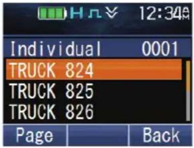
Full Color White
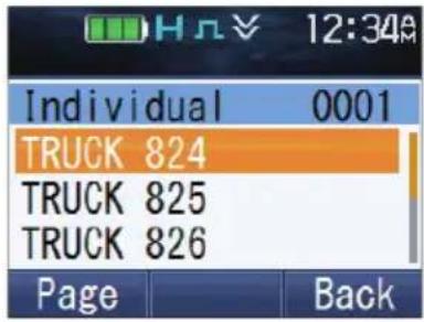
Monochrome Black
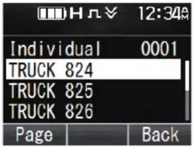
Monochrome White
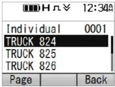
To select a Color Scheme:
1 Press the key programmed as [Menu] to enter Color Scheme Mode using the Menu Mode.
2 Press the [▲] and [▼] keys to select your desired color scheme.
3 Press the [☐] or [*key to confirm your selection.
Note:
- The Color Scheme setting is reflected in the color of the logo display during startup {p. 3}. However, this setting does not affect the display color of the Custom Start-up Screen.
BATTERY INFORMATION DISPLAY
You can check the detailed information, such as charging condition and temperature, of the Intelligent Battery installed on your transceiver.
1 Press the key programmed as [Menu] to enter Battery Information Display Mode using the Menu Mode.
• The battery information display appears.
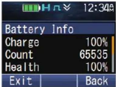
2 Press the [▲]/[▼] keys to scroll up or down the screen.
The following information is available for checking.
| Item | Menu Display | Range Description | |
| Current Charge*1 | Charge 0 – | 100 [%] | Displays the charging status of the rechargeable battery. |
| Cycle Count *2 | Count 0 – 6 | 5535 | Displays the accumulated number of times the battery charges and discharges. |
| Battery Health *3 | Health 0 – | 100 [%] | Displays the degradation of the rechargeable battery. |
| Current Voltage Voltage | 0 – 12.00 [V] | Displays the voltage of the rechargeable battery. | |
| Temperature Temp. | Celsius:-60.0 – 100.0 [°C]Fahrenheit:-76.0 – 212.0 [°F] | Displays the internal temperature of the rechargeable battery.The temperature is displayed in Celsius (°C) or Fahrenheit (°F) depending on the setting programmed by the dealer. | |
| Chemistry Chem. | Li-ion, Ni-MH | Displays the battery type. | |
| Serial Number Serial | 10-digit alphanumeric characters | Displays the serial number of the rechargeable battery. | |
| Model Name Model | KNB-L1, KNB-L2,KNB-L3, KNB-N4,KNB-LS5 orKNB-LS6 | Displays the model of the rechargeable battery. | |
| Date of First Use *4 | 1st Used Year/Month/Day | Displays the date the rechargeable battery was first used.The date style follows the setting programmed by your dealer. | |
| Battery Alias *4 | Alias | 20 alphanumeric characters and symbols, or 20 bytes of ASCII characters | Displays the name and information entered for the rechargeable battery. |
*1 Current Charge indicates the current remaining capacity of the rechargeable battery in percentage (%). A fully charged rechargeable battery is 100%.
A fully charged rechargeable battery of capacity 2600 mAh, for example, with a remaining capacity of 1300 mAh is displayed as 50 %. However, as the battery deteriorates over time, a fully charged rechargeable battery is displayed as 100 % even if the fully charged capacity falls from 2600 mAh to 2000 mAh.
*2 Cycle Count is the number of times the equivalent of 90 % of a rechargeable battery's nominal capacity is used. Cycle Count is not the actual number of times the battery has been charged and discharged.
The capacity of a rechargeable battery to discharge degrades over time. When the amount discharged is equivalent to the nominal capacity, it is counted as 1 Cycle Count.
For example, if 100 % of a rechargeable battery with a nominal capacity of 2000 mAh is completely discharged in one usage, the Cycle Count increases by 1. If approximately 14 (500 mAh) of the battery capacity is discharged in one usage, and the battery is used four times (500 mAh x 4 = 2000 mAh), the Cycle Count increases by 1.
It is recommended to replace the battery once the Cycle Count reaches 500 times.
*3 Battery Health indicates the capacity of a full charge in percentage (%). 100 % for a full charge capacity when the battery is first used. A rechargeable battery deteriorates over time after repeated charging and discharging, and cannot maintain a full charge as a new battery.
For example, if a rechargeable battery has a full charge capacity of 2600 mAh when it was first used, and the current full charge capacity is 2340 mAh, the Battery Health will be 90 %.
It is recommended to replace the battery once the Battery Health reaches 50%.
*4 KNB-N4 does not support Date of First Use and Battery Alias, these items are displayed as “--” even if the information has been read without error.
Note:
- “—” is displayed if the information of the Intelligent Battery cannot be obtained.
- The battery information is not updated while the Battery Information Display screen is displayed.
MULTI LANGUAGE
Your transceiver is equipped with multiple language support feature. You can change the language of the text display on the LCD screen and the language of the voice announcement. There are three languages available for selection; however, the languages selectable are dependent on the dealer setting. For details, consult your dealer.
1 Press the key programmed as [Menu] to enter Language Mode using the Menu Mode.
2 Press the [▲]/[▼] keys to select the desired language.
3 Press the [☐] or [★key to confirm and exit Language Mode.
- The language of the LCD screen display and the voice announcement changes to the language selected.
Note:
- The language of the voice announcement may not change depending on the dealer setting. For details, consult your dealer.
FleetSync: ALPHANUMERIC 2-WAY PAGING FUNCTION
FleetSync is an Alphanumeric 2-way Paging Function, and is a protocol owned by JVC KENWOOD Corporation. FleetSync enables a variety of paging functions on your transceiver, some of which depend on dealer programming.
Note:
• This function is available only in analog operation.
SELCALL (SELECTIVE CALLING)
A Selcall is a voice call to a station or group of stations.
■ Transmitting
1 Select your desired zone and channel.
2 Press the key programmed as [Individual]/ [Individual + Status]/ [Individual + Short Message]/ [Group]/ [Group + Status] or [Group + Short Message] to enter Selcall Mode.
Alternatively, press the key programmed as [Menu] to enter Selcall Mode using Individual/Individual + Status/Individual + Short Message/Group/Group + Status or Group + Short Message in the Menu Mode.
3 Press the [▲] and [▼] keys to select the station you want to call.
- On full key model transceivers, if Manual Dialing is enabled, you can enter the station ID by using the keypad.
4 Press the PTT switch and begin your conversation.
Receiving
An alert tone will sound and the transceiver will enter Selcall mode. The calling station's ID will appear when a Selcall is received. You can respond to the call by pressing the PTT switch and speaking into the microphone.
■ Identification Codes
An ID code is a combination of a 3-digit Fleet number and a 4-digit ID number. Each transceiver has its own ID.
- Enter a Fleet number (100 \~ 349) to make a fleet call.
- Enter an ID number (1000 \~ 4999) to make an individual call in your fleet.
- Enter a Group ID (which is programmed in the FPU) to make a group call.
- Enter a Fleet number followed by an ID number to make an individual call in your desired fleet (Inter-fleet call).
- Select "ALL" Fleet and "ALL" ID to make a call to all units (Broadcast call).
- Select "ALL" Fleet and enter an ID number to make a call to the selected ID in all fleets (Supervisor call).
STATUS MESSAGE
You can send and receive 2-digit Status messages which may be decided in your talk group. Messages can contain up to 16 alphanumeric characters. Status messages range from 10 to 99 (80 \~ 99 are reserved for special messages).
A maximum of 250 received messages can be stored in the stack memory of your transceiver. These saved messages can be reviewed after reception. Depending on your dealer settings, when the stack memory is full, either the oldest message will be erased when a new message is received or the new message will not be stored in the stack memory. The indicator appears when a message is stored in the stack memory.
■ Transmitting
1 Select your desired zone and channel.
2 Press the key programmed as [Status] to enter Status mode (proceed to step 5), or [Individual + Status]/[Group + Status] to enter Selcall mode (proceed to step 3).
3 Press the [▲] and [▼] keys to select the station you want to call.
- If Manual Dialing is enabled, you can enter a station ID using the keypad or the [▲]/[▼] key. When using the [▲] and [▼] keys, cycle through the digits to select a digit, then press the [■] or [ ] key to set the digit and move the cursor to the right. Repeat this process until the entire ID is entered.
4 Press the [▶] key to enter Status mode.
5 Press the [▲] and [▼] keys to select the status you want to transmit.
- If Manual Dialing is enabled, you can enter a status ID using the keypad or the [▲]/[▼] key (refer to step 3, above).
6 Press the PTT switch to initiate the call.
- “Complete” appears on the display when the status has been successfully transmitted.
Receiving
The indicator will flash and a calling ID and status message will appear when a Status call is received. Press any key to return to normal operation.
■ Reviewing Messages in the Stack Memory
1 Press the key programmed as [Stack], or press and hold the key programmed as [Individual], [Group], [Status], [Individual + Status], or [Group + Status] to enter Stack mode.
- The category list is displayed.
However, depending on the stack settings programmed by your dealer, the individual list (Caller ID, Status Message or Short Message) may be displayed instead of the category list. For details on the stack settings, consult your dealer.
• The categories are identified as follows:
2 Press the [▲] and [▼] keys to select the desired category, then press the [□] or [★key.
- The Caller ID list, Status Message list or Short Message list is displayed according to the category selected. Pressing the [◀]/[▶] keys allows you to cycle the display information as follows.
- While Caller ID list is displayed:
[◀]: Caller ID > CH > Time Stamp
[▶]: Caller ID > Time Stamp > CH
- While Status Message list or Short Message list is displayed:
[◀]: Message > Caller ID > CH > Time Stamp
[▶]: Message > Time Stamp > CH > Caller ID
- To delete the selected message, press the [ ] or [#] key. To delete all messages, press and hold the [ ➕ ] or [#] key for one second.
3 Press [▲] to return to normal operation.
SHORT MESSAGES
This transceiver can receive short data messages which contain a maximum of 48 characters.
- On full key model transceivers, short messages received are displayed the same as Status messages and are stored in the same stack memory. A maximum of 32, 64 or 128 short messages can be stored in the stack memory depending on the Short Message Stack setting of each system.
LONG MESSAGES
To send and receive long messages, you must connect the transceiver to a PC. Ask your dealer for details.
- Long messages can contain a maximum of 4096 characters.
GPS REPORT
GPS data can be manually transmitted by pressing the key programmed as [Send the GPS Data], or by accessing the Menu {p. 14}. If set up by your dealer, GPS data may be automatically transmitted at a preset time interval.
- When using the GPS function, you must first connect the VHF/ GPS antenna or UHF/ GPS antenna.
5-TONE SIGNALING
5-tone Signaling is enabled or disabled by your dealer. This function opens the squelch only when the transceiver receives the 5 tones programmed in your transceiver. Transceivers that do not transmit the correct tones will not be heard.
SELCALL (SELECTIVE CALLING)
A Selcall is a voice call to a station or group of stations.
■ Transmitting
1 Select your desired zone and channel.
2 Press the key programmed as [Individual]/ [Individual + Status]/ [Individual + Short Message]/ [Group]/ [Group + Status] or [Group + Short Message] to enter Selcall Mode.
Alternatively, press the key programmed as [Menu] to enter Selcall Mode using Individual/Individual + Status/Individual + Short Message/Group/Group + Status or Group + Short Message in the Menu Mode.
3 Press the [▲] and [▼] keys to select the station you want to call.
- On full key model transceivers, you can enter the station ID using the keypad.
4 Press the key programmed as [Call 1] to [Call 6] and begin your conversation.
Note:
- You can also use the keys programmed as [Digit 1x Down], [Digit 1x Up], [Digit 10x Down], and [Digit 10x Up] to adjust the Selcall number. [Digit 1x Up] and [Digit 1x Down] increases and decreases the Selcall number by 1 respectively each time the key is pressed. [Digit 10x Up] and [Digit 10x Down] increases and decreases the Selcall number by 10 respectively each time the key is pressed.
Receiving
When a call containing the correct tones is received, the transceiver will enter Selcall mode. An alert tone will sound and the calling station's ID appears on the display. Press any key to return to normal operation.
STATUS MESSAGE
You can send and receive Status messages which may be decided in your talk group. Messages can contain up to 16 alphanumeric characters.
A maximum of 250 received messages can be stored in the stack memory of your transceiver.
Transmitting
1 Select your desired zone and channel.
2 Press the key programmed as [Status] to enter Status mode (proceed to step 5), or [Individual + Status]/ [Group + Status] to enter Selcall mode (proceed to step 3).
3 Press the [▲] and [▼] keys to select the station you want to call. - On full key model transceivers, you can enter the station ID using the keypad.
4 Press the [▶] key to enter Status mode.
5 Press the [▲] and [▼] keys to select the status you want to transmit.
- You can enter a status ID using the keypad or the [▲]/[▼] key (refer to step 3, above).
6 Press the key programmed as [Call 1] to [Call 6] to initiate the call.
Receiving
The indicator will flash and a calling ID and status message will appear when a Status call is received. Press any key to return to normal operation.
■ Reviewing Messages in the Stack Memory
1 Press the key programmed as [Stack] to enter Stack mode.
• The category list is displayed.
• The categories are identified as follows:
2 Press the [▲] and [▼] keys to select the desired category, then press the [□] or [★key.
- The Caller ID list, Status Message list or Short Message list is displayed according to the category selected. Pressing the [◀]/[▶] keys allows you to cycle the display information as follows.
- While Caller ID list is displayed:
[◀]: Caller ID > CH > Time Stamp
[▶]: Caller ID > Time Stamp > CH
- While Status Message list or Short Message list is displayed:
[◀]: Message > Caller ID > CH > Time Stamp
[▶]: Message > Time Stamp > CH > Caller ID
- To delete the selected message, press the [→] or [#] key. To delete all messages, press and hold the [for [#] key for one second.
3 Press [ ] to return to normal operation.
VOICE OPERATED TRANSMISSION (VOX)
VOX can be activated or deactivated by your dealer. VOX operation allows you to transmit hands-free.
Note:
- To operate VOX, you must use an optional headset.
VOX Gain Level
Sets the Mic input sensitivity of the VOX operation.
1 Connect a headset to the transceiver.
2 Press the key programmed as [VOX].
• The current VOX Gain level appears on the display.
3 Press the [▲] or [▼] key to increase or decrease the VOX Gain level.
• The VOX Gain can be adjusted from levels 1 to 10.
4 While adjusting the level, speak into the headset microphone to test the sensitivity level. (Your voice is not transmitted during this test procedure.)
- When sound is recognized, the LED lights yellow.
5 Press the [☐] key to save your new setting.
VOX Operation
1 Connect a headset to the transceiver.
- The VOX function does not activate when a headset is not connected to the accessory terminal of the transceiver.
2 Press and hold the key programmed as [VOX].
- Alternatively, you can press the key programmed as [Menu] to enter VOX Mode using the Menu Mode.
- A beep will sound and the indicator appears on the display.
3 When you finish speaking, transmission ends.
To turn the VOX function OFF, press and hold the key programmed as [VOX] key again.
- A beep will sound and the 📁 indicator will disappear from the display.
Note:
- If a speaker/ microphone is connected to the transceiver while VOX is ON, and the VOX Gain Level is set to a sensitive level, louder received signals may cause the transceiver to transmit.
The Time-out Timer can be activated only on Conventional channels and in NXDN Trunking system. It is used to prevent any caller from using a channel for an extended period of time.
If you continuously transmit for a period of time that exceeds the programmed time, the transceiver will stop transmitting and an alert tone will sound. To stop the tone, release the PTT switch. Your dealer can program the TOT time in the range of 15 seconds to 20 minutes.
If programmed by your dealer, a pre-alert tone will sound before the timer expires. Also, if programmed by your dealer, you may have to wait for a short duration before you can continue to transmit. If you press the PTT switch before the timer has been reset, an alert tone will sound and the transceiver will not enter transmit mode.
BATTERY SAVER
The Battery Saver function can be activated only on Conventional channels. When activated, this function decreases the amount of power used when a signal is not being received and no operations are being performed (no keys are being pressed and no switches are being turned).
While the channel is not busy and no operation is performed for 5 seconds, Battery Saver activates. When a signal is received or an operation is performed, Battery Saver is disabled.
LOW BATTERY WARNING
Low Battery Warning alerts you when the battery needs to be recharged.
Your dealer can set an alert tone to sound and the LED indicator to blink red when the battery power is low. The battery power indicator displays the battery power remaining, as illustrated below.

High

Sufficient

Low

Very low
When the battery power is very low, recharge or replace the battery pack.
SIGNAL STRENGTH INDICATOR
The signal strength indicator displays the strength of received calls.

Strong signal

Sufficient signal

Weak signal

Very weak signal

Out of service range
(Appears on NXDN Trunking and P25 Trunking channels only)
COMPANDER
The compander can be programmed only for specific analog channels. If it has been programmed by your dealer, transmitted signals are compressed before being sent and received signals are expanded when they arrive.
- Your dealer must set the commander for both the transmit side and the receive side in order for the commander to operate.
- The indicator appears on the display when the commander activates.
This background feature allows higher clarity of signals, avoiding excessive noise and interference. This feature is not used on digital channels, as they are not susceptible to noise and interference.
BUSY CHANNEL LOCKOUT (BCL)
On Conventional channels, if BCL is set up by your dealer, you will be unable to transmit on the channel if it is already in use. Under these circumstances, use a different channel or wait until the channel becomes free.
However, if BCL Override has also been programmed, you can transmit over the current signal:
1 Press and hold the PTT switch.
• If the channel is already in use, a warning tone will sound.
2 Release the PTT switch, then press and hold the PTT switch again within half a second.
3 Speak into the transceiver as you would during a normal call.
OUT OF RANGE
On P25 Trunking and NXDN Trunking channels, if set up by your dealer, the transceiver will indicate when it is out of range. When it can no longer communicate with any site, an out of range tone sounds and “Out of Range” appears on the display. If enabled by your dealer, an In-service Tone will sound when an available control channel is detected after the out of range tone has sounded. For details on the in-service tone, consult your dealer.
SITE TRUNKING (P25 Trunking)/ NETWORK FAILURE (NXDN Trunking)
On Trunking channels, if set up by your dealer, the transceiver will indicate a network condition on the registered site. "Site Trunk" (P25)/ "Network Fail" (NXDN) appears on the display when the transceiver receives a network disabled message.
CONTROL CHANNEL HUNT
On P25 Trunking and NXDN Trunking channels, the transceiver must search for a control channel. While searching for a control channel, no signals can be received. The search begins automatically when you change to a Trunking channel.
- While hunting for a channel, the antenna indicator will flash. When a control channel has been found, the antenna indicator remains on the display without flashing.
VOICE ANNOUNCEMENT
An audio voice will be announced as below by dealer setting.
- When changing the zone and/or channel, the new zone and channel number are announced.
- When changing the status, the new status is announced.
- When changing the function setting, the new setting is announced.
VIBRATOR
When an optional external vibrator (KCT-48VU External Vibration Unit) is installed, the vibrator function will alert you when an optional signaling call is received. Press the key programmed as [Vibrator] or access the Menu {p. 14} to turn the Vibrator function on and off.
Bluetooth
If your transceiver has been programmed with the Bluetooth function, you can connect your transceiver with a Bluetooth headset to make hands-free calls.
The Bluetooth specifications are as follows.
Version : Version 4.0 (Models other than Basic key model)
Version 3.0 (Basic key model)
Power class : Class 2 (2.5 mW, up to 10 m)
Profile : Headset Profile (HSP), Serial Port Profile (SPP), Heart Rate Service,
Automatic Injury Detection Service, Battery Service, Device
Information Service
Refer to the table below for more details on each profile.
Device class : Phone
Note:
- The communication distance varies depending on the obstacles between the communication devices and the radio wave conditions.
- Only headsets which support the Headset Profile (HSP) certified by Bluetooth SIG can be used with the transceiver. However, operations are not guaranteed in all headsets.
- Refer to the following URL for details on the Bluetooth devices operationally tested by KENWOOD:
http://manual2.jvckenwood.com/com/help_ref/nx5000_series/compatible_model_list/CNMJSYnnzoitpv.html If you wish to use a Bluetooth device that is not operationally tested, please consult your dealer.
If the Bluetooth Data setting is enabled by your dealer, you can use the Serial Port Profile, Heart Rate Service, Automatic Injury Detection Service, Battery Service and Device Information Service.
| Profile | Description |
| Headset Profile (HSP) Headset Profile provides support for Bluetooth headsets to be used with this transceiver for making voice calls. | |
| Serial Port Profile (SPP) Serial Port Profile allows this transceiver to connect to a Bluetooth-enabled PC without using a programming cable to communicate with the Field Programming Unit (FPU) or to use the PC Interface Protocol. For details on the Field Programming Unit (FPU) or PC Interface Protocol, consult your dealer. | |
| Heart Rate Service Heart Rate Service is a function that sends the heart rate [bpm] to the transceiver from a Bluetooth-enabled device (such as heart rate monitor) that supports Heart Rate Service. The transceiver can send the heart rate via Status or activate the Emergency operation. When a Status request message is received from the Base Station, the transceiver can respond with the heart rate via Status or send the heart rate together with the GPS data via Status. | |
| Profile Description | |
| Automatic Injury Detection Service | Automatic Injury Detection Service is a function that notifies the transceiver from the Bluetooth-enabled device when the Bluetooth-enabled device that supports Automatic Injury Detection Service is damaged. Up to two Bluetooth-enabled devices can be connected to the transceiver at the same time. To use this service, it is necessary to enable the Injury Detection setting. For details, consult your dealer. |
| Battery Service The transceiver displays the remaining battery power [%] of the Bluetooth-enabled device on the screen when a Bluetooth-enabled device that supports Heart Rate Service or Automatic Injury Detection Service is connected to the transceiver. | |
| Device Information Service The transceiver displays the information of the Bluetooth-enabled device such as manufacturer name and model number on the screen when a Bluetooth-enabled device that supports Heart Rate Service or Automatic Injury Detection Service is connected to the transceiver. | |
■ Selecting the Bluetooth headset type
You can select the type of Bluetooth headset to be connected to the transceiver via HSP connection.
1 Press the key programmed as [Menu] to enter Bluetooth Headset Connection Type Mode using the Menu Mode.
2 Press the [▲] and [▼] keys to select the desired headset type.
3 Press the [☐] or [★key to confirm the selection.
- The selection is backed up and will take effect the next time the transceiver is turned on.
Note:
- If you exit the Bluetooth Headset Connection Type Mode without pressing the [ ] or [ ] * key, the headset type selected will not be reflected in the menu setting.
- Most Bluetooth headsets can be connected and operated by selecting "Headset 1" in "Bluetooth Headset Connection Type". For some headsets, it is necessary to select "Headset 2". For details, refer to the following URL:
http://manual2.jvckenwood.com/com/help_ref/nx5000_series/compatible_model_list/CNMJSYnnzoitpv.html
TURNING Bluetooth ON/ OFF
Press the key programmed as [Bluetooth] to turn the Bluetooth function on or off. Alternatively, press the key programmed as [Menu] to enter Bluetooth Mode using the Menu Mode.
Press the [▲] and [▼] keys to select "On" or "Off".
Press the [☐] or [*key to confirm your selection.
- “appears on the display when the Bluetooth function is turned on. If a Bluetooth device is already connected to your transceiver,” appears on the display.
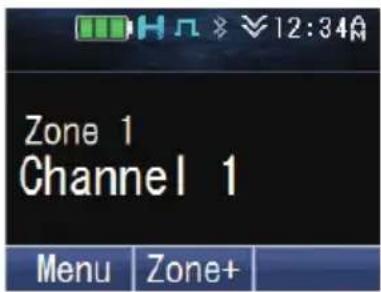
FINDING Bluetooth DEVICES
Your transceiver can automatically search for Bluetooth devices.
Note:
- Put your Bluetooth headset into pairing standby mode beforehand.
1 Press the [key to enter Menu Mode.

2 Press the [☐] key to select the Bluetooth category.
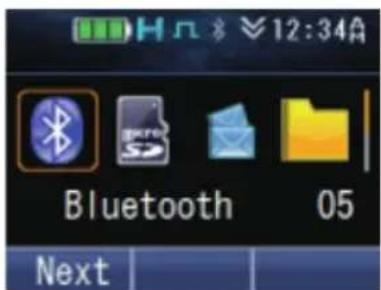
3 Press the [☐key or the [▲] and [▼] keys to select "BT Device".
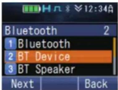
4 Press the [key or the [▲] and [▼] keys to select "Find Device".
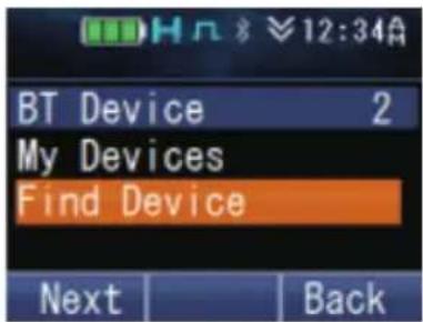
The transceiver starts to search for available Bluetooth devices. Up to 16 devices can be found and listed on the display.
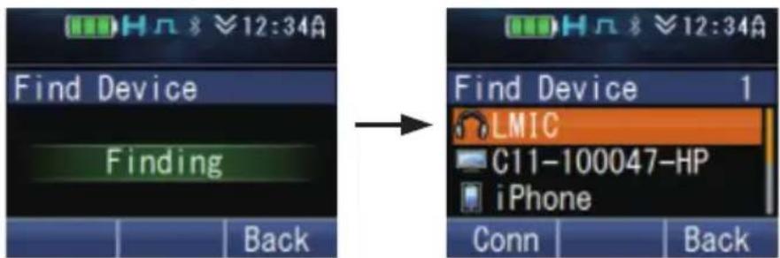
- The search will end after approximately 30 or 40 seconds (depending on whether or not the Bluetooth Data setting is enabled by the dealer), or when 16 devices have been found.
■ Pairing Bluetooth devices
1 Press the [▲] and [▼] keys to select the device to connect to. In this case, select the headset device.
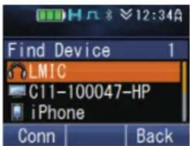
2 Press the [☐] or [*key to connect.
3 Press the [☐] or [*key to start pairing.
Alternatively, you can pressed the key programmed as [Bluetooth Connect/Disconnect].
• The LED indicator blinks in blue.
- For Bluetooth devices that does not support Simple Secure Pairing, you need to enter a Personal Identification Number (PIN) code. You need to operate the Bluetooth headset to proceed with pairing.
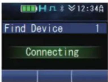
When pairing is complete, your transceiver will connect to the Bluetooth headset. When the connection is established, you can perform hands-free call.
- The “” indicator appears on the display.
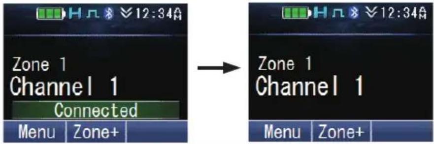
Note:
- Once the headset has been paired, it can be used automatically with the transceiver the next time the transceiver and headset are powered on. If the headset cannot be used automatically, connect manually using the My Device setting in the Bluetooth menu of the transceiver.
(Some headset models cannot be used automatically.)
• Up to 10 Bluetooth devices can be registered to your transceiver. - The pressing of the key programmed as Bluetooth Connect/ Disconnect does not affect the status of the Bluetooth connection via Serial Port Profile.
■ Making hands-free call

Press the PTT switch to activate the microphone of the Bluetooth headset.
Note:
- The volume level can only be adjusted on the Bluetooth headset. The volume control of the transceiver does not function. However, if the audio is set to output from the built-in speaker of the transceiver in the Bluetooth Speaker setting, the volume level is controlled by the transceiver.
• The microphone sensitivity can be set using the External Mic Sense function.
■ Connecting to a PC
To connect to a PC using the Serial Port Profile, you have to make a request for connection from the PC to your transceiver. The transceiver will start to connect once it received the request from the PC.
Once the connection has been established, your transceiver can start communicating with the Field Programming Unit (FPU) or you can use the PC Interface Protocol.
- The “” indicator appears on the display.
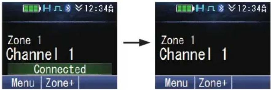
The transceiver transits to each mode when the FPU communication begins. To use the PC Interface Protocol, run the PC commands.

USEFUL FUNCTIONS
There are some useful functions on your transceiver which allows you to display information of the Bluetooth devices registered to the transceiver and to switch the speaker audio output.
■ Connecting/ Disconnecting/ Deleting a registered device using My Devices
Press the key programmed as [Menu] to enter Bluetooth My Devices Mode using the Menu Mode.
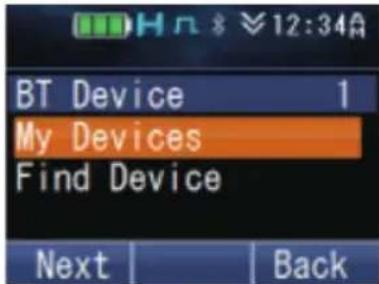
To connect a device:
1 Press the [☐] key or the [▲] and [▼] keys to select the device to connect to.
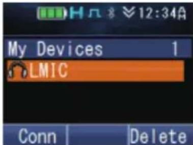
2 Press the [☐] or [*key to connect.
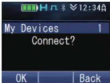
3 Press the [flor[] key to confirm the connection.
- The LED indicator blinks in blue while the transceiver is connecting to the device, "Connecting" appears on the display.
"Connected" appears when the connection is established.
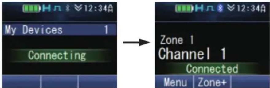
To disconnect a device:
1 Press the [☐] key or the [▲] and [▼] keys to select the device to disconnect.
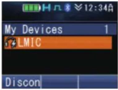
2 Press the [☐] or [*key to disconnect.
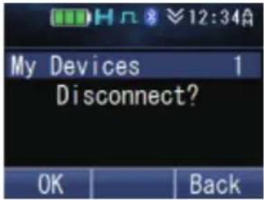
3 Press the [flor[] key to confirm the disconnection.
- The “Indicator and “Disconnected” appear on the display.

To delete a device:
Note:
• Make sure the device to be deleted has been disconnected.
1 Press the [☐] key or the [▲] and [▼] keys to select the device to delete.
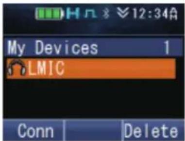
2 Press the [→] or [#] key to delete.

3 Press the [flor[] key to confirm.
- The selected device will be deleted. "BT No Device" appears when there is no other registered device.
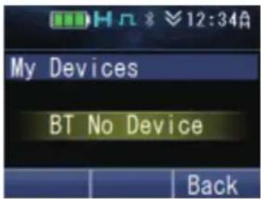
Note:
• To delete all the registered devices, press and hold the [for[#] key in Step 2.
- Checking the information of the devices
1 Press the key programmed as [Menu] to enter Bluetooth My Devices Mode using the Menu Mode.
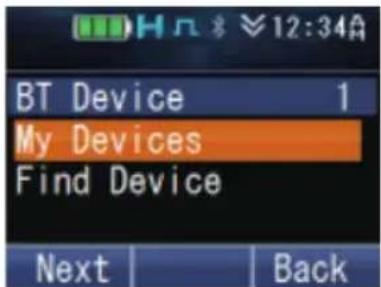
2 Press the [▲] and [▼] keys to select the device to display its information.

3 Press the [▶] key followed by the [▲] and [▼] keys to switch between the different information displays as described below.
BT Name : The name of the Bluetooth device.
BT Address : The address of the Bluetooth device.
Class : The equipment classification of the Bluetooth device. Refer to the following table for more details.
Heart Rate : The heart rate [bpm] from a registered Bluetooth-enabled device that supports Heart Rate Service.
Injury Status : Indicates whether or not a registered Bluetooth-enabled device that supports Automatic Injury Detection Service is damaged.
Charge : The remaining battery power of a registered Bluetooth-enabled device that supports Battery Service.
Manufacturer : The manufacturer's name of a registered Bluetooth-enabled device that supports Device Information Service.
Model : The model number of a registered Bluetooth-enabled device that supports Device Information Service.
Serial : The serial number of a registered Bluetooth-enabled device that supports Device Information Service.
Hardware Ver.: The hardware version of a registered Bluetooth-enabled device that supports Device Information Service.
Firmware Ver. : The firmware version of a registered Bluetooth-enabled device that supports Device Information Service.
Software Ver. : The software version of a registered Bluetooth-enabled device that supports Device Information Service.
| Device Class Disconnected | Connected | |
| Audio/Video |  |  |
| Phone |  |  |
| Computer |  |  |
| LAN/Network |  |  |
| Peripheral | ||
| Imaging | ||
| Wearable | ||
| Toy | ||
| Health |
Note:
• You can also check the information of the devices in the Find Device mode.
- The icons listed in the above table indicate the connection status of the Headset Profile, Heart Rate Service and Automatic Injury Detection Service. They are not applicable to the Serial Port Profile connection.
■ Switching the speaker audio output
You can switch the audio output between the speaker of the transceiver and the Bluetooth headset.
Press the key programmed as [Bluetooth Speaker] to change the setting (“Off” or “Only”).
Alternatively, press the key programmed as [Menu] to enter Bluetooth Speaker Mode using the Menu Mode. Press the [▲] and [▼] keys to select "Off" or "Only".
Off : Audio is output from the built-in speaker of the transceiver.
Only : Audio is output from the speaker of the Bluetooth device.
Press the [☐] or [♦key to confirm your selection.
NOTIFICATION DISPLAY
| Display Cause | |
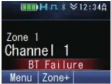 (Display for 1 second) (Display for 1 second) | The integrated circuit (IC) which enables the Bluetooth function is not working properly. |
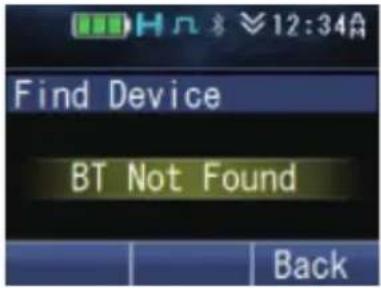 | No device is found in the Bluetooth Find Device Mode. |
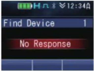 (Display for 1 second) (Display for 1 second) | There is no response from the Bluetooth device on the request for pairing, Headset Profile (HSP) connection, Serial Port Profile (SPP) connection or Bluetooth Low Energy (Heart Rate Service, Automatic Injury Detection Service) connection. |
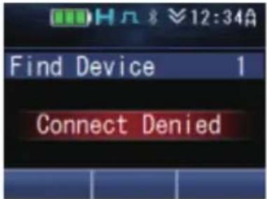 (Display for 1 second) (Display for 1 second) | The Bluetooth device has rejected a request for pairing, Headset Profile (HSP) connection or Bluetooth Low Energy (Heart Rate Service, Automatic Injury Detection Service) connection. |
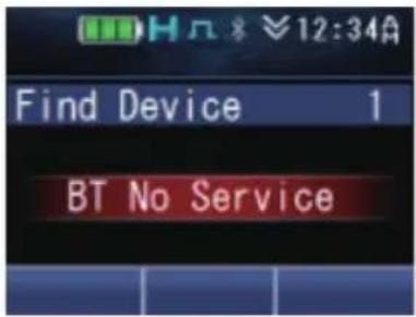 (Display for 1 second) (Display for 1 second) | The Bluetooth device does not support Headset Profile (HSP) connection. |
microSD CARD & BUILT-IN MEMORY
You can perform voice recording, voice playback and GPS Data Storage using the built-in memory or a microSD card.
USING THE microSD CARD
Insert the microSD card into the transceiver and turn on the transceiver. The indicator lights up on the display when the microSD card is recognized by the transceiver. Recordings and data will be stored on the microSD card.
When using the microSD card for the first time on the transceiver, it is necessary to format the card.
- All existing files on the microSD card will be deleted upon formatting. Folders for storing the recordings and data will be created in the microSD card.
■ Folder structure and file naming
Voice files and GPS data files are stored in their respective folders. Up to 250 files can be stored in each folder.
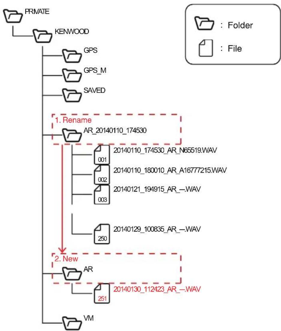
flowchart
graph TD
    A["PRMATE"] --> B["KENWOOD"]
    B --> C["GPS"]
    B --> D["GPS_M"]
    B --> E["SAVED"]
    C --> F["1. Rename"]
    D --> F
    E --> F
    F --> G["AR_20140110_174530"]
    G --> H["20140110_174530_AR_N65519.WAV"]
    G --> I["001"]
    G --> J["002"]
    G --> K["003"]
    G --> L["20140110_180010_AR_A16777215.WAV"]
    G --> M["250"]
    G --> N["20140121_194915_AR_.WAV"]
    G --> O["251"]
    P["VM"] --> Q["20140130_112423_AR_.WAV"]
    Q --> R["2. New"]
| Folder Type | Description |
| AR *1 | Stores voice files recorded using Auto Recording. |
| VM *1 | Stores voice files recorded using Voice Memo. |
| SAVED | Voice files recorded using Auto Recording and Voice Memo can be stored in this folder manually. Refer to “To save a recording” {p. 78}. |
| GPS *2 | Stores GPS data files saved using GPS Data Storage (Auto). |
| GPS_M *3 | Stores GPS data files saved using GPS Data Storage (Manual). |
*1 If the folder has reached its maximum limit of 250 files, the current folder is automatically renamed and a new folder is created when storing the 251st file. Up to 2000 folders can be created.
*2 Only one folder is available for storing GPS data files saved using GPS Data Storage (Auto). If the folder has reached its maximum limit of 250 files, the oldest file in the folder is deleted when storing the 251st file.
*3 Only one folder is available for storing GPS data files saved using GPS Data Storage (Manual). Up to 2000 GPS data can be saved in a file. If the folder has reached its maximum limit of 250 files and the 250th file contains 2000 data, no further GPS data can be saved.
Files stored in each folder are automatically named.

① Date saved
The year, month and day the file is saved.
② Time saved
The hour, minute and second the file is saved.
③ Function Indicates the function used to save the file.
AR : Auto Recording
VM : Voice Memo
GPS : GPS Data Storage (Auto)
GPS_M : GPS Data Storage (Manual)
④ Call origin (Auto Recording and Voice Memo only) ID information of the call origin when recording starts. “---” is displayed when no ID information is available.
⑤ File extension Voice files are saved as “.WAV”, and GPS data files are saved as “.TXT”.
Note:
• The date format and time format settings do not apply to the file name.
- When the built-in clock stops or the clock has not been set, the date saved ^① will become "00000000" and the time saved ^② will become a file number.
The file number is determined as follows.
- If there are no files in the destination folder where the file is to be saved, a file name with the file number "000001" is saved.
- If there are files in the destination folder where the file is to be saved, a file name with the file number made up of the biggest file number of the existing files + 1 is saved.
The file numbers that can be used is 000001 to 009999.
■ microSD card recording time
The estimated maximum recording time for Voice Memo and Auto Recording according to the capacity of the microSD card is as follows.
| microSD Card Capacity Estimated Recording Time (Max) | |
| 2 GB 35 hours | |
| 4 GB 70 hours | |
| 8 GB 140 hours | |
| 16 GB 280 hours | |
| 32 GB 560 hours | |
■ Warnings for the remaining capacity of microSD card
Low SD Memory
If Low Memory Warning is enabled by your dealer, “Low SD Memory” appears on the display for 1 second when the remaining capacity of the microSD card is 10 % or less.
◆ Memory Full
"Memory Full" appears on the display for 1 second under any of the following conditions.
| Auto Recording When any of the following conditions is satisfied.The remaining capacity of the microSD card is less than 2 times the Maximum Recording Length.When the First-in First-out Deletion function is disabled and there are 250 files in the 2000th folder. | |
| Voice Memo When any of the following conditions is satisfied.The remaining capacity of the microSD card is less than 2 times the maximum recording time of 10 minutes.When the First-in First-out Deletion function is disabled and there are 250 files in the 2000th folder. | |
| GPS Data Storage (Auto) When any of the following conditions is satisfied.The remaining capacity of the microSD card is less than 43 MB when there is no GPS data file in the GPS folder with the same date as the current saving date.The remaining capacity of the microSD card is less than 128 KB when there is a GPS data file in the GPS folder with the same date as the current saving date. | |
| GPS Data Storage (Manual) When all the following conditions are satisfied.NMEA of any of the Record Format (Manual/Auto) is enabled.The Save GPS Data key, GPS Position Display key, Menu key for executing Save GPS Data or Menu key for executing GPS Position Display is configured.The remaining capacity of the microSD card is less than 1 KB. Or there is no GPS data file in the GPS_M folder with the same date as the current saving date and there are 250 GPS data files in the folder. |
■ Formatting the microSD card
1 Press the key programmed as [Format SD Card] to enter Format SD Card mode. • “You will lose all data on the card.” appears on the display. Press the []key.
2 Select "Start" and press the [key to format the card.
- When formatting is complete, the indicator lights up and "Complete" appears on the display. Folders for storing the recorded files are created on the microSD card.
Auto Recording
Auto Recording records and retains your last conversation, allowing you to catch what you may have missed hearing during the conversation.
If activated, the auto recording function will continuously record all transmitted and received signals to the built-in memory or microSD card according to the maximum recording length set.
• The indicator blinks while recording is in progress.
When recording is made to the built-in memory, the backup timing of the voice recording varies according to the First-in First-out Deletion setting. If First-in First-out Deletion is enabled, the recording is backed up when the transceiver is turned off using the Power switch. If disabled, the recording is backed up each time a recording is made. For details on the First-in First-out Deletion function, consult your dealer.
Note:
• Recording stops when the maximum recording length is reached.
- If the First-in First-out Deletion function is disabled, new recordings cannot be made when the memory in the built-in memory or microSD card is full. “Memory Full” appears on the display for 1 second.
- If the First-in First-out Deletion function is enabled and recording is made to the built-in memory, the transceiver turns off without backing up the recording when it is turned off in the following situations:
- When the battery runs out
- When the battery pack is removed
- You can play back the voice recording in Playback mode, or delete the recording if necessary.
- If Auto Recording is used concurrently with the GPS Data Storage function, the beginning of the audio recorded by Auto Recording may be clipped off.
Voice Memo
Voice Memo allows you to record audio near the transceiver manually. Maximum recordable time per Voice Memo is 10 minutes. The voice files are stored on the microSD card.
If a speaker microphone such as KMC-54WD is connected to the transceiver, the audio input to the microphone of the speaker microphone is recorded. Otherwise, the audio input to the microphone of the transceiver is recorded.
1 Press the key programmed as [Voice Memo] to enter Voice Memo mode.
Alternatively, press the key programmed as [Menu] to enter Voice Memo mode using the Menu Mode.
• Recording starts on the transceiver.
- The transceiver will exit Voice Memo mode and stop the recording automatically after 10 minutes into the recording.
2 To stop the recording manually, press the [☐] or [*key.
Note:
- Recording does not start when the key programmed as [Voice Memo] is pressed under the following conditions.
- Recognition of the microSD card by the transceiver is not complete.
- Formatting of microSD card is in progress.
- Deleting of voice files is in progress.
- If Voice Memo is used concurrently with the GPS Data Storage function, the beginning of the audio recorded by Voice Memo may be clipped off.
GPS Data Storage
GPS data can be stored either automatically in the built-in memory and microSD card or manually at your preferred timing in the microSD card.
■ GPS Data Storage (Auto)
The GPS data is stored temporarily in the transceiver RAM at every GPS Storage Interval from the GPS unit. The data will be written to the built-in memory and microSD card when more than three pieces of data are collected. The stored GPS data in the built-in memory can be sent from the transceiver via DMR/ NXDN Air Protocol or can be read on a PC.
Up to 7000 GPS data can be written to the built-in memory. In the case of microSD card, a maximum of 250 days of GPS data or the microSD card capacity allowable quantity can be written to it. Record Format (Manual/Auto) must be configured in order to write a GPS data to the microSD card. For more details, consult your dealer.
■ GPS Data Storage (Manual)
The GPS data can be manually stored in the microSD card using one of the key operations below.
- Press the key programmed as [Save GPS Data].
- Press the key programmed as [GPS Position Display] to enter the GPS Position Display mode, then press [☐or []. *
- Press the key programmed as [Menu] to enter Menu Mode to execute Save GPS Data or GPS Position Display.
A maximum of 250 days of GPS data or the microSD card capacity allowable quantity can be written to the microSD card. However, the data is not stored under the following conditions even when the key is pressed.
- When there is no GPS positioning.
- When the GPS function of the built-in GPS receiver is turned off.
- When the microSD card is not recognized properly.
- When the Memory Full conditions for GPS Data Storage (Manual) are satisfied. {p. 75}
Note:
• The data saved can be displayed using the GPS Position Display function.
Playback
You can play back the voice recordings recorded using Auto Recording and Voice Memo.
1 Press the key programmed as [Playback] to enter Playback mode.
Alternatively, press the key programmed as [Menu] to enter Playback mode using the Menu Mode.
- If a microSD card is not inserted in the transceiver, the voice recordings are listed on the display. Proceed to step 4.
- If a microSD card is inserted in the transceiver, the Saved (★), Auto Recording (○) and Voice Memo (○) folders where the voice recordings are stored are displayed. Only the folder with files stored in it is displayed.
2 Press the [▲] and [▼] keys to select the Auto Recording or Voice Memo folder, then press the [□] or [★key.
• The subfolders in the folder are listed on the display.
3 Press the [▲] and [▼] keys to select a folder, then press the [□] or [*] key.
• The voice recordings in the folder are listed on the display.
4 Press the [▲] and [▼] keys to move up and down the list.
5 Press the [☐] or [*key to play back.
- After playing back a recording, the transceiver will automatically play the next recording until the last recording on the list is played.
• To pause or resume playback, press the [ ] or [ ] key.
- To skip to the next or previous recording, press the [◀]/[▶] key. Press and hold the key to fast-forward or rewind.
■ To play back the last recording directly
Press the key programmed as [Playback (Last Recording)] to play back the latest audio data recorded using the Auto Recording function.
■ To save a recording
1 Press the [key while the voice recording list is displayed. Then press the [] or [key.
• A confirmation message appears on the display.
2 Press the [flor[] key to save.
• The file is saved in the Saved folder.
■ To delete a recording
1 Press the [Okey while the voice recording list is displayed. Then press the [for[#] key.
• A confirmation message appears on the display.
2 Press the [flor[] key to delete.
■ To delete all recordings
1 Press the [∅key while the voice recording list is displayed. Then press and hold the [#or[#] key.
• A confirmation message appears on the display.
2 Press the [flor[] key to delete.
■ To delete a folder
1 Press the [Okey while the folder list is displayed. Then press the []or[#] key.
• A confirmation message appears on the display.
2 Press the [ ] or [ ] key to delete.
INDICATOR LIST
| Indicator Description | |
 | Displays the signal strength. |
 | Displays the battery power. |
 | The channel is using high transmit power. |
 | The channel is using medium transmit power. |
 | The channel is using low transmit power. |
 | In Digital mode (Digital Channel) |
 | In Analog mode (Analog Channel) |
| [KWHS] | In Digital mode (Mixed Channel) |
 | In Analog mode (Mixed Channel) |
 | The Bluetooth function is activated. Blinks in the process of turning on Bluetooth. |
 | Connected to a Bluetooth device. |
 | The GPS position is determined. Blinks when the GPS is unable to determine the position. |
 | Non-priority Scan or Voting/ Site Roaming is in progress. Blinks when the scan is paused. |
| [GGSH] | Priority Scan is in progress. Blinks when the scan is paused. |
 | Indicates Priority channel 1 or Priority Monitor ID 1. |
 | Indicates Priority channel 2 or Priority Monitor ID 2. |
 | Indicates Priority Monitor ID 3. |
 | Indicates Priority Monitor ID 4. |
 | The current channel is added to the scanning sequence. |
 | The current zone is added to the Multi-Zone scanning sequence. |
 | The Scrambler function is activated. |
 | The Encryption function is activated. Blinks when receiving an encrypted carrier. |
 | The Encryption (AES) function is activated. Blinks when receiving an encrypted carrier. |
 | The Encryption (DES) function is activated. Blinks when receiving an encrypted carrier. |
 | The Enhanced Encryption function is activated. Blinks when receiving an encrypted carrier. |
 | The Talk Around function is activated. |
 | The Monitor or Squelch Off function is activated. |
 | The External Speaker is activated. |
| Indicator | Description |
 | The Noise Reduction function is activated. Blinks when Noise Reduction is functioning. |
 | Blinks when an incoming call matches your Optional Signaling. |
 | A message is stored in the memory. Blinks when a new message is received. |
 | All stored Task Requests have been read. Blinks when a new Task Request is received and unread. |
 | The microSD memory card is recognized. |
 | The microSD memory card is not recognized. |
 | The Vibrator function is activated. Blinks when the Vibrator is not functioning. |
 | The Site Lock function is activated. |
 | The System Lock is activated. |
 | The Broadcast Call function is activated. |
 | The Surveillance function is activated. |
 | Appears when the selected group is programmed as telephone IDs. Blinks during Auto Telephone search. |
 | The Tactical Zone is activated. |
 | The auxiliary port is activated. |
 | The Lone Worker function is activated. |
 | The Activity Detection function is activated. |
 | The OVCM function is activated. |
 | The Compander function is activated. |
 | The Operator Selectable Tone function is activated. |
 | Blinks during Auto Recording. |
 | The VOX function is activated. |
 | The Key Lock function is activated. |
Note:
- The function indicators are displayed in color when the Color Scheme has been set to "Full Color". {p. 49}