
RolloTube Basis RTBM 40/16Z - Uncategorized RADEMACHER - Free user manual and instructions
Find the device manual for free RolloTube Basis RTBM 40/16Z RADEMACHER in PDF.


| Product Type | Roller shutter and awning tubular motor |
| Brand | RADEMACHER |
| Model | RolloTube Basis RTBM 40/16Z |
| Use | Opening and closing of roller shutters and awnings |
| Supply voltage | 230 V ~ 50 Hz |
| Rated torque | 40 Nm |
| Rated speed | 16 rpm |
| Current consumption | 0.83 A |
| Power consumption | 191 W |
| Operating time (KB) | 4 minutes maximum |
| Protection type | IP 44 |
| Insulation class | H |
| Protection class | I |
| Motor length (without bearing) | 544 mm |
| Tube diameter | ≤ 70 mm |
| Cable type | PVC |
| Standard cable length | 2.5 m |
| End limit adjustment | Mechanical by adjustment screws |
| Manual crank function (option) | Available on certain models (HK) |
| Cooling time | 20 minutes after thermal trip |
Frequently Asked Questions - RolloTube Basis RTBM 40/16Z RADEMACHER
User questions about RolloTube Basis RTBM 40/16Z RADEMACHER
0 question about this device. Answer the ones you know or ask your own.
Ask a new question about this device
Download the instructions for your Uncategorized in PDF format for free! Find your manual RolloTube Basis RTBM 40/16Z - RADEMACHER and take your electronic device back in hand. On this page are published all the documents necessary for the use of your device. RolloTube Basis RTBM 40/16Z by RADEMACHER.
USER MANUAL RolloTube Basis RTBM 40/16Z RADEMACHER
Operating and Assembly Manual for RADEMACHER Tubular Motors 16
EN Translation of the original German manual
natural_image
Illustration of six cylindrical mechanical components with metal fittings, arranged in two rows (no text or symbols visible)Bitte notieren: / Please note: / Aub noteren: / Prière de noter / Si prega di indicare: / Tenga en cuenta: Montageort: / Site of Installation: / Montageplaats: / Lieu de montage: / Luogo di montaggio: / Lugar de montaje:
Seriennummer / Serial number / Serienummer / Número de serie / Numero di serie / Número de série
1
3
4
5
6
7
8
Abbildungen 2
Gesamtansicht 3
(7.2) Sicherungsring (Large)
(7.3) Paßfeder (Large)
(8) Mitnehmer
(9) Rohrmotor
(10) Adapter
natural_image
Technical illustration of a cylindrical mechanical part with a ruler below, showing alignment and measurement (no text or symbols)5.b
5.c
5.d
natural_image
Cross-sectional diagram of a cylindrical mechanical component with internal features and dimension arrows (no text or symbols)natural_image
Mechanical assembly diagram showing pipe connection and tool positioning (no text or symbols)5.f
natural_image
3D rendering of a cylindrical pipe with bolted joints and mounting holes (no text or symbols)4.
natural_image
Technical line drawing of a cylindrical mechanical component with attached components and dimension arrows (no text or symbols)natural_image
Mechanical assembly diagram showing a lever mechanism with a hand holding a tool, no text or symbols present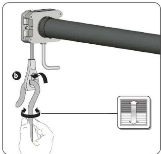

ACHTUNG
natural_image
Mechanical assembly diagram showing a lever and bracket assembly (no text or symbols visible)
Operating and Assembly Manual for RADEMACHER Tubular Motors ....16
EN Translation of the original German manual
natural_image
Illustration of six cylindrical mechanical components with metal pins, arranged in descending order (no text or symbols visible)Bitte notieren: / Please note: / Aub noteren: / Prière de noter / Si prega di indicare: / Tenga en cuenta: Montageort: / Site of Installation: / Montageplaats: / Lieu de montage: / Luogo di montaggio: / Lugar de montaje:
Seriennummer / Serial number / Serienummer / Número de serie / Numero di serie / Número de série
Figures....2
Overall View....17
These instructions....17
Key to Symbols 17
Safety instructions....18
Correct Usage / Operational Conditions....19
Improper use 19
Required expert knowledge of the installer....19
Important installation instructions....20
Installing the tubular motor....21
Installing the bearings....21
Determine the length of the winding shaft 21
Assembly / disassembly of adapters and driver....21
Slide the tubular motor into the winding shaft 22
Preparatory work when using precision tubes....22
Inserting the roller capsule 23
Installing the motor in the bearings 23
Safety instructions for electrical connection 24
Electrical connection 24
Controlling a drive with a single-pole roller blind switch....24
Adjusting the end stops 25
What to do if... ? 27
Technical specifications ....28
Simplified EU declaration of conformity 28
Accessories 29
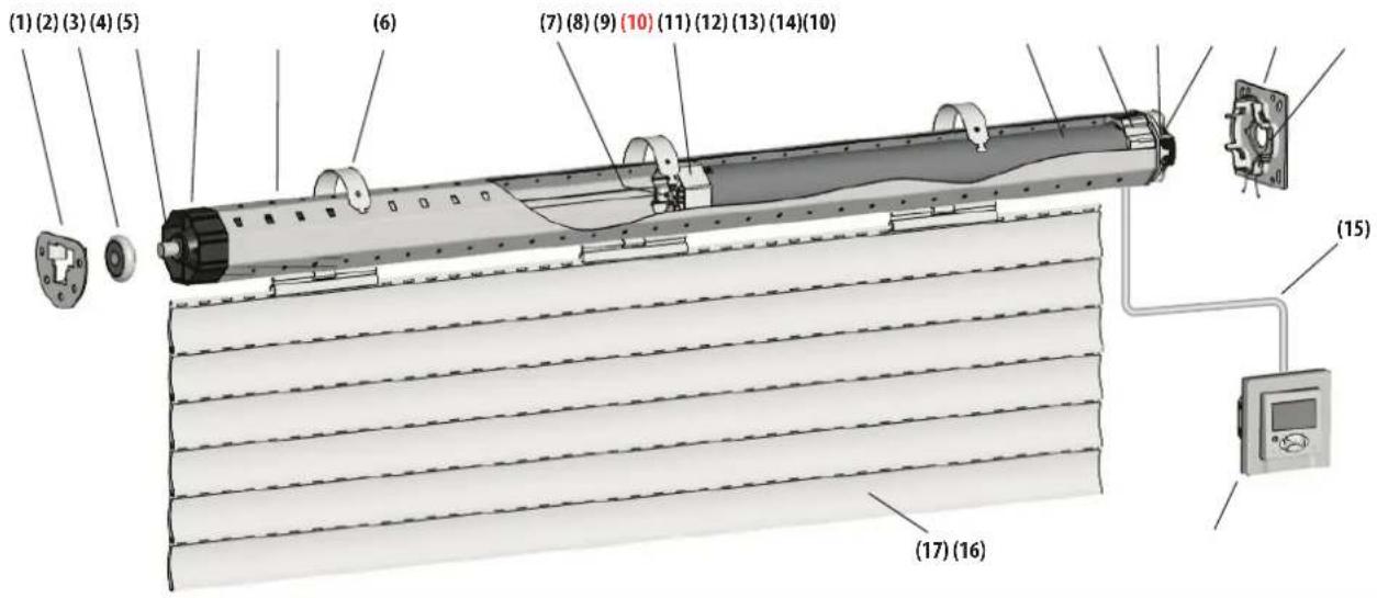
Overall View (Figure 11)
(1) Counter bearing
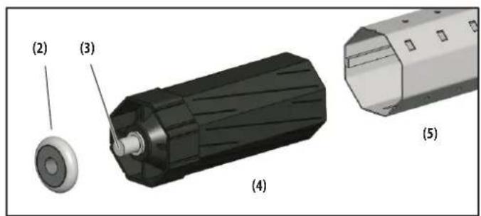
(2) Ball bearing
(3) Axle pin on the roller capsule
(4) Roller capsule
(5) Winding shaft
(6) Tie
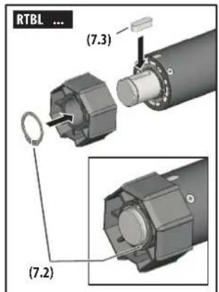
(7.1) Securing clip (Small/Medium)
(7.2) Securing ring (Large)
(7.3) Feather key (Large)
(8) Driver
(9) Tubular motor
(10) Adapter
(11) 2 Adjustment screws
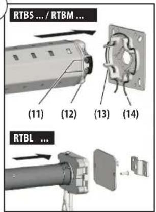
(12) Drive head
(13) Drive bearing
(14) Bracket
(15) Motor cable
(16) Optionally available: Controller (e.g. Troll C50)
(17) Roller shutter curtain
(18) Limit ring
(19) Gearbox output shaft
(20) Hanging brackets
After unpacking, compare:
◆the package contents with the information on the scope of delivery in the package.
◆the motor model with the corresponding information on the rating plate.
These instructions...

◆...describe the installation, electrical connection, and operation of RADEMACHER Tubular Motors of the series RolloTube Basis.
◆Before you begin, please read this manual through completely and follow all the safety instructions and assembly instructions.
◆This manual forms a component of the product. Please store the manual in an easily accessible place.
When passing the tubular motor on to any future owners, this manual must be passed on as well.
◆Damage resulting from non-compliance with these instructions and safety instructions will void the warranty. We assume no liability for any consequential damage.
Key to Symbols

Danger of fatal electric shock
This symbol warns of hazards when working with electrical connections, components, etc. It requires safety measures to protect the health and life of the affected person.

This concerns your safety.
Please pay particular attention and carefully follow all instructions marked with this symbol.

This symbol warns of malpractices that can result in personal injury or property damage.
NOTE/IMPORTANT/CAUTION
This is to draw your attention to information that is important for, trouble-free operation.

For any work on electrical systems, there is a risk to life due to electrocution.
◆Only a certified electrician may connect the tubular motor to the power connection, or do any work on electrical systems, and only in accordance with the connection diagram in these instructions (see page 24).
◆Perform any installation and connection work with the power disconnected.
◆The drive must be disconnected from its power source during the maintenance and replacement of parts.

Risk of fatal electric shock when installed incorrectly in damp rooms.
For use in damp locations, take particular note of DIN VDE 0100, Part 701 and 702. These regulations contain mandatory protection measures.

The use of defective equipment can lead to personal injury and damage to property (electric shocks, short circuiting).
◆Never use defective or damaged devices.
◆Check the drive and power cord for intactness.
◆Please contact our Service Group (see last page) if you find damage to the device.

According to the standard DIN EN 13659, care must be taken that the sliding conditions stipulated in EN 12045 for the hangings are adhered to.
When unrolled, the movement must be at least 40 mm at the lower edge with an upward force of 150 N. Particular care must be taken here to ensure that the outward running speed of the hanging is less than 0.15 m/s over the last 0.4 m of travel.

There is also a risk of fatal injury from crushing resulting from uncontrolled starting of the drive.
Never attempt to manually stop the motor /shutters in the event of uncontrolled movement. In such cases, switch off all power to the drive and take appropriate safety precautions to prevent unintentional switching on. Arrange to have the system checked by a specialist engineer.

Exceeding the maximum permissible running time (KB = transient operation) may overload the tubular motor.
◆The maximum permissible running time for a cycle may not be exceeded when the equipment is in operation. For this reason, the tubular motor has a running time limit (KB = transient operation) of four minutes.
◆ If the running time limit is triggered, then the tubular motor must be left for at least 20 minutes to cool down.

Incorrect use leads to an increased risk of injury.
◆Train all personnel to safely use the tubular motor.
◆Do not allow children to play with the fixed controllers and keep remote controls away from children.
◆Cleaning and user maintenance may not be carried out by children without supervision.
For roller shutters:
◆Watch the moving roller shutter during operation and keep other people away from the area until the movement has been completed.
◆Carry out all cleaning work on the roller shutter whilst the device is disconnected from the mains power.
For awning structures that can be operated outside your range of vision:
◆The awning may not be operated if work is being carried out nearby (e.g. windows being cleaned).
For automatically operated awnings:
◆Disconnect the awning from the power supply if work is being carried out nearby.

A lack of maintenance can lead to personal injury through damage to your tubular motor and roller shutter or awning system:
◆Please check all of your roller shutter system components regularly for damage.
◆Check regularly that the roller shutter system is functioning correctly.
◆ The shutters must not be damaged.
◆ Damaged components should be exchanged by a specialist roller shutter firm.
With awning systems:
◆Please inspect the awning regularly for defective balance and damage to cables and springs.
◆Damaged awnings must only be repaired by specialists.

Contact with the drive housing can cause burns.
◆The tubular motor gets hot during operation. Allow the motor to cool down prior to undertaking any further work on the motor.
◆Never touch the hot drive housing.
Use the tubular motors only to open and close roller blinds and awnings.

The use of the wrong tubular motors or components can lead to property damage.

◆The motor cable must be run inside the empty tube, in compliance with the local electrical codes, to the junction box.
For motor types with PVC connecting cable (see page 28, Technical data), the connecting cable is to be protected by a suitable, earthed empty tube if used outside.
◆Use only original components and accessories from the manufacturer.
◆Only use tubular motors which correspond to the local conditions in terms of their power. Incorrectly dimensioned tubular motors can lead to damage:
An insufficiently dimensioned tubular motor can be damaged due to overloading.
An excessively dimensioned tubular motor can, for example, cause damage to the roller shut-ter or roller shutter box in self-learning mode.
◆Consult a specialist dealer when selecting a tubular motor and observe the corresponding tractive force specifications on our website: www.rademacher.de.
Operational Conditions
◆For the electrical connection, a 230 V/50 Hz power drop must be continuously available at the installation site, with a disconnect device (cut-out) provided by the customer.
◆The roller shutter must run up and down smoothly. It should not jam.

Improper use
Using the tubular motors for purposes other than previously mentioned is impermissible.

Never use the tubular motor in systems with increased safety-relevant requirements or where there is an increased risk of accidents.
◆Such applications require additional safety equipment. Observe the respective statutory regulations for the installation of such systems.

Never use the tubular motor in continuous operation. Doing so will cause serious damage.

Never use the tubular motor for shutters with openings of ≥ 50 mm in diameter.

Required expert knowledge of the installer
The installation, electrical connection and maintenance must be carried out by a qualified person with appropriate training or by a specialist roller shutter firm in accordance with the instructions in this manual.

IMPORTANT
◆Please compare the voltage/frequency specifications on the type plate with those of your local power supply network before installation.
◆Disassemble or deactivate all cables and equipment that will not be needed for operation before installing the tubular motor.
The moving parts of drives that are operated at less than 2.5 m height from the floor must be protected.
If the tubular motor is controlled with a preset OFF switch this switch must be fitted within view of the tubular motor, at a minimum height of 1.5 m and away from moving parts.
◆The roller shutter box cover must be easily accessible and removable.
◆Never dismantle the stoppers from the final roller shutter slat.

Installing the tubular motor at an angle can cause the tubular motor or roller shutter to be damaged. For example, a roller shutter wound at an angle can block the drive and cause damage.
◆Always ensure that the tubular motors and bearings are mounted horizontally.
◆ Please ensure that the winding shaft (5) and the roller shutter (17) can move down easily and freely after installation is complete.
◆ The roller shutter (17) may not run over the bearing, the roller capsule (4) or the drive head (12) during operation.
◆ Ensure that the winding shaft (5) and the rigid shaft connectors (6) do not touch the drive (9). They may not rub against the tubular motor (9) during operation.

For automatically operated awnings:
◆Awnings must be fitted in such a way that there is a minimum distance of 0.4 m between the awning and objects in its immediate proximity when it is fully extended.
◆The lowest point of any awning system must not be less than 1.8 m high.

Incorrectly dimensioned drives and counter bearings can cause the roller shutter system to be damaged.
Only use original bearings supplied by the manufacturer. Thirdparty drives and counter bearings must be selected in accordance with the torque specifications of the respective tubular motors.

Risk of injury in the event of incorrect installation (impact injuries and contusions).
◆The motor can eject from the drive bearing in the event of incorrect installation/fastening. Fasten the tubular motor with the securing devices provided.

Mortal danger in the event of operation without configured end points.
◆The end points must be configured in order to ensure safe operation. In order to do so, please refer to the corresponding chapter in this manual provided on page 25.
NOTE
The following installation instruction apply to standard installation situations for RADEMACHER tubular motors and accessories.
The drive head (12) of the motor can be installed on the right or left side of the roller blind box. Installation on the right side is shown in these instructions.

Installing the bearings (Figure 2)
- First, determine the position of the drive (13) and counter bearings (1) in the roller shutter curtain.
Wind the roller blind shield completely onto the winding shaft, and measure the diameter D. See Figure ② for determining the position of the centre of the bearing on the guide track.
IMPORTANT
When installed, the wound-up roller blind must run vertically in the guide track on the window.
- Mount the bearing, depending on the type of bearing and the building situation.
Assemble the drive bearing (13) such that the adjustment screws (11) will be accessible later, and the motor cable can be run without kinking.

Take care that the bearings are level when installed. A roller blind that is crooked when wound up can jam and destroy the drive.

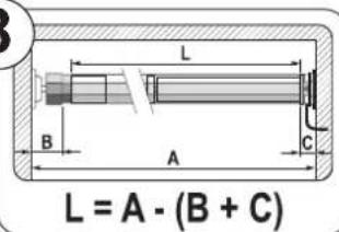
Determine the length of the winding shaft (Figure ⑧)
- Measure the distance from the drive (13) to the counter bearing (1), as shown.
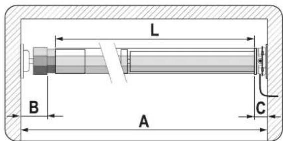
- Measure the roller blind box and determine the shaft length (L) needed.
Length of the winding shaft: L = A - (B + C)
- Cut off the winding shaft (5) to the required dimension.
Saw off the shaft squarely with a metal saw to the correct dimension. Deburr the shaft, inside and outside, with a file.
B = Counter bearing / Roller capsule
C = Drive bearing / Motor

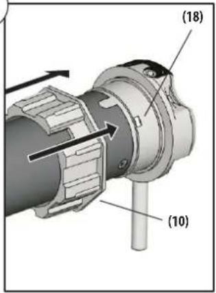
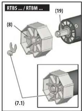
Assembly / disassembly of adapters and driver (Figure ①)
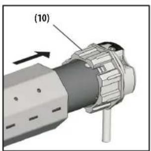
- Assembling the adapter (10)
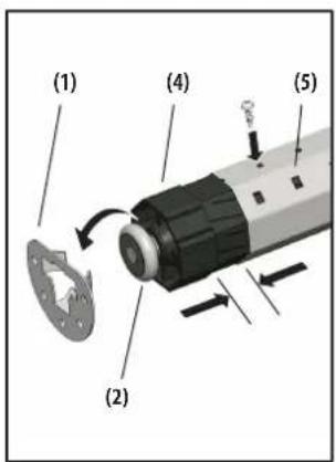
Slide the adapter (10) over the limit ring (18) on the drive head until it engages. Make sure the groove in the adapter (10) is correctly positioned.
- Disassembling the adapter (10)
Press down on both retaining springs on the limit ring (18) and pull the adapter (10) off of the limit ring (18).
- Assembling the driver (8)
Slide the driver (8) onto the axle (19) to the stop and secure it with the included securing clip (7).
- Disassembling the driver (8)
Remove the securing clip (7) from the axle (19) and disassemble the driver (8).

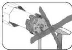
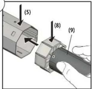
Never strike the motor (9) violently to insert it in the winding shaft (5).
This will destroy it.
- First slide the driver (8) into the 1. winding shaft (5).
IMPORTANT
For winding shaft with interior seams, the motor (9) must have sufficient clearance.
- Next, press the winding shaft (5) completely onto the adapter (10).
IMPORTANT
Take care that the adapter (10) does not slide off of the limit ring (18) on the drive head (12) during assembly, or a malfunction will occur; see page 27.
For Small / Medium only
Preparatory work when using precision tubes (Figures 5a - 5f)
5.a
natural_image
Technical illustration of a cylindrical mechanical part with a ruler and pointer, no text or symbols present5.b
5.c
5.d
natural_image
Cross-sectional diagram of a cylindrical mechanical component with internal features and arrows indicating direction (no text or symbols)-
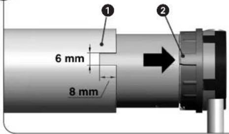
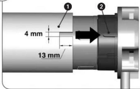
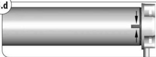
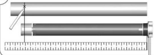
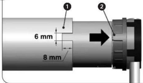
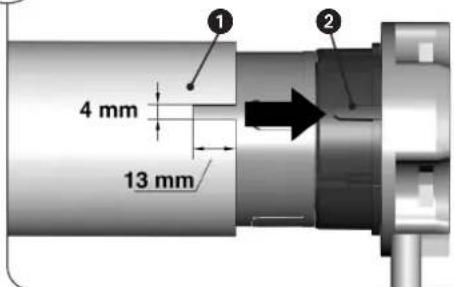
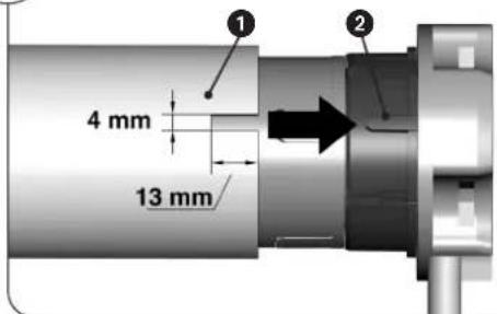
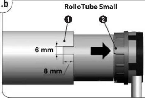
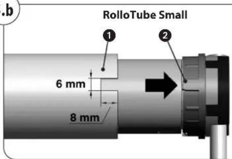
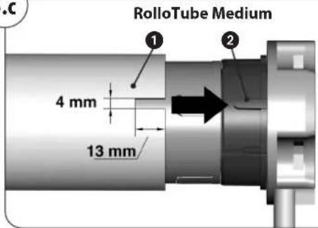
Measure the distance between the adapter and the rear third of the driver and mark this distance on the precision tube.
-
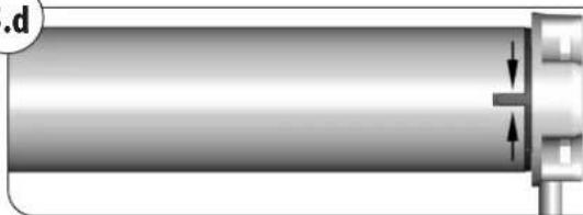
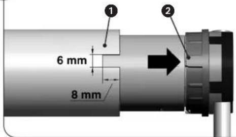
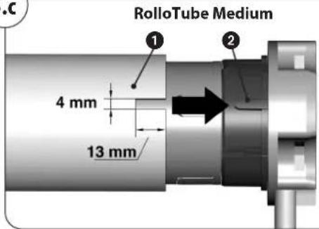
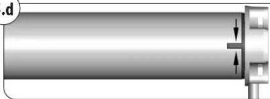
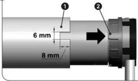
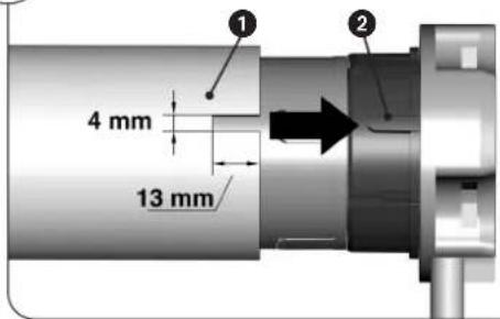
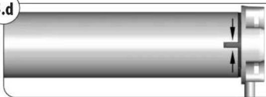
Saw a notch ① at the end of the precision tube so that the raised part ② of the adapter can be pushed fully into the tube.
NOTE
There must be no play between the notch ① and the raised part ②.
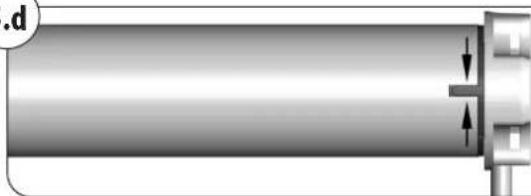
◆ The dimensions of the notch ① depend on the type of tubular motor, see figures.
natural_image
Mechanical assembly diagram showing a pipe being welded with clamps, no text or symbols present5.f
natural_image
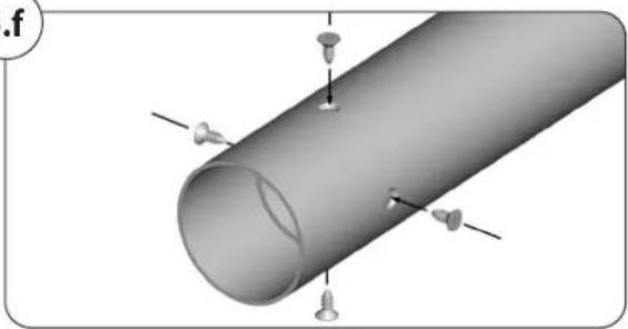
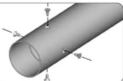
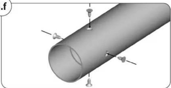
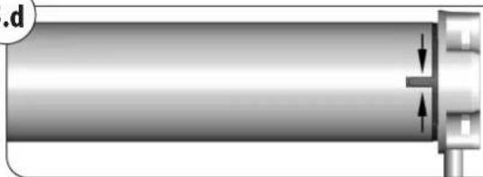
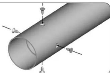
3D rendering of a cylindrical pipe with multiple screw fasteners inserted (no text or symbols visible)- Mark four fixing holes and drill these through the precision tube into the driver.

CAUTION
◆Never drill deeper than 10 mm into the driver.
◆Never drill close to the drive as this will cause it to malfunction.
- Screw fix or rivet the precision tube to the driver using self-tapping screws or four blind rivets.

Inserting the roller capsule (Figure 5)
- Slide the roller capsule (4) into the winding shaft (5), then place the ball bearing (2) on the axle pin (3).

Installing the motor in the bearings (Figure 6)
1. Drive bearing (13) - as a click bearing
Press the drive head (12) lightly into the drive bearing (13) until it engages.
NOTE
The adjustment screws (11) must be accessible.
The tubular motors can be installed in the click bearing (13) in 4 positions. By spreading the bracket (14), you can remove the motors from the click bearing (13) again at any time.
Drive bearing (13) - all other bearing variants
Place the drive head (12) on the drive bearing and secure it appropriately, such as with a splint.
2. Counter bearing (1)
Insert the other end of the winding shaft (5) with the ball bearing (2) into the counter bearing (1).
If you are using a different drive bearing than the RADEMACHER click bearing, you may now need to secure the drive with another splint.
3. Correct for slight dimensional accuracies by sliding the roller capsule (4) in or out.
IMPORTANT
◆ Secure the roller capsule (4) with a screw afterward.
◆ The roller capsule (4) must have at least 2/3 of its length inserted into the winding shaft (5).

For any work on electrical systems, there is a risk to life due to electrocution.
Only a certified electrician may connect the tubular motor to the power connection, or do any work on electrical systems, and only in accordance with the connection diagram in these instructions.
◆Disconnect the feed from the grid on all poles, and secure it against unintended connection.
◆Test the system for zero voltage.
◆Perform any installation and connection work only with the power disconnected.

Damaged cables present a short circuit hazard.
◆Run all cables in the roller blind box, such that they cannot be damaged by moving parts.
◆Only connect the mains cable for this drive to a similar type of cable. If in doubt, contact our Customer Service department.

For fixed installation devices...
...A disconnect must be present for each phase on the installation side, according to DIN VDE 0700. Switches with a contact opening width of at least 3 mm (e.g., circuit breakers, fuses, or residual current devices).

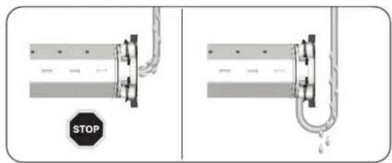
Short circuit hazard due to water if cables are improperly routed.
Never route the motor cable (15) directly vertically, or water may run down the cable into the motor and destroy it. Route the cable in a loop. The loop ensures that water running down the cable is collected at the lowest point and drips from there.

Electrical connection (Figure Ⓟ)
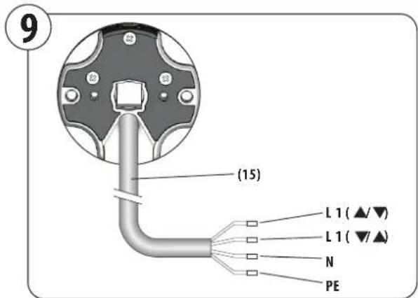
1. Run the motor cable (15), after mounting the motor, in the junction box or switch box provided for it.
Color codes for motor conductors (15)
L1 = Rotational direction 1 (black)
L1 = Rotational direction 2 (brown)
N = Neutral line (blue)
PE = Ground (green/yellow)

Controlling a drive with a single-pole roller blind switch
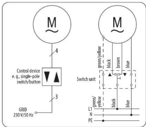
Installation layout and connection diagram for mounting on the right side.
1.

NOTE
Perform a test run on the motor first, without the roller shutter curtain in place. Let the motor run (using a time switch or a switch) in the down (▼) direction until it shuts off by itself. Please ensure that this is the correct downward direction, or down (▼) for your roller blind.
If the roller blind motor is running in the wrong direction (motor running direction does not match the switch positions for up (▲) and down (▼)), switch the brown and black conductors in the junction box or switch box.
Now run the motor further in the down (▼) direction until it reaches the lower limit stop.
2.
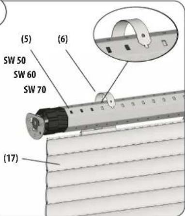
Assembly of the roller shutter curtain (figure ⑦ ⑧ Install the roller shutter curtain (17) on the winding shaft (5) using ties (6) (accessories).

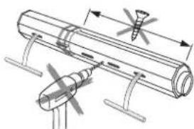
Never drill or screw into the area of the drive to mount the roller blind.
IMPORTANT
The limit stops work only if the motor is installed in the winding shaft.
natural_image
Technical diagram of a mechanical assembly with no visible text or symbolsa) Slide the tie (6) onto the topmost segment of the roller shutter curtain (17).
b) Place an tie (6) in the rectangular holes in the winding shaft (5) every 40 cm.
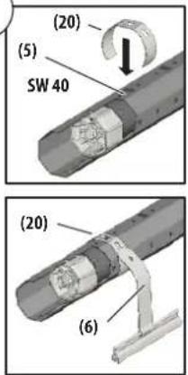
c) For SW 40 winding shafts (with outer seams), use hanging brackets (20) to assemble the tie (6); see Figure 8
3.
IMPORTANT
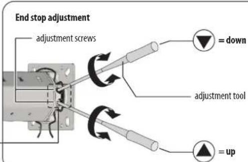
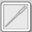
The end stops for the top and bottom are adjusted by means of 2 adjustment screws. Use the included adjustment tool to turn the screws.
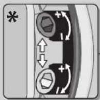

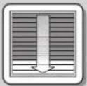
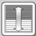
= extension of each route

= shortening each route
For right or left-hand installation: The lower end stop is set using the adjustment screw on the arrow pointing upwards. The upper end stop is set using the adjustment screw on the arrow pointing downwards.
◆Turning in the + (plus) direction extends the route.
◆Turning the opposite way causes it to shorten.
* The actual plus and minus directions may vary by model.
Check the printing on the motor head.

Upper end stop
Run the motor in the up (▲) direction. Carefully turn the corresponding adjustment screw, using the enclosed adjustment tool, in the minus (-) direction, until the motor switches off. Leave the time switch or the switch in the «up» position, and carefully turn the appropriate adjustment screw in the plus (+) direction, using the included adjustment tool, until the motor has reached the desired end stop.
Safety instructions: Temperature differences (winter - summer) may occur on the roller shutter curtain. Therefore, adjust the end position for up (▲to have 2-3 cm of «air».
Lower end stop (readjustment)
Run the motor in the down (▼) direction. Carefully turn the corresponding adjustment screw, using the enclosed adjustment tool, in the minus (-) direction, until the motor switches off. Leave the time switch or the switch in the «up» position, and carefully turn the appropriate adjustment screw in the plus (+) direction, using the included adjustment tool, until the motor has reached the desired end stop.
Test run / Changing the end stops
Check your settings, and run the roller blind in both directions until the end stops switch off the motor.

Thermal protection
The tubular motors are designed for brief operation (approx. 4 min).
Exceeding this time, or frequent switching back and forth, leads to heat build-up. In this case, let the motor cool for about 20 minutes.
Changing the end stops
Run the roller blind back to the centre position, and start again from the beginning. See Figure end stop adjustment (Pos. 3) on page 25.
The drive does not raise or lower the roller blind, starts too slowly or makes loud noises.
Possible cause 1:
◆Connections are incorrect.
Solution 1:
◆Check connections.
Possible cause 2:
◆Incorrect installation or overload.
Solution 2:
◆Check the installation and roller blind load.
...the roller blind stops during raising or lowering?
Possible cause 1:
◆The end stop was reached.
Solution 1:
◆Set the end stops again, according to the instructions.
Possible cause 2:
◆Running time exceeded (4 min.).
Solution 2:
◆Let the tubular motor cool for about 20 minutes.
...the motor does not run?
Possible cause:
◆Power supply is missing.
Solution:
◆Use a voltmeter to check whether the supply voltage (230 V) is present, and check the wiring.
◆Take note in particular of information about non-permissible types of connections.
◆Check the installation.
...the rotary direction is wrong?
Possible cause:
◆Control lines are reversed.
Solution:
◆Disconnect the supply line from the power, and swap the black and brown conductors of the motor cable at the controller.
...The tubular motor does not stop for adjustments or test runs?
Possible cause 1:
◆ The adapter (10) may have slipped off of the limit ring (18) on the drive head (12).
Solution 1:
◆ Check whether the adapter (10) is fully seated in front of the drive head (12) and is completely inserted in the winding shaft (5).
◆ Slide the adapter (10) so that it contacts the front of the drive head (12) again, and slide the winding shaft (5) completely onto the adapter (10); see Figure 3. Readjust the end stops if needed; see page 25.
Possible cause 2:
◆Roller capsule not secured, or roller blind shaft too short.
Solution 2:
◆Secure the roller capsule, or use a roller blind shaft that fits.
...The tubular motor stops between the two end stops during normal operation?
Possible cause:
◆The thermal protection is engaged.
Solution:
◆Let the motor cool for about 20 minutes.
...the roller blind stops during upward travel?
Possible cause:
◆Ice on the roller blind or obstacle in the running track.
Solution:
◆Remove the ice or obstacle.
◆Move the roller blind downward to free it.
| Motor series Small Medium | ||||||||||||
| Model: HK HK HK HK = with a hard crank function, | ||||||||||||
| 6 10 10 | 20 20 30 | 30 40 40 50 | 50 [Nm] | Nominal torque | ||||||||
| 28 16 | 16 16 16 | 16 16 16 12 | 12 [rpm] | Idle speed | ||||||||
| 230 | 230 | 230 | 230 | 230 | 230 | 230 | 230 | 230 | 230 | 230 | [V] | |
| 50 50 | 50 50 50 | 50 50 50 | 50 [Hz] | Frequency | ||||||||
| 121 | 121 | 112 | 145 | 145 | 191 | 191 | 198 | 198 | 205 | 205 | [W] | |
| 0,53 | 0,53 | 0,49 | 0,64 | 0,64 | 0,83 | 0,83 | 0,86 | 0,86 | 0,89 | 0,89 | [A] | |
| 4 | 4 | 4 | 4 | 4 | 4 | 4 | 4 | 4 | 4 | 4 | [Min.] | |
| 4 | 4 | 4 | 4 | 4 | 4 | 4 | 4 | 4 | 4 | 4 | ||
| 0,75 | 0,75 | 0,75 | 0,75 | 0,75 | 0,75 | 0,75 | 0,75 | 0,75 | 0,75 | 0,75 | [mm2] | |
| 2,5 | 2,5 | 2,5 | 2,5 | 2,5 | 2,5 | 2,5 | 2,5 | 2,5 | 2,5 | 2,5 | [m] | |
| 30 30 | 22 22 22 | 22 22 22 | 22 [R] | Limit switch range: (number | ||||||||
| H | H | H | H | H | H | H | H | H | H | H | ||
| I | I | I | I | I | I | I | I | I | I | I | ||
| IP 44 | IP 44 | IP 44 | IP 44 | IP 44 | IP 44 | IP 44 | IP 44 | IP 44 | IP 44 | IP 44 | △ | |
| PVC | PVC | PVC | PVC | rubber | PVC | rubber | PVC | rubber | PVC | rubber | ||
| 472 | 472 | 474 | 474 | 574 | 544 | 624 | 544 | 624 | 544 | 624 | [mm] | |
| 35 35 | 45 45 45 | 45 45 45 | 45 [mm] | Tube diameter | ||||||||
| ≤70 | ≤70 | ≤70 | ≤70 | ≤70 | ≤70 | ≤70 | ≤70 | ≤70 | ≤70 | ≤70 | [dB(A)] | |
| see „Accessories“, page 29 |
| Nominal voltage |
| Nominal power |
| Current draw |
| Duty cycle (KB) |
| Number of conductors |
| Conductor sectional area |
| Cable length (standard) |
| of revolutions) |
| Insulation class |
| Protection class |
| Type of protection per VDE 700 |
| Type of conductor |
| Motor length, without bearings |
| Noise pressure level (LpA) |
| Motor series | Medium Short Version | Large | ||||||||||
| Model: HK HK HK = with a hard crank function, | ||||||||||||
| 10 | 20 | 60 | 60 | 80 | 80 | 100 | 100 | 120 | 120 | [Nm] | ||
| 16 | 16 | 16 | 16 | 16 | 16 | 12 | 12 | 9 | 9 | [rpm] | ||
| 230 | 230 | 230 | 230 | 230 | 230 | 230 | 230 | 230 | 230 | [V] | ||
| 50 50 | 50 50 50 50 50 | 50 50 50 [Hz] | Frequency | |||||||||
| 112 | 145 | 272 | 272 | 298 | 298 | 305 | 305 | 305 | 305 | [W] | ||
| 0,49 | 0,64 | 1,26 | 1,26 | 1,34 | 1,34 | 1,36 | 1,36 | 1,36 | 1,36 | [A] | ||
| 4 | 4 | 4 | 4 | 4 | 4 | 4 | 4 | 4 | 4 | [Min.] | ||
| 4 | 4 | 4 | 4 | 4 | 4 | 4 | 4 | 4 | 4 | |||
| 0,75 | 0,75 | 0,75 | 0,75 | 0,75 | 0,75 | 0,75 | 0,75 | 0,75 | 0,75 | [mm^2] | ||
| 2,5 | 2,5 | 2,5 | 2,5 | 2,5 | 2,5 | 2,5 | 2,5 | 2,5 | 2,5 | [m] | ||
| 17 | 17 | 22 | 22 | 22 | 22 | 22 | 22 | 22 | 22 | [R] | ||
| H | H | H | H | H | H | H | H | H | H | |||
| I | I | I | I | I | I | I | I | I | I | |||
| IP 44 | IP 44 | IP 44 | IP 44 | IP 44 | IP 44 | IP 44 | IP 44 | IP 44 | IP 44 | ▲ | ||
| PVC | PVC | rubber | rubber | rubber | rubber | rubber | rubber | rubber | rubber | |||
| 365 | 380 | 658 | 658 | 658 | 658 | 658 | 658 | 658 | 658 | [mm] | ||
| 45 45 | 60 60 60 60 60 | 60 60 60 [mm] | Tube diameter | |||||||||
| ≤ 70 | ≤ 70 | ≤ 70 | ≤ 70 | ≤ 70 | ≤ 70 | ≤ 70 | ≤ 70 | ≤ 70 | ≤ 70 | [dB(A)] | ||
| see „Accessories“, page 29 |
| Nominal torque |
| Idle speed |
| Nominal voltage |
| Nominal power |
| Current draw |
| Duty cycle (KB) |
| Number of conductors |
| Conductor sectional area |
| Cable length (standard) |
| Limit switch range: (number of revolutions) |
| Insulation class |
| Protection class |
| Type of protection per VDE 700 |
| Type of conductor |
| Motor length, without bearings |
| Noise pressure level (LpA) |
Simplified EU declaration of conformity

RADEMACHER Geräte-Elektronik GmbH hereby declares that the tubular motors in the RolloTube Basic Small, Medium (short version) and Large series (item no.: 2140 06 96 / 2140 10 96 / 2160 10 96 / 2160 20 96 / 2160 30 96 / 2160 40 96 / 2160 50 96 / 2160 30 98 / 2160 40 98 / 2160 50 98 / 2170 60 96 / 2170 70 96 / 2170 80 96 / 2170 91 96 / 2170 92 96 / 2170 60 98 / 2170 80 98 / 2170 91 98 / 2170 92 98 / 2160 10 26 / 2160 20 26) comply with the Directives 2006/42/EC (Machinery Directive) and 2014/30/EU (EMC Directive).
The full text of the EU declaration of conformity is included with the product and is kept on file by the manufacturer.
46414 Rhede (Germany)
Warranty terms and conditions
Information about the warranty conditions of our products can be found on our homepage.
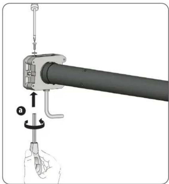
For models in the RolloTube Basic series (medium/large) with a manual override function, it is possible to operate the tubular motor with a hand crank in the event of a power failure or malfunctions.
Versions with a hand crank function (HK)
See page 28, Technical specifications.
Hand crank and hand crank eyelet
The hand crank and hand crank eyelet are accessories and not included in the scope of delivery.
Item number:
Hand crank: 96000003
Hand crank eyelet: 96000002 (150 mm) 96000034 (270 mm)
natural_image
Mechanical assembly diagram showing a lever mechanism with a rotating shaft and adjustment tool (no text or symbols)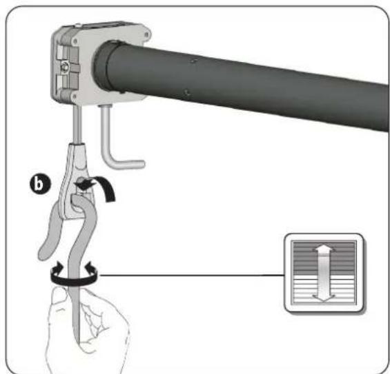

CAUTION
It is essential to disconnect the motor from the mains power before using the hand crank!
◆ The hand crank must only be used in the event of a power failure; also make sure that the end positions are not overrun.
◆ People must be kept away from the system during manual operation.
The hand crank must be removed from the system again immediately after using it due to the risk of injury or property damage.
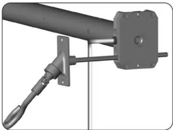
Hand crank and articulated hand crank eyelet
You can alternatively use a fixed articulated hand crank eyelet for installation in roller shutter boxes. The articulated hand crank eyelet is an accessory and not included in the scope of delivery.
Item number:
Hand crank: 96000003
Articulated hand crank eyelet: 90000085
natural_image
Mechanical assembly diagram showing a lever and bracket assembly (no text or symbols visible)
See the short accessory guide for details about the installation of the articulated hand crank eyelet.
EN Operating and Assembly Manual for RADEMACHER Tubular Motors 16 Translation of the original German manual
natural_image
Illustration of multiple cylindrical mechanical components with mounting flanges and housing (no text or symbols)Bitte notieren: / Please note: / Aub noteren: / Prière de noter / Si prega di indicare: / Tenga en cuenta: Montageort: / Site of Installation: / Montageplaats: / Lieu de montage: / Luogo di montaggio: / Lugar de montaje:
Seriennummer / Serial number / Serienummer / Número de serie / Numero di serie / Número de série
Afbeeldingen 2
Overzicht 31
(7.1) Borgclip (Small/Medium)
(7.2) Borgring (Large)
(7.3) Pasveer (Large)
(8) Meenemer
(9) Buismotor
(10) Adapter
(11) 2 Stelschroeven
natural_image
Technical illustration of a cylindrical mechanical part with a ruler below, showing alignment and measurement (no text or symbols)5.b
5.c
5.d
natural_image
Cross-sectional diagram of a cylindrical mechanical component with internal features and arrows indicating direction (no text or symbols)natural_image
3D diagram of a pipe with screw fasteners and a circular label '5.f' (no text or symbols on the pipe itself)natural_image
Two diagrams showing pipe connection with a stop sign, no text or symbols present
natural_image
Technical line drawing of a mechanical assembly with no visible text or symbols◆De thermobeveiliging is ingeschakeld.
Oplossing:
natural_image
Mechanical assembly diagram showing a lever mechanism with a hand holding a tool, no text or symbols present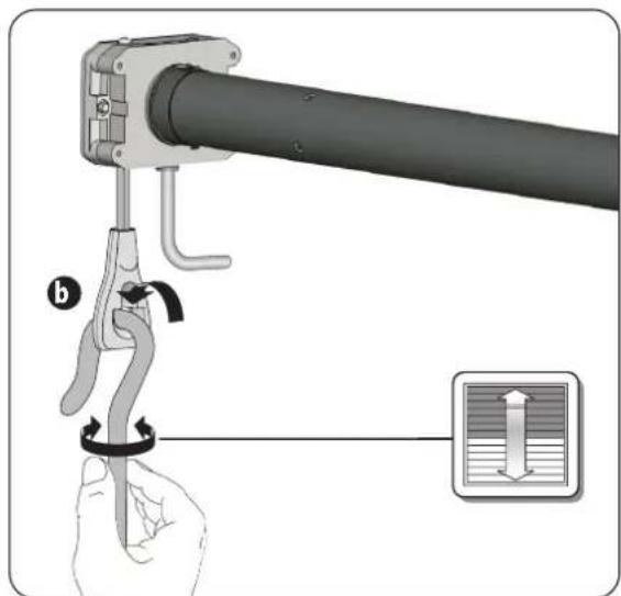

LET OP
natural_image
Mechanical assembly diagram showing a lever and bracket assembly (no text or symbols visible)
EN Operating and Assembly Manual for RADEMACHER Tubular Motors 16 Translation of the original German manual
natural_image
Illustration of six cylindrical mechanical components with metal fittings, arranged in two rows (no text or symbols visible)Bitte notieren: / Please note: / Aub noteren: / Prière de noter / Si prega di indicare: / Tenga en cuenta: Montageort: / Site of Installation: / Montageplaats: / Lieu de montage: / Luogo di montaggio: / Lugar de montaje:
Seriennummer / Serial number / Serienummer / Número de serie / Numero di serie / Número de série
Illustrations 2
Vue d'ensemble 45
Ce mode d'emploi 45
natural_image
Technical illustration of a cylindrical mechanical component with a ruler below, showing alignment and measurement (no text or symbols)5.b
5.c
5.d
natural_image
Cross-sectional diagram of a cylindrical mechanical component with internal features and dimension arrows (no text or symbols)natural_image
Mechanical assembly diagram showing a pipe being welded with clamps, no text or symbols present5.f
natural_image
3D rendering of a cylindrical pipe with multiple screw fasteners inserted (no text or symbols)1.
natural_image
Technical diagram of a mechanical assembly with no visible text or symbolsnatural_image
Mechanical assembly diagram showing a lever mechanism with a hand holding a tool, no text or symbols present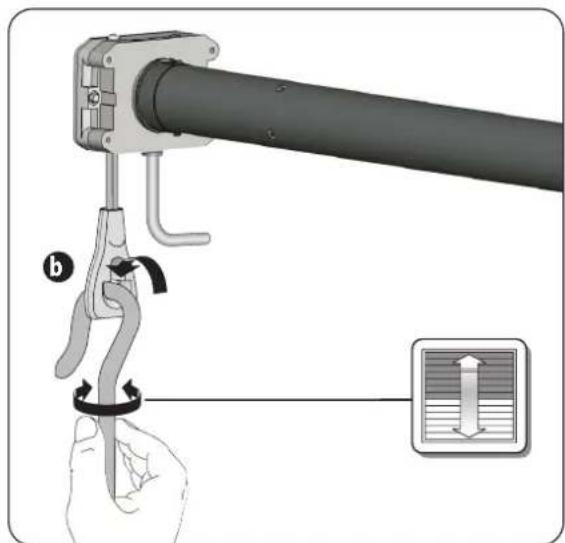

PRUDENCE
natural_image
Mechanical assembly diagram showing a lever and bracket assembly (no text or symbols visible)
natural_image
Illustration of six cylindrical mechanical components with metal fittings, arranged in descending order (no text or symbols visible)Bitte notieren: / Please note: / Aub noteren: / Prière de noter / Si prega di indicare: / Tenga en cuenta: Montageort: / Site of Installation: / Montageplaats: / Lieu de montage: / Luogo di montaggio: / Lugar de montaje:
Seriennummer / Serial number / Serienummer / Número de serie / Numero di serie / Número de série
Figure 2
Vista generale 59
(7.3) Chiavetta (Large)
(8) Trascinatore
(9) Motore tubolare
(10) Adattatore
natural_image
Technical illustration of a cylindrical mechanical component with a ruler below, showing alignment and measurement (no text or symbols)5.b
5.c
5.d
natural_image
Cross-sectional diagram of a cylindrical mechanical component with internal features and dimension arrows (no text or symbols)natural_image
3D diagram of a pipe with screw fasteners and a circular label '5.f' (no text or symbols on the pipe itself)1.
natural_image
Technical diagram of a mechanical assembly with no visible text or symbolsnatural_image
Mechanical assembly diagram showing a lever mechanism with a hand holding a tool, no text or symbols present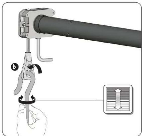

ATTENZIONE
natural_image
Mechanical assembly diagram showing a lever and bracket assembly (no text or symbols visible)
natural_image
Illustration of six cylindrical mechanical components with metal fittings, arranged in a row (no text or symbols visible)Bitte notieren: / Please note: / Aub noteren: / Prière de noter / Si prega di indicare: / Tenga en cuenta: Montageort: / Site of Installation: / Montageplaats: / Lieu de montage: / Luogo di montaggio: / Lugar de montaje:
Seriennummer / Serial number / Serienummer / Número de serie / Numero di serie / Número de série
Figuras 2
natural_image
Technical illustration of a cylindrical mechanical component with a ruler below, showing alignment and measurement (no text or symbols)5.b
5.c
5.d
natural_image
Cross-sectional diagram of a cylindrical mechanical component with internal features and dimension arrows (no text or symbols)natural_image
Mechanical assembly diagram showing a pipe being inserted into a cylindrical component with tool holders (no text or symbols present)5.f
natural_image
3D rendering of a cylindrical pipe with multiple screw fasteners inserted (no text or symbols visible)
1.
natural_image
Technical line drawing of a cylindrical mechanical component with attached components and dimension arrows (no text or symbols)natural_image
Mechanical assembly diagram showing a pipe being inserted into a clamp, with no visible text or symbols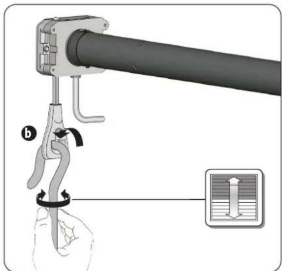
natural_image
Illustration of a hand holding a tool with a spring, showing the process with an inset showing fluid flow (no text or symbols)
ATENCIÓN
natural_image
Mechanical assembly diagram showing a lever and bracket assembly (no text or symbols visible)
- 4.
- ACHTUNG
- Overall View (Figure 11)
- After unpacking, compare:
- These instructions...
- Key to Symbols
- Danger of fatal electric shock
- This concerns your safety.
- This symbol warns of malpractices that can result in personal injury or property damage.
- NOTE/IMPORTANT/CAUTION
- For any work on electrical systems, there is a risk to life due to electrocution.
- Risk of fatal electric shock when installed incorrectly in damp rooms.
- The use of defective equipment can lead to personal injury and damage to property (electric shocks, short circuiting).
- According to the standard DIN EN 13659, care must be taken that the sliding conditions stipulated in EN 12045 for the hangings are adhered to.
- There is also a risk of fatal injury from crushing resulting from uncontrolled starting of the drive.
- Exceeding the maximum permissible running time (KB = transient operation) may overload the tubular motor.
- Incorrect use leads to an increased risk of injury.
- For roller shutters:
- For awning structures that can be operated outside your range of vision:
- For automatically operated awnings:
- A lack of maintenance can lead to personal injury through damage to your tubular motor and roller shutter or awning system:
- With awning systems:
- Contact with the drive housing can cause burns.
- The use of the wrong tubular motors or components can lead to property damage.
- Operational Conditions
- Improper use
- Never use the tubular motor in systems with increased safety-relevant requirements or where there is an increased risk of accidents.
- Required expert knowledge of the installer
- IMPORTANT
- Installing the tubular motor at an angle can cause the tubular motor or roller shutter to be damaged. For example, a roller shutter wound at an angle can block the drive and cause damage.
- Incorrectly dimensioned drives and counter bearings can cause the roller shutter system to be damaged.
- Risk of injury in the event of incorrect installation (impact injuries and contusions).
- Mortal danger in the event of operation without configured end points.
- NOTE
- Installing the bearings (Figure 2)
- Determine the length of the winding shaft (Figure ⑧)
- Assembly / disassembly of adapters and driver (Figure ①)
- For Small / Medium only
- 5.f
- CAUTION
- Inserting the roller capsule (Figure 5)
- Installing the motor in the bearings (Figure 6)
- Drive bearing (13) - as a click bearing
- Drive bearing (13) - all other bearing variants
- Counter bearing (1)
- Correct for slight dimensional accuracies by sliding the roller capsule (4) in or out.
- Damaged cables present a short circuit hazard.
- For fixed installation devices...
- Short circuit hazard due to water if cables are improperly routed.
- Electrical connection (Figure Ⓟ)
- Run the motor cable (15), after mounting the motor, in the junction box or switch box provided for it.
- Color codes for motor conductors (15)
- Controlling a drive with a single-pole roller blind switch
- 1.
- 2.
- 3.
- Upper end stop
- Lower end stop (readjustment)
- Test run / Changing the end stops
- Thermal protection
- Changing the end stops
- Possible cause 1:
- Solution 1:
- Possible cause 2:
- Solution 2:
- Possible cause:
- Solution:
- Simplified EU declaration of conformity
- Warranty terms and conditions
- Versions with a hand crank function (HK)
- Hand crank and hand crank eyelet
- Hand crank and articulated hand crank eyelet
- Oplossing:
- LET OP
- PRUDENCE
- ATTENZIONE
- ATENCIÓN
Brand : RADEMACHER
Model : RolloTube Basis RTBM 40/16Z
Category : Uncategorized