
BEVPMS 120 - Air-conditioner BEKO - Free user manual and instructions
Find the device manual for free BEVPMS 120 BEKO in PDF.


| Product Type | Split Air Conditioner (Cooling & Heating) |
| Model | BEVPMS 120 |
| Refrigerant | R32 (GWP: 675) |
| Cooling Capacity | 11,942 Btu/h (3.5 kW) |
| Heating Capacity | 9,212 Btu/h (2.7 kW) |
| Energy Class Cooling | A++ (EU) |
| Energy Class Heating | A+ (Average) / A+++ (Warmer) |
| SEER | 7.0 (W/W) |
| SCOP | 4.1 (Average) / 5.1 (Warmer) |
| Power Supply | 220-240 V ~ 50 Hz, 1 Ph |
| Cooling Power Input | 728 W |
| Heating Power Input | 1,049 W |
| Indoor Unit Dimensions (WxHxD) | 768 x 299 x 201 mm |
| Outdoor Unit Dimensions (WxHxD) | 780 x 530 x 310 mm |
| Indoor Unit Weight | 8 kg |
| Outdoor Unit Weight | 23 kg |
| Max Pipe Length | 20 m |
| Max Height Difference | 10 m |
| Noise Level Indoor | 53 / 48 / 44 / 42 / 29 dBA (depending on fan speed) |
| Noise Level Outdoor | 62 / 56 / 51 / 49 / 34 dBA |
| Airflow Volume | 650 / 570 / 520 / 470 m³/h (4 speeds) |
| Features | Washable air filter, self-diagnosis, anti-corrosion treatment, emergency operation |
Frequently Asked Questions - BEVPMS 120 BEKO
User questions about BEVPMS 120 BEKO
0 question about this device. Answer the ones you know or ask your own.
Ask a new question about this device
Download the instructions for your Air-conditioner in PDF format for free! Find your manual BEVPMS 120 - BEKO and take your electronic device back in hand. On this page are published all the documents necessary for the use of your device. BEVPMS 120 by BEKO.
USER MANUAL BEVPMS 120 BEKO
natural_image
Simple line icon of a rectangular box with two sparkles above it, no text or symbols present.BEVPMS 090/BEVPMS 091 BIHPM 090/ BIHPM 091
BEVPMS 120/ BEVPMS 121 BIHPM 120/ BIHPM 121
BEVPMS 180/ BEVPMS 181 BIHPM 180/ BIHPM 181
BEVPMS 240/ BEVPMS 241 BIHPM 240/ BIHPM 241
EN - BG - SQ - BS - SR - MK
CONTENTS
ENGLISH 3-56
БЪЛГАРСКИ 57-113
SHQIP 114-167
BOSANSKI 168-221
SRPSKI 222-275
МАКЕДОНСКИ 276-336
Please read this user manual first!
Dear Customer,
Thank you for preferring a Beko product. We hope that you get the best results from your product which has been manufactured with high quality and state-of-the-art technology. Therefore, please read this entire user manual and all other accompanying documents carefully before using the product and keep it as a reference for future use. If you handover the product to someone else, give the user manual as well. Follow all warnings and information in the user manual.
Meanings of the symbols
Following symbols are used in the various section of this manual:

Important information or useful hints about usage.

Warning for hazardous situations with regard to life and property.

Warning to actions that must never perform.
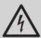
Warning for electric shock.

This symbol shows that information is available such as the operating manual or installation manual.
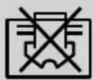
Do not cover it.

This symbol shows that the operation manual should be read carefully.
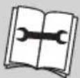
This symbol shows that a service personnel should be handling this equipment with reference to the installation manual.
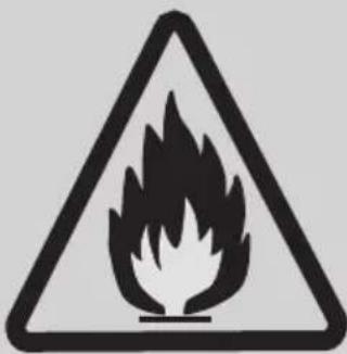
(For R32/ R290 gas type)
This symbol shows that this appliance used a flammable refrigerant. If the refrigerant is leaked and exposed to an external ignition source, there is a risk of fire.
CONTENTS
1 Warning 7
2 Safety precautions 12
3 Notices for usage 21
3.1 The conditions of unit can't normally run 21
3.2 Notes for heating 21
3.3 Notes for turning off 21
3.4 Emergency operation....21
3.5 Airflow direction adjustment 22
3.6 Specific caution 22
4 Names of each part 23
4.1 Indoor unit 23
4.2 Outdoor unit 23
5 Clean and care 25
5.1 Clean the panel 25
5.2 Clean the air filter 25
5.3 Check before using 26
5.4 Maintain after using.... 26
6 Troubleshooting 27
7 Notices for installation 30
7.1 Unpacking Inspection 30
7.2 Safety Principles for Installing Air Conditioner 30
7.3 Requirements for installation position 31
7.4 Installation environment inspection 31
7.5 Requirements of the mounting structure 31
CONTENTS
7.6 Installation guide at the seaside 31
7.7 Electrical Safety Requirements 32
7.8 Requirements for operations at raised height 33
7.9 Grounding Requirements 33
7.10 Others 34
7.11 Packing list 34
8 Installation for indoor unit 35
8.1 Dimension drawing of indoor unit installation 35
8.2 Mounting plate 35
8.3 Wall-through Hole 35
8.4 Route of Pipeline.... 36
8.5 Install the connection pipe 36
8.6 Wrap the Piping 36
8.7 Fixing the Indoor Unit 37
8.8 Interconnection cord installation.... 37
9 Installation for outdoor unit 39
9.1 Dimension drawing of outdoor unit installation.... 39
9.2 Install the connection pipe 39
9.3 Wiring Connection 40
9.4 Wiring diagram 41
9.5 Vacuuming 42
9.6 Outdoor condensation drainage (Heat pump type only). 42
10 Check after installation and test operation 43
10.1 Check after installation 43
10.2 Test operation 43
10.3 Test Operation method: 43
CONTENTS
11 Maintenance Notice 44
11.1 Qualification requirements of maintenance personnel 44
11.2 Inspection of the Site.... 44
11.3 Operating Procedures 44
11.4 Inspection of Cable 46
11.5 Leakage check of R32 refrigerant 46
11.6 Removal and Vacuum Pumping 46
11.7 Procedures of Charging Refrigerants 47
11.8 Scrap and Recovery.... 47
12 European disposal guidelines 49
13 F-gas instruction 50
14 Specifications 51
1 Warning

Note:
FCC and IC related content only applies to models with WiFi function.
FCC WARNING

Warning:
Changes or modifications to this unit not expressly approved by the party responsible for compliance could void the user's authority to operate the equipment.
FCC STATEMENT
This device complies with Part 15 of the FCC Rules. Operation is subject to the following two conditions:
(1) this device may not cause harmful interference, and (2) this device must accept any interference received, including interference that may cause undesired operation.
1 Warning

Note:
This equipment has been tested and found to comply with the limits for a Class B digital device, pursuant to part 15 of the FCC Rules. These limits are designed to provide reasonable protection against harmful interference in a residential installation. This equipment generates, uses and can radiate radio frequency energy and, if not installed and used in accordance with the instructions, may cause harmful interference to radio communications.
However, there is no guarantee that interference will not occur in a particular installation. If this equipment does cause harmful interference to radio or television reception, which can be determined by turning the equipment of and on, the user is encouraged to try to correct the interference by one or more of the following measures:
- Reorient or relocate the receiving antenna.
- Increase the separation between the equipment and receiver.
- Connect the equipment into an outlet on a circuit different from that to which the receiver is connected.
- Consult the dealer or an experienced radio/TV technician for help.
IC STATEMENT
This device complies with Industry Canada licenceexempt RSS standard(s). Operation is subject to the following two conditions: (1) this device may not cause interference, and (2) this device must accept any interference, including interference that may cause undesired operation of the device.
Air conditioner with R32 refrigerant, if roughly treated, may cause serious harm to the human body or surrounding things.
- The room space and refrigerant maximum charge requirements are shown below:
| Refrigerant Type | Allowable Refrigerant Charge Amount (kg) | Min.Floor Area For Installation ( m^2 ) |
| R32 | < 1.84 7 | |
| 1.84~2.34 9 | ||
| 2.341~2.84 10.5 | ||
| 2.841~3.34 12.5 | ||
| 3.341~3.84 14 | ||
| 3.841~4.34 18 | ||
1 Warning

Warning:
- Do not use means to accelerate the defrosting process or to clean, other than those recommended by the manufacturer.
- Not pierce or burn air conditioner, and check the refrigerant pipeline wether be damaged.
- The appliance shall be stored in a room without continuously operating ignition sources (for example: open flames, an operating gas appliance or an operating electric heater.
- Notice that the refrigerant may be tasteless.
- The storage of air conditioner should be able to prevent mechanical damage caused by accident.
- Maintenance or repair of air conditioners using R32 refrigerant must be carried out after security check to minimize risk of incidents.
- Air conditioner must be installed with stop valve cover.
- Please read the instruction carefully before installing, using and maintaining.
2 Safety precautions
Incorrect installation or operation by not following these instructions may cause harm or damage to people, properties, etc.
The seriousness is classified by the following indications:

Warning:
This symbol indicates the possibility of death or serious injury.

Warning:
This symbol indicates the possibility of injury or damage to properties.

Warning:
This appliance can be used by children aged from 8 years and above and persons with reduced physical, sensory or mental capabilities or lack of experience and knowledge if they have been given supervision or instruction concerning use of the appliance in a safe way and understand the hazards involved. Children shall not play with the appliance.
Cleaning and user maintenance shall not be made by children without supervision.
(Only for the AC with CE-MARKING)
2 Safety precautions

Warning:
This appliance is not intended for use by persons (including children) with reduced physical, sensory or mental capabilities, or lack of experience and knowledge, unless they have been given supervision or instruction concerning use of the appliance by a person responsible for their safety.
Children should be supervised to ensure that they do not play with the appliance.
(Except for the AC with CE-MARKING)
2 Safety precautions

Warning:
- The air conditioner must be grounded. Incomplete grounding may result in electric shocks. Do not connect the earth wire to the gas pipeline, water pipeline, lightning rod, or telephone earth wire.
- If the supply cord is damaged, it must be replaced by the manufacturer, its service agent or similarly qualified persons in order to avoid a hazard.
- Don't pull the power cable. The damage of pulling power cord will cause serious electric shock.
- Always switch off the device and cut the power supply when the unit is not in use for long time so as to ensure safety.
- Don't cut off main power switch during operating or with wet hands. It may cause electric shock.
- Don't share the socket with other electric appliance. Otherwise, it may cause electric shock even fire and explosion.
- Always switch off the device and cut the power supply before performing any maintenance or cleaning. Otherwise, it may cause electric shock or damage.
- Take care not let the remote control and the indoor unit watered or being too wet. Otherwise, it may cause short circuit.
2 Safety precautions

Warning:
- A warning that ducts connected to an appliance shall not contain an ignition source.
- Don't install air conditioner in a place where there is flammable gas or liquid. The distance between them should be above 1m. Otherwise, it may cause fire even explosion.
- Don't use liquid or corrosive cleaning agent wipe the air conditioner and sprinkle water or other liquid either. Doing this may cause electric shock or damage to the unit.
- Don't attempt to repair the air conditioner by yourself. Incorrect repairs may cause fire or explosion. Contact a qualified service technician for all service requirement.
- Don't use air conditioner in lightning storm weather. Power supply should be cut in time to prevent the occurrence of danger.
- Don't put hands or any objects into the air inlets or outlets.
This may cause personal injury or damage to the unit. - Please note whether the installed stand is firm enough or not. If it is damaged, it may lead to the fall of the unit and cause the injury.
2 Safety precautions

Warning:
- Don't block air inlet or air outlet. Otherwise, the cooling or heating capacity will be weakened, even cause system stop operating.
- Don't let the air conditioner blow against the heater appliance. Otherwise it will lead to incomplete combustion, thus causing poisoning.
- An earth leakage breaker with rated capacity must be installed to avoid possible electric shocks.
- The appliance shall be installed in accordance with national wiring regulations.
2 Safety precautions

Warning:
This product contains fluorinated greenhouse gases. Refrigerant leakage contributes to climate change. Refrigerant with lower global warming potential (GWP) would contribute less to global warming than a refrigerant with higher GWP, if leaked to the atmosphere. This appliance contains a refrigerant fluid with a GWP equal to [675]. This means that if 1 kg of this refrigerant fluid would be leaked to the atmosphere, the impact on global warming would be [675] times higher than 1 kg of CO2, over a period of 100 years. Never try to interfere with the refrigerant circuit yourself or disassemble the product yourself and always ask a professional.
Ensure no following objects under the indoor unit:
- microwaves, ovens and other hot objects.
- computers and other high electrostatic appliances.
- sockets that plug frequently.
The joints between indoor and outdoor unit shall not be reused, unless after re-flaring the pipe.
The specifications of the fuse are printed on the circuit board, such as: 3.15A/250V AC, etc.
2 Safety precautions

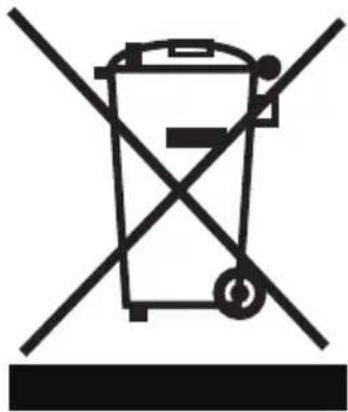
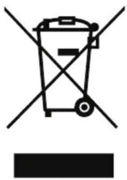
WEEE Warning:
Meaning of crossed out wheeled dustbin:
Do not dispose of electrical appliances as unsorted municipal waste, use separate collection facilities.
Contact you local government for information regarding the collection systems available.
If electrical appliances are disposed of in landfills or dumps, hazardous substances can leak into the groundwater and get into the food chain, damaging your health and well-being. When replacing old appliances with new ones, the retailer is legally obligated to take back your old appliance for disposals at least free of charge.
natural_image
Symbol of a trash bin crossed with no text or numbers, representing waste sorting or discharge (no text present)2 Safety precautions

Warning:
- Don't open the windows and doors for long time when the air conditioner is running. Otherwise, the cooling or heating capacity will be weakened.
- Don't stand on the top of the outdoor unit or place heavy things on it. This could cause personal injuries or damage the unit.
- Don't use the air conditioner for other purposes, such as drying clothes, preserving foods, etc.
- Don't apply the cold air to the body for a long time. It will deteriorate your physical conditions and cause health problems.
- Set the suitable temperature.
It is recommended that the temperature difference between indoor and outdoor temperature should not be too large.
Appropriate adjustments of the setting temperature can prevent the waste of electricity. - If your air conditioner is not fitted with a supply cord and a plug, an anti-explosion all-pole switch must be installed in the fixed wiring and the distance between contacts should be no less than 3.0mm (0.12in).
2 Safety precautions

Warning:
If your air conditioner is permanently connected to the fixed wiring, a anti-explosion residual current device (RCD) having rated residual operating current not exceeding 30 mA should be installed in the fixed wiring.
The power supply circuit should have leakage protector and air switch of which the capacity should be more than 1.5 times of the maximum current.
Regarding the installation of the air conditioners, please refer to the below paragraphs in this manual.
3 Notices for usage
3.1 The conditions of unit can't normally run
- Within the temperature range provided in following table, the air conditioner may stop running and other anomalies may arise.
| Cooling | Outdoor | >43°C (109°F) (Apply to T1) |
| >52°C (126°F) (Apply to T3) | ||
| Indoor <18°C | (64°F) | |
| Heating | Outdoor | >24°C (75°F) |
| <-7°C (19°F) | ||
| Indoor >27°C | (81°F) |
- When the temperature is too high, the air conditioner may activate the automatic protection device, so that the air conditioner could be shut down.
- When the temperature is too low, the heat exchanger of the air conditioner may freeze, leading to water dripping or other malfunction.
- In long-term cooling or dehumidification with a relative humidity of above 80% (doors and windows are open), there may be water condenses or dripping near the air outlet.
• T1 and T3 refer to ISO 5151.
3.2 Notes for heating
- The fan of the indoor unit will not work immediately when the heating is started to avoid blowing out cool air.
- When it is cold and wet outside, the outdoor unit will develop frost over the heat exchanger which will increase the heating capacity. Then the air conditioner will start defrost function.
- During defrost, the air conditioner will stop heating for about 5-12 minutes.
• Vapor may come out from the outdoor unit during defrost. This is not a malfunction, but a result of fast defrost.
• Heating will resume after defrost is complete.
3.3 Notes for turning off
- * When the air conditioner is turned off, the main controller will automatically decide whether to stop immediately or after running for dozens of seconds with lower frequency and lower air speed.
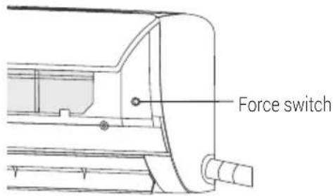
3.4 Emergency operation
- If the remote controller is lost or broken, use force switch button to operate the air conditioner.
- If this button is pushed with the unit OFF, the air conditioner will operate in Auto mode.
- If this button is pushed with the unit ON, the air conditioner will stop running.
3 Notices for usage
3.5 Airflow direction adjustment
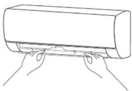
- Use up-down swing and left-right swing buttons on the remote controller to adjust the airflow direction. Refer to the operation manual of the remote controller for detail.
- For models without left-right swing function, the air vent has to be moved manually.

Note:
Move the air vents before the unit is in operation, or your finger might be injured.
Never place your hand into the air inlet or outlet when the air conditioner is in operation.
natural_image
Line drawing of hands installing or adjusting a cylindrical air conditioner cover (no text or symbols)3.6 Specific caution
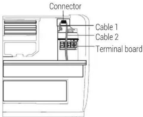
- Open front panel of the indoor.
- The connector (as Fig) can not touch the terminal board, and is positioned as shown in Fig.
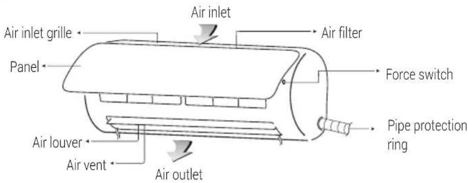
4 Names of each part
4.1 Indoor unit
There are two kinds about Indoor unit, Fig A, Fig B, the actual shape shall prevail.
Fig A
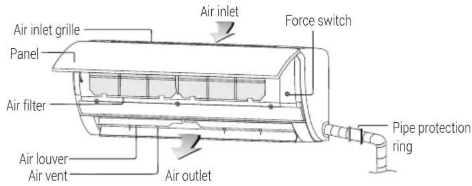
Fig B
4.2 Outdoor unit
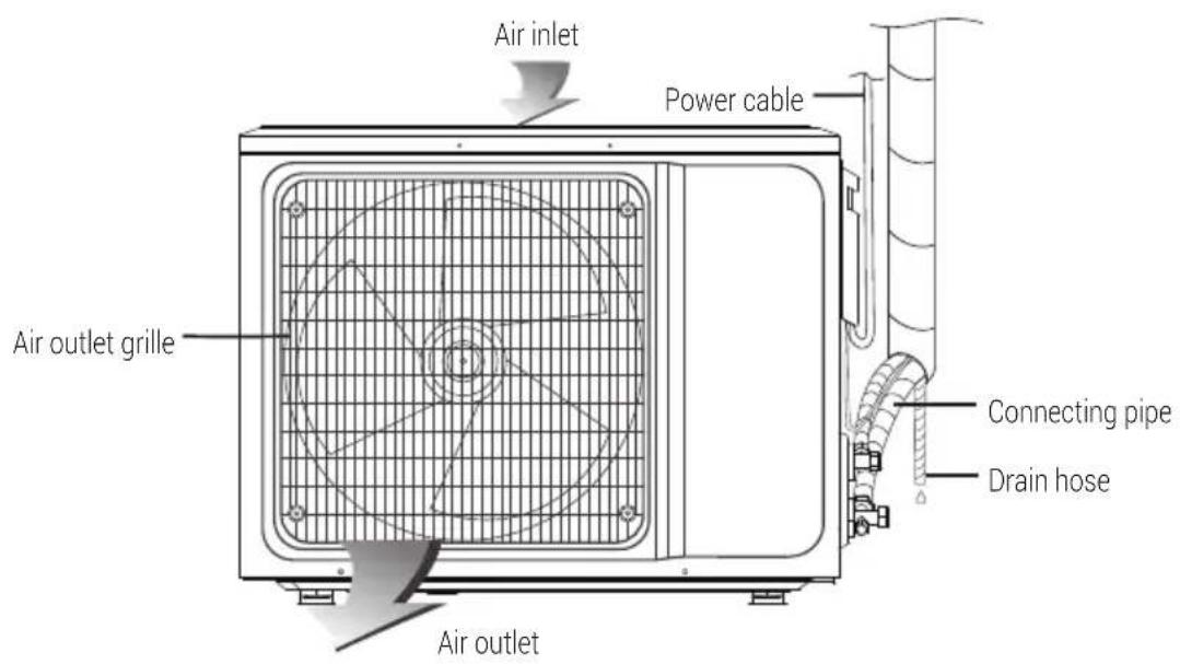
4 Names of each part

Note:
All the illustrations in this manual are for explanation purpose only.
Your air conditioner may be slightly different. The actual shape shall prevail. They are subject to change without notice for future improvement.
Plug, WIFI function, Negative-ion function, and Vertical and horizontal swing function both are optional, the actual unit shall prevail.
5 Clean and care

Warning:
- Before the cleaning of the air conditioner, it must be shut down and the electricity must be cut off for more than 5 minutes, otherwise there might be the risk of electric shocks.
- Do not wet the air conditioner, which can cause an electric shock. Make sure not to rinse the air conditioner with water under any circumstances.
- Volatile liquids such as thinner or gasoline will damage the air conditioner housing, therefore please clean the housing of air conditioner only with soft dry cloth and damp cloth moistened with neutral detergent.
- In the course of the usage, pay attention to cleaning the filter regularly, to prevent the accumulation of dust which may affect the air conditioner performance. If the service environment of the air conditioner is dusty, correspondingly increase the number of times of cleaning. After removing the filter, do not touch the fin part of the indoor unit with the finger, and no force to damage the refrigerant pipeline.
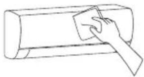
5.1 Clean the panel
When the panel of the indoor unit is contaminated, clean it gently with a wrung towel using tepid water below 40^ C ( 104^ F), and do not remove the panel while cleaning.
natural_image
Line drawing of a hand using a power tool to clean or brush the next page of a cylindrical object (no text or symbols)5.2 Clean the air filter
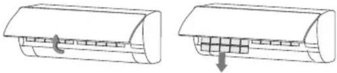
- Remove the air filter
natural_image
Diagram showing two views of a car air duct with internal grid structure, no text or symbols presentFig A
- Use both hands to open the panel for an angle from both ends of the panel in accordance with the direction of the arrow.
- Release the air filter from the slot and remove it.
natural_image
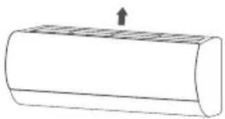
Simple line drawing of a cylinder with an upward arrow on top surface (no text or symbols)Fig B
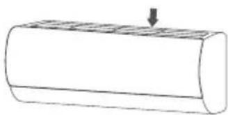
The air filter is locate above the fuselage.
Take it out facing upward.
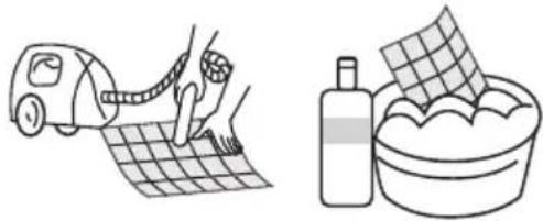
- Clean the Air Filter
Use a vacuum cleaner or water to rinse the filter, and if the filter is very dirty (for example, with greasy dirt), clean it with warm water (below 45^ C ( 113^ F)) with mild detergent, and then put the filter in the shade to dry in the air.
5 Clean and care
natural_image
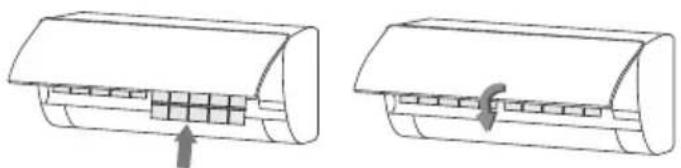
Illustration showing a car being cleaned on a grid surface next to a bowl of laundry (no text or symbols)- Mount the Filter
Reinstall the dried filter in reverse order of removal, then cover and lock the panel.
natural_image
Diagram showing two stages of a car airbag with internal components and directional arrows (no text or symbols)Fig A
Reinstall the dried filter in reverse order of removal.
natural_image
Simple line drawing of a cylindrical object with a downward arrow indicating force or direction (no text or symbols)Fig B
5.3 Check before using
- Check whether all the air inlets and outlets of the units are unblocked.
- Check whether there is blocking in the water outlet of the drain pipe, and immediately clean it up if any.
- Check the ground wire is reliably grounded.
- Check whether the remote control batteries are installed, and whether the power is sufficient.
- Check whether there is damage in the mounting bracket of the outdoor unit, and if any, please contact our local service center.
5.4 Maintain after using
- Cut off the power source of the air conditioner, turn off the main power switch and remove the batteries from the remote controller.
- Clean the filter and the unit body.
- Remove the dust and debris from the outdoor unit.
- Check whether there is damage in the mounting bracket of the outdoor unit, and if any, please contact our local service center.
6 Troubleshooting

Warning:
- Do not repair the air conditioner by yourself as wrong maintenance may cause electric shock or fire or explode, please contact the authorized service center and let the professionals conduct the maintenance, and checking the following items prior to contacting for maintenance can save your time and money.
Phenomenon Troubleshooting
| The air conditioner does not work. | ·There might be power outages. - Wait until power is restored. ·Power plug may be loose out from the socket. - The plug in the plug tightly. ·Power switch fuse may blow. - Replace the fuse. ·The time for timing boot is yet to come. - Wait or cancel the timer settings. |
| The air conditioner can't run after the immediate start-up after it is shut down. | ·If the air conditioner is turned on immediately after it is turned off, the protective delay switch will delay the operation for 3 to 5 minutes. |
| The air conditioner stops running after it starts up for a while. | ·May have reached the setting temperature. - It is a normal function phenomenon. ·May be at a defrosting state. - It will automatically restore and run again after defrosting. ·Shutdown Timer may be set. - If you continue to use, please turn it on again. |
6 Troubleshooting
Phenomenon Troubleshooting
| The wind blows out, but the cooling/heating effect is not good. | Excessive accumulation of dust on filter, blocking at air inlet and outlet, and the excessively small angle of the louver blades all will affect the cooling and heating effect.Please clean the filter, remove the obstacles at the air inlet and outlet and regulate the angle of the louver blades.Poor cooling and heating effect caused by doors and windows opening, and unclosed exhaust fan.Please close the doors, windows, the exhaust fan, etc.Auxiliary heating function is not turned on while heating, which may lead to poor heating effect.Turn on the auxiliary heating function.(only for models with auxiliary heating function)Mode setting is incorrect, and the temperature and wind speed settings are not appropriate.Please re-select the mode, and set the appropriate temperature and wind speed. |
| The indoor unit blows out odor. | The air conditioner itself does not have undesirable odor. If there is odor, it may be due to accumulation of the odor in the environment.Clean the air filter or activate the cleaning function. |
| There is sound of running water during the running of air conditioner. | When the air conditioner is started up or stopped, or the compressor is started up or stopped during the running, sometimes the "hissing" sound of running water can be heard.This is the sound of the flow of the refrigerant, not a malfunction. |
| A slight "click" sound is heard at the of start-up or shut-down. | Due to temperature changes, panel and other parts will swell, causing the sound of friction.This is normal, not a fault. |
6 Troubleshooting
| Phenomenon Troubleshooting | |
| The indoor unit makes abnormal sound. | · The sound of fan or compressor relay switched on or off.· When the defrosting is started or stop running, it will create sound.- That is due to the refrigerant flows to reverse direction. They are not malfunctions.· Too much dust accumulation on the air filter of the indoor unit may result in fluctuation of the sound.- Clean the air filters in time.· Too much air noise when “Strong wind” is turned on.- This is normal, if feeling uncomfortable, please deactivate the “Strong wind” function. |
| There are water drops over the surface of the indoor unit. | · When ambient humidity is high, water drops will be accumulated around the air outlet or the panel, etc.- This is a normal physics phenomenon.· Prolonged cooling run in open space produces water drops.- Close the doors and windows.· Too small opening angle of the louver blades may also result in water drops at the air inlet.- Increase the angle of the louver blades. |
| During the cooling operation, the indoor unit outlet sometimes will blow out mist. | · When the indoor temperature and humidity are high, it happens sometimes.- This is because the indoor air is cooled rapidly. After it runs for some time, the indoor temperature and humidity will be reduced and the mist will disappear. |

Warning:
Immediately stop all operations and cut off the power supply, contact our Service center locally in following situations.
- Hear any harsh sound or smell any awful odor during running.
• Abnormal heating of power cable and plug occurs. - The unit or remote controller has any impurity or water.
• Air switch or leakage protection switch is often disconnected.

Important notices:
- Before installation, please contact with local authorized maintenance center, if unit is not installed by the authorized maintenance center, the malfunction may not be solved, due to discommodious contact.
- The air conditioner must be installed by professionals according to the national wiring rules and this manual.
- Leak test must be made after installation.
• To move and install air conditioner to another place, please contact our local special service center.
7.1 Unpacking Inspection
- Open the box and check air conditioner in area with good ventilation (open the door and window) and without ignition source.

Note:
Operators are required to wear anti-static devices.
- It is necessary to check whether there is refrigerant leakage before opening the box of outdoor machine; stop installing the air conditioner if leakage is found.
- The fire prevention equipment shall be prepared well before checking.
Then check the refrigerant pipeline to see if there is any collision traces, and whether the outlook is good.
7.2 Safety Principles for Installing Air Conditioner
- Fire prevention device shall be prepared before installation.
- Keep installing site ventilated.(open the door and window)
- Ignition source, smoking and calling is not allowed to exist in area where R32 refrigerant located.
- Anti-static precautions in necessary for installing air conditioner, e.g. wear pure cotton clothes and gloves.
- Keep leak detector in working state during the installation.
- If R32 refrigerant leakage occurs during the installation, you shall immediately detect the concentration in indoor environment until it reaches a safe level. If refrigerant leakage affects the performance of the air conditioner, please immediately stop the operation, and the air conditioner must be vacuumed firstly and be returned to the maintenance station for processing.
- Keep electric appliance, power switch, plug, socket, high temperature heat source and high static away from the area underneath sidelines of the indoor unit.
- The air conditioner shall be installed in an accessible location to installation and maintenance, without obstacles that may block air inlets or outlets of indoor /outdoor units, and shall keep away from heat source, inflammable or explosive conditions.
- When installing or repairing the air conditioner and the connecting line is not long enough, the entire connecting line shall be replaced with the connecting line of
7 Notices for installation
the original specification; extension is not allowed.
7.3 Requirements for installation position
- Avoid places of inflammable or explosive gas leakage or where there are strongly aggressive gases.
- Avoid places subject to strong artificial electric/magnetic fields.
- Avoid places subject to noise and resonance.
- Avoid severe natural conditions (e.g. heavy lampblack, strong sandy wind, direct sunshine or high temperature heat sources).
- Avoid places within the reach of children.
- Shorten the connection between the indoor and outdoor units.
- Select where it is easy to perform service and repair and where the ventilation good.
- The outdoor unit shall not be installed in any way that could occupy an aisle, stairway, exit, fire escape, catwalk or any other public area.
- The outdoor unit shall be installed as far as possible from the doors and windows of the neighbors as well as the green plants.
7.4 Installation environment inspection
- Check nameplate of outdoor machine to make sure whether the refrigerant is R32.
- Check the floor space of the room. The space shall not be less than usable space in the specification. The outdoor unit shall be installed at a well-ventilated place.
- Check the surrounding environment of installation site: R32 shall not be installed in the enclosed reserved space of a building.
- When using electric drill to make holes in the wall, check first whether there is pre-buried pipeline for water, electricity and gas. It is suggested to use the reserved hole in the roof of the wall.
7.5 Requirements of the mounting structure
- The mounting rack must meet the relevant national or industrial standards in terms of strength with welding and connection areas rustproofed.
- The mounting rack and its load carry surface shall be able to withstand 4 times or above the weight of the unit, or 200kg, whichever is heavier.
- The mounting rack of the outdoor unit shall be fastened with expansion bolt.
- Ensure the secure installation regardless of what type of wall on which it is installed, to prevent potential dropping that could hurt people.
7.6 Installation guide at the seaside
- Air conditioners should not be installed in areas where corrosive gases, such as acid alkaline gas, are produced.
- Do not install the product where it could be exposed to sea wind (salty wind) directly. It can result corrosion on the product. Corrosion, particularly on the condenser and evaporator fins, could cause product malfunction or inefficient performance.
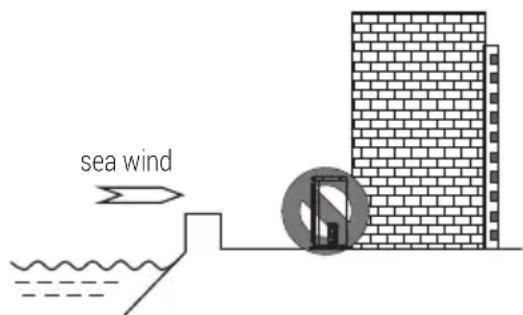
- If outdoor unit is installed close to the seaside, it should avoid direct exposure to the sea wind. Otherwise it needs additional anticorrosion treatment on the heat exchanger.
- Select a well-drained place.
- Selecting the location (outdoor unit)
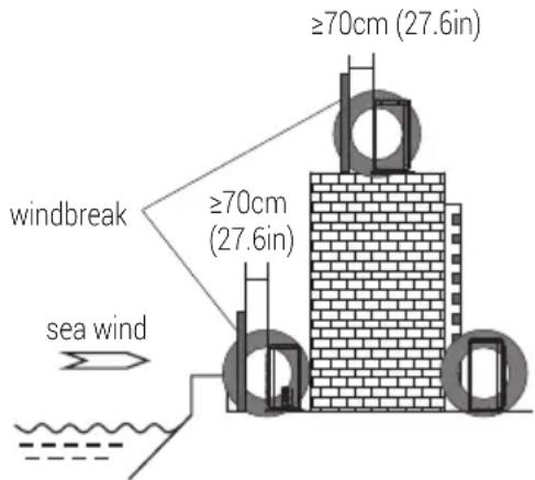
Install the outdoor unit on the opposite side of the sea wind direction, or set up a windbreak to avoid exposed to the sea wind.
- The windbreak should be strong enough like concrete to prevent the sea wind from the sea. The height and width should be more than 150% of the outdoor unit.
- It should be keep more than 70cm (27.6in) of space between outdoor unit and the windbreak for easy air flow.
Periodic (more than once/year) cleaning of the dust or salt particles stuck on the heat exchanger by using water.
- The mounting rack of the outdoor unit shall be fastened with expansion bolt.
- Ensure the secure installation regardless of what type of wall on which it is installed, to prevent potential dropping that could hurt people.
7.7 Electrical Safety Requirements
- Be sure to use the rated voltage and air conditioners dedicated circuit for the power supply, and the power cable diameter must meet the national requirements.
- When the maximum current of air conditioner is ≥ 16A , it must use the air switch or leakage protection switch equipped with protection devices.
- The operating range is 90%-110% of the local rated voltage. But insufficient power supply malfunction, electrical shock, or fire. If the voltage instability, proposed to increase the voltage regulator.
- The minimum clearance between the air conditioner and the combustibles is 1.5m(4.9ft).
- The interconnection cord connect the indoor and outdoor units. You must first choose the right cable size before preparing it for connection.
- The supply cord of appliances for outdoor use shall be between 1.5(4.9ft) and 3m (9.8ft) long and shall be either an EXTRA HARD USAGE or a HARD USAGE CORD. (Only for the AC with UL or ETL-MARKING, UL60335-2-40) Cable Types: Outdoor Power Cable: H07RN-F or H05RN-F; Interconnection cord: H07RN-F or H05RN-F; (For the AC with CE-MARKING & CB-MARKING, IEC 60335-2-40+A1:2016)
7 Notices for installation
- Minimum Cross-Sectional Area of Power cable and interconnection cord.
| Certification Type | Appliance Amps (A) | Recommended Wire Model (AWG) |
| UL | <10 18 | |
| <13 16 | ||
| <18 14 | ||
| <25 12 | ||
| <30 10 | ||
| <40 8 | ||
| <55 6 |

Note:
To ensure safety, the wire diameter can be larger and smaller is prohibited.
| Certification Type | Circuit Amps(A) | Nominal Cross-Sectioal Area( mm^2 ) |
| VDE | <6 0.75 | |
| <10 1.0 | ||
| <16 1.5 | ||
| <25 2.5 | ||
| <32 4 | ||
| <40 6 |

Note:
To ensure safety, the wire diameter can be larger and smaller is prohibited.
- The size of the interconnection cord, power cable, fuse, and switch needed is determined by the maximum current of the unit. The maximum current is indicated on the nameplate located on the side panel of the unit. Refer to this nameplate to choose the right cable, fuse, or switch.

Note:
Core number of cable refer to the detailed wiring diagram adhered on the unit which you purchased.
- Means for disconnection must be incorporated in the fixed wiring in accordance with the wiring rules.
7.8 Requirements for operations at raised height
- When carrying out installation at 2m(6.6ft) or higher above the base level, safety belts must be worn and ropes of sufficient strength be securely fasten to the outdoor unit, to prevent falling that could cause personal injury or death as well as property loss.
7.9 Grounding Requirements
- The air conditioner is the class I electrical appliance and must ensure a reliable grounding.
- Do not connect the grounding wire to a gas pipe, water pipe, lightning rod, telephone line, or a circuit poorly grounded to the earth.
- The grounding wire is specially designed and shall not be used for other purpose, nor shall it be fastened with a common tapping screw.
7 Notices for installation
- Interconnection cord diameter should be recommended as per instruction manual, and with type O terminal that meet local standards (internal diameter of type O terminal needs to match the screw size of the unit, no more than 4.2mm(0.17in)). After installation, check the screws whether have been fixed effectively, and there is no risk of loosening.
7.10 Others
- The connection method of the air conditioner and the power cable and the interconnection method of each independent element shall be subject to the wiring diagram affixed to the machine.
- The model and rating value of the fuse shall be subject to the silkscreen on corresponding controller or fuse sleeve.
7.11 Packing list
Packing list of the indoor unit
| Name Quantity | Unit | |
| Indoor Unit 1 Set | ||
| Remote Controller(*) 1 | PC | |
| Batteries(7#)(*) 2 PC | ||
| Instructions 1 Set | ||
| Drain pipe (*) 1 PC |
Packing list of the outdoor unit
| Name Quantity | Unit | |
| Outdoor Unit 1 Set | ||
| Connecting pipe(*) | 2 | PC |
| Plastic Strap(*) | 1 ROLL | |
| Pipe Protection Ring(*) | 1 | PC |
| Luting (putty) (*) | 1 | PACKET |

Note:
Optional parts(*), some models without.
Interconnection cord and sound deadening pads is optional accessorie.
All accessories shall be subject to actual packaging material, and if there is any difference, please understand.
8 Installation for indoor unit
8.1 Dimension drawing of indoor unit installation
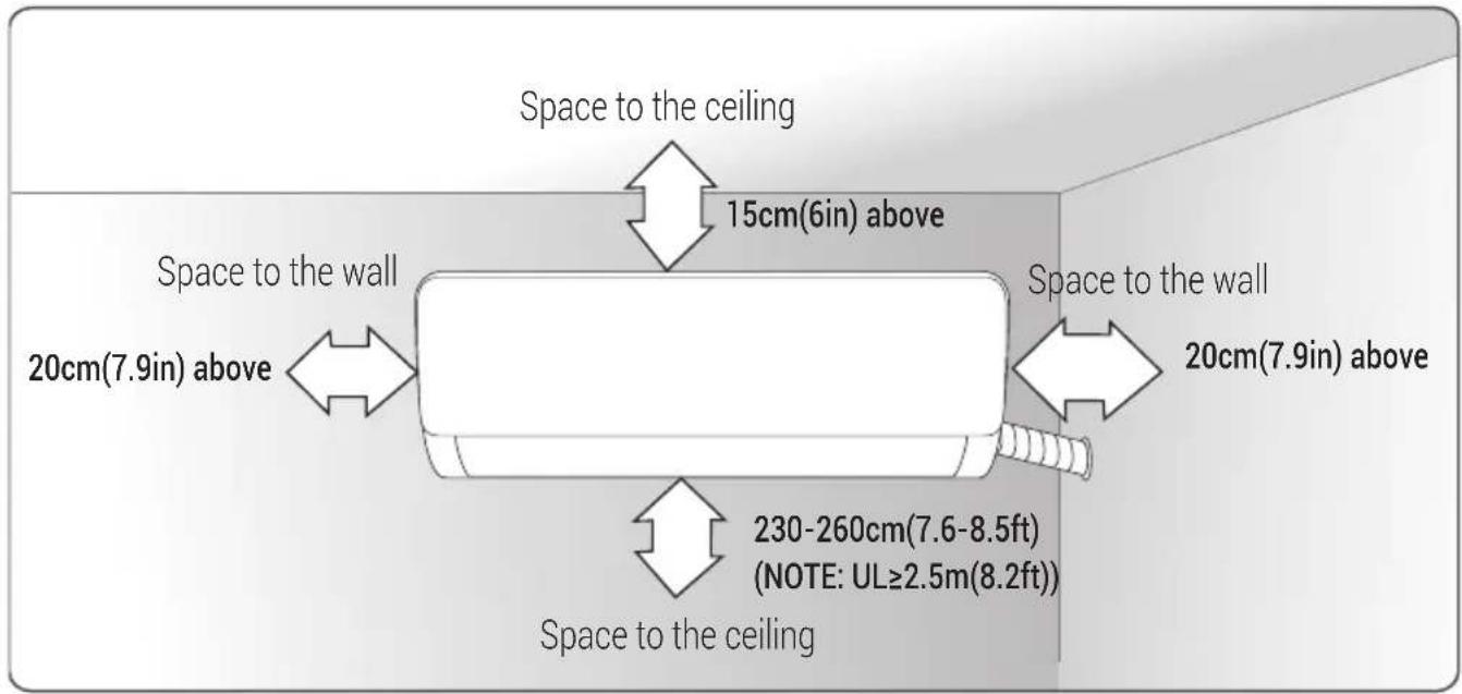
8.2 Mounting plate
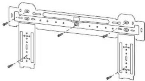
- The wall for installation of the indoor unit shall be hard and firm, so as to prevent vibration.
- Use the "+" type screw to fasten the peg board, horizontally mount the peg board on the wall, and ensure the lateral horizontal and longitudinal vertical.
- Pull the peg board by hand after the installation, to confirm whether it is solid.
natural_image
Technical line drawing of a mechanical assembly with mounting brackets and mounting holes (no text or symbols)8.3 Wall-through Hole
-
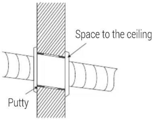
Make a hole with an electric hammer or a water drill at the predetermined position on the wall for piping, which shall slant outwardly by 5^-10^ .
-
To protect the piping and the cables from being damaged running through the wall, and from the rodents that may inhabit in the hollow wall, a pipe protecting ring shall be installed and sealed with putty.

Note:
Usually, the wall hole is 60mm 80mm . Avoid preburied power wire and hard wall when making the hole.
8 Installation for indoor unit
8.4 Route of Pipeline
- Depending on the position of the unit, the piping may be routed sideways from the left or the right (Fig 1), or vertically from the back (Fig 2) (depending on the pipe length of the indoor unit). In the case of sideways routing, cut off the outlet cutting stock of the opposite side.
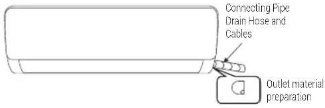
Fig 1
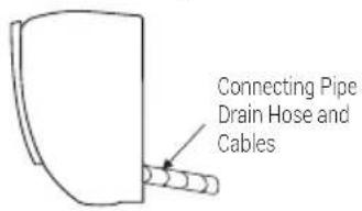
Fig 2
8.5 Install the connection pipe
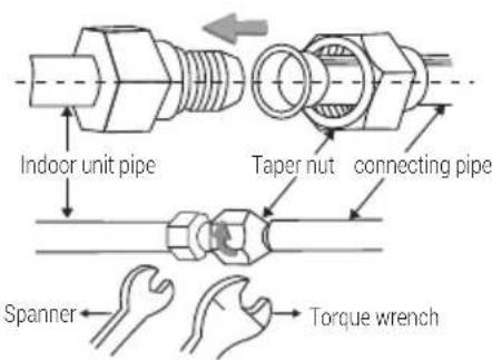
- Remove the fixed part to pull out pipe of indoor machine from the case. Screw the hexagon nut in the left of the joint to the end with your hand.
- Connect the connecting pipe to the indoor unit:
Aim at the pipe center, tighten the Taper nut with fingers, and then tighten the Taper nut with a torque wrench, and the direction is shown in diagram on the right. The torque used is shown in the following table.

Note:
Carefully check if there is any damage of joints before installation.
The joints shall not be reused, unless after re-flaring the pipe.
Tightening torque table
| The size of pipe (mm(in)) Torque (N·m) | |
| 6/ 6.35(1/4) 15-25 | |
| 9/ 9.52(3/8) 35-40 | |
| 12/ 12.7(1/2) 45-60 | |
| 15.88(5/8) 73-78 | |
| 19.05(3/4) 75-80 | |

Important note:
If the unit with the quick connectors, please refer to the booklet of "Install the connection pipe (the unit with the quick connectors)".
8.6 Wrap the Piping
- Use the insulation sleeve to wrap the joint part the indoor unit and the connection pipe, and then use insulating material to pack and seal insulation pipe, to prevent generation of condensate water on the joint part.
8 Installation for indoor unit
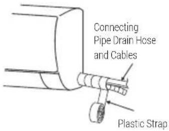
- Connect the water outlet with drain pipes, and make the connection pipe, cables, and the drain hose straight.
- Use plastic cable ties to wrap the connecting pipes, cables and drain hose. Run the pipe sloping downward.
8.7 Fixing the Indoor Unit
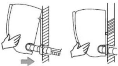
- Hang the indoor unit on the peg board, and move the unit from left to right to ensure that the hook is properly positioned in the peg board.
- Push toward the lower left side and the upper right side of the unit toward the peg board, until the hook is embedded in the slot and makes a "click" sound.
natural_image
Two-step diagram showing hand positioning and tool application on a mechanical component (no text or symbols)8.8 Interconnection cord installation
- Connect interconnection cord of indoor unit
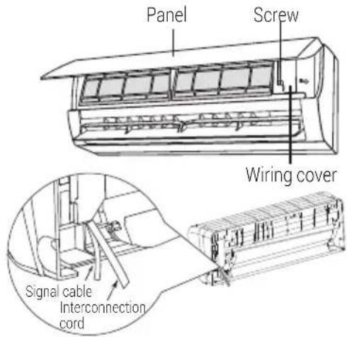
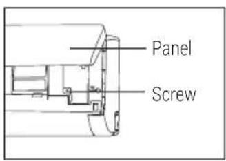
- Open the panel, remove the screw on the wiring cover and then take down the cover.
-
Make the interconnection cord go through the cable-cross hole at the back of indoor unit and then pull it out from the front side. (Some models do not have a signal cable.)
-
Remove the wire clip; connect the interconnection cord to the wiring terminal according to the wiring diagram; tighten the screw and then fix the interconnection cord with wire clip.
Note:
• This manual usually includes the wiring mode for the different kind of air conditioner. We cannot exclude the possibility that some special type of wiring diagrams are not included.
- The diagram are for reference only. If the entity is difference with this wiring diagram, please refer to the detailed wiring diagram adhered on the unit which you purchased.
8 Installation for indoor unit
Constant speed
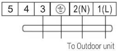
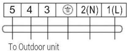
• After installation check
-
The screws whether have been fixed effectively, and there is no risk of loosening.
-
Connector of display board whether put in the right place and do not touch the terminal board.
-
Control box cover whether cover tightly.
Variable speed
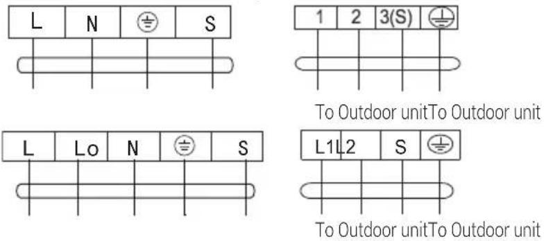
Connector
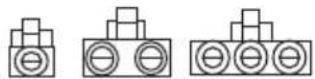
If there is a connector, connect it directly.
-
Put wiring cover back and then tighten the screw.
-
Close the panel.
9 Installation for outdoor unit
9.1 Dimension drawing of outdoor unit installation
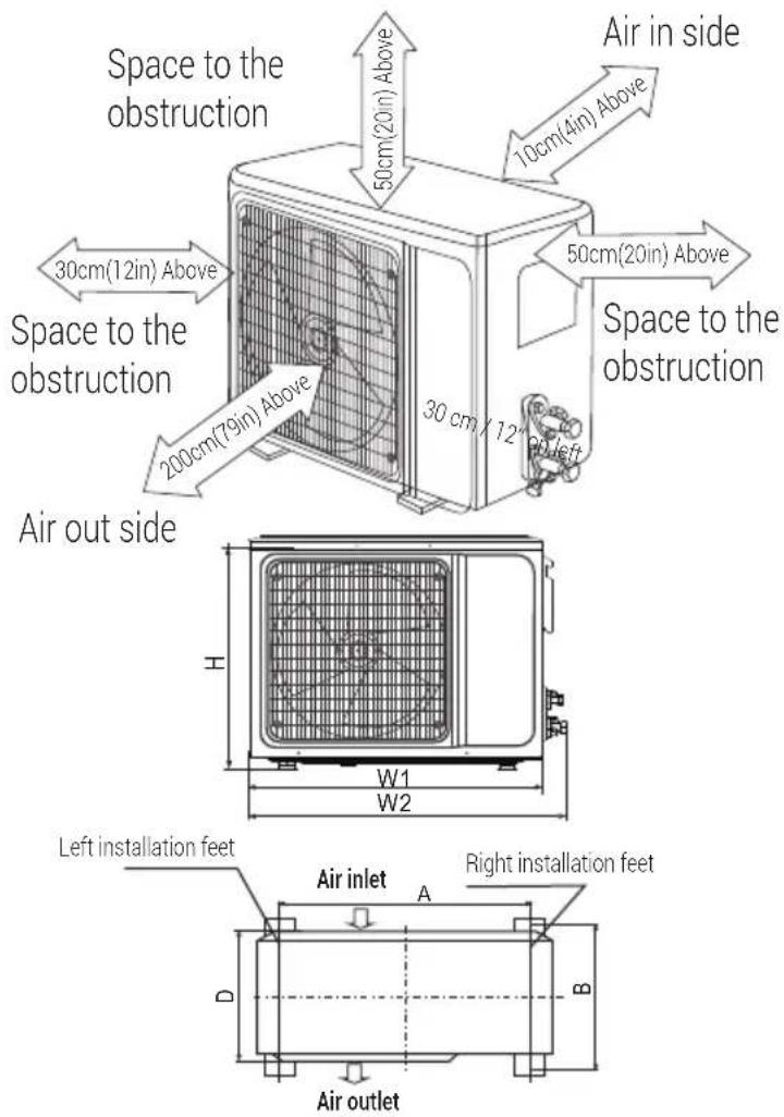
Installation outdoor unit bolt
| Outdoor Unit Size of Shape W1(W2)*H*D) mm(in) | A mm(in) | B mm(in) |
| 665(710)×420×28026.2(28.0)×16.5×11.0 | 430(16.9) | 280(11.0) |
| 660(710)×500×24026.0(28.0)×19.7×9.4 | 500(19.7) | 260(10.2) |
| 730(780)×545×28528.7(30.7)×21.5×11.2 | 540(21.3) | 280(11.0) |
| 709(761)×536×28027.9(30.0)×21.1×11.0 | 480(18.9) | 283(11.1) |
| 750(804)×550×28529.5(31.7)×21.7×11.2 | 480(18.9) | 283(11.1) |
| 800(860)×545×31531.5(33.9)×21.5×12.4 | 545(21.5) | 315(12.4) |
| Outdoor Unit Size of Shape W1(W2)*H*D) mm(in) | A mm(in) | B mm(in) |
| 785(845)x555x300 30.9(33.3)x21.9x11.8 | 546(21.5) | 316(12.4) |
| 825(880)x655x335 32.5(34.6)x25.8x13.2 | 540(21.3) | 335(13.2) |
| 900(950)x700x360 35.4(37.4)x27.6x14.2 | 632(24.9) | 352(13.9) |
| 970(1044)x805x395 38.2(41.1)x31.7x15.6 | 675(24.6) | 410(16.1) |
| 940(1010)x1320x370 37.0(39.8)x52.0x14.6 | 625(24.6) | 364(14.3) |
| 940(1008)x1366x401 37.0(39.7)x53.8x15.8 | 610(24.0) | 388(15.3) |
| 650(703)x455x233 25.6(27.7)x17.9x9.2 | 480(18.9) | 253(10.0) |
9.2 Install the connection pipe
Connect the Outdoor Unit with Connecting Pipe:
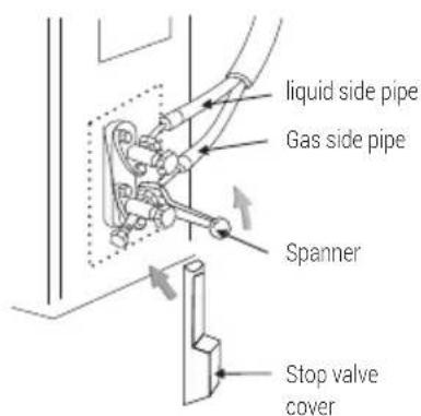
Aim the counter-bore of the connecting pipe at the stop valve, and tighten the Taper nut with fingers.
Then tighten the Taper nut with a torque wrench.
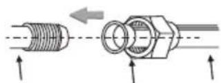
Stop valve Taper nut Connection pipe
- When the length of the connecting pipe is changed, extra amount of refrigerant need to be added or reduced, so that the operation and performance of the air conditioner will not be compromised.
9 Installation for outdoor unit
| Length of connection pipe Added or reduced refrigerant Amount of refrigerant for the unit | |||
| <3M(9.8ft) | CC≤12000Btu reduce | ce 20g/m ≤1Kg | |
| CC≤12000Btu reduce | ce 40g/m ≤2Kg | ||
| 3-5M(9.8-16.4ft) Not needed | |||
| 5-15M(16.4-49.2ft) | CC≤12000Btu add | 16g/m ≤1Kg | |
| CC≥18000Btu add | 24g/m ≤2Kg | ||

Note:
- This table is for reference only.
- The joints shall not be reused, unless after re-flaring the pipe.
- After installation, check the stop valve cover whether be fixed effectively.

Important note:
If the unit with the quick connectors, please refer to the booklet of "Install the connection pipe (the unit with the quick connectors)".
9.3 Wiring Connection
- Loosen the screws and remove E-parts cover from the unit.
- Connect the cables respectively to the corresponding terminals of the terminal board of the outdoor unit (see the wiring diagram), and if there are signals connected to the plug, just conduct butt joint.
- Ground wire: Remove the grounding screw out of the electric bracket, cover the grounding wire end onto the grounding screw and screw it into the grounding hole.
- Fix the cable reliably with fasteners (Pressing board).
- Put the E-parts cover back in its original place and fasten it with screws.
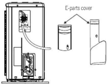
9 Installation for outdoor unit
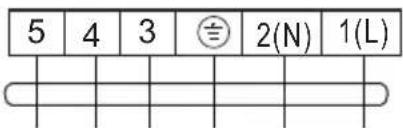
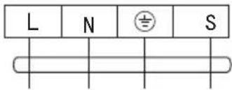
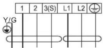
9.4 Wiring diagram
Constant speed
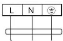
To power
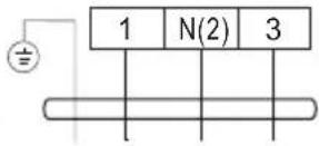
To Indoor unit
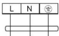
To power
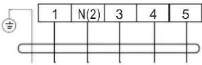
To Indoor unit
Variable speed
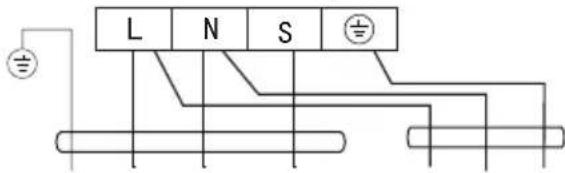
To Indoor unit
To power
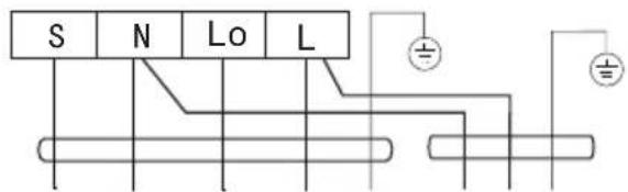
To Indoor unit
To power
Variable speed
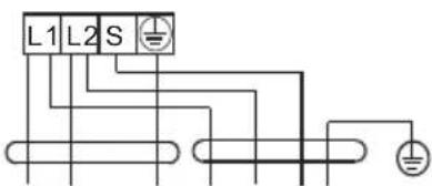
To Power To Power To PowerTo Indoor Unit To Indoor Unit To Indoor Unit
115V:
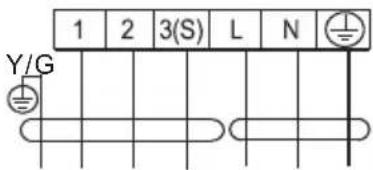
220V:
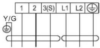
Connector

If there is a connector, connect it directly.

Note:
• This manual usually includes the wiring mode for the different kind of air conditioner. We cannot exclude the possibility that some special type of wiring diagrams are not included.
- The diagram are for reference only. If the entity is difference with this wiring diagram, please refer to the detailed wiring diagram adhered on the unit which you purchased.
9 Installation for outdoor unit
9.5 Vacuuming
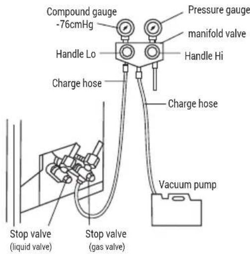
9.5.1 Exclusive R32 refrigerant pump must be used in making R32 refrigerant vacuum.
Before working on the air conditioner, remove the cover of the stop valve (gas and liquid valves) and be sure to retighten it afterward. (to prevent the potential air leakage).
- To prevent air leakage and spilling tighten all connecting nut of all flare tubes.
- Connect the stop valve, charge hose, manifold valve, and vacuum pump.
- Fully open the handle Lo of the manifold valve and apply vacuum for at least 15 minutes and check that the compound vacuum gauge reads -0.1MPa (-76cmHg).
- After applying vacuum, fully open the stop valve with a hex wrench.
- Check that both indoor and outdoor connections are free of air leakage.

Note: The unit with the quick connectors does not require vacuum pumping.
9.6 Outdoor condensation drainage (Heat pump type only)
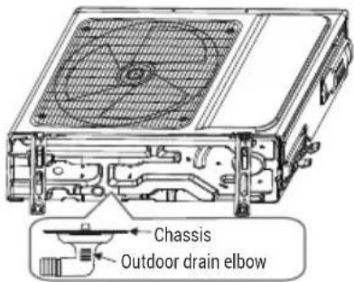
When the unit is heating, the condensing water and defrosting water can be out reliably through the drain house.
Installation:
Install the outdoor drain elbow in 25mm(1in) hole on the base plate, and joint the drain hose to the elbow, so that the waste water formed in the outdoor unit can be drained out to a proper plate.
10 Check after installation and test operation
10.1 Check after installation
10.1.1 Electrical safety check
- If the supply voltage is as required.
- If there is any faulty or miss connection in each of the power, signal and grounding wires.
- If the grounding wire of the air conditioner is securely grounded.
10.1.2 Installation safety check
- If the installation is secure.
- If the water drain is smooth.
- If the wiring and piping are correctly installed.
- Check that no foreign matter or tools are left inside the unit.
- Check the refrigerant pipeline is protected well.
10.1.3 Leak test of the refrigerant
Depending on the installation method, the following methods may be used to check for suspect leak, on areas such as the four connections of the outdoor unit and the cores of the cut-off valves and t-valves:
- Bubble method: Apply of spray a uniform layer of soap water over the suspected leak spot and observe carefully for bubble.
- Instrument method: Checking for leak by pointing the probe of the leak detector according to the instruction to the suspect points of leak.

Note: Make sure that the ventilation is good before checking.
10.2 Test operation
Test Operation preparation:
- Verify that all piping and connection cables are well connected.
- Confirm that the valve at the gas side the liquid-side are fully open.
- Connect the power cable to an independent power socket.
• Install batteries in remote control.

Note: Make sure that the ventilation is good before testing.
10.3 Test Operation method:
- Turn on the power and push the ON/OFF switch button of the remote controller to start the air conditioner.
- Select COOL, HEAT (not available on cool-only models), SWING and other operation modes with the remote controller and see if the operation is ok.
11 Maintenance Notice

Note:
For maintenance or scrap, please contact authorized service centers.
Maintenance by unqualified person may cause dangers.
Feed air conditioner with R32 refrigerant, and maintain the air conditioner in strictly accordance with manufacturer's requirements. The chapter is mainly focused on special maintenance requirements for appliance with R32 refrigerant.
Ask repairer to read after-sales technical service handbook for detailed information.
11.1 Qualification requirements of maintenance personnel
- Special training additional to usual refrigerating equipment repair procedures is required when equipment with flammable refrigerants is affected. In many countries, this training is carried out by national training organisations that are accredited to teach the relevant national competency standards that may be set in legislation. The achieved competence should be documented by a certificate.
- The maintenance and repair of the air conditioner must be conducted according to the method recommended by the manufacturer. If other professionals are needed to help maintain and repair the equipment, it should be conducted under the supervision of individuals who have the qualification to repair AC equipped with flammable refrigerant.
11.2 Inspection of the Site
Safety inspection must be taken before maintaining equipment with R32 refrigerant to make sure the risk of fire is minimized. Check whether the place is well ventilated, whether anti-static and fire prevention equipment is perfect.
While maintaining the refrigeration system, observe the following precautions before operating the system.
11.3 Operating Procedures
- General work area:
All maintenance staff and others working in the local area shall be instructed on the nature of work being carried out. Work in confined spaces shall be avoided. The area around the workspace shall be sectioned off. Ensure that the conditions within the area have been made safe by control of flammable material.
- Checking for presence of refrigerant:
The area shall be checked with an appropriate refrigerant detector prior to and during work, to ensure the technician is aware of potentially toxic or flammable atmospheres. Ensure that the leak detection equipment being used is suitable for use with all applicable refrigerants, i.e. non-sparking, adequately sealed or intrinsically safe.
- Presence of fire extinguisher:
If any hot work is to be conducted on the refrigeration equipment or any associated parts, appropriate fire extinguishing equipment shall be available to hand. Have a dry powder or CO2 fire extinguisher adjacent to the charging area.
11 Maintenance Notice
- No ignition sources:
No person carrying out work in relation to a refrigeration system which involves exposing any pipe work shall use any sources of ignition in such a manner that it may lead to the risk of fire or explosion. All possible ignition sources, including cigarette smoking, should be kept sufficiently far away from the site of installation, repairing, removing and disposal, during which refrigerant can possibly be released to the surrounding space. Prior to work taking place, the area around the equipment is to be surveyed to make sure that there are no flammable hazards or ignition risks. 'No Smoking' signs shall be displayed.
- Ventilated Area (open the door and window):
Ensure that the area is in the open or that it is adequately ventilated before breaking into the system or conducting any hot work. A degree of ventilation shall continue during the period that the work is carried out. The ventilation should safely disperse any released refrigerant and preferably expel it externally into the atmosphere.
- Checks to the refrigeration equipment:
Where electrical components are being changed, they shall be fit for the purpose and to the correct specification. At all times the manufacturer's maintenance and service guidelines shall be followed. If in doubt, consult the manufacturer's technical department for assistance. The following checks shall be applied to installations using flammable refrigerants:
- The charge size is in accordance with the room size within which the refrigerant containing parts are installed.
- The ventilation machinery and outlets are operating adequately and are not obstructed.
- If an indirect refrigerating circuit is being used, the secondary circuit shall be checked for the presence of refrigerant.
- Refrigeration pipe or components are installed in a position where they are unlikely to be exposed to any substance which may corrode refrigerant containing components, unless the components are constructed of materials which are inherently resistant to being corroded or are suitably protected against being so corroded.
- Checks to electrical devices:
Repair and maintenance to electrical components shall include initial safety checks and component inspection procedures. If a fault exists that could compromise safety, then no electrical supply shall be connected to the circuit until it is satisfactorily dealt with. If the fault cannot be corrected immediately but it is necessary to continue operation, an adequate temporary solution shall be used. This shall be reported to the owner of the equipment so all parties are advised. Initial safety checks shall include:
- That capacitors are discharged: this shall be done in a safe manner to avoid possibility of sparking.
- That no live electrical components and wiring are exposed while charging, recovering or purging the system.
- Keep continuity of earthing.
11 Maintenance Notice
11.4 Inspection of Cable
Check the cable for wear, corrosion, overvoltage, vibration and check if there are sharp edges and other adverse effects in the surrounding environment. During the inspection, the impact of aging or the continuous vibration of the compressor and the fan on it should be taken into consideration.
11.5 Leakage check of R32 refrigerant

Note:
Check the leakage of the refrigerant in an environment where there is no potential ignition source. No halogen probe (or any other detector that uses an open flame) should be used.
Leak detection method:
For systems with refrigerant R32, electronic leak detection instrument is available to detect and leak detection should not be conducted in environment with refrigerant. Make sure the leak detector will not become a potential source of ignition, and is applicable to the measured refrigerant. Leak detector shall be set for the minimum ignitable fuel concentration (percentage) of the refrigerant. Calibrate and adjust to proper gas concentration (no more than 25%) with the used refrigerant.
The fluid used in leak detection is applicable to most refrigerants. But do not use chloride solvents to prevent the reaction between chlorine and refrigerants and the corrosion of copper pipeline.
If you suspect a leak, then remove all the fire from the scene or put out the fire.
If the location of the leak needs to be welded, then all refrigerants need to be recovered, or, isolate all refrigerants away from the leak site (using cut-off valve). Before and during the welding, use OFN to purify the entire system.
11.6 Removal and Vacuum Pumping
- Make sure there is no ignited fire source near the outlet of the vacuum pump and the ventilation is well.
-
Allow the maintenance and other operations of the refrigeration circuit should be carried out according to the general procedure, but the following best operations that the flammability is already taken into consideration are the key. You should follow the following procedures:
-
Remove the refrigerant.
- Decontaminate the pipeline by inert gases.
•Evacuation. - Decontaminate the pipeline by inert gases again.
-
Cut or weld the pipeline.
-
The refrigerant should be returned to the appropriate storage tank. The system should be blown with oxygen free nitrogen to ensure safety. This process may need to be repeated for several times. This operation shall not be carried out using compressed air or oxygen.
-
Through blowing process, the system is charged into the anaerobic nitrogen to reach the working pressure under the vacuum state, then the oxygen free nitrogen is emitted to the atmosphere, and in the end, vacuumize the system. Repeat this process until all refrigerants in the system is cleared. After the final charging of the anaerobic nitrogen,
11 Maintenance Notice
discharge the gas into the atmosphere pressure, and then the system can be welded. This operation is necessary for welding the pipeline.
11.7 Procedures of Charging Refrigerants
As a supplement to the general procedure, the following requirements need to be added:
- Make sure that there is no contamination among different refrigerants when using a refrigerant charging device. The pipeline for charging refrigerants should be as short as possible to reduce the residual of refrigerants in it.
-Storage tanks should remain vertically up. - Make sure the grounding solutions are already taken before the refrigeration system is charged with refrigerants.
- After finishing the charging (or when it is not yet finished), label the mark on the system.
-Be careful not to overcharge refrigerants.
11.8 Scrap and Recovery
Scrap:
Before this procedure, the technical personnel shall be thoroughly familiar with the equipment and all its features, and make a recommended practice for refrigerant safe recovery. For recycling the refrigerant, shall analyze the refrigerant and oil samples before operation. Ensure the required power before the test.
- Be familiar with the equipment and operation.
- Disconnect power supply.
- Before carrying out this process, you have to make sure:
- If necessary, mechanical equipment operation should facilitate the operation of the refrigerant tank.
- All personal protective equipment is effective and can be used correctly.
- The whole recovery process should be carried out under the guidance of qualified personnel.
- The recovering of equipment and storage tank should comply with the relevant national standards.
- If possible, the refrigerating system should be vacuumized.
- If the vacuum state can't be reached, you should extract the refrigerant in each part of the system from many places.
- Before the start of the recovery, you should ensure that the capacity of the storage tank is sufficient.
- Start and operate the recovery equipment according to the manufacturer's instructions.
- Don't fill the tank to its full capacity (the liquid injection volume does not exceed 80% of the tank volume).
- Even the duration is short, it must not exceed the maximum working pressure of the tank.
- After the completion of the tank filling and the end of the operation process, you should make sure that the tanks and equipment should be removed quickly and all closing valves in the equipment are closed.
- The recovered refrigerants are not allowed to be injected into another system before being purified and tested.
11 Maintenance Notice

Note:
The identification should be made after the appliance is scrapped and refrigerants are evacuated. The identification should contain the date and endorsement. Make sure the identification on the appliance can reflect the flammable refrigerants contained in this appliance.
Recovery:
- The clearance of refrigerants in the system is required when repairing or scrapping the appliance. It is recommended to completely remove the refrigerant.
-
Only a special refrigerant tank can be used when loading the refrigerant into the storage tank. Make sure the capacity of the tank is appropriate to the refrigerant injection quantity in the entire system. All tanks intended to be used for the recovery of refrigerants should have a refrigerant identification (i.e. refrigerant recovery tank). Storage tanks should be equipped with pressure relief valves and globe valves and they should be in a good condition. If possible, empty tanks should be evacuated and maintained at room temperature before use.
-
The recovery equipment should be kept in a good working condition and equipped with equipment operating instructions for easy access. The equipment should be suitable for the recovery of R32 refrigerants. Besides, there should be a qualified weighting apparatus which can be normally used. The hose should be linked with detachable connection joint of zero leakage rate and be kept in a good condition.
Before using the recovery equipment, check if it is in a good condition and if it gets perfect maintenance. Check if ll electrical components are sealed to prevent the leakage of the refrigerant and the fire caused by it. If you have any question, please consult the manufacturer.
- The recovered refrigerant shall be loaded in the appropriate storage tanks, attached with a transporting instruction, and returned to the refrigerant manufacturer. Don't mix refrigerant in recovery equipment, especially a storage tank.
- The space loading R32 refrigeration can't be enclosed in the process of transportation. Take anti electrostatic measures if necessary in transportation. In the process of transport, loading and unloading, necessary protective measures must be taken to protect the air conditioner to ensure that the air conditioner is not damaged.
- When removing the compressor or clearing the compressor oil, make sure the compressor is pumped to an appropriate level to ensure that there is no residual R32 refrigerants in the lubricating oil. The vacuum pumping should be carried out before the compressor is returned to the supplier. Ensure the safety when discharging oil from the system.
12 European disposal guidelines
This appliance contains refrigerant and other potentially hazardous materials. When disposing of this appliance, the law requires special collection and treatment, Do not dispose of this product as household waste or unsorted municipal waste.
When disposing of this appliance, you have the following options:
- Dispose of the appliance at designated municipal electronic waste collection facility.
- When buying a new appliance, the retailer will take back the old appliance free of charge.
- The manufacturer will take back the old appliance free of charge.
- Sell the appliance to certified scrap metal dealers.

Special notice: Disposing of this appliance in the forest or other natural surroundings endangers your health and is bad for the environment. Hazardous substances may leak into the ground water and enter the food chain.
natural_image
Symbol of a trash bin crossed with no text or numbers, representing waste sorting or disposal (no text present)This symbol indicates that this product shall not be disposed with other household wastes at the end of its service life. Used device must be returned to official collection point for recycling of electrical and electronic devices. To find these collection systems please contact to your local authorities or retailer where the product was purchased. Each household performs important role in recovering and recycling of old appliance. Appropriate disposal of used appliance helps prevent potential negative consequences for the environment and human health.
13 F-gas instruction
This product contains fluorinated greenhouse gases.
The fluorinated greenhouse gases are contained in hermetically sealed equipment.
Installs, services, maintains, repairs, checks for leaks or decommissions equipment and product recycling should be carried out by natural persons that hold relevant certificates.
If the system has a leakage detection system installed, leakage checks should be performed at least every 12 months, make sure system operate properly.
If product must be performed leakage checks, it should specify Inspection cycle, establish and save records of leakage checks.

Note: For hermetically sealed equipment, local air conditioner, window air conditioner and dehumidifier, if CO_2 equivalent of fluorinated greenhouse gases is less than 10 tonnes, it should not perform leakage checks.
14 Specifications
| Model name | Indoor unit BEVPMS 090 BEVPMS 120 BEVPMS 180 BEVPMS 240 | |||
| Outdoor unit BEVPMS 091 BEVPMS 121 BEVPMS 181 BEVPMS 241 | ||||
| Refrigerant R32 R32 R32 | ||||
| Total Refrigerant Amount (g) 550 600 1030 1300 | ||||
| GWP 675 675 675 675 | ||||
| CO2 equivalent (tonnes) 0.371 0.405 0.695 0.878 | ||||
| Anti-Electric Class I Class I Class I Class I | ||||
| Climate Class | T1 | T1 | T1 | T1 |
| Heating Type | Heat pump | Heat pump | Heat pump | Heat pump |
| Power Supply Connection | Outdoor | Outdoor | Outdoor | Outdoor |
| Cooling Capacity (Btu/h)[EN 14511-2] | 9212 | 11942 | 18425 | 22860 |
| Adjustable Cooling Capacity Range (Btu/h)[EN 14511-2] | 2047-13648 | 4436-19790 | 4436-20131 | 6142-25249 |
| Heating Capacity (Btu/h)[EN 14511-2] | 8189 | 9212 | 15685 | 18083 |
| Adjustable Heating Capacity Range (Btu/h)[EN 14511-2] | 2730-14330 | 3412-14331 | 4436-20472 | 6142-25249 |
| Pdesign C (kW) | 2.7 | 3.5 | 5.4 | 6.7 |
| Pdesign H (kW) | 2.4(Average)/2.6(Warmer) | 2.7(Average)/3.4(Warmer) | 4.6(Average)/5.0(Warmer) | 5.3(Average)/7.2(Warmer) |
| SEER/AEER/Weight EER (W/W) | 7.5(SEER) | 7.0(SEER) | 7.0(SEER) | 6.5(SEER) |
| SCOP/ACOP/Weight EER (W/W) | 4.2(SCOP,Average)/5.3(SCOP,Warmer) | 4.1(SCOP,Average)/5.1(SCOP,Warmer) | 4.1(SCOP,Average)/5.3(SCOP,Warmer) | 4.2(SCOP,Average)/5.4(SCOP,Warmer) |
| Energy Level-Cooling | A++ (EU) | A++ (EU) | A++ (EU) | A++ (EU) |
| Energy Level-Heating | A+(Average)/A+++ (Warmer) | A+(Average)/A+++ (Warmer) | A+(Average)/A+++ (Warmer) | A+(Average)/A+++ (Warmer) |
| Annual Energy Consumption-Cooling (kwh) | 126 163 270 340 | |||
| Annual Energy Consumption-Heating (kwh) | 800(Average)/687 (Warmer) | 922(Average)/934 (Warmer) | 1571(Average)/1321 (Warmer) | 1767(Average)/1867 (Warmer) |
14 Specifications
| Model name | Indoor unit BEVPMS 090 BEVPMS 120 BEVPMS 180 BEVPMS 240 | |||
| Outdoor unit BEVPMS 091 BEVPMS 121 BEVPMS 181 BEVPMS 241 | ||||
| The declared capacity for calculation of SCOP at reference design condition (kW) | / / / / | |||
| The back up heating capacity assumed for calculation of SCOP at reference design condition (kW) | / / / / | |||
| Power of Electric Heater (W) / / / / | ||||
| Cooling Power Input (W) 630 728 1240 | 425 | |||
| Heating Power Input (W) 1049 | ||||
| Voltage/Frequency (V/Hz) | 220-240V~/50HZ/1Ph | 220-240V~/50HZ/1Ph | 220-240V~/50HZ/1Ph | 220-240V~/50HZ/1Ph |
| Cooling Running Current (A) 3.7 5.8 7.8 | 10.3 | |||
| Heating Running Current (A) 3.0 3.5 5.7 | 6.6 | |||
| Noise Pressure Level - Indoor Unit (dBA) | 53/48/44/42/29 | 53/48/44/42/29 | 58/52/48/46/31 | 63/57/52/50/35 |
| Noise Pressure Level - Outdoor Unit (dBA) | 62/56//51/49/34 | 62/56//51/49/34 | 62/56//51/49/34 | 66/59/55/52/36 |
| Air flow volume ( m3/h ) | 650/570/515/460 | 650/570/520/470 | 900/800/750/650 | 900/800/750/650 |
| Rated Power Input-EN 60335(W) | 1600 1600 | 1650 3400 | ||
| Rated Current Input-EN 60335(A) | 9 | 9.5 | 12 | 16 |
| Indoor unit Resistance Class | / / / / | |||
| Outdoor unit Resistance Class | IPX4 | IPX4 | IPX4 | IPX4 |
| High Pressure Pipe Diameter (mm) | 6.35(1/4") | 6.35(1/4") | 6.35(1/4") | 6.35(1/4") |
| Low Pressuer Pipe Diameter (mm) | 9.52(3/8") | 9.52(3/8") | 12.7(1/2") | 15.88(5/8") |
| Power Supply Cord specification ( mm^2 ) | 4G*1.5 | 4G*1.5 | 4G*1.5 | 3G*2.5 |
| Indoor & Outdoor Connection Cord ( mm^2 ) | 4G*1.0 | 4G*1.0 | 4G*1.5 | 4G*2.5 |
| Max. elevation (m) | 10 | 10 | 10 | 10 |
| Max. pipe length (m) | 20 | 20 | 20 | 20 |
14 Specifications
| Model name | Indoor unit BEVPMS 090 BEVPMS 120 BEVPMS 180 BEVPMS $ 240 | ||||
| Outdoor unit BEVPMS 091 BEVPMS 121 BEVPMS 181 BEVPMS 241 | |||||
| Additional Gas Quantity (g/m) 20 20 20 20 | |||||
| Indoor Unit (WxHxD) mm | 768×299×201 768×299×201 997×320×222 1140×332×230 | ||||
| Outdoor Unit (WxHxD) mm | 780×530×310 780×530×310 865×548×355 973×695×390 | ||||
| Indoor Unit Net Weight (kg) 7.5 8 11.5 13.5 | |||||
| Outdoor Unit Net Weight (kg) 23 23 28 39 | |||||
Note:
- Specifications are standard values calculated based on rated operating conditions, They will vary in difference work condition.
- Our company has quick technical impairments. There will be prior notice for any change of technical data. Please read nameplate on the air-conditioner.
Please refer to detail product information required in Regulation No 206/2012 from leaflet of Product Fiche.
14 Specifications
| Model name | Indoor unit BIHPM 090 BIHPM 120 BIHPM 180 BIHPM 240 | |||
| Outdoor unit BIHPM 091 BIHPM 121 BIHPM 181 BIHPM 241 | ||||
| Refrigerant R32 R32 R32 | ||||
| Total Refrigerant Amount (g) 550 600 1030 1300 | ||||
| GWP 675 675 675 675 | ||||
| CO2 equivalent (tonnes) 0.371 0.405 0.695 0.878 | ||||
| Anti-Electric Class I Class I Class I Class | ||||
| Climate Class | T1 | T1 | T1 | T1 |
| Heating Type | Heat pump | Heat pump | Heat pump | Heat pump |
| Power Supply Connection | Outdoor | Outdoor | Outdoor | Outdoor |
| Cooling Capacity (Btu/h)[EN 14511-2] 9212 11942 | 18425 | 22860 | ||
| Adjustable Cooling Capacity Range (Btu/h)[EN 14511-2] | 2047-13648 | 4436-19790 | 4436-20131 | 6142-25249 |
| Heating Capacity (Btu/h)[EN 14511-2] | 8189 | 9212 | 15685 | 18083 |
| Adjustable Heating Capacity Range (Btu/h)[EN 14511-2] | 2730-14330 | 3412-14331 | 4436-20472 | 6142-25249 |
| Pdesign C (kW) | 2.7 | 3.5 | 5.4 | 6.7 |
| Pdesign H (kW) | 2.4(Average)/2.6(Warmer) | 2.7(Average)/3.4(Warmer) | 4.6(Average)/5.0(Warmer) | 5.3(Average)/7.2(Warmer) |
| SEER/AEER/Weight EER (W/W) | 7.5(SEER) | 7.0(SEER) | 7.0(SEER) | 6.5(SEER) |
| SCOP/ACOP/Weight EER (W/W) | 4.2(SCOP,Average)/5.3(SCOP,Warmer) | 4.1(SCOP,Average)/5.1(SCOP,Warmer) | 4.1(SCOP,Average)/5.3(SCOP,Warmer) | 4.2(SCOP,Average)/5.4(SCOP,Warmer) |
| Energy Level-Cooling | A++ (EU) A++ (EU) A++ (EU) | A++ (EU) | ||
| Energy Level-Heating | A+(Average)/A+++ (Warmer) | A+(Average)/A+++ (Warmer) | A+(Average)/A+++ (Warmer) | A+(Average)/A+++ (Warmer) |
| Annual Energy Consumption-Cooling (kwh) | 126 163 270 340 | |||
| Annual Energy Consumption-Heating (kwh) | 800(Average)/687 (Warmer) | 922(Average)/934 (Warmer) | 1571(Average)/1321 (Warmer) | 1767(Average)/1867 (Warmer) |
14 Specifications
| Model name | Indoor unit BIHPM 090 BIHPM 120 BIHPM 180 BIHPM 240 | |||
| Outdoor unit BIHPM 091 BIHPM 121 BIHPM 181 BIHPM 241 | ||||
| The declared capacity for calculation of SCOP at reference design condition (kW) | / / / / | |||
| The back up heating capacity assumed for calculation of SCOP at reference design condition (kW) | / / / / | |||
| Power of Electric Heater (W) / / / / | ||||
| Cooling Power Input (W) 630 728 1240 1425 | ||||
| Heating Power Input (W) 1049 | ||||
| Voltage/Frequency (V/Hz) | 220-240V~/50HZ/1Ph | 220-240V~/50HZ/1Ph | 220-240V~/50HZ/1Ph | 220-240V~/50HZ/1Ph |
| Cooling Running Current (A) 3.7 5.8 7.8 10.3 | ||||
| Heating Running Current (A) 3.0 3.5 5.7 6.6 | ||||
| Noise Pressure Level - Indoor Unit (dBA) | 53/48/44/42/29 | 53/48/44/42/29 | 58/52/48/46/31 | 63/57/52/50/35 |
| Noise Pressure Level - Outdoor Unit (dBA) | 62/56//51/49/34 | 62/56//51/49/34 | 62/56//51/49/34 | 66/59/55/52/36 |
| Air flow volume (m3/h) | 650/570/515/460 | 650/570/520/470 | 900/800/750/650 | 900/800/750/650 |
| Rated Power Input-EN 60335(W) | 1600 1600 | 1650 3400 | ||
| Rated Current Input-EN 60335(A) | 9 | 9.5 | 12 | 16 |
| Indoor unit Resistance Class | / / / / | |||
| Outdoor unit Resistance Class | IPX4 | IPX4 | IPX4 | IPX4 |
| High Pressure Pipe Diameter (mm) | 6.35(1/4") | 6.35(1/4") | 6.35(1/4") | 6.35(1/4") |
| Low Pressuer Pipe Diameter (mm) | 9.52(3/8") | 9.52(3/8") | 12.7(1/2") | 15.88(5/8") |
| Power Supply Cord specification ( mm^2 ) | 4G*1.5 | 4G*1.5 | 4G*1.5 | 3G*2.5 |
| Indoor & Outdoor Connection Cord ( mm^2 ) | 4G*1.0 | 4G*1.0 | 4G*1.5 | 4G*2.5 |
| Max. elevation (m) | 10 | 10 | 10 | 10 |
14 Specifications
| Model name | Indoor unit BIHPM 090 BIHPM 120 BIHPM 180 BIHPM 240 | |||
| Outdoor unit BIHPM 091 BIHPM 121 BIHPM 181 BIHPM 241 | ||||
| Max. pipe length (m) 20 20 20 20 | ||||
| Additional Gas Quantity (g/m) 20 20 20 20 | ||||
| Indoor Unit (WxHxD) mm | 768×299×201 768×299×201 997×320×222 1140×332×230 | |||
| Outdoor Unit (WxHxD) mm | 780×530×310 780×530×310 865×548×355 973×695×390 | |||
| Indoor Unit Net Weight (kg) 7.5 8 11.5 13.5 | ||||
| Outdoor Unit Net Weight (kg) 23 23 28 39 | ||||
Note:
- Specifications are standard values calculated based on rated operating conditions, They will vary in difference work condition.
- Our company has quick technical impairments. There will be prior notice for any change of technical data. Please read nameplate on the air-conditioner.
Please refer to detail product information required in Regulation No 206/2012 from leaflet of Product Fiche.
natural_image
Symbol of a trash bin crossed with a diagonal line, no text or numbers present
Предупреждение:
natural_image
Line drawing of hands installing or adjusting a cylindrical air conditioner cover (no text or symbols)natural_image
Line drawing of a hand using a power tool to clean or brush the next page of a cylindrical object (no text or symbols)natural_image
Diagram showing two views of a car air conditioner with cooling effect indicated by arrows (no text or symbols)Фиг. А
natural_image
Simple line drawing of a rectangular block with a horizontal surface and an upward arrow, no text or symbols present.Фиг. Б
natural_image
Illustration showing a car being cleaned on a grid surface next to a bowl of soap and a bottle (no text or symbols)natural_image
Diagram showing two views of a car air conditioner unit with internal components and airflow direction (no text or symbols)Фиг. А
natural_image
Simple line drawing of a cylindrical object with a downward arrow indicating force or direction (no text or symbols)Фиг. Б
natural_image
Technical line drawing of a mechanical bracket assembly (no text or symbols)8.3 Отвор в стената
natural_image
Two-step diagram showing hand positioning and tool positioning on a surface, with no visible text or symbols.Към външното тяло
Към външното тяло
Променлива скорост
natural_image
Technical line drawing of a mechanical device with internal components and wiring (no text or symbols)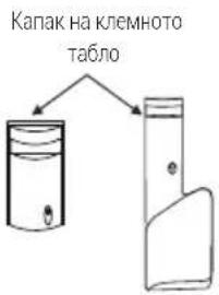
220V:
natural_image
Symbol of a trash bin crossed with no text or numbers, representing waste sorting or disposal (no text present)
(Për Ilojin e gazit R32/R290)
natural_image
Symbol of a trash bin crossed with no text or numbers, representing waste sorting or discharge (no text present)
Paralajmërim:
natural_image
Line drawing of two hands pressing down on a cylindrical object (no text or symbols)3.6 Paralajmërim specifik
natural_image
Line drawing of a hand using a power tool to clean or brush the next page of a cylindrical object (no text or symbols)5.2 Pastrojeni filtrin e ajrit
- Hiqeni filtrin e ajrit
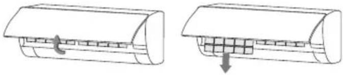
natural_image
Diagram showing two views of a car air conditioner unit with internal grid structure (no text or symbols)Fig A
natural_image
Simple line drawing of a rectangular block with an upward arrow on top (no text or symbols)Fig B
natural_image
Illustration showing a car being cleaned on a grid surface next to a bowl of laundry (no text or symbols)- Montoni filtrin
natural_image
Diagram showing two stages of a car airbag with internal components and directional arrows (no text or symbols)Fig A
natural_image
Simple line drawing of a cylindrical object with a downward arrow indicating force or direction (no text or symbols)Fig B
8.2 Pllakëza montuese
natural_image
Technical line drawing of a mechanical bracket assembly (no text or symbols)8.3 Vrima në mur
| Madhësia e tubit (mm(in)) Forca (N·m) | |
| 6/ 6,35(1/4) 15-25 | |
| 9/ 9,52(3/8) 35-40 | |
| 12/ 12,7(1/2) 45-60 | |
| 15,88(5/8) 73-78 | |
| 19,05(3/4) 75-80 |
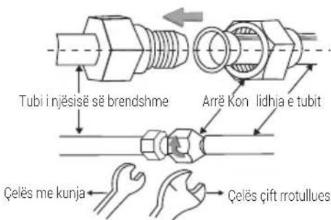
natural_image
Two-step diagram showing hand positioning and tool application on a surface, with no visible text or symbols220V:
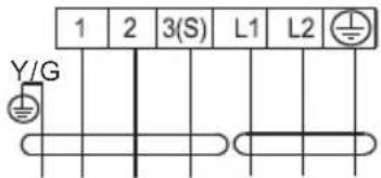
natural_image
Symbol of a trash bin crossed with two diagonal lines, representing no waste or discharge (no text or labels)
(Za vrste plina R32/R290)
natural_image
Symbol of a trash bin crossed with no text or numbers, representing waste sorting or discharge (no text present)natural_image
Line drawing of hands installing or adjusting a wall-mounted air conditioner (no text or symbols)3.6 Poseban oprez
natural_image
Line drawing of a hand using a power tool to clean or brush the next page of a cylindrical object (no text or symbols)5.2 Očistite filter za zrak
• Uklonite filter za zrak
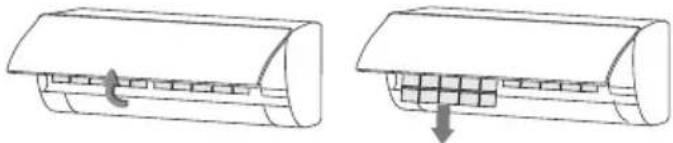
natural_image
Diagram showing two views of a car airfoil with internal grid structure, no text or symbols presentSlika A
natural_image
Simple line drawing of a rectangular block with an upward arrow on top (no text or symbols)Slika B
natural_image
Illustration showing a car being cleaned on a grid surface next to a bowl of laundry (no text or symbols)- Montirajte filter
Ponovo instalirajte osušeni filter obrnutim redoslijedom od uklanjanja, a zatim poklopite i zaključajte ploču.
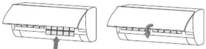
natural_image
Diagram showing two views of a car air conditioner unit with internal components and a handle (no text or symbols)Slika A
natural_image
Simple line drawing of a cylindrical object with a downward arrow indicating force or compression (no text or symbols)Slika B
natural_image
Technical line drawing of a mechanical bracket assembly (no text or symbols)8.3 Rupa u zidu
-
Električnim čekićem ili bušilicom za vodu napravite rupu za cjevovod na prethodno određenom mjestu na zidu, koja treba nagnuti prema vani pod uglom od 5°-10°.
-
Za zaštitu cjevovoda i kablova koji prolaze kroz zid od oštećenja, te od glodara koji se mogu nastaniti u šupljem zidu, potrebno je postaviti zaštitni prsten za cijevi i zabrtviti ga kitom.
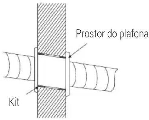

Napomena:
Obično je rupa u zidu promjera Φ 60 mm\~Φ 80 mm. Izbjegavajte prethodno ukopanu žicu za napajanje i tvrdi zid kada pravite rupu.
| Veličina cijevi (mm(in)) Moment (N·m) | |
| 6/ 6,35 (1/4) 15-25 | |
| 9/ 9,52 (3/8) 35-40 | |
| 12/ 12,7 (1/2) 45-60 | |
| 15,88 (5/8) 73-78 | |
| 19,05 (3/4) 75-80 | |
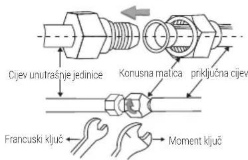

Važna napomena:
natural_image
Two-step diagram showing hand positioning and tool path, no text or symbols present8.8 Instalacija kabla za povezivanje
- Povežite kabl za povezivanje unutrašnje jedinice
-
Otvorite ploču, uklonite vijak na poklopcu ožičenja, a zatim skinite poklopac.
-
Neka kabl za povezivanje prođe kroz otvor za ukrštene kablove sa zadnje strane unutrašnje jedinice, a zatim ga izvucite sa prednje strane. (Neki modeli nemaju signalni kabl.)
- Uklonite žičanu spojnicu; spojite kabl za povezivanje na terminal ožičenja prema dijagramu ožičenja; zategnite vijak, a zatim pričvrstite kabl za povezivanje pomoću žičane spojnice.
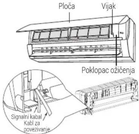

Napomena:
- Ovaj priručnik obično sadrži način ožičenja za različite vrste klima uređaja. Ne možemo isključiti mogućnost da neki posebni tip dijagrama ožičenja nije sadržan.
- Dijagram služi samo kao referenca. Ako se entitet razlikuje od ovog dijagrama ožičenja, pogledajte detaljni dijagram ožičenja koji se nalazi na jedinici koju ste kupili.
220V:
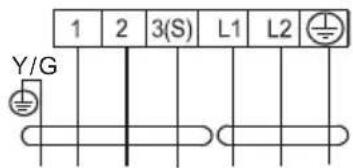
Do napajanja Do napajanja Do napajanja Do unutrašnje jedinice Do unutrašnje jedinice Do unutrašnje jedinice
Konektor

Ako postoji konektor, povežite ga direktno.

Napomena:
- Ovaj priručnik obično sadrži način ožičenja za različite vrste klima uređaja. Ne možemo isključiti mogućnost da neki posebni tip dijagrama ožičenja nije sadržan.
- Dijagram služi samo kao referenca. Ako se entitet razlikuje od ovog dijagrama ožičenja, pogledajte detaljni dijagram ožičenja koji se nalazi na jedinici koju ste kupili.
natural_image
Symbol of a trash bin with crossed lines indicating no waste or discharge, and a solid black rectangle below (no text or labels)Ovaj simbol ukazuje da na to da se ovaj proizvod ne smije odlagati s drugim kućnim otpadom na kraju njegovog vijeka trajanja. Korišteni uređaj se mora odnijeti do službene lokacije za prikupljanje radi recikliranja električnih i elektronskih uređaja. Da biste pronašli ove sisteme za prikupljanje kontaktirajte lokalne vlasti ili trgovca kod kojeg je proizvod kupljen. Svako domaćinstvo ima važnu ulogu u obnavljanju i recikliranju starih uređaja. Prikladno odlaganje korištenih uređaja pomaže u sprječavanju potencijalnih negativni posljedica po okoliš i zdravlje ljudi.
13 Uputstvo za F-plin
Ovaj proizvod sadrži fluorirane stakleničke plinove.
Fluorirani staklenički plinovi nalaze se u hermetički zatvorenoj opremi.
Instaliranje, servisiranje, održavanje, popravke, provjere curenja ili prekid rada opreme i recikliranje proizvoda trebaju obavljati fizička lica koja posjeduju odgovarajuće certifikate.
Ako sistem ima instaliran sistem za detekciju curenja, provjere curenja treba da se obavljaju najmanje svakih 12 meseci, uvjerite se da sistem ispravno radi.
Ako se na proizvodu moraju izvršiti provjere curenja, treba navesti ciklus pregleda, uspostaviti i sačuvati zapise o provjerama curenja.

Napomena: Za heremtički zatvorenu opremu, lokalni klima uređaj, prozor klima uređaja i odvlaživač, ako je CO₂ ekvivalent fluoriranih stakleničkih plinova manji od 10 tona, nije potrebno vršiti provjere na curenje.
14 Specifikacije
| Naziv modela | Unutrašnja jedinica | BEVPMS 090 | BEVPMS 120 BE | BEVPMS 180 BE | BEVPMS 240 |
| Vanjska jedinica | BEVPMS 091 | BEVPMS 121 BE | BEVPMS 181 BE | BEVPMS 241 | |
| Rashladno sredstvo R32 R32 R32 R32 | |||||
| Ukupna količina rashladnog medija (g) 5 | 50 600 1030 1300 | ||||
| Potencijal globalnog zagrijavanja (GWP) | 675 675 675 675 | ||||
| CO2 ekvivalent (tone) 0,371 0,405 0,695 | 0,878 | ||||
| Anti-električni Klasa I Klasa I Klasa I Klasa I | |||||
| Klimatska klasa T1 T1 T1 T1 | |||||
| Tip grijanja | Toplotna pumpa | Toplotna pumpa | Toplotna pumpa | Toplotna pumpa | |
| Priključak za napajanje | Vanjska | Vanjska | Vanjska | Vanjska | |
| Kapacitet hlađenja (Btu/h) [EN 14511-2] | 9212 | 11942 | 18425 | 22860 | |
| Podesivi raspon kapaciteta hlađenja (Btu/h)[EN 14511-2] | 2047-13648 | 4436-19790 | 4436-20131 | 6142-25249 | |
| Kapacitet grijanja (Btu/h)[EN 14511-2] | 8189 | 9212 | 15685 | 18083 | |
| Podesivi raspon kapaciteta grijanja (Btu/h)[EN 14511-2] | 2730-14330 | 3412-14331 | 4436-20472 | 6142-25249 | |
| Pdizajn C (kW) | 2,7 | 3,5 | 5,4 | 6,7 | |
| Pdizajn H (kW) | 2,4 (prosjek)/2,6 (toplije) | 2,7 (prosjek)/3,4 (toplije) | 4,6 (prosjek)/5,0 (toplije) | 5,3 (prosjek)/7,2 (toplije) | |
| SEER/AEER/Težina EER (W/W) 7,5 (SEER) | 7,0 (sezonski odnos energetske efikasnosti - SEER) | 7,0 (sezonski odnos energetske efikasnosti - SEER) | 6,5 (sezonski odnos energetske efikasnosti - SEER) | ||
14 Specifikacije
| Naziv modela | Unutrašnja jedinica | BEVPMS 090 | BEVPMS 120 BEVPMS 180 BEVPMS 240 | ||
| Vanjska jedinica | BEVPMS 091 | BEVPMS 121 BEVPMS 181 BEVPMS 241 | |||
| SCOP/ACOP/Težina EER (W/W) | 4,2 (sezonski koeficijent učinkovitosti - SCOP, prosjek)/5,3 (sezonski koeficijent učinkovitosti - SCOP, toplije) | 4,1 (sezonski koeficijent učinkovitosti - SCOP, prosjek)/5,1 (sezonski koeficijent učinkovitosti - SCOP, toplije) | 4,1 (sezonski koeficijent učinkovitosti - SCOP, prosjek)/5,3 (sezonski koeficijent učinkovitosti - SCOP, toplije) | 4,2 (sezonski koeficijent učinkovitosti - SCOP, prosjek)/5,4 (sezonski koeficijent učinkovitosti - SCOP, toplije) | |
| Energetski nivo-hlađenje A++ (EU) A++ (EU) A++ (EU) | |||||
| Energetski nivo-grijanje | A+ (prosjek)/A+++ (toplije) | A+ (prosjek)/A+++ (toplije) | A+ (prosjek)/A+++ (toplije) | A+ (prosjek)/A+++ (toplije) | |
| Godišnja potrošnja energije-hlađenje (kWh) | 126 163 270 340 | ||||
| Godišnja potrošnja energije-grijanje (kWh) | 800 (prosjek)/687 (toplije) | 922 (prosjek)/934 (toplije) | 1571 (prosjek)/1321 (toplije) | 1767 (prosjek)/1867 (toplije) | |
| Deklarisani kapacitet za proračun SCOP-a u dizajniranim referentnim uslovima (kW) | / / / / | ||||
| Rezervni kapacitet grijanja pretpostavljen za proračun SCOP-a u dizajniranom referentnom stanju (kW) | / / / / | ||||
| Snaga električnog grijača (W) / / / / | |||||
| Ulaz snage hlađenja (W) 630 728 1240 1425 | |||||
| Ulaz snage grijanja (W) 1049 | |||||
| Napon/frekvencija (V/Hz) | 220-240 V~/50 HZ/1 Ph | 220-240 V~/50 HZ/1 Ph | 220-240 V~/50 HZ/1 Ph | 220-240 V~/50 HZ/1 Ph | |
| Radna struja hlađenja (A) | 3,7 | 5,8 | 7,8 | 10,3 | |
| Radna struja grijanja (A) | 3,0 | 3,5 | 5,7 | 6,6 | |
| Nivo pritiska buke - unutrašnja jedinica (dBA) | 53/48/44/42/29 | 53/48/44/42/29 | 58/52/48/46/31 | 63/57/52/50/35 | |
| Nivo pritiska buke - vanjska jedinica (dBA) | 62/56//51/49/34 | 62/56//51/49/34 | 62/56//51/49/34 | 66/59/55/52/36 | |
14 Specifikacije
| Naziv modela | Unutrašnja jedinica | BEVPMS 090 | BEVPMS 120 BE | BEVPMS 180 BE | BEVPMS 240 |
| Vanjska jedinica | BEVPMS 091 | BEVPMS 121 BE | BEVPMS 181 BE | BEVPMS 241 | |
| Zapremina protoka zraka (m3/h) | 650/570/515/460 | 650/570/520/470 | 900/750/650 | 900/800/750/650 | |
| Nazivna ulazna snaga - EN 60335(W) 1600 1600 1650 3400 | |||||
| Nazivna ulazna struja - EN 60335(A) 9 9,5 12 16 | |||||
| Klasa otpora unutrašnje jedinice / / / / | |||||
| Klasa otpora vanjske jedinice IPX4 IPX4 | IPX4 IPX4 | ||||
| Prečnik cijevi visokog pritiska (mm) | 6,35(1/4") | 6,35(1/4") | 6,35(1/4") | 6,35(1/4") | |
| Promjer cijevi niskog pritiska (mm) | 9,52 (3/8") | 9,52 (3/8") | 12,7 (1/2") | 15,88 (5/8") | |
| Specifikacija kabla za napajanje ( mm^2 ) | 4G*1,5 | 4G*1,5 | 4G*1,5 | 3G*2,5 | |
| Unutrašnji i vanjski spojni kabl ( mm^2 ) | 4G*1,0 | 4G*1,0 | 4G*1,5 | 4G*2,5 | |
| Maks. dizanje (m) | 10 10 10 | 10 | |||
| Maks. dužina cijevi (m) | 20 20 20 | 20 | |||
| Dodatna količina plina (g/m) | 20 20 20 | 20 | |||
| Unutrašnja jedinica (WxHxD) mm | 768×299×201 | 768×299×201 | 997×320×222 | 1140×332×230 | |
| Vanjska jedinica (WxHxD) mm | 780×530×310 | 780×530×310 | 865×548×355 | 973×695×390 | |
| Neto težina unutrašnje jedinice (kg) | 7,5 | 8 | 11,5 | 13,5 | |
| Neto težina vanjske jedinice (kg) | 23 23 28 | 39 | |||
Napomena:
- Specifikacije su standardne vrijednosti izračunate na osnovu nominalnih radnih uslova, razlikuju se u različitim uslovima rada.
- Naša kompanija ima brza tehnička poboljšanja. Za svaku promjenu tehničkih podataka bit ćete prethodno obavješteni. Pročitajte natpisnu ploču na klima uređaju.
Pogledajte detaljne informacije o proizvodu koje se zahtijevaju u Propisu br. 206/2012 iz brošure o opisu proizvoda.
14 Specifikacije
| Naziv modela | Unutrašnja jedinica | BIHPM 090 | BIHPM 120 | BIHPM 180 | BIHPM 240 |
| Vanjska jedinica B | BIHPM 091 | BIHPM 121 | BIHPM 181 | BIHPM 241 | |
| Rashladno sredstvo R32 R32 R32 | |||||
| Ukupna količina rashladnog medija (g) 550 600 1030 1300 | |||||
| Potencijal globalnog zagrijavanja (GWP) 675 675 675 675 | |||||
| CO2 ekvivalent (tone) 0,371 0,405 0,695 0,878 | |||||
| Anti-električni Klasa I Klasa I Klasa I Klasa I | |||||
| Klimatska klasa T1 T1 T1 T1 | |||||
| Tip grijanja | Toplotna pumpa | Toplotna pumpa | Toplotna pumpa | Toplotna pumpa | |
| Priključak za napajanje | Vanjska | Vanjska | Vanjska | Vanjska | |
| Kapacitet hlađenja (Btu/h)[EN 14511-2] | 9212 | 11942 | 18425 | 22860 | |
| Podesivi raspon kapaciteta hlađenja (Btu/h)[EN 14511-2] | 2047-13648 | 4436-19790 | 4436-20131 | 6142-25249 | |
| Kapacitet grijanja (Btu/h)[EN 14511-2] | 8189 | 9212 | 15685 | 18083 | |
| Podesivi raspon kapaciteta grijanja (Btu/h)[EN 14511-2] | 2730-14330 | 3412-14331 | 4436-20472 | 6142-25249 | |
| Pdizajn C (kW) | 2,7 | 3,5 | 5,4 | 6,7 | |
| Pdizajn H (kW) | 2,4 (prosjek)/2,6 (toplije) | 2,7 (prosjek)/3,4 (toplije) | 4,6 (prosjek)/5,0 (toplije) | 5,3 (prosjek)/7,2 (toplije) | |
| SEER/AEER/Težina EER (W/W) | 7,5 (SEER) | 7,0(sezonski odnos energetske efikasnosti - SEER) | 7,0(sezonski odnos energetske efikasnosti - SEER) | 6,5(sezonski odnos energetske efikasnosti - SEER) | |
| SCOP/ACOP/Težina EER (W/W) | 4,2 (sezonski koeficijent učinkovitosti - SCOP, prosjek)/5,3 (sezonski koeficijent učinkovitosti - SCOP, toplije) | 4,1 (sezonski koeficijent učinkovitosti - SCOP, prosjek)/5,1 (sezonski koeficijent učinkovitosti - SCOP, toplije) | 4,1 (sezonski koeficijent učinkovitosti - SCOP, prosjek)/5,3 (sezonski koeficijent učinkovitosti - SCOP, toplije) | 4,2 (sezonski koeficijent učinkovitosti - SCOP, prosjek)/5,4 (sezonski koeficijent učinkovitosti - SCOP, toplije) | |
14 Specifikacije
| Naziv modela | Unutrašnja jedinica | BIHPM 090 | BIHPM 120 BIHPM 180 BIHPM 240 | ||
| Vanjska jedinica | BIHPM 091 BIHPM 121 BIHPM 181 BIHPM 241 | ||||
| Energetski nivo-hlađenje A++ (EU) A++ (EU) A++ (EU) | |||||
| Energetski nivo-grijanje | A+ (prosjek)/A+++ (toplije) | A+ (prosjek)/A+++ (toplije) | A+ (prosjek)/A+++ (toplije) | A+ (prosjek)/A+++ (toplije) | |
| Godišnja potrošnja energije-hlađenje (kWh) | 126 163 270 340 | ||||
| Godišnja potrošnja energije-grijanje (kWh) | 800 (prosjek)/687 (toplije) | 922 (prosjek)/934 (toplije) | 1571 (prosjek)/1321 (toplije) | 1767 (prosjek)/1867 (toplije) | |
| Deklarisani kapacitet za proračun SCOP-a u dizajniranim referentnim uslovima (kW) | / / / / | ||||
| Rezervni kapacitet grijanja pretpostavljen za proračun SCOP-a u dizajniranim referentnom stanju (kW) | / / / / | ||||
| Snaga električnog grijača (W) / / / / | |||||
| Ulaz snage hlađenja (W) 630 728 1240 1425 | |||||
| Ulaz snage grijanja (W) 1049 | |||||
| Napon/frekvencija (V/Hz) | 220-240 V~/50 HZ/1 Ph | 220-240 V~/50 HZ/1 Ph | 220-240 V~/50 HZ/1 Ph | 220-240 V~/50 HZ/1 Ph | |
| Radna struja hlađenja (A) 3,7 5,8 7,8 10,3 | |||||
| Radna struja grijanja (A) 3,0 3,5 5,7 6,6 | |||||
| Nivo pritiska buke - unutrašnja jedinica (dBA) | 53/48/44/42/29 53/48/44/42/29 58/52/48/46/31 63/57/52/50/35 | ||||
| Nivo pritiska buke - vanjska jedinica (dBA) | 62/56//51/49/34 | 62/56//51/49/34 | 62/56//51/49/34 | 66/59/55/52/36 | |
| Zapremina protoka zraka (m3/h) | 650/570/515/460 | 650/570/520/470 | 900/800/750/650 | 900/800/750/650 | |
| Nazivna ulazna snaga - EN 60335(W) | 1600 1600 1650 3400 | ||||
| Nazivna ulazna struja - EN 60335(A) | 9 | 9,5 | 12 | 16 | |
| Klasa otpora unutrašnje jedinice | / / / / | ||||
14 Specifikacije
| Naziv modela | Unutrašnja jedinica | BIHPM 090 | BIHPM 120 | BIHPM 180 | BIHPM 240 |
| Vanjska jedinica | BIHPM 091 | BIHPM 121 | BIHPM 181 | BIHPM 241 | |
| Klasa otpora vanjske jedinice IPX4 IPX4 IPX4 IPX4 | |||||
| Prečnik cijevi visokog pritiska (mm) | 6,35(1/4") | 6,35(1/4") | 6,35(1/4") | 6,35(1/4") | |
| Promjer cijevi niskog pritiska (mm) 9,52 (3/8") 9,52 (3/8") 12,7 (1/2") | 15,88(5/8") | ||||
| Specifikacija kabla za napajanje ( mm^2 ) 4G*1,5 4G*1,5 4G*1,5 3G*2,5 | |||||
| Unutrašnji i vanjski spojni kabl ( mm^2 ) 4G*1,0 4G*1,0 4G*1,5 4G*2,5 | |||||
| Maks. dizanje (m) 10 10 10 10 | |||||
| Maks. dužina cijevi (m) 20 20 20 20 | |||||
| Dodatna količina plina (g/m) 20 20 20 20 | |||||
| Unutrašnja jedinica (WxHxD) mm | 768×299×201 | 768×299×201 | 997×320×222 | 1140×332×230 | |
| Vanjska jedinica (WxHxD) mm | 780×530×310 | 780×530×310 | 865×548×355 | 973×695×390 | |
| Neto težina unutrašnje jedinice (kg) | 7,5 | 8 | 11,5 | 13,5 | |
| Neto težina vanjske jedinice (kg) | 23 23 28 | 39 | |||
Napomena:
- Specifikacije su standardne vrijednosti izračunate na osnovu nominalnih radnih uslova, razlikuju se u različitim uslovima rada.
- Naša kompanija ima brza tehnička poboljšanja. Za svaku promjenu tehničkih podataka bit ćete prethodno obavješteni. Pročitajte natpisnu ploču na klima uređaju.
Pogledajte detaljne informacije o proizvodu koje se zahtijevaju u Propisu br. 206/2012 iz brošure o opisu proizvoda.
Prvo pročitajte ovo korisničko uputstvo!
Poštovani korisniče,
Hvala vam što ste odabrali Bekov proizvod. Nadamo se da ćete od ovog proizvoda, proizvedenog najsavremenijom visokokvalitetnom tehnologijom, dobiti najbolje moguće performanse. Stoga vas molimo da pažljivo pročitate ovo uputstvo i sva ostala prateća dokumenta u celosti, pre korišćenja proizvoda, i sačuvajte ih da biste mogli da ih konsultujete u budućnosti. Ako proizvod dajete nekom drugom, dajte im i ovo korisničko uputstvo. Pridržavajte se svih upozorenja i smernica iz ovog korisničkog uputstva.
Značenja simbola
natural_image
Warning symbol of a flame inside a triangle (no text or numbers)(za gas tipa R32/R290)
Ovaj simbol označava da ovaj uređaj koristi zapaljivo rashladno sredstvo. Ako rashladno sredstvo procuri i dođe u kontakt sa spoljnim izvorom paljenja može doći do požara.
SADRŽAJ
1 Upozorenje 226
2 Mere opreza 231
natural_image
Symbol of a trash bin crossed with two diagonal lines, no text or numbers present
Upozorenje:
natural_image
Line drawing of hands installing or adjusting a wall-mounted air conditioner (no text or symbols)3.6 Poseban oprez
natural_image
Line drawing of a hand using a power tool to clean or brush the next page of a cylindrical object (no text or symbols)5.2 Očistite filter za vazduh
• Uklonite filter za vazduh
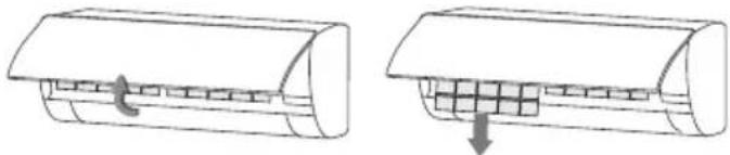
natural_image
Diagram showing two views of a car airfoil with internal grid structure (no text or symbols)Slika A
- Koristite obe ruke da biste otvorili panel do određenog ugla, sa obe strane panela, u skladu sa smerom strelice.
- Oslobodite filter za vazduh iz otvora i izvadite ga.
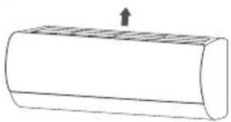
natural_image
Simple line drawing of a cylinder with an upward arrow on top surface (no text or symbols)Slika B
natural_image
Illustration showing a car being cleaned on a grid surface next to a bowl of laundry (no text or symbols)- Postavite filter
Ponovo postavite osušeni filter redosledom obrnutim od uklanjanja, a zatim zaklopite i zaključajte panel.
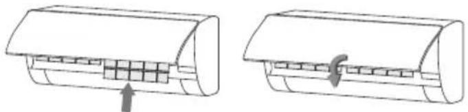
natural_image
Diagram showing two views of a car air conditioner unit with internal components and a handle (no text or symbols)Slika A
Ponovo postavite osušeni filter redosledom obrnutim od uklanjanja.
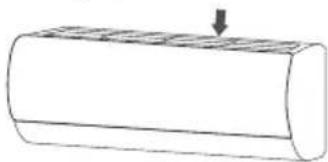
natural_image
Simple line drawing of a cylindrical object with a downward arrow indicating force or direction (no text or symbols)Slika B
5.3 Proverite pre upotrebe
- Proverite da li su svi ulazi i izlazi za vazduh na jedinicama deblokirani.
- Proverite da li postoji začepljenje na izlazu za vodu odvodne cevi i odmah ga očistite ako postoji.
- Proverite da li je žica za uzemljenje ispravno uzemljena.
- Proverite da li su baterije daljinskog upravljača postavljene i da li su dovoljno napunjene.
- Proverite da li ima oštećenja na montažnom nosaču spoljne jedinice i ako ih ima, kontaktirajte naš lokalni servisni centar.
5.4 Održavajte nakon upotrebe
- Iskopčajte izvor napajanja klima uređaja, isključite glavni prekidač i izvadite baterije iz daljinskog upravljača.
- Očistite filter i telo jedinice.
- Uklonite prašinu i prljavštinu sa spoljne jedinice.
- Proverite da li ima oštećenja na montažnom nosaču spoljne jedinice i ako ih ima, kontaktirajte naš lokalni servisni centar.
natural_image
Technical line drawing of a mechanical bracket assembly (no text or symbols)8.3 Rupa kroz zid
-
Električnim čekićem ili vodenom bušilicom napravite rupu na unapred određenom mestu na zidu za cevi, koja će biti nagnuta ka spolja za 5°–10°.
-
Radi zaštite cevi i kablova koji prolaze kroz zid od oštećenja i od glodara koji se mogu nastaniti u šupljem zidu, potrebno je postaviti zaštitni prsten cevi i izvršiti zaptivanje kitom.
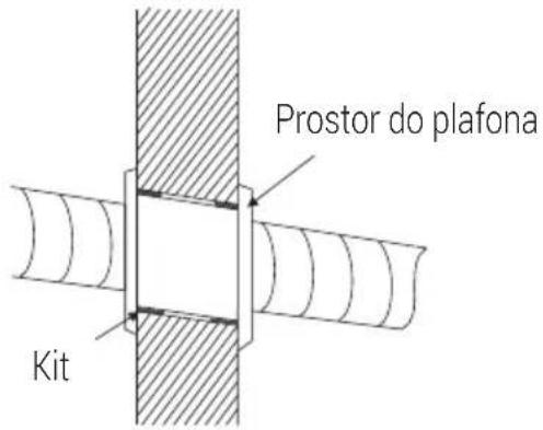

Napomena:
Rupa u zidu je obično ∅60 mm\~∅80 mm. Izbegnite prethodno ugrađenu žicu od napajanja i tvrde zidove kada pravite rupu.
| Veličina cevi (mm(in)) | Obrtni moment (N·m) |
| ∅6/∅6,35 (1/4) 15–25 | |
| ∅9/∅9,52 (3/8) 35–40 | |
| ∅12/∅12,7 (1/2) 45–60 | |
| ∅15,88 (5/8) 73–78 | |
| ∅19,05 (3/4) 75–80 |
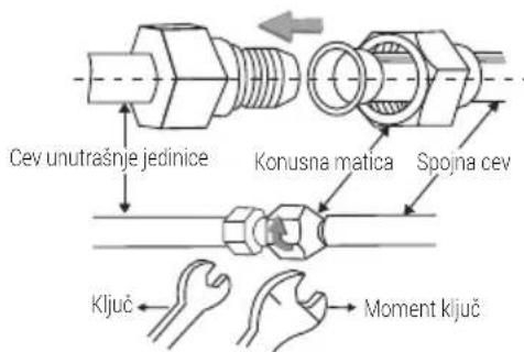

Važna napomena:
Ako je jedinica sa brzim konektorima, pogledajte uputstvo „Ugradnja spojne cevi (jedinica sa brzim konektorima)“.
8.6 Obmotajte cevi
- Koristite izolacionu navlaku da biste omotali spojni deo unutrašnje jedinice i spojne cevi, a zatim koristite izolacioni materijal da biste upakovali i obavili zaptivanje izolacione cevi, kako biste sprečili nakupljanje kondenzata na spoju.
- Povežite izlaz za vodu sa odvodnim cevima, a spojnu cev, kablove i odvodno crevo postavite pravo.
- Koristite plastične vezice za kablove da biste obmotali spojne cevi, kablove i odvodno crevo. Postavite crevo nagnuto nadole.
natural_image
Two-step diagram showing hand positioning and tool application on a mechanical component (no text or symbols)9 Ugradnja spoljne jedinice
220V:
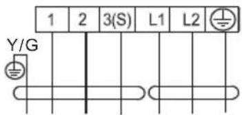
Ka napajanju Ka napajanju Ka napajanju Ka unutrašnjoj jedinici Ka unutrašnjoj jedinici Ka unutrašnjoj jedinici
Konektor

Ako postoji konektor, povežite direktno.

Napomena:
- Ovaj priručnik obično uključuje način ožičenja za različite vrste klima uređaja. Ne možemo da isključimo mogućnost da neke posebne vrste dijagrama ožičenja nisu uključene.
- Dijagram je dat samo kao referenca. Ako se jedinica razlikuje od ovog dijagrama ožičenja, pogledajte detaljnu šemu ožičenja koja se nalazi na jedinici koju ste kupili.
9 Ugradnja spoljne jedinice
9.5 Vakumiranje
9.5.1 Ekskluzivna pumpa za rashladno sredstvo R32 se mora koristiti za pravljenje vakuuma za rashladno sredstvo R32.
Pre rada na klima uređaju, skinite poklopac zapornog ventila (ventila za gas i tečnost) i obavezno ga kasnije ponovo zategnite. (da bi se sprečilo potencijalno curenje vazduha).
- Da biste sprečili curenje i prodor vazduha, zategnite sve priključne navrtke svih proširenih cevi.
- Povežite zaporni ventil, crevo za punjenje, razvodni ventil i vakuum pumpu.
- Potpuno otvorite ručicu Lo na kolektorskom ventilu i primenite vakuum najmanje 15 minuta i proverite da li složeni vakuumski manometar pokazuje -0,1 MPa (-76 cmHg).
- Nakon primene vakuuma, potpuno otvorite zaporni ventil šestougaonim ključem.
- Proverite da li su unutrašnji i spoljni priključci bez curenja vazduha.

Napomena: Jedinici sa brzim konektorima nije potrebna primena vakuuma.
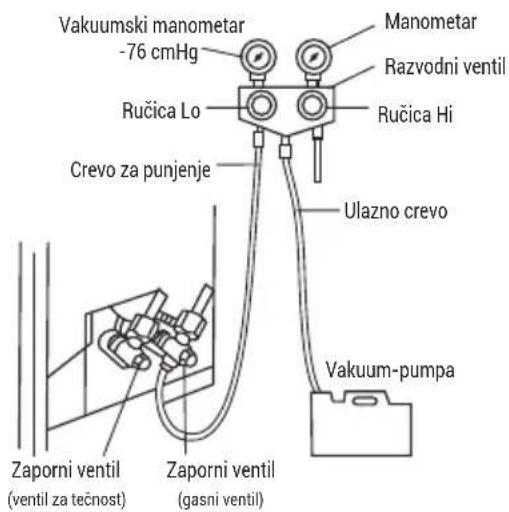
9.6 Spoljni odvod kondenzata (samo za tip sa toplotnom pumpom)
natural_image
Symbol of a trash bin with crossed lines indicating no waste or discharge, and a solid black rectangle below (no text or labels)Ovaj simbol ukazuje na to da se ovaj proizvod na kraju svog radnog veka ne sme odlagati sa ostalim otpadom iz domać instva. Uređ aj na kraju radnog veka mora se odložiti u zvanič ni sabirni centar za recikliranje električ nih i elektronskih uređ aja. Da biste našli ove sabirne centre obratite se lokalnim vlastima ili prodavcu od koga ste kupili proizvod. Svako domać instvo ima bitnu ulogu u obnavljanju i recikliranju starih uređ aja. Odgovarajuć e odlaganje uređ aja na kraju radnog veka doprinosi spreč avanju potencijalnih negativnih posledica po životnu sredinu i zdravlje.
13 Uputstvo za F-gas
natural_image
Symbol of a trash bin crossed with two crossed lines, no text or labels present
Предупредување!
natural_image
Line drawing of hands installing or adjusting a wall-mounted air conditioner (no text or symbols)natural_image
Line drawing of a hand using a power tool to clean or brush the next page of a cylindrical object (no text or symbols)natural_image
Diagram showing two views of a car air conditioner unit with cooling effect indicated by arrows (no text or symbols)Слика А
natural_image
Simple line drawing of a cylindrical object with a horizontal bar and an upward arrow, no text or symbols present.Слика Б
natural_image
Illustration showing a hand using a tape measure to clean a car on a grid surface, and a bottle of soap in a basin (no text or symbols)natural_image
Diagram showing two views of a car air conditioner unit with internal components and airflow direction (no text or symbols)Слика А
natural_image
Simple line drawing of a cylindrical object with a downward arrow indicating force or direction (no text or symbols)Слика Б
natural_image
Technical line drawing of a mechanical bracket assembly (no text or symbols)8.3 Дупка низ сид
natural_image
Two-step diagram showing hand positioning and tool positioning on a surface, with no visible text or symbols.Кон напојување
natural_image
Symbol of a trash bin crossed with no text or labels
- CONTENTS
- Please read this user manual first!
- Meanings of the symbols
- Warning 7
- Safety precautions 12
- Notices for usage 21
- Names of each part 23
- Clean and care 25
- Troubleshooting 27
- Notices for installation 30
- Installation for indoor unit 35
- Installation for outdoor unit 39
- Check after installation and test operation 43
- Maintenance Notice 44
- European disposal guidelines 49
- F-gas instruction 50
- Specifications 51
- Warning
- Note:
- FCC WARNING
- Warning:
- FCC STATEMENT
- IC STATEMENT
- Safety precautions
- WEEE Warning:
- Notices for usage
- The conditions of unit can't normally run
- Notes for heating
- Notes for turning off
- Emergency operation
- Airflow direction adjustment
- Specific caution
- Names of each part
- Indoor unit
- Clean and care
- Clean the panel
- Clean the air filter
- - Clean the Air Filter
- - Mount the Filter
- Check before using
- Maintain after using
- Troubleshooting
- Important notices:
- Unpacking Inspection
- Safety Principles for Installing Air Conditioner
- Notices for installation
- Requirements for installation position
- Installation environment inspection
- Requirements of the mounting structure
- Installation guide at the seaside
- Electrical Safety Requirements
- Requirements for operations at raised height
- Grounding Requirements
- Others
- Packing list
- Installation for indoor unit
- Dimension drawing of indoor unit installation
- Mounting plate
- Wall-through Hole
- Route of Pipeline
- Install the connection pipe
- Important note:
- Wrap the Piping
- Fixing the Indoor Unit
- Interconnection cord installation
- • After installation check
- Installation for outdoor unit
- Dimension drawing of outdoor unit installation
- Install the connection pipe
- Wiring Connection
- Wiring diagram
- Vacuuming
- Exclusive R32 refrigerant pump must be used in making R32 refrigerant vacuum.
- Outdoor condensation drainage (Heat pump type only)
- Installation:
- Check after installation and test operation
- Check after installation
- Electrical safety check
- Installation safety check
- Leak test of the refrigerant
- Test operation
- Test Operation preparation:
- Test Operation method:
- Maintenance Notice
- Qualification requirements of maintenance personnel
- Inspection of the Site
- Operating Procedures
- Inspection of Cable
- Leakage check of R32 refrigerant
- Removal and Vacuum Pumping
- Procedures of Charging Refrigerants
- Scrap and Recovery
- Scrap:
- Recovery:
- European disposal guidelines
- F-gas instruction
- Specifications
- Предупреждение:
- Отвор в стената
- Paralajmërim:
- Paralajmërim specifik
- Pastrojeni filtrin e ajrit
- - Montoni filtrin
- Pllakëza montuese
- Vrima në mur
- Poseban oprez
- Očistite filter za zrak
- - Montirajte filter
- Rupa u zidu
- Napomena:
- Važna napomena:
- Instalacija kabla za povezivanje
- Uputstvo za F-plin
- Specifikacije
- Prvo pročitajte ovo korisničko uputstvo!
- Značenja simbola
- SADRŽAJ
- Upozorenje 226
- Mere opreza 231
- Upozorenje:
- Očistite filter za vazduh
- - Postavite filter
- Proverite pre upotrebe
- Održavajte nakon upotrebe
- Rupa kroz zid
- Obmotajte cevi
- Ugradnja spoljne jedinice
- Vakumiranje
- Ekskluzivna pumpa za rashladno sredstvo R32 se mora koristiti za pravljenje vakuuma za rashladno sredstvo R32.
- Spoljni odvod kondenzata (samo za tip sa toplotnom pumpom)
- Uputstvo za F-gas
- Предупредување!
- Дупка низ сид
Brand : BEKO
Model : BEVPMS 120
Category : Air-conditioner