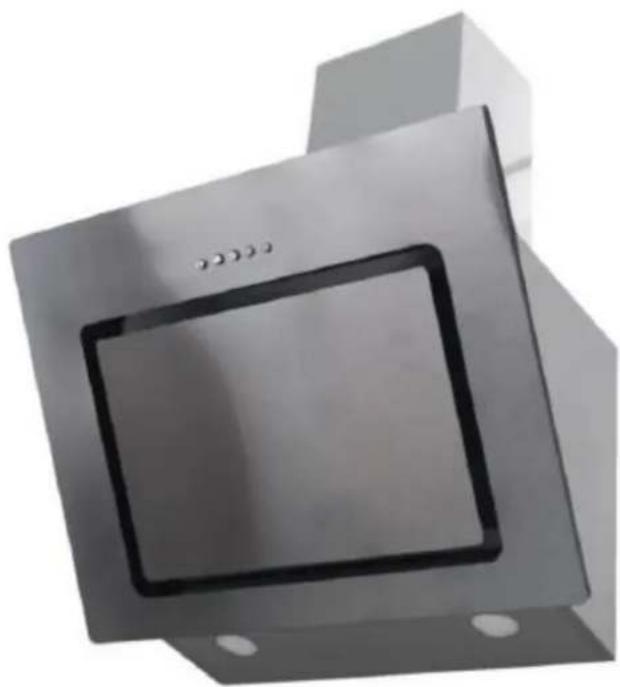
DCH-650RIX - Range hood Heinner - Free user manual and instructions
Find the device manual for free DCH-650RIX Heinner in PDF.


| Product Type | Decorative Cooker Hood |
| Brand | Heinner |
| Model | DCH-650RIX |
| Color | Stainless Steel |
| Suction Power (Max) | 586 m³/h |
| Energy Efficiency Class | A |
| Annual Energy Consumption | 22.5 kWh/year |
| Fluid Dynamic Efficiency Class | B |
| Lighting Efficiency Class | A |
| Grease Filtering Efficiency Class | D |
| Airflow (Min/Max) | 199.4 / 550.2 m³/h |
| Noise Level (Min/Max) | 50 / 70 dB(A) |
| Number of Speeds | 3 (Low, Mid, High) |
| Control Type | Push Button |
| Lighting Type | LED (2 x 2W) |
| Lighting Illuminance | 177.3 lux |
| Power Supply | AC 220-240V |
| Power Consumption (Standby) | 0.48 W |
| Power Consumption (Off) | 0 W |
| Duct Diameter | 150 mm |
| Minimum Distance (Gas Hob) | 75 cm |
| Minimum Distance (Electric Hob) | 65 cm |
| Grease Filter Material | Aluminium Mesh |
| Carbon Filter (Optional) | Not included, replace every 3-6 months |
| Warranty | Standard manufacturer warranty (details in manual) |
Frequently Asked Questions - DCH-650RIX Heinner
User questions about DCH-650RIX Heinner
0 question about this device. Answer the ones you know or ask your own.
Ask a new question about this device
Download the instructions for your Range hood in PDF format for free! Find your manual DCH-650RIX - Heinner and take your electronic device back in hand. On this page are published all the documents necessary for the use of your device. DCH-650RIX by Heinner.
USER MANUAL DCH-650RIX Heinner
natural_image
3D rendering of a metallic industrial fan or vent with a square grille and mounting holes (no text or symbols visible)• Decorative cooker hood
• Suction power: 586 m³/h
• Color: Stainless steel
Thank you for purchasing this product!
I. INTRODUCTION
Please read the instructions carefully and keep the manual for future information.
This manual is designed to give all necessary instructions concerning installation, use and maintenance of the unit. In order to operate the unit correctly and safely, please read this instruction manual carefully before installation and use.
II. PACKAGE CONTENT

➢ Decorative cooker hood
User manual
Warranty card
III. SAFETY PRECAUTION
This manual explains the proper installation and use of your cooker hood, please read it carefully before using even if you are familiar with the product. The manual should be kept in a safe place for future reference.
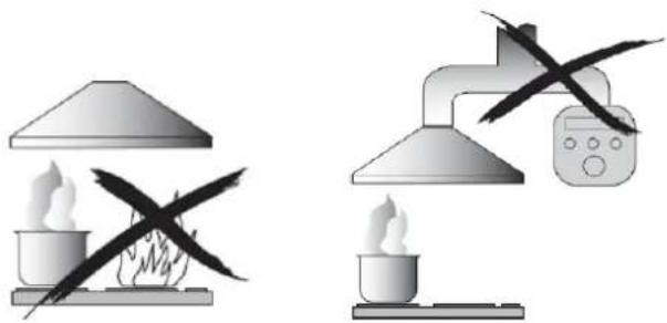
NEVER TO DO:
- Do not try to use the cooker hood without the grease filters or if the filters are excessively greasy!
- Do not install above a cooker with a high-level grill.
- Do not leave frying pans unattended during use because overheated fats or oils might catch fire.
- Never leave naked flames under the cooker hood.
- If the cooker hood is damaged, do not attempt to use.
- Do not flambé under the cooker hood.
- CAUTION: Accessible parts may become hot when used with cooking appliances.
- The minimum distance between the supporting surface for the cooking vessels on the hob and the lowest part of the cooker hood. (When the cooker hood is located above a gas appliance, this distance shall be at least 65 cm)
- The air must not be discharged into a flue that is used for exhausting fumes from appliances burning gas or other fuels.
natural_image
Two experimental setups: one with a lamp and fire extinguisher, the other with a lamp and a digital device (no text or symbols)ALWAYS TO DO:
- Important! Always switch off the electricity supply at the mains during installation and maintenance such as light bulb replacement.
- The cooker hood must be installed in accordance with the installation instructions and all measurements followed.
- All installation work must be carried out by a competent person or qualified electrician.
- Please dispose of the packing material carefully. Children are vulnerable to it.
- Pay attention to the sharp edges inside the cooker hood especially during installation and cleaning.
- When the cooker hood is located above a gas appliance, the minimum distance between the supporting surface for the cooking vessels on the hob and the lowest part of the cooker hood that distance must be:
Gas cookers: 75 cm
Electric cookers: 65 cm
Coal or oil cookers: 75 cm
- Make sure the ducting has no bends sharper than 90 degrees as this will reduce the efficiency of the cooker hood.
- Warning: Failure to install the screws or fixing device in accordance with these instructions may result in electrical hazards.
• Always put lids on pots and pans when cooking on a gas cooker.
- When in extraction mode, air in the room is being removed by the cooker hood.
- Please make sure that proper ventilation measures are being observed. The cooker hood removes odours from room but not steam.
• Cooker hood is for domestic use only.
- If the supply cord is damaged, it must be replaced by the manufacturer, its service agent or similarly qualified persons in order to avoid a hazard.
- This appliance can be used by children aged from 8 years and above and persons with reduced physical, sensory or mental capabilities or lack of experience and knowledge if they have been given supervision or instruction concerning use of the appliance in a safe way and understand the hazards involved. Children shall not play with the appliance. Cleaning and user maintenance shall not be made by children without supervision.
- Caution: The appliance and its accessible parts can become hot during operation. Be careful to avoid touching the heating elements. Children younger than 8 years old should stay away unless they are under permanent supervision.
- There shall be adequate ventilation of the room when the cooker hood is used at the same time as appliances burning gas or other fuels.
There is a fire risk if cleaning is not carried out in accordance with the instructions
- Regulations concerning the discharge of air have to be fulfilled.
- Clean your appliance periodically by following the method given in the chapter MAINTENANCE.
- For safety reason, please use only the same size of fixing or mounting screw which are recommended in this instruction manual.
- Regarding the details about the method and frequency of cleaning, please refer to maintenance and cleaning section in the instruction manual.
- Cleaning and user maintenance shall not be made by children without supervision. When the cooker hood and appliances supplied with energy other than electricity are simultaneously in operation, the negative pressure in the room must not exceed 4 Pa (4 x 10⁻⁵ bar).
IV. INSTALLATION INSTRUCTIONS (VENT OUTSIDE)
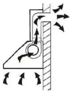
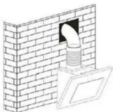
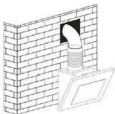
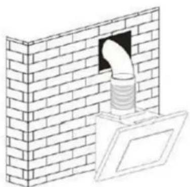
If you have an outlet to the outside, your cooker hood can be connected as below picture by means of an extractions duct (enamel, aluminum, flexible pipe or inflammable material with an interior diameter of 150mm).
natural_image
Diagram of a mechanical or fluidic system with directional arrows indicating flow or movement (no text or symbols)- Before installation, turn the unit off and unplug it from the outlet.
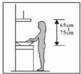
- The cooker hood should be placed at a distance of 65\~75cm above the cooking plane for best effect.
Pic1
Pic 1
- Using a drill bit with an 8mm diameter, make 8 holes in the wall at the position that you reserve for installing the chimney and cooker hood body. See Pic 2.
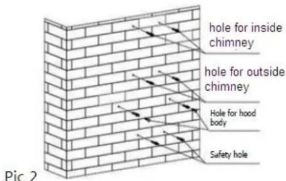
- Insert wall plugs into the holes that you have drilled for the cooker hood body, fasten 2 × support screw ST4*40 mm halfway in, leaving them 2 mm out of the wall. See Pic 2.
- Hang the cooker hood onto the support screws.
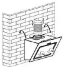
- Insert self-tap screw ST4*30 mm into the safety holes and fully fasten it to ensure the cooker hood is well fixed. See pic 3.
natural_image
Diagram of a kitchen appliance with a glass tube and water-filled stove, mounted on a brick wall (no text or symbols)Pic 3
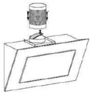
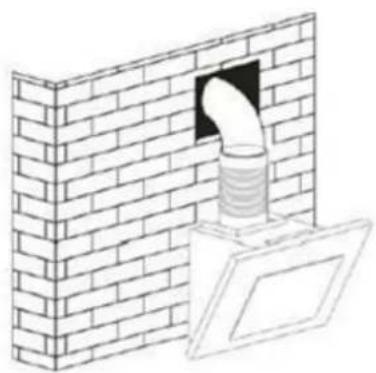
- Attach the expansion pipe on the one-way wall valve as shown below. Fix the expansion pipe on the valve by cable tie. Lift up expansion pipe till it out of the wall through the hole on the wall.
natural_image
Simple line drawing of a mechanical device with a cylindrical component mounted on a base (no text or symbols)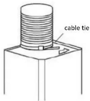
natural_image
Illustration of a brick wall with a pipe opening and a separate open door (no text or symbols)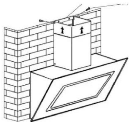
natural_image
Diagram of a brick wall with a chimney and window, showing structural components without any text or symbols.NOTE: The two safety vents are positioned on the back housing, with diameter of 6 mm.
V. MOUNTING OF THE V-FLAP
If the cooker hood does not have an assembled V-flap 1, you should mount the half-parts to the its body.
To mount the V-flap 1 you should:
- Mount two half-parts 2 into the body 6;
- a pin 3 should be top oriented;
- the axis 4 should be inserted in the holes 5 on body;
- repeat all the operations for the 2nd half-part.
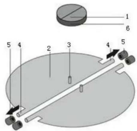
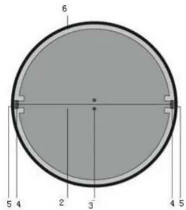
HINTS FOR EXHAUST DUCT INSTALLATION
The following rules must be strictly followed to obtain optimal air extraction:
- Keep expansion pipe short and straight.
- Do not reduce the size or restrict expansion pipe.
- When using expansion pipe always install the pipe pulled taut to minimize pressure loss.
- Failure to observe these basic instructions will reduce the performance and increase noise levels of the cooker hood.
- Any installation work must be carried out by a qualified electrician or competent person.
- Do not connect the ducting system of the hood to any existing ventilation system which is being used for any other appliance, such as warmer tube, gas tube, hot wind tube.
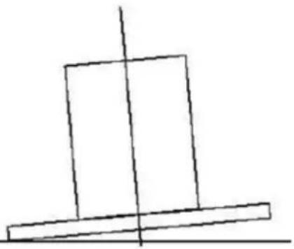
•The angle of the bend of the expansion pipe should not be less than 120^ ; you must direct the pipe horizontally, or, alternatively, the pipe should go up from the initial point and should be led to an outer wall.
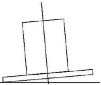
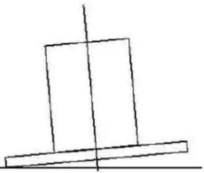
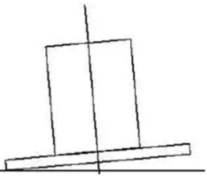
• After the installation, make sure that the cooker hood is level to avoid grease collection at on end.
- Ensure the expansion pipe selected for installation complies with relevant standards and is fire retardant.
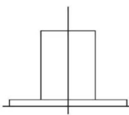
natural_image
Simple geometric diagram with a vertical line crossing a horizontal base (no text or symbols)Right
natural_image
Simple line drawing of a tilted rectangular block with a vertical centerline (no text or symbols)Wrong
WARNING:
For safety reason, please use only the same size of fixing or mounting screw which are recommended in this instruction manual.
Failure to install the screws or fixing device in accordance with these instructions may result in electrical hazards.
VI. USING THE APPLIANCE
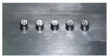
Push button
a. Press the button "STOP", the motor is stopped then.
b. Press the button "LOW", the motor is running at low speed.
c. Press the button "MID", the motor is running at medium speed.
d. Press the button "HIGH", the motor is running at high speed.
e. Press the button "LIGHT", both lights start shining. Press the button again, the lights are switched off.
natural_image
Five metallic cylindrical components arranged on a reflective surface (no visible text or symbols)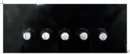
natural_image
Five circular light sources on dark background, no visible text or symbolsVII. TROUBLESHOOTING
| FAULT | POSSIBLE CAUSE | SOLUTION |
| Light on, but motor does not work | Fan switched turned off | Select a fan switch position |
| Fan switch failed | Contact service center | |
| Motor failed | Contact service center | |
| Light does not work, motor does not work | House fuses blown | Reset/Replace fuses |
| Power cord loose or disconnected | Refit cord to power outlet.Switch power outlet on. | |
| Oil leakage | One-way valve and the air ventilation entrance are not tightly sealed | Take down the one-way valve and seal with sealant. |
| Leakage from the connection of U-shaped section and cover | Take U-shaped section down and seal. | |
| Lights not working | Broken/Faulty globes | Replace globes as per this instruction. |
| Insufficient suction | The distance between the cooker hood and the gas top is too far | Refit the cooker hood to the correct distance. |
| The cooker hood inclines | The fixing screw not tight enough | Tighten the hanging screw and make it horizontal |
NOTE: Any electrical repairs to this appliance must conform to your local, state and federal laws. Please contact the service centre if in any doubt before undertaking any of the above. Always disconnect the unit from the power source when opening the unit.
VIII. CLEANING AND MAINTENANCE
CAUTION
Before maintenance or cleaning is carried out, the cooker hood should be disconnected from the main supply. Ensure that the cooker hood is switched off at the wall socket and the plug removed.
External surfaces are susceptible to scratches and abrasions, so please follow the cleaning instructions to ensure the best possible result is achieved without damage.
GENERAL
Cleaning and maintenance should be carried out with the appliance cold especially when cleaning. Avoid leaving alkaline or acid substances (lemon juice, vinegar etc.) on the surfaces.
STAINLESS STEEL
The stainless steel must be cleaned regularly (e.g. weekly) to ensure long life expectancy. Dry with a clean soft cloth. A specialized stainless-steel cleaning fluid may be used.
NOTE: Ensure that wiping is done along with the grain of the stainless steel to prevent any unsightly crisscross scratching patterns from appearing.
CONTROL PANEL SURFACE
The inlay control panel can be cleaned using warm soapy water. Ensure the cloth is clean and well wrung before cleaning. Use a dry soft cloth to remove any excess moisture left after cleaning.
IMPORTANT
Using neutral detergents and avoid using harsh cleaning chemicals, strong household detergents or products containing abrasives, as this will affect the appliance appearance and potentially remove any printing of artwork on the control panel and will void manufactures warrantee.
GREASE MESH FILTERS
The mesh filters can be cleaned by hand.
Soak them for about 3 minutes in water with a grease-loosening detergent then brush it gently with a soft brush. Please do not apply too much pressure, avoid damaging it. (Leave to dry naturally out of direct sun light)
Filters should be washed separately to crockery and kitchen utensils. it is advisable not to use rinse aid.
INSTALLING GREASE MESH FILTERS
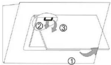
- To install filters for the following four steps.
- Angle the filter into slots at the back of the hood.
- Push the button on handle of the filter.
- Release the handle once the filter fits into a resting position.
- Repeat to install all filters.
CARBON FILTER – not included in the package
Activated carbon filter can be used to trap odors. Normally the activated carbon filter should be changed at three or six months according to your cooking habit. The installation procedure of activated carbon filter is as below.
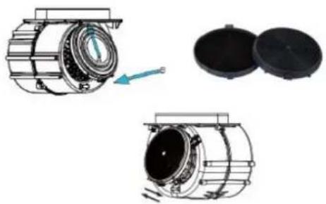
In order to install the activated carbon filter, the aluminium filter should be detached first. Firstly, open carefully the stainless-steel cover, then press the lock of aluminium filter and remove it.
- Put the pin of the carbon filter into the rectangular hole of the fan (as per the arrow A shown below)
- Push the other side of the carbon filter toward the fan to make it flat (as per the arrow B shown), and then press filter into fan.
- If you want to remove the filter, press fastener of filter and remove it by turning anticlockwise.
natural_image
Technical illustration of a mechanical component with cross-sectional views and a blue arrow indicating motion (no text or symbols)NOTE:
- Make sure the filter is securely locked. Otherwise, it would loosen and cause dangerous.
- When activated carbon filter attached, the suction power will be lowered.
BULB REPLACEMENT
- The bulb must be replaced by the manufacturer, its service agent or similarly qualified persons.
- Always switch off the electricity supply before carrying out any operations on the appliance. When handling bulb, make sure it is completely cool down before any direct contact to hands.
- When handling globes hold with a cloth or gloves to ensure perspiration does not meet the globe as this can reduce the life of the globe.
LED LIGHTS
- Switch the unit off and pull out the plug first.
- Wait until the light bulb is cooled down before replacement.
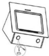
- Remove the front part with the aid of screwdriver.
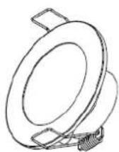
- Pull out the LED light carefully and replace with the same type and rated LED light (2*2W LSD-B1 LED light)
- Replace the front part back to the unit with screwdriver.
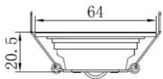
- ILCOS D code for this lamp is: DBR-2/65-H-64
- LED modules -round lamp
- Max wattage: 2 W
– Voltage range: AC 220-240V - Dimensions:
natural_image
Simple line drawing of a vintage television set with a screen and buttons, no text or symbols present.IMPORTANT
The following shows how to reduce total environmental impact (e.g. energy use) of the cooking process).
(1) Install the cooker hood in a proper place where there is efficient ventilation.
(2) Clean the cooker hood regularly so as not to block the airway.
(3) Remember to switch off the cooker hood light after cooking.
(4) Remember to switch off the cooker hood after cooking.
INFORMATION FOR DISMANTLING
Do not dismantle the appliance in a way which is not shown in the user manual. The appliance could not be dismantled by user. At the end of life, the appliance should not be disposed of with household waste. Check with you Local Authority or retainer for recycling advice.
IX. TECHNICAL FICHE
| Product fiche according to Commission Delegated Regulation (EU) No. 65/2014 | |
| Trademark | Heinner |
| Model | DCH-650RIX |
| Annual energy consumption (kWh/year) | 22.5 |
| Energy efficiency class | A |
| Fluid dynamic efficiency | 23.7 |
| Fluid dynamic efficiency class | B |
| Lighting efficiency (lux/W) | 37.7 |
| Lighting efficiency class | A |
| Grease filtering efficiency (%) | 71 |
| Grease filtering efficiency class | D |
| Airflow at minimum and maximum speed under normal conditions of use (m3/h) | 199.4/550.2 |
| Airborne acoustical A-weighted sound power emissions at minimum and maximum speed under normal conditions of use (dB(A)) | 50/70 |
| Time increase factor | 1.1 |
| Energy efficiency index | 51.1 |
| Measured airflow rate at best efficiency point (m3/h) | 198.7 |
| Measured airflow pressure at best efficiency point (Pa) | 204 |
| Measured electric power at best efficiency point (W) | 47.5 |
| Nominal power of the lighting system (W) | 4.7 |
| Average illumination of the lighting system on the cooking surface (lux) | 177.3 |
| Power consumption in standby mode (W) | 0.48 |
| Power consumption in off mode (W) | 0 |

Environment friendly disposal
You can help protect the environment!
Please remember to respect the local regulations: hand in the non-working electrical equipment's to an appropriate waste disposal center.

HEINNER is a registered trademark of Network One Distribution SRL. Other brands and product names are trademarks or registered trademarks of their respective holders.
No part of the specifications may be reproduced in any form or by any means or used to make any derivative such as translation, transformation, or adaptation without permission from NETWORK ONE DISTRIBUTION.
Copyright © 2013 Network One Distribution. All rights reserved.
www.heinner.com, http://www.nod.ro

This product is in conformity with norms and standards of European Community.
Importer: Network One Distribution
Marcel Iancu Street, no 3-5, Bucharest, Romania
Tel: +40 21 211 18 56, www.heinner.com, www.nod.ro
HEINNER
HOTĂ DECORATIVĂ
Modele: DCH-650RIX
natural_image
3D rendering of a metallic industrial cabinet or enclosure with a square opening and mounting holes (no visible text or symbols)natural_image
Two laboratory setup diagrams showing heating and cooling setups with no visible text or symbolsAVERTISMENTE:
natural_image
Diagram of a mechanical or fluidic system with directional arrows indicating flow or movement (no text or symbols)natural_image
Isometric line drawing of a brick wall with diagonal bracing (no text or symbols)natural_image
Diagram of a kitchen appliance mounted on a brick wall, showing a tray with a glass and water-filled lid (no text or symbols)Fig. 3
natural_image
Simple line drawing of a mechanical device with a cylindrical component mounted on a base (no text or symbols)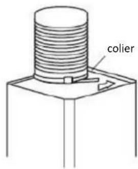
natural_image
Illustration of a brick wall with a pipe opening and a small panel attached (no text or symbols)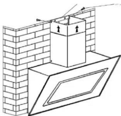
natural_image
Technical line drawing of a brick wall and ceiling structure with mounting brackets (no text or symbols)natural_image
Simple geometric diagram with a vertical line crossing a horizontal base (no text or symbols)Corect
natural_image
Simple line drawing of a tilted rectangular block with a vertical centerline (no text or symbols)Incorrect
AVERTISMENT:
natural_image
Five metallic cylindrical components arranged horizontally on a reflective surface (no text or symbols visible)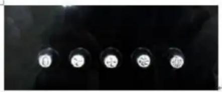
natural_image
Close-up of four metallic circular components with white centers, arranged vertically against a dark background (no text or symbols visible)VII. SOLUTIONAREA PROBLEMELOR
natural_image
Technical illustration of a mechanical component with exploded view and close-up views (no text or symbols)NOTĂ:
natural_image
Simple line drawing of a monitor with a small lock icon at the base (no text or symbols)IMPORTANT
natural_image
3D rendering of a metallic industrial fan or vent with a square grille and mounting holes (no text or symbols visible)natural_image
Two experimental setups showing heating and cooling methods with no visible text or symbolsFIGYELMEZTETÉSEK:
natural_image
Diagram of a mechanical or fluidic system with directional arrows indicating flow or movement (no text or symbols present)natural_image
Illustration of a wall-mounted kitchen appliance with a glass tube above it, mounted on a brick wall (no text or symbols)natural_image
Simple line drawing of a mechanical device with a cylindrical component mounted on a base (no text or symbols)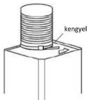
natural_image
Illustration of a brick wall with a pipe opening and a separate view of a window (no text or symbols)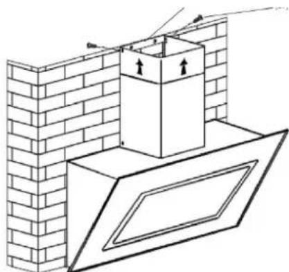
natural_image
Architectural diagram showing brick wall and window installation with a chimney (no text or symbols)natural_image
Simple geometric diagram with a vertical line crossing a horizontal base (no text or symbols)Helyes
natural_image
Simple line drawing of a tilted rectangular block with a vertical centerline (no text or symbols)Helytelen
FIGYELMEZTETÉS:
natural_image
Five metallic cylindrical components arranged on a reflective surface (no visible text or symbols)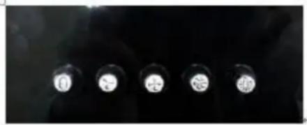
natural_image
Close-up of five circular light sources on a dark surface (no text or symbols visible)VII. HIBAELHÁRÍTÁS
natural_image
Technical illustration of a mechanical component with three views: top, side, and bottom (no text or symbols)MEGJEGYZÉS:
natural_image
Simple line drawing of a vintage television set with a screen and buttons (no text or symbols)FONTOS
natural_image
3D rendering of a metallic industrial fan or vent with a black square grille and mounting holes (no text or symbols visible)natural_image
Two experimental setups showing heating and cooling methods: one with a lamp, the other with a lamp (no text or symbols)ПРЕДУПРЕЖДЕНИЯ:
natural_image
Diagram of a mechanical or fluidic system with directional arrows indicating flow or movement (no text or symbols present)natural_image
Diagram of a brick wall with a water dispenser and a container, no text or symbols presentФиг. 3
natural_image
Simple line drawing of a mechanical device with a cylindrical component mounted on a base (no text or symbols)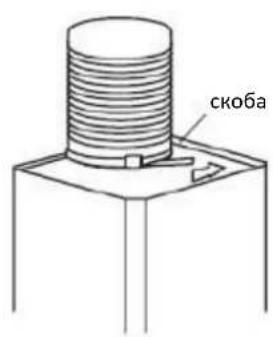
natural_image
Illustration of a brick wall with a pipe opening and a separate view of a window (no text or symbols)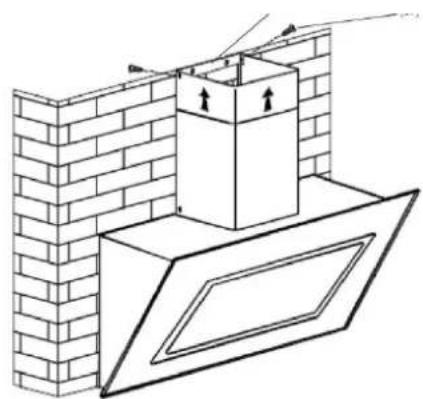
natural_image
Diagram of a brick wall with a chimney and window, showing structural details without any text or symbols.natural_image
Simple geometric diagram with a vertical line crossing a horizontal base (no text or symbols)Правилно
natural_image
Simple line drawing of a tilted rectangular block with a vertical centerline (no text or symbols)Неправил
ПРЕДУПРЕЖДЕНИЕ:
natural_image
Five metallic cylindrical components arranged horizontally on a reflective surface (no text or symbols visible)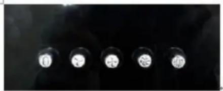
natural_image
Five identical circular light sources on a dark background, no text or symbols visibleVII. РАЗРЕШАВАНЕ НА ПРОБЛЕМИ
natural_image
Technical illustration of mechanical components with no visible text or symbolsЗАБЕЛЕЖКИ:
- Thank you for purchasing this product!
- INTRODUCTION
- PACKAGE CONTENT
- SAFETY PRECAUTION
- NEVER TO DO:
- ALWAYS TO DO:
- INSTALLATION INSTRUCTIONS (VENT OUTSIDE)
- MOUNTING OF THE V-FLAP
- HINTS FOR EXHAUST DUCT INSTALLATION
- WARNING:
- USING THE APPLIANCE
- Push button
- TROUBLESHOOTING
- CLEANING AND MAINTENANCE
- CAUTION
- GENERAL
- STAINLESS STEEL
- CONTROL PANEL SURFACE
- GREASE MESH FILTERS
- INSTALLING GREASE MESH FILTERS
- CARBON FILTER – not included in the package
- NOTE:
- BULB REPLACEMENT
- LED LIGHTS
- IMPORTANT
- INFORMATION FOR DISMANTLING
- TECHNICAL FICHE
- Environment friendly disposal
- HEINNER
- AVERTISMENTE:
- AVERTISMENT:
- SOLUTIONAREA PROBLEMELOR
- NOTĂ:
- FIGYELMEZTETÉSEK:
- FIGYELMEZTETÉS:
- HIBAELHÁRÍTÁS
- MEGJEGYZÉS:
- FONTOS
- ПРЕДУПРЕЖДЕНИЯ:
- ПРЕДУПРЕЖДЕНИЕ:
- РАЗРЕШАВАНЕ НА ПРОБЛЕМИ
- ЗАБЕЛЕЖКИ:
Brand : Heinner
Model : DCH-650RIX
Category : Range hood