CH-201SS - Range hood Heinner - Free user manual and instructions
Find the device manual for free CH-201SS Heinner in PDF.


| Product Type | Range Hood |
| Brand | Heinner |
| Model | CH-201SS |
| Mounting Type | Wall-mounted |
| Dimensions (W x D x H) | 600 x 500 x 150 mm |
| Weight | 10 kg |
| Power Supply | 220-240 V, 50 Hz |
| Maximum Extraction Rate | 600 m³/h |
| Noise Level | 55 dB |
| Lighting | LED (2 x 1W) |
| Grease Filter | Aluminum, washable |
| Number of Speeds | 3 + Intensive |
| Control Type | Push buttons |
| Energy Class | A |
| Ducted/Recirculating | Convertible |
| Annual Energy Consumption | 50 kWh |
| Grease Filter Efficiency | Class B |
| Airflow Efficiency | Class A |
| Maintenance | Clean grease filters monthly; replace charcoal filters every 3-6 months if recirculating |
| Safety Features | Thermal cut-out, auto-off |
| Spare Parts | Grease filters, charcoal filters, LED bulbs |
| Reparability | Contact authorized Heinner service centers |
Frequently Asked Questions - CH-201SS Heinner
User questions about CH-201SS Heinner
0 question about this device. Answer the ones you know or ask your own.
Ask a new question about this device
Download the instructions for your Range hood in PDF format for free! Find your manual CH-201SS - Heinner and take your electronic device back in hand. On this page are published all the documents necessary for the use of your device. CH-201SS by Heinner.
USER MANUAL CH-201SS Heinner
natural_image
Exterior view of a stainless steel kitchen ventilation cover with ventilation grilles (no text or symbols visible)- Hota traditionala
• Capacitate absorbtie: 209.7 m³/h - Culoare: inox
natural_image
Technical line drawing of a mechanical component with mounting holes and a central circular feature (no text or symbols)Pic 3
natural_image
Technical line drawing of a flatbed electronic device with two ports and a grid background (no text or symbols)Pic 4
Metoda B
Pic 5
Nota: Sunt disponibile doua moduri de ventilare: ventilare orizontala si ventilare verticala.
Va rugam sa acordati atentie metodei dorite de ventilare inainte de a alege metoda de instalare.
natural_image
Simple line drawing of a rectangular electronic component with two circular arrows indicating upward motion (no text or symbols)A
natural_image
Technical line drawing of a mechanical component with a rectangular base and circular opening, showing internal structure and downward arrows (no text or symbols)B
Pic 6
Setare ventilare
natural_image
Diagram of a rectangular electronic device with internal components and directional arrows indicating motion (no text or symbols)C
B
natural_image
Isometric view of a rectangular electronic component with mounting holes and a central slot (no text or symbols)D
Pic 7

VI. DEPANARE
natural_image
Diagram of a fan inside an air conditioner unit with cooling fins and ventilation slots (no text or symbols)INSTALAREA FILTRELOR DE GRĂSIME
NOTĂ:
natural_image
Diagram of an air conditioner unit with fan and ventilation grilles (no text or labels)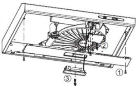
VIII. FISA TEHNICA
| Capacitate absorbtie: | 209.7 m3/h |
| Motor | 1x85W |
| Culoare: | Alb |

Copyright © 2013 Network One Distribution. All rights reserved. http://www.heinner.com, http://www.nod.ro

natural_image
Exterior view of a stainless steel kitchen ventilation cover (no text or symbols visible)• Traditional cooker hood
• Suction power: 209.7 m³/h
• Color: stainless steel
Thank you for purchasing this product!
I. INTRODUCTION
Before using the appliance, please read carefully this instruction manual and keep it for future reference.
This instruction manual is designed to provide you with all required instructions related to the installation, use and maintenance of the appliance.
In order to operate the unit correctly and safety, please read this instruction manual carefully before installation and usage.
II. CONTENT OF YOUR PACKAGE

▶ Traditional cooker hood
User manual
Warranty card
III. SAFETY PRECAUTIONS
If this product has arrived damaged please return for change or repair. DO NOT INSTALL THIS APPLANCE IF YOU FOUND IT DANAGED.
Children should be supervised to ensure that they do not play with the appliance.
This appliance is designed for domestic use only.
Any installation work must be carried out by a qualified electrician or competent person.
There is a fire risk if cleaning is not carried out in accordance with the instructions.
Details concerning the method and frequency of cleaning are stated in the section.
"INSTALLATION AND MAINTENANCE".
Do not pull on the connection cord, but rather on the plug, to separate the appliance from the mains.
When cleaning the appliance, it must be off power first.
IV. INSTALLATION
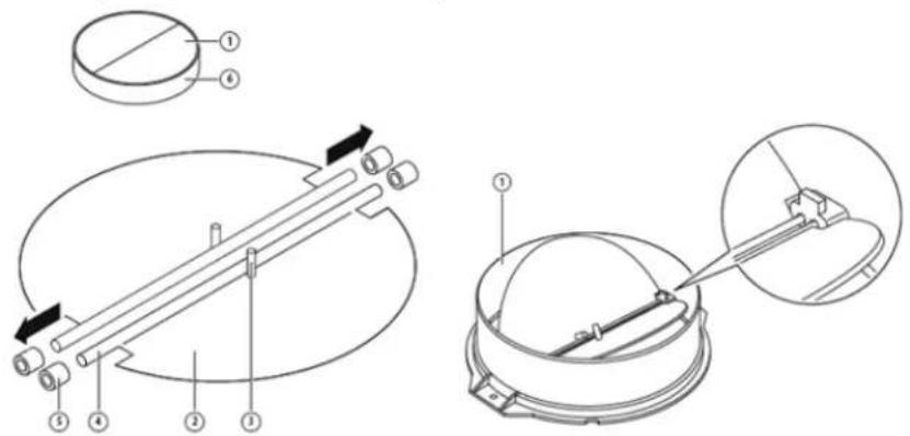
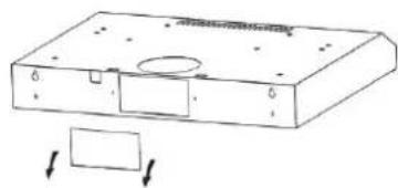
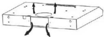
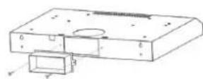
MOUNTING OF THE V-FLAP
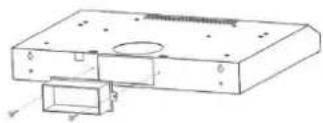
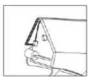
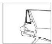
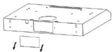
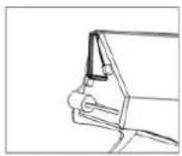
If the cooker hood does not have an assembled V-flap 1, you should mount the half-parts to its body. The images only show an example of how to mount the V-flap, the outlet may be various according to different models and configuration.
To mount the V-flap 1 you should:
- Mount two half-parts 2 into the body 6
- a pin 3 should be top oriented;
- the axis 4 should be inserted in the holes 5 on body;
- repeat all the operations for the 2nd half-part
Before installation, turn the unit off and unplug it from the outlet.
INSTALLATION
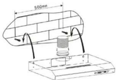
Method A
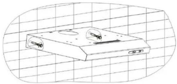
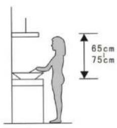
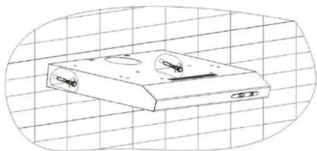
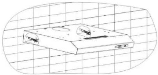
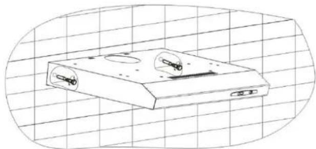
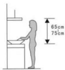
- The cooker hoods should be placed at a distance of 65-75cm from the cooking surface for best effect.
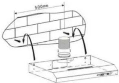
- To install onto the wall, drill 4 holes of ∅ 8mm on a suitable place according with the center distance of hole in the back of the cooker hood.
- Insert the nut into the holes.
- Insert the screws into the nuts and tight.
- Put up the cooker hood onto the fixed screws.
- Then use the attached accessories enclosed to turn the screws into the two holes of inside the hood, and then fix the screws to tighten the hood onto the wall.
- Put the one way valve onto the cooker hood.
Pic 1
Pic 2
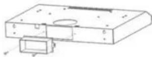
natural_image
Technical line drawing of a mechanical housing or enclosure with mounting holes and internal components (no text or symbols)Pic 3
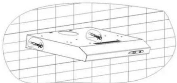
natural_image
Line drawing of a flatboard device with two circular cutouts and a base, set against a grid background (no text or symbols)Pic 4
Method B
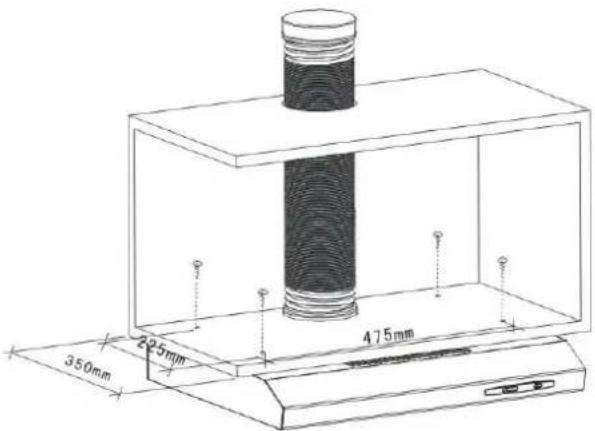
1) Drill 4 holes of ∅ 6mm at the bottom of the hanging Cup board.
2) Put the one way valve on the cooker hood, then install the cooker hood on the bottom of the cupboard, tighten the hood with enclosed 4 screws.
3) Install the adjusted board on the bottom of the hood in order to keep out the gap between hood back and cupboard.
Pic 5
Notice
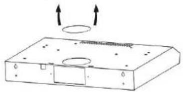
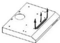
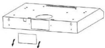
There are 2 methods for ventilation, including 'horizontal ventilation' and 'vertical ventilation'. Please pay attention to the ventilation method when installation.
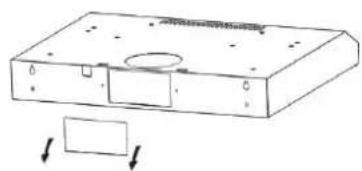
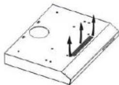
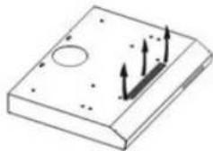
Vertical ventilation: As shown in pic 6A, please use the cover to seal the outlet on the back, then the air can be vented from top.
Horizontal ventilation: As shown in pic. 6B, please use the cover to seal the outlet on the top, then the air can be vented from back.
natural_image
Technical line drawing of a mechanical component with two circular arrows indicating upward motion (no text or symbols)A
natural_image
Technical line drawing of a mechanical housing with a rectangular component and circular opening (no text or symbols)B
Pic 6
Air ventilation setting
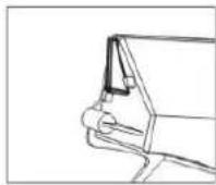
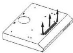
Outdoor air ventilation: Turn the adjuster to outdoor position (pic. 7A), install the outlet, turn on the cooker hood, then the air will be vented from the outside outlet (pic. 7C).
Indoor air ventilation: Turn the adjuster to indoor position (pic. B), install the outlet cover, turn on the cooker hood, then the air can be vented from the inside outlet (pic. 7D).
A
natural_image
Simple line drawing of a rectangular electronic component with internal components and directional arrows indicating motion (no text or symbols)C
B
D
Pic 7

For safety reason, please use only the same size of fixing or mounting screw which are recommended in this instruction manual.
Failure to install the screws or fixing device in accordance with these instructions may result in electrical hazards.
V. OPERATION
The switch is operated as below:
- Press stop button, the motor will stop.
- Press the button to "low", "middle" and "high", the motor will be turned on at "low", "middle" and "high" speed respectively.
- Press "light", the light will be on. Press it again, the light will be off.

VI. TROUBLESHOOTING
| FAULT | POSSIBLE CAUSE | SOLUTION |
| Light on, but motor does not work | Fan switched turned off | Select a fan switch position |
| Fan switch failed | Contact service center | |
| Motor failed | Contact service center | |
| Light does not work, motor does not work | House fuses blown | Reset/Replace fuses |
| Power cord loose or disconnected | Refit cord to power outlet. Switch power outlet on. | |
| Oil leakage | One-way valve and the air ventilation entrance are not tightly sealed | Take down the one-way valve and seal with sealant. |
| Leakage from the connection of U-shaped section and cover | Take U-shaped section down and seal. | |
| Lights not working | Broken/Faulty globes | Replace globes as per this instruction. |
| Insufficient suction | The distance between the cooker hood and the gas top is too far | Refit the cooker hood to the correct distance. |
| The cooker hood inclines | The fixing screw not tight enough | Tighten the hanging screw and make it horizontal |
NOTE: Any electrical repairs to this appliance must conform to your local, state and federal laws. Please contact the service centre if in any doubt before undertaking any of the above. Always disconnect the unit from the power source when opening the unit.
VII. CLEANING AND MAINTENANCE
CAUTION
Before maintenance or cleaning is carried out, the cooker hood should be disconnected from the main supply. Ensure that the cooker hood is switched off at the wall socket and the plug removed.
External surfaces are susceptible to scratches and abrasions, so please follow the cleaning instructions to ensure the best possible result is achieved without damage.
GENERAL
Cleaning and maintenance should be carried out with the appliance cold especially when cleaning. Avoid leaving alkaline or acid substances (lemon juice, vinegar etc.) on the surfaces.
STAINLESS STEEL
The stainless steel must be cleaned regularly (e.g. weekly) to ensure long life expectancy. Dry with a clean soft cloth. A specialized stainless-steel cleaning fluid may be used.
NOTE: Ensure that wiping is done along with the grain of the stainless steel to prevent any unsightly crisscross scratching patterns from appearing.
CONTROL PANEL SURFACE
The inlay control panel can be cleaned using warm soapy water. Ensure the cloth is clean and well wrung before cleaning. Use a dry soft cloth to remove any excess moisture left after cleaning.
IMPORTANT
Using neutral detergents and avoid using harsh cleaning chemicals, strong household detergents or products containing abrasives, as this will affect the appliance appearance and potentially remove any printing of artwork on the control panel and will void manufactures warrantee.
GREASE MESH FILTERS
The mesh filters can be cleaned by hand. Soak them for about 3 minutes in water with a grease-loosening detergent then brush it gently with a soft brush. Please do not apply too much pressure, avoid damaging it. (Leave to dry naturally out of direct sun light) Filters should be washed separately to crockery and kitchen ustensils. it is advisable not to use rinse aid.
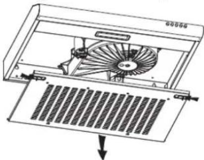
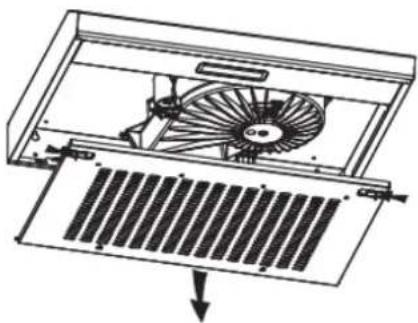
Removing grease mesh filters
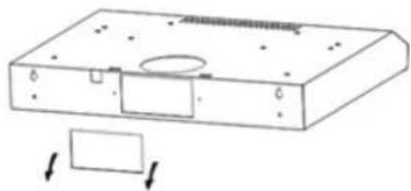
a. Push the grease mesh filter buckles forward and remove the front of the filters.
b. Then push the left or right lower side stops of the filter up until the hanging point at one side stop is not hanging the hood cavity.
c. Finally, take the whole mesh filters away.
Please do not use abrasive detergent for it will damage the hood.
natural_image
Technical line drawing of a fan assembly inside a computer tower, showing internal blades and ventilation slots (no text or symbols)INSTALLING GREASE MESH FILTERS
- To install filters for the following four steps.
- Angle the filter into slots at the back of the hood.
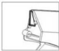
- Push the button on handle of the filter.
- Release the handle once the filter fits into a resting position.
- Repeat to install all filters.
CARBON FILTER – buy separately
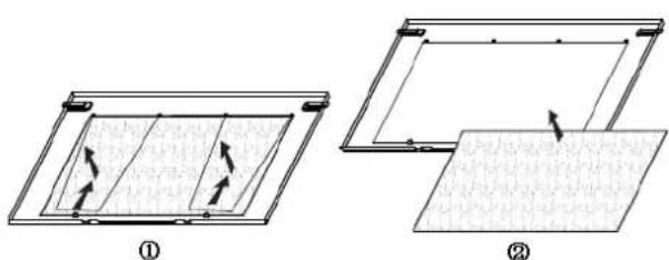
Activated carbon filter can be used to trap odors. Normally the activated carbon filter should be changed at three or six months according to your cooking habit. The installation procedure of activated carbon filter is as below.
- Remove the grease filter.
- Place the carbon filter onto the grease filter.
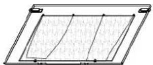
- Fix the properly-adjusted carbon filter with the small steel wire.
- Reinstall the grease filter.
- Use carbon filters for recirculation mode only
NOTE:
Make sure the filter is securely locked. Otherwise, it would lose and cause dangerous. When activated carbon filter attached, the suction power will be lowered.
③
BULB REPLACEMENT

The bulb must be replaced by the manufacturer, its service agent or similarly qualified persons.
Always switch off the electricity supply before carrying out any operations on the appliance. When handling bulb, make sure it is completely cooldown before any direct contact to hands.
When handling globes hold with a cloth or gloves to ensure perspiration does not come in contact with the globe as this can reduce the life of the globe.
Note:
Before changing the lights, make sure that the appliance is plugged off.
Protect against danger when changing lights, such as wearing gloves.
Changing the lights:
- Remove the filter.
- Loosen the 2pcs ST4*8mm self-tapping screw from the lighting panel, take out the lighting fixture.
- Disassembly the 3pcs ST3*12mm screws on the terminal box cover and take down the wire cover.
- Pull out the terminal from the PCB terminal block, disconnect the wire connector and replace the lamp.
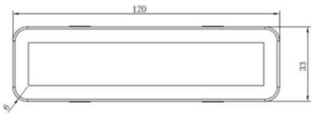
- ILCOS D code for this lamp is: DBS-2/65-H-120/33
- LED modules -rectangle LED lamp
- Max wattage: 1×2 W
– Voltage range: AC 110-240V
- Dimensions:
natural_image
Diagram of an open air fan with a down arrow indicating airflow or cooling (no text or symbols present)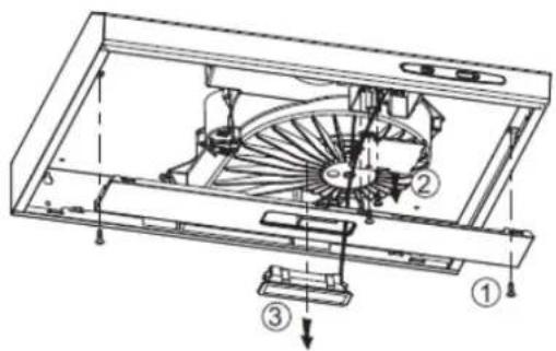
| Suction power: | 209.7 m3/h |
| Motor | 1x85W |
| Color: | White |

Environment friendly disposal
You can help protect the environment!
Please remember to respect the local regulations: hand in the non-working electrical equipment's to an appropriate waste disposal center.

HEINNER is a registered trademark of Network One Distribution SRL. Other brands and product names are trademarks or registered trademarks of their respective holders.
No part of the specifications may be reproduced in any form or by any means or used to make any derivative such as translation, transformation, or adaptation without permission from NETWORK ONE DISTRIBUTION.
Copyright © 2013 Network One Distribution. All rights reserved.
www.heinner.com. http://www.nod.ro
http://www.heinner.com, http://www.nod.ro

This product is in conformity with norms and standards of European Community
Importer: Network One Distribution
Str. Marcel Iancu, nr 3-5, Bucuresti, Romania
Tel: +40 21 211 18 56, www.heinner.com, www.nod.ro
| Product fiche | |
| Trademark | Heinner |
| Model | CH-201WH |
| Annual energy consumption (kWh/year) | 43.7 |
| Energy efficiency class | C |
| Fluid dynamic efficiency | 9.5 |
| Fluid dynamic efficiency class | E |
| Lighting efficiency (lux/W) | 53.0 |
| Lighting efficiency class | A |
| Grease filtering efficiency (%) | 80.8 |
| Grease filtering efficiency class | C |
| Airflow at minimum and maximum speed under normal conditions of use (m3/h) | 99.6/209.7 |
| Airborne acoustical A-weighted sound power emissions at minimum and maximum speed under normal conditions of use (dB(A)) | 55/71 |
| Power consumption in standby mode (W) | - |
| Power consumption in off mode (W) | 0 |
HEINNER
natural_image
Exterior view of a stainless steel air duct cover with ventilation grilles (no text or symbols visible)Pic 2
Pic 3
natural_image
Technical line drawing of a mechanical device with two circular ports and a central hub, set against a grid background (no text or symbols)Pic 4
Метод Б
Pic 5
natural_image
Simple line drawing of a rectangular electronic device with two circular arrows indicating upward motion (no text or symbols)A
natural_image
Technical line drawing of a mechanical housing component with mounting holes and a rectangular base (no text or symbols)B
Pic 6
natural_image
Technical diagrams showing two views (B and D) of a mechanical component with arrows indicating direction (no text or symbols present)Pic 7

VI. ОТСТРАНЯВАНЕ НА ПРОБЛЕМИ
ИНСТАЛИРАНЕ НА ФИЛТРИТЕ ЗА МАЗНИНА
ЗАБЕЛЕЖКИ:
natural_image
Technical diagram of a fan installation inside a rack, showing internal blades and mounting brackets (no text or labels)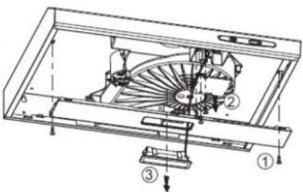
Copyright © 2013 Network One Distribution. All rights reserved.
http://www.heinner.com, http://www.nod.ro
CE
Marcel Iancu Street, 3-5, Bucharest, Romania
Tel: +40 21 211 18 56, www.heinner.com, www.nod.ro
HEINNER
natural_image
Exterior view of a stainless steel air purifier with ventilation grilles (no text or symbols visible)natural_image
Technical line drawing of a mechanical housing or enclosure with mounting holes and internal components (no text or symbols)Pic 3
natural_image
Technical line drawing of a mechanical component with two circular ports and a base plate, set against a grid background (no text or symbols)Pic 4
B. lehetőség
Pic 5
natural_image
Simple line drawing of a rectangular electronic component with mounting holes and a circular feature, no text or symbols present.A
natural_image
Technical line drawing of a mechanical component with mounting holes and a rectangular base (no text or symbols)B
Pic 6
Keringető üzemmód
natural_image
Diagram of a rectangular electronic component with internal components and directional arrows indicating flow or movement (no text or symbols)C
B
natural_image
Isometric view of a rectangular plate with a circular hole and three upward-pointing arrows indicating force or movement (no text or symbols)D
Pic 7

VI. HIBAELHÁRÍTÁS
natural_image
Technical line drawing of a fan assembly with a downward arrow indicating a component (no text or symbols present)A ZSÍRSZÚRÓK BEÜZEMELÉSE
natural_image
Technical diagram of an air vent with fan and ventilation grilles (no text or labels)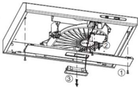
VIII. MÜSZAKI ADATLAP
Copyright © 2013 Network One Distribution. All rights reserved.
http://www.heinner.com, http://www.nod.ro

natural_image
Exterior view of a stainless steel kitchen ventilation cover (no text or symbols visible)- Tradicionalna napa
• Kapacitet apsorpcije: 209,7 m³/h - Boja: nehrđajući čelik
PROTUPOVRATNA ZAKLOPKA
Prije ugradnje, isključite aparat i izvadite ga iz utičnice za napajanje strujom.
UGRADNJA
Metoda A
- Za optimalne učinke, napa mora biti postavljena na udaljenosti od 65-75 cm od površine na kojoj se kuha;
- Da biste izvršili ugradnju u zid, napravite 4 rupe promjera 8 mm na najprikladnijem mjestu, istovremeno uzimajući u obzir udaljenost od središta rupe iza nape;
- Umetnite zidne čepove u napravljene rupe;
- Umetnite vijke u zidne čepove i dobro ih pričvrstite;
- Stavite napu na pričvršćene vijke;
- Zatim koristite priloženi pribor da biste pričvrstili vijke u dvjema rupama unutar nape kako biste pričvrstili napu na zid;
- Postavite ventil "one way" na napu.
Slika 1
Slika 2
Slika 3
natural_image
Technical line drawing of a flatbed electronic device with two circular ports and a central hub, set against a grid background (no text or symbols)Slika 4
Metoda B
Slika 5
Napomena: Raspoloživa su dva načina ventilacije: horizontalna ventilacija i vertikalna ventilacija.
Molimo vas da prije odabira metode ugradnje obratite pozornost na metodu ventilacije.
Vertikalna ventilacije: Prema slici 6A, molimo vas da poklopcem prekrijete stražnji izlaz nape tako se zrak može prozračivati kroz gornji dio.
natural_image
Simple line drawing of a rectangular electronic device with mounting holes and two upward arrows indicating motion (no text or symbols)A
natural_image
Technical line drawing of a rectangular electronic component with mounting holes and a circular cutout (no text or symbols)B
Slika 6
natural_image
Simple line drawing of a rectangular electronic component with internal components and directional arrows (no text or symbols)C
B
natural_image
Isometric view of a rectangular electronic component with mounting holes and internal arrows indicating force or movement (no text or symbols)D
Slika 7

Iz sigurnosnih razloga koristite samo vijke za pričvršćivanje ili ugradnju preporučene u ovom priručniku za uporabu.
VI. POPRAVAK
| PROBLEM | MOGUĆI UZROK | RJEŠENJE |
| Svijetlo se pali, ali motor ne radi. | Prekidač ventilatora je na položaju “isključen”. | Odeberite položaj za funkcioniranje. |
| Prekidač ventilatora je u kvaru. | Obratite se servisnom centru. | |
| Motor je u kvaru. | Obratite se servisnom centru. | |
| Svijetlo se ne pali, a motor ne radi. | Osigurači u stanu su iskočili ili pregorjeli. | Resetirajte ili zamijenite osigurače. |
| Kabel za napajanje je olabavljen ili isključen. | Unesite kabel u utičnicu na odgovarajući način. Uključite izvor napajanja. | |
| Propuštanje ulja. | Ventil za zadržavanje i otvor za usisivanje zraka nisu zabrtvljeni na odgovarajući način. | Odmontirajte nepovratni ventil i koristite material za brtvilo. |
| Porpuštanja na spoju između odjeljka U i kučišta. | Odmontirajte odjeljak na U oblik i zabrtvite. | |
| Svjetla ne rade. | Žarulje su neispravne/ ne rade na odgovarajući način. | Zamijenite žarulje prema uputama. |
| Nedovoljna apsorpcija. | Razmak između nape i ploča aparata za kuhanje je prevelika. | Montirajte napu na odgovrajućoj udaljenosti. |
| Napa se naginje. | Vijak za pričvršćivanje nije dovoljno pričvršćen. | Pričvrstite vijak da biste pričvrstili napu u horizontalnom položaju. |
natural_image
Diagram of a fan blade assembly with a down arrow indicating compression or disassembly (no text or symbols present)UGRADNJA FILTERA ZA MASNOĆU
NAPOMENA:
- Provjerite je li filtar pravilno postavljen.
U suprotnom može oslabiti i prouzrokovati štetu. - Kad se ugradi filter s aktivnim ugljenom, apsorpcijska snaga je manja.
ZAMJENA ŽARULJE

- Metoda B
- Setare ventilare
- INSTALAREA FILTRELOR DE GRĂSIME
- NOTĂ:
- FISA TEHNICA
- Thank you for purchasing this product!
- INTRODUCTION
- CONTENT OF YOUR PACKAGE
- SAFETY PRECAUTIONS
- If this product has arrived damaged please return for change or repair. DO NOT INSTALL THIS APPLANCE IF YOU FOUND IT DANAGED.
- INSTALLATION
- MOUNTING OF THE V-FLAP
- INSTALLATION
- Method A
- Method B
- Notice
- Air ventilation setting
- OPERATION
- TROUBLESHOOTING
- CLEANING AND MAINTENANCE
- CAUTION
- GENERAL
- STAINLESS STEEL
- CONTROL PANEL SURFACE
- GREASE MESH FILTERS
- Removing grease mesh filters
- Please do not use abrasive detergent for it will damage the hood.
- INSTALLING GREASE MESH FILTERS
- CARBON FILTER – buy separately
- NOTE:
- BULB REPLACEMENT
- Environment friendly disposal
- HEINNER
- Метод Б
- ОТСТРАНЯВАНЕ НА ПРОБЛЕМИ
- ИНСТАЛИРАНЕ НА ФИЛТРИТЕ ЗА МАЗНИНА
- ЗАБЕЛЕЖКИ:
- CE
- lehetőség
- Keringető üzemmód
- A ZSÍRSZÚRÓK BEÜZEMELÉSE
- MÜSZAKI ADATLAP
- PROTUPOVRATNA ZAKLOPKA
- UGRADNJA
- Metoda A
- POPRAVAK
- UGRADNJA FILTERA ZA MASNOĆU
- NAPOMENA:
- ZAMJENA ŽARULJE
Brand : Heinner
Model : CH-201SS
Category : Range hood