
Satmeter HD 4 Combo V2 - Measurement MEGASAT - Free user manual and instructions
Find the device manual for free Satmeter HD 4 Combo V2 MEGASAT in PDF.


| Product Type | Satellite and terrestrial signal meter / analyzer |
| Brand | Megasat |
| Model | Satmeter HD 4 Combo V2 |
| Dimensions (W x H x D) | 80 x 177 x 34 mm |
| Weight | 240 g |
| Display | 2.7 inch TFT LCD, 400 x 360 pixels |
| Battery | Li-Ion 7.4 V / 1400 mAh, up to 3 hours operation |
| Power Supply | AC 100-240 V / DC 12 V, 1 A (adapter included) |
| Satellite Frequency Range | 950 MHz - 2150 MHz |
| Terrestrial/Cable Frequency Range | 42 MHz - 1005 MHz |
| Demodulation | DVB-S/S2 (QPSK, 8PSK), DVB-T/T2 (QPSK, QAM), DVB-C/C2 (QAM), Analog TV |
| Measurement Parameters | PWR (dBµV), CNR, CBER, VBER, LBER, MER, SNR, Link Margin, Frequency Offset, STR, QTY |
| LNB Output | 13 V (Vertical) / 18 V (Horizontal), max 400 mA, short-circuit protection |
| DiSEqC Support | 1.0, 1.1, 1.2, USALS, Auto DiSEqC detection |
| Unicable Compatibility | EN 50494 (Unicable I) and EN 50607 (Unicable II) |
| Spectrum Analysis | Real-time, adjustable frequency range and resolution |
| Compass and Alignment | Integrated motion sensor, graphical satellite pointer, azimuth/elevation/skew calculation |
| Firmware Update | Via mini-USB port (USB to mini-USB adapter optional) |
| Input Impedance | 75 Ω |
| Input Level Range | Satellite: 35-100 dBµV; Terrestrial/Cable: 30-100 dBµV |
| Antenna Power Output | Off, 5 V, 12 V, 18 V, 24 V (for active DVB-T antennas) |
| Safety Features | LNB short-circuit protection and indication, overvoltage protection |
| Included Accessories | 230 V charging adapter, 12 V car adapter, protective cover with carrying strap, user manual |
| Languages | Multilingual menu (e.g., English, German, etc.) |
| Repairability | No spare parts listed; firmware updatable via mini-USB |
Frequently Asked Questions - Satmeter HD 4 Combo V2 MEGASAT
User questions about Satmeter HD 4 Combo V2 MEGASAT
0 question about this device. Answer the ones you know or ask your own.
Ask a new question about this device
Download the instructions for your Measurement in PDF format for free! Find your manual Satmeter HD 4 Combo V2 - MEGASAT and take your electronic device back in hand. On this page are published all the documents necessary for the use of your device. Satmeter HD 4 Combo V2 by MEGASAT.
USER MANUAL Satmeter HD 4 Combo V2 MEGASAT
(18 V = Horizontal / 13 V = Vertical)
Bedienung
natural_image
Illustration of a satellite and a handheld device with a green arrow indicating direction (no text or symbols)4. Hauptmenü
■ Video/Audio-System: NTSC_M, PAL_G, PAL_M, PAL_N, PAL_K, PAL_L, PAL_I, SECAM_L, SECAM_B, SECAM_D
Anschlüsse
1.1 Safety instructions....03
1.2 General features 03
1.3 Scope of delivery 03
2. Designations and key assignment....04
3. Quick measurement guide 06
4. Main menu
4.1 Satellite TV....07
4.1.1 Measured....08
4.1.2 Satellite edit.... 12
4.1.3 Multi TP (Transponder).... 13
4.1.4 Spectrum analyse.... 14
4.1.5 Angle calculation.... 15
4.1.6 Satellite identification 18
4.2 Terrestrial television.... 19
4.2.1 Measured 20
4.2.2 Auto Scan 21
4.2.3 Channel list.... 21
4.2.4 Spectrum 22
4.2.5 Multi-channel.... 23
4.2.6 Antenna Power 23
4.5 System setting....30
5. Technical data .... 31
1.1 Safety Instructions
- Never spill liquids of any kind on the appliance. Liquids increase the risk of electric shock and damage to the product.
- The appliance is not shockproof. Do not use the unit as a hammer and take care that it cannot fall from a great height.
- Do not immerse the appliance in water. Avoid moisture and store the product in a dry place.
- Switch the unit off when not in use.
- Observe the specified power supply. Only use the mains adapter supplied to charge the unit.
1.2 General features
- Extremely fast and accurate measurement with high sensitivity of DVB-S / -S2 / -T / -T2 / -C / -C2 and analogue TV signals.
- Programmed satellite and transponder list
• 2.7 inch TFT LCD display with 400 x 360 pixels - Unicable compatible (EN 50494 + EN 50607)
- Spectrum analysis
• Auto DiSEqC detection for DiSEqC 1.0 - Satellite and transponder identification
• Calculation of rotation and tilt angle of the antenna
• Control of the different planes (HH / HL / VH / VL).
• Measurement of switching voltage and 22 KHz commands. - DiSEqC measurement and control of switching commands.
- Integrated compass function. If the measuring device is turned or tilted, the current angle is automatically shown on the display. Alternatively, the selected satellite can be displayed graphically to quickly determine the correct position.
• Display of dBμV, CNR, PWR, CBER, VBER, LBER, MER, SNR, signal strength/quality cent - Integrated power battery with up to 3 hours operating time
- Firmware updates via mini-USB (USB to mini-USB adapter optionally available)
1.3 Delivery
- Megasat HD 4 Combo V2
• 230 Volt charging adapter
• 12 Volt car charging adapter - Protective cover incl. carrying strap
- User manual
2. Designations and key assignment
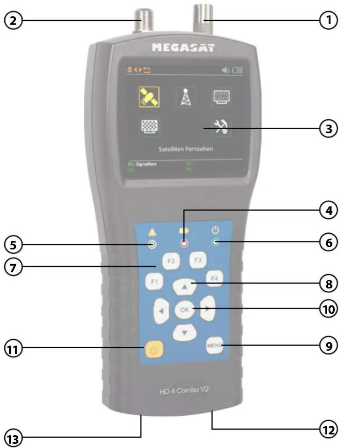
2. Designations and key assignment
- ANT In Antenna signal input (DVB-T or DVB-C)
- LNB In Satellite signal input (DVB-S)
- LCD Display Shows the menu
- Red: the battery is charging / Green: the battery is charged.
- Flashes briefly when the antenna is short-circuit.
-
Power indicator: Device is switched on or off.
-
Funktionstasten F1: Main Menu Signal tone on/off (Function key in various menus)
F2: Function key in various menus (Function you can see in menu OSD)
F3: Function key in various menus (Function you can see in menu OSD)
F4: Function key in various menus (Function you can see in menu OSD)
Note: The functions of the F keys depend on it, which submenu you are in.
8. Navigation
▲▼ Navigation through the menu / changing values
◀▶ Navigation through the menu / changing values
-
Menu Press Menu to enter or exit the menu.
-
OK In the menus, press OK to confirm your selection.
-
Power Switch the machine on or off. Press and hold the key for 2 seconds to switch the machine on.
-
DC Connection for power or firmware update.
-
Reset Resetting the unit to the factory settings.
3. Quick measurement guide
- Connect the antenna to the LNB input of the meter.
- Turn on the power of the measuring device. The main menu appears. Use the ▲▼ ◀▶ buttons to navigate between the individual menu items and confirm the item „Measure“ with OK.
- Select the menu item „Satellite TV“.
- Select the menu item "Measure" to perform a satellite search or to display the current measured values.
- Use the ◀▶ keys to change the satellite or press OK to display the satellite list.
- As soon as the coaxial line has been connected correctly and the settings for the satellite search have been entered correctly, the corresponding values of the measurement are shown on the display.
- Please read the instructions carefully to familiarise yourself with all the functions.
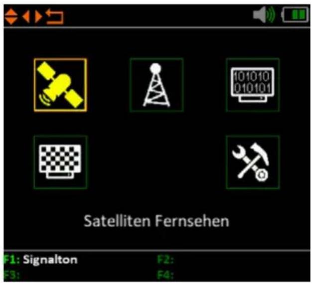
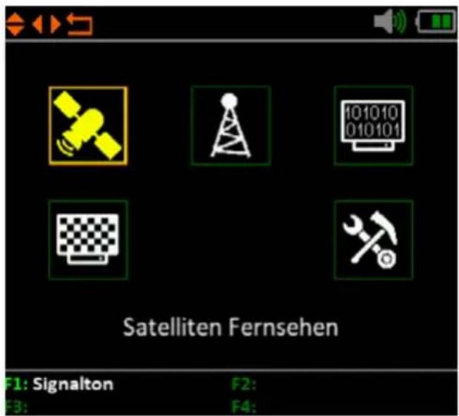
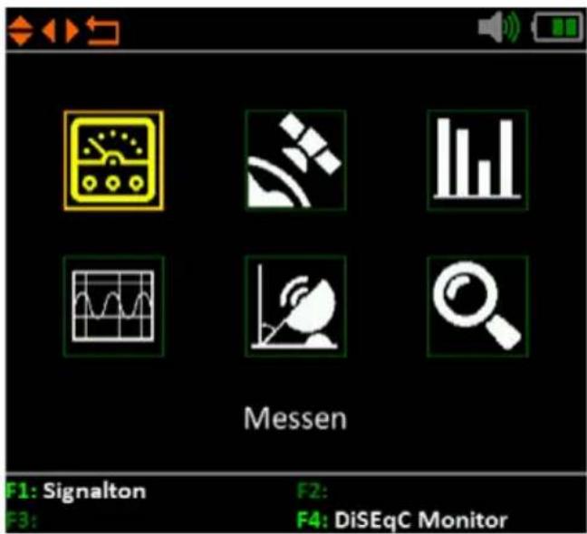
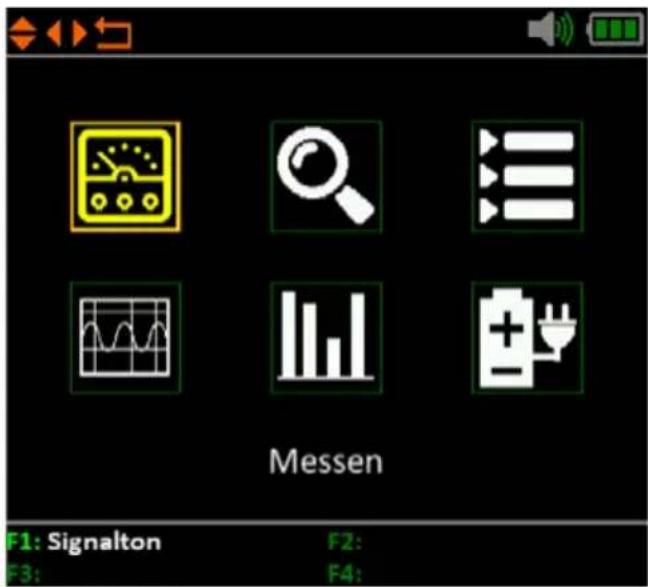
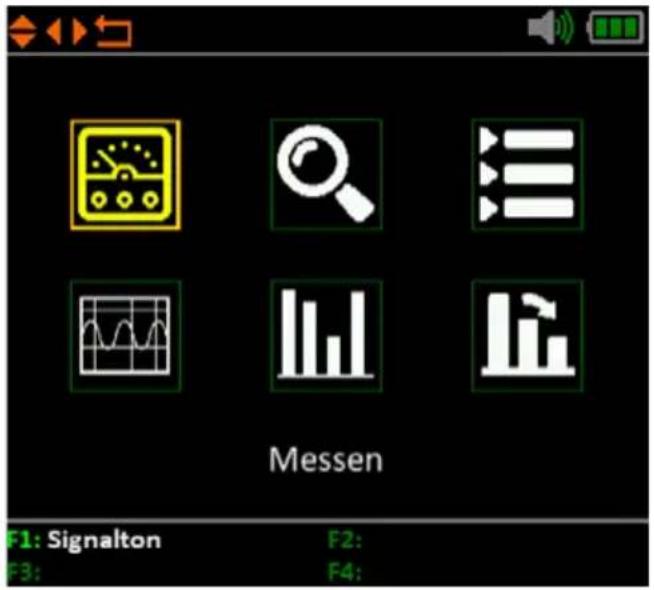
When you switch on the meter, the main menu opens automatically.
Use the ◀▶ buttons or the ▲▼ buttons to navigate the menu. Press OK to enter the relevant sub-menu. Press MENU to return to the main menu.
There are 6 menu items in total:
- Satellite Television
• Terrestrial Television - Cable television
- Analogue television
- System setting
- Measure
- Edit Satellite
- Multi TP (Transponder)
- Spectrum
- Angle calculation
- Satellite identification
4.1.1 Measurement
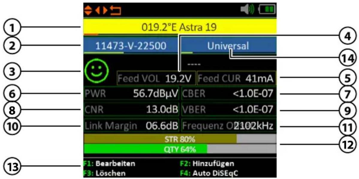
1. Satellit
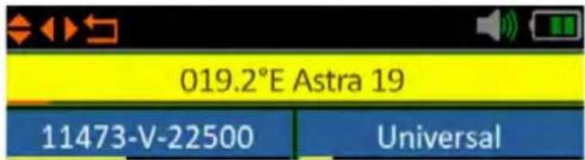
Shows the current satellite. Use the ◀▶ buttons to change the satellite. Press OK to move to the satellite list. Use the ct the desired one and press OK to confirm.
2. Transponder
Shows the current transponder. Use the ◀▶ buttons to under. Press OK to enter a transponder ▲▼ buttons to change the value).
- Smiley symbol Indicates whether the set satellite has been found.
- LNB voltage Shows the current LNB voltage (18 V = horizontal / 13 V = vertical)
- LNB power Shows the current LNB power consumption
- PWR Indicates the current level of the signal in dBμV.
- CBER Indicates the current CBER value of the signal.
- CNR Indicates the current CNR value of the signal.
- VBER Indicates the current VBER value of the signal.
- Link Margin Shows the difference between the minimum expected power and the sensitivity of the receiver.
- Frequency offset Displays the current frequency offset.
- STR / QTY Indicates the current signal strength (STR) and the current signal quality (QTY) of the signal.
- F-keys Various function keys for further actions.
- LNB settings To change the respective LNB or Unicable settings.
4. Main menu
Satelliten edit
Use the ◀▶ buttons to select the satellite you want to edit.
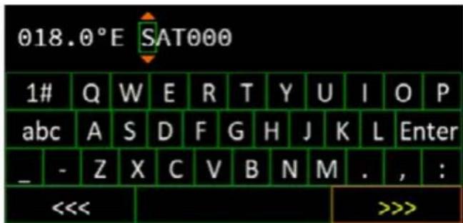
- You can edit the name of the satellite with the F1 key. A keypad is displayed which you can use to change the name and the degree.
-
Press the F2 key to add a satellite. A keypad is displayed where you can enter the name and the degree.
-
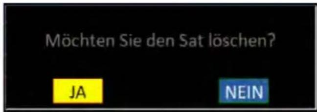
With the F3 key you can select a Delete satellites.
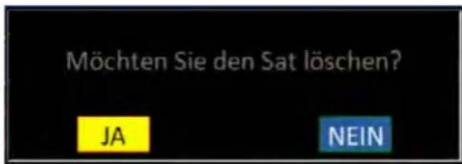
- Press the F4 key to access the Auto DiSEqC function.
4. Main menu
Edit Transponder
Use the ◀▶ keys to select the transponder you want to edit.
-
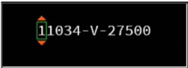
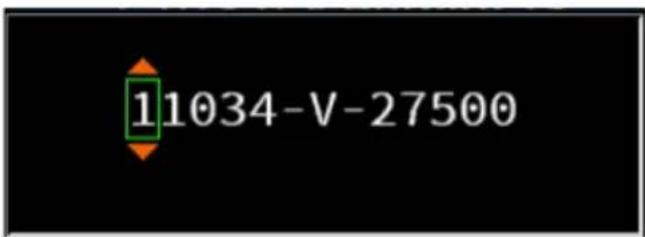
You can change the value of the transponder with the F1 key. Use the up/down button to change the corresponding digits.
-
Press the F2 key to add a new transponder. Use the up/down button to change the digits and confirm with OK.
-
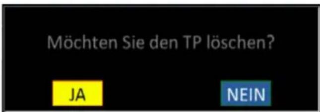
Press the F3 key to delete the selected transponder.
-
Press the F4 key to display the signal quality and strength in full on the screen.
Note:
Transponder data can change at any time. Please check them for correctness in case of reception problems.

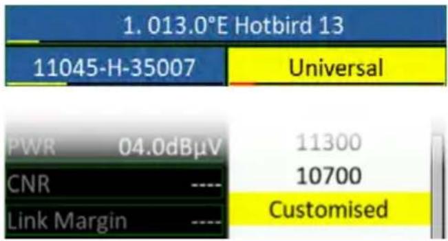
Use the ◀▶ keys to select the LNB settings and confirm with OK.
Confirm the „Customized“ item to access other settings such as DiSEqC or Unicable.
Confirm the item „Customized“ to access further settings such as DiSEqC or Unicable.
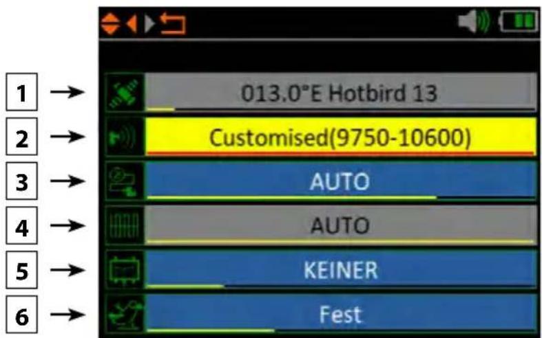
- Shows the currently selected satellite.
- Change the LNB frequency if necessary (default: 9750-10600).
- If necessary, change the LNB power supply. Select from AUTO, 18 V, 13 V, or OFF.
- 22 KHz switching (only adjustable with manual LNB setting).
- Select from NONE, DiSEqC 1.0, DiSEqC 1.1, SCD (Unicable) or SCD2 (Unicable II). After you have confirmed with OK, you can use the F1 key to make the respective settings (e.g. the port selection for DiSEqC or the respective frequency for Unicable.
- Select here how the satellite system is operated (fixed, USALS or DiSEqC 1.2). In case of a motor control please refer to your motor manual for further settings.
4. Main menu
4.1.2 Edit satellite
In this menu you can edit the satellite and transponder list. Use the ◀▶ buttons to switch between the satellite list and transponder list.
- Press the F1 key to access the LNB settings. There you can make settings for the respective satellite.
Note: Press the OK button to re-name a satellite or transponder.
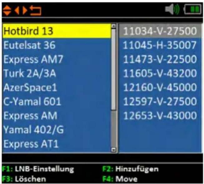
- You can add a satellite with the F2 key. A keypad appears where you can enter the name and the number of degrees.
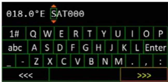
- With the F3 key you can delete a delete a satellite.
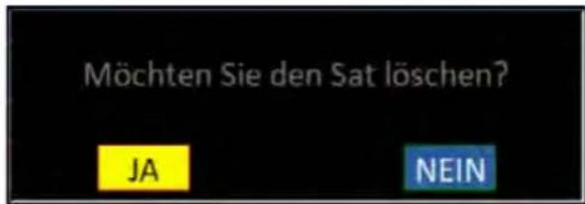
- Use the F4 key to sort the satellites. Use the ▲▼ keys to select a satellite or transponder. Press the F4 key to highlight it. Use the ▲▼ keys to move the selection to the desired position and confirm again with F4.
4. Main menu
4.1.3 Multi TP (Transponder)
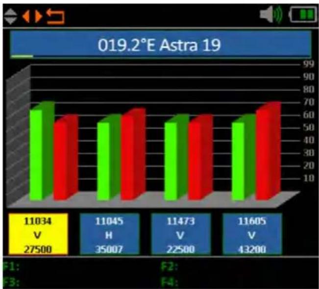
If you want to calibrate a satellite system with a Quattro LNB, this control helps you to have a complete overview of all LNB levels.
Here you can see all levels of the LNB (HL / VL / HH / VH). Thus, every connection can be checked immediately for signal strength and quality.
You can also measure the appropriate level by connecting individual lines to determine the correct assignment of the connections on the multiswitch.
bar
019.2°E Astra 19 | Category | Green Bar Value | Red Bar Value | | :--- | :--- | :--- | | 1 | 68 | 58 | | 2 | 60 | 62 | | 3 | 52 | 65 | | 4 | 52 | 60 | | 5 | 52 | 60 | | 6 | 52 | 60 | | 7 | 52 | 68 | | 8 | 52 | 70 |Note:
You can change the default transponders. However, they are reset to the preset values after you exit the menu.
4.1.4 Spectrum analysis
line
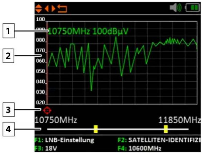
| Frequency | Value | | --------- | --------- | | 10750MHz | 100dBμV | | 11850MHz | 10600MHz |- Shows the current frequency and the signal strength in dBμV.
- Shows the range of the power level (0\~100 dBμV).
- Use the◀▶ buttons to search for the desired frequency and display the corresponding value.
- Use the ▲▼ buttons to navigate to the horizontal line. If selected, the first yellow bar will be marked RED. Now set the start frequency of the spectrum with the ◀▶ buttons. Repeat the procedure with the other yellow bar to set the final frequency.
- Press the F1 key to access the LNB settings.
- The F2 key takes you to the satellite identification.
- Press the F3 key to switch between 13V and 18V.
- The F4 key toggles between 9750 MHz (22K) and 10600 MHz.
4. Main menu
4.1.5 Angle calculation
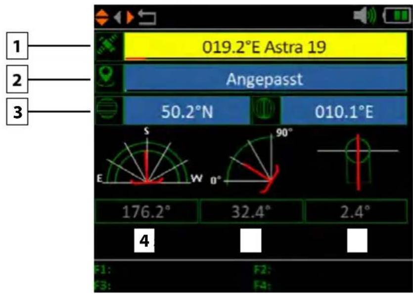
- Use the ◀▶ buttons to select the desired satellite.
- Press OK to select the location. Use the navigation keys to change the value. The longitude and latitude are automatically calculated.
- If you have selected "Customised", you will have to determine your location yourself. Enter the longitude and latitude manually.
- Shows the horizontal angle of the antenna (azimuth).
- Shows the vertical angle of the antenna (elevation).
- Shows the skew angle (rotation) of the LNB.
4. Main menu
Compass
Note:
Before use, you must calibrate the meter. To do this, swing it back and forth in the shape of a figure eight (8).
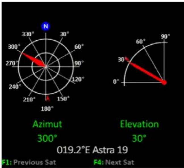
Example: You are in Berlin and want to adjust the satellite „Astra 19.2° East“. The values how you have to adjust the mirror are:
- 29.2^ angle of inclination (vertical)
• 19.2° east of south (horizontal)
radar
019.2°E Astra 19 | Direction | Azimuth (°) | | :--- | :--- | | Azimuth | 300 | | Elevation | 30 |Stand with the meter facing south. Now turn it in an easterly direction (to the left) until the pointer is aligned with the red mark.
Now tilt the meter until the tilt angle pointer aligns with the red mark.
4. Main menu
Alignment
Note:
Before use, you must calibrate the meter. To do this, swing it back and forth in the shape of a figure eight (8).
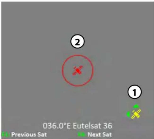
- Shows the position of the selected satellite.
- Shows you the direction of the meter.
Operation
The meter is equipped with a motion sensor. As soon as you turn or tilt the meter, the values are displayed in real time.
- Place or hold the meter horizontally.
- Orientate yourself by the green arrows (yellow satellite symbol), this shows you the current direction of the satellite.
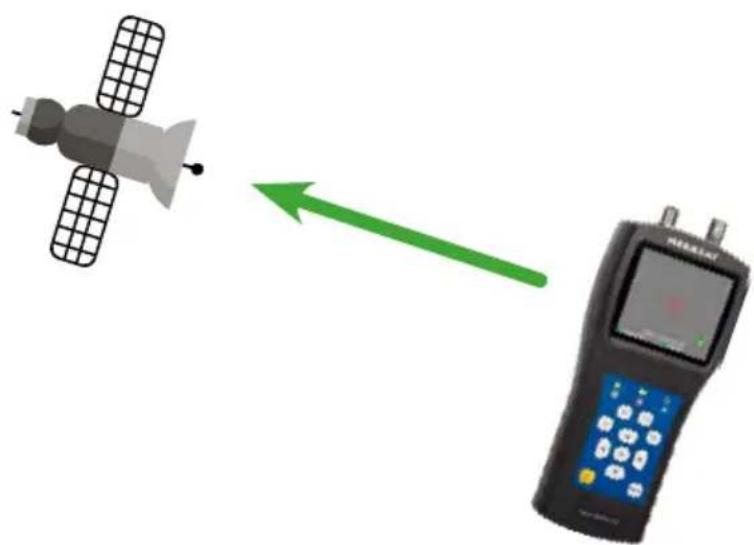
- Turn the meter in the direction of the satellite (1) until both satellite symbols are on top of each other and the green arrows are extinguished. Now you have the direction in which the mirror must point.
natural_image
Illustration of a satellite and a handheld device with a green arrow indicating direction (no text or symbols)4. Main menu
4.1.6 Satellite identification
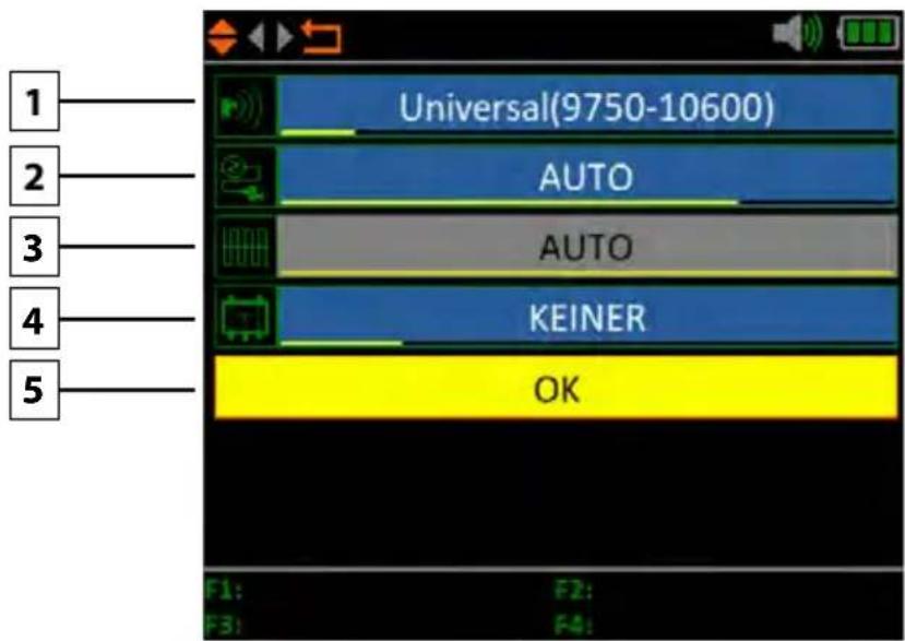
- If necessary, change the LNB frequency (default: 9750-10600).
- If necessary, change the LNB power supply. Select between AUTO, 18 V, 13 V, or OFF.
- 22 KHz switching (only adjustable with manual LNB setting).
- Select from NONE, DiSEqC 1.0, DiSEqC 1.1, SCD (Unicable) or SCD2 (Unicable II). After you have confirmed with OK, you can use the F1 key to make the respective settings (e.g. the port selection for DiSEqC or the respective frequency for Unicable.
- Select here how the satellite system is operated (fixed, USALS or DiSEqC 1.2). In case of a motor control please refer to your motor manual for further settings.
- Then press OK to perform satellite identification.
Note:
Satellite data (transponders) can change at any time. Please check them for correctness in case of reception problems.
4. Main menu
4.2 Terrestrial television
The menu item „Terrestrial TV“ consists of 6 submenus:
- Measure
- Auto Scan
- Channel list
- Spectrum
- Multichannel
- Antenna Power
4.2.1 Measurement
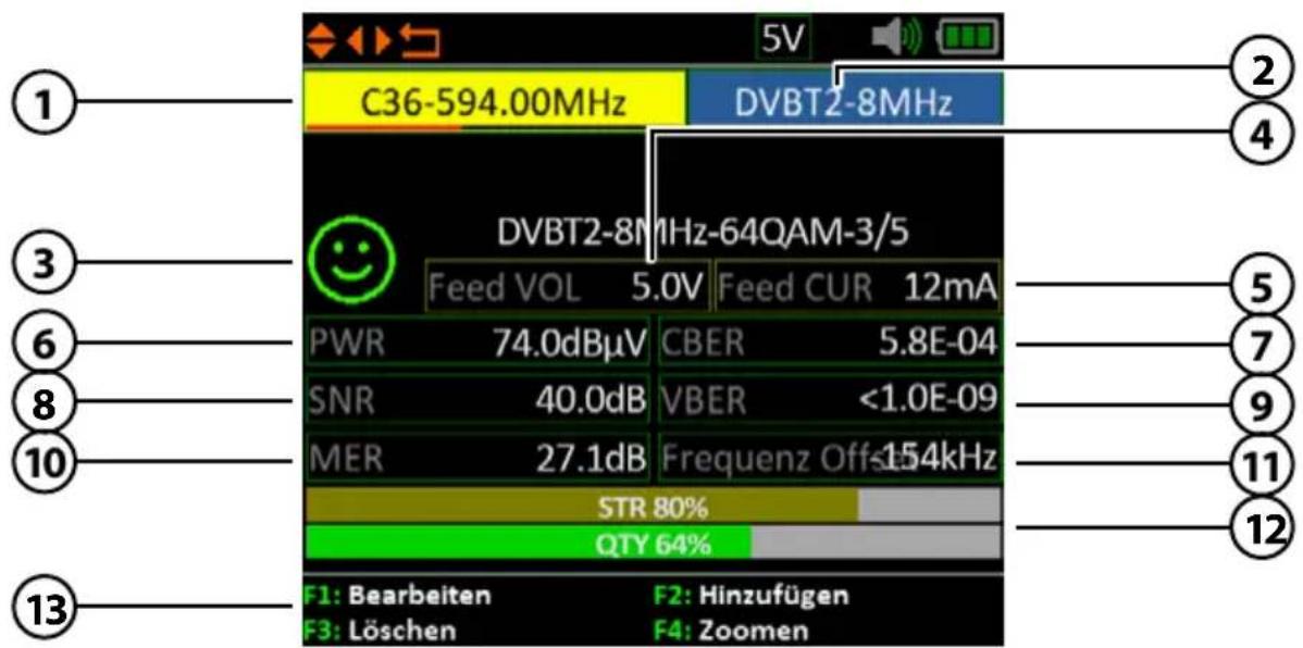
1. Kanal
Shows the current channel. Use the ◀▶ buttons to change
nel. Press OK to move to the channel list. Use the
▲▼ buttons to select the desired one and press OK to confirm.
- Bandbreite Displays the current bandwidth of the channel.
- Smiley-Symbol Indicates whether the set satellite has been found.
- Output power Shows the current output voltage for active DVB-T antennas
- Power consumption Shows the current consumption
- PWR Indicates the current level of the signal in dBμV.
- CBER Indicates the current CBER value of the signal.
- SNR Indicates the current SNR value of the signal.
- VBER Indicates the current VBER value of the signal.
- MER Indicates the current MER value of the signal.
- Frequency offset Displays the current frequency offset.
- STR / QTY Indicates the current signal strength (STR) and the current signal quality (QTY) of the signal.
- F-keys Various function keys for further actions.
4. Main menu
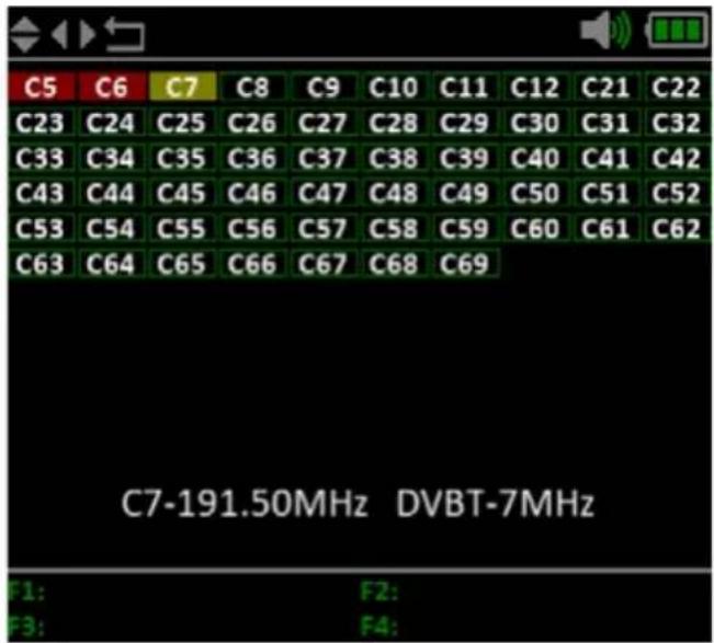
4.2.2 Auto Scan
Performs an automatic search of the various frequencies.
On the frequencies marked in green, you are currently receiving a DVB-T signal.
On frequencies marked in red, there is no signal at the current location or the signal is too weak.
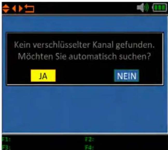
After completing the search process, you can display the list of received frequencies and transfer them to the frequency list.
In this list, found frequencies of the auto search are displayed.
- Shows the current frequency and signal strength in dBμV.
- Shows the range of the power level (0\~100 dBμV).
- Switch with the ◀▶ buttons to search for the desired frequency and display the corresponding value.
- Navigate with the ▲▼ keys to the horizontal line. If selected, the first yellow bar will be marked RED. Now use the ◀▶ keys to set the start frequency of the spectrum. Repeat the procedure with the other yellow bar to set the final frequency.
4. Main menu
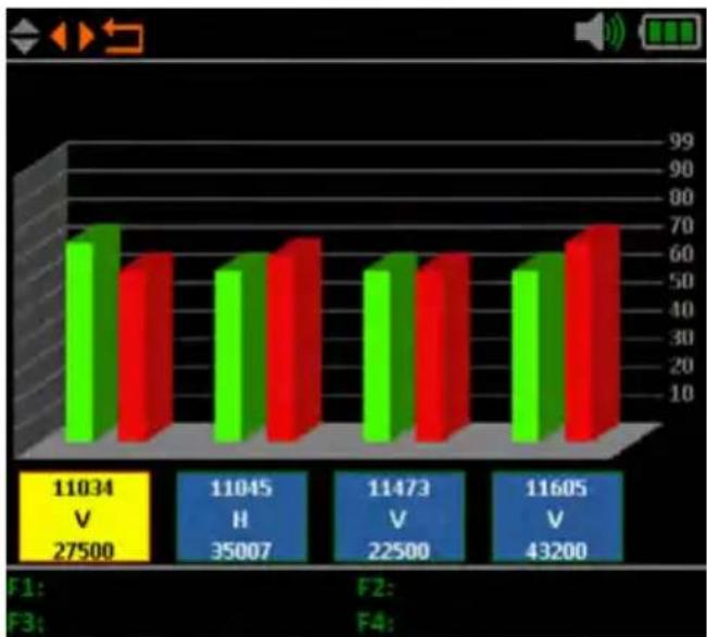
4.2.5 Multi channel
This display shows the level (dμBV) of 6 channels simultaneously. Use the ◀▶ buttons to select a channel, press OK to add another channel to the list.
Note:
You can change the preset channels. However, these are reset to the pre-set values after leaving the menu.
bar
| Category | Value | |---|---| | F1: V 27500 | 11034 | | F2: H 35007 | 11045 | | F3: V 22500 | 11473 | | F4: V 43200 | 11605 |4.2.6 Antenna Power
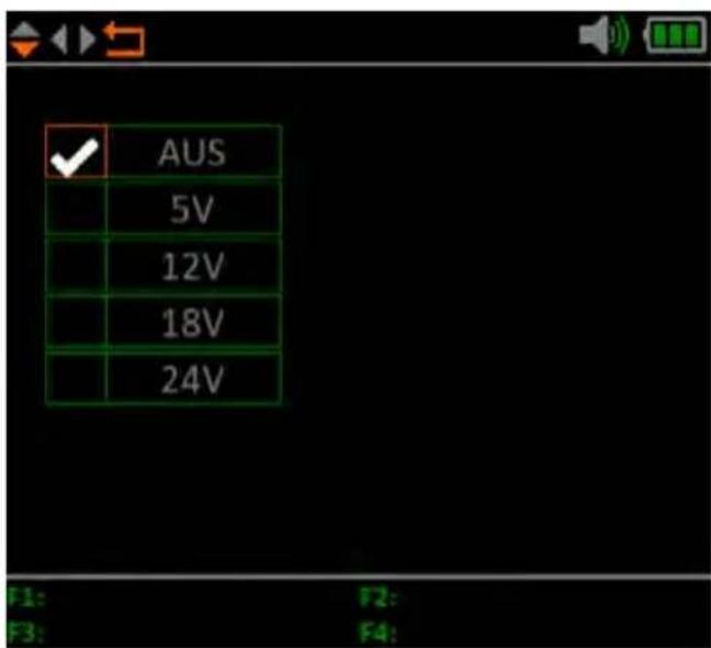
In this menu item you can set the power supply of the antenna.
Depending on the type of DVB-T antenna you are using, you must set the power supply here.
If you are using an active DVB-T antenna with its own power supply, select „0 V“. If you are using an antenna without its own power supply, select 5 V, 12 V, 18 V or 24 V depending on the antenna so that it is supplied with power.
4. Main menu
4.3 Cable Television
The menu item „Cable TV“ consists of 6 submenus:
- Measure
- Auto Scan
- Channel list
- Spectrum
- Multichannel
- Tilt
4. Main menu
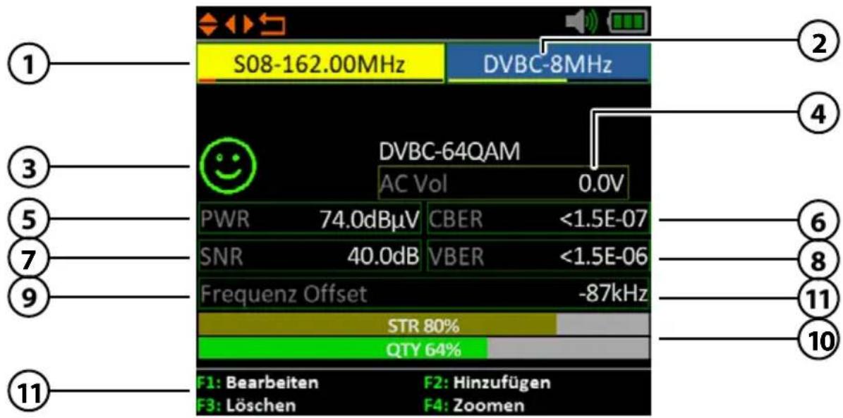
4.3.1 Measurement
1. Kanal
Shows the current channel. Use the ◀▶ buttons to change
nel. Press OK to move to the channel list. Use the
▲▼ buttons to select the desired one and press OK to confirm.
- Bandbreite Displays the current bandwidth of the channel.
- Smiley-Symbol Indicates whether the set satellite has been found.
- AC / DC Vol Shows the current voltage of the power supply.
Switching between AC and DC is done with the F4 key.
- PWR Indicates the current level of the signal in dBμV.
- CBER Indicates the current CBER value of the signal.
- SNR Indicates the current SNR value of the signal.
- VBER Indicates the current VBER value of the signal.
- Frequency offset Displays the current frequency offset.
- STR/QTY Indicates the current signal strength (STR) and the current signal quality (QTY) of the signal.
- F-keys Various function keys for further actions.
4. Main menu
4.3.2 Auto Scan
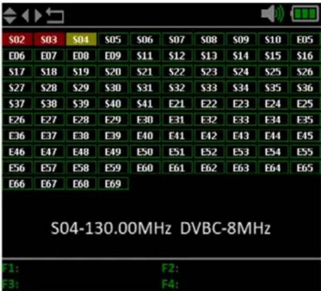
Performs an automatic search of the various frequencies.
On the frequencies marked in green, you are currently receiving a DVB-C signal.
On frequencies marked in red, there is no signal or the signal is too weak.
After completing the search process, you can display the list of received frequencies and transfer them to the frequency list.
4.3.3 Channel list
In this list, found frequencies of the auto search are displayed.
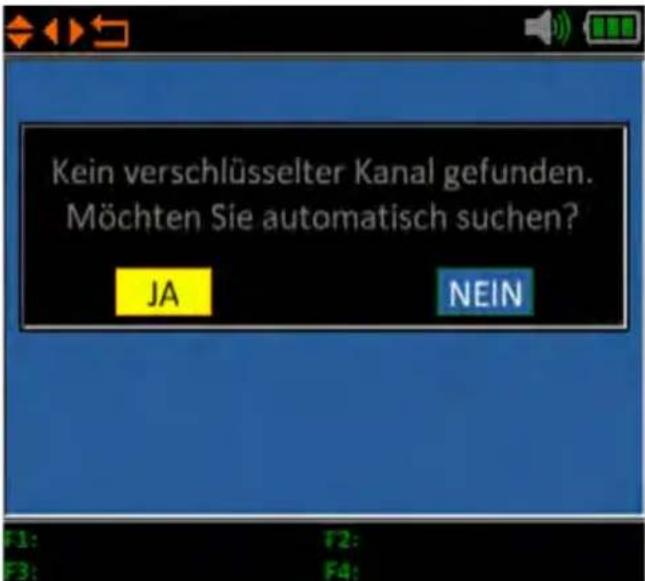
- Shows the current frequency and signal strength in dBμV.
- Shows the range of the power level (0\~100 dBμV).
- Switch with the ◀▶ buttons to search for the desired frequency and display the corresponding value.
- Navigate with the ▲▼ keys to the horizontal line. If selected, the first yellow bar will be marked RED. Now use the ◀▶ keys to set the start frequency of the spectrum. Repeat the procedure with the other yellow bar to set the final frequency.
4. Main menu
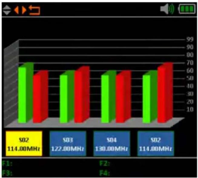
4.3.5 Multi channel
This display shows the level (dμBV) of 6 channels simultaneously. Use the ◀▶ buttons to select a channel, press OK to add another channel to the list.
Note:
You can change the preset channels. However, these are reset to the pre-set values after leaving the menu.
bar
| Category | Value | |---|---| | S02 | 114.00MHz | | S03 | 122.00MHz | | S04 | 130.00MHz | | S02 | 114.00MHz |4.3.6 Tilt
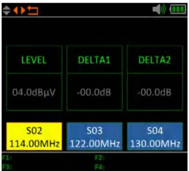
This display shows the level (dμBV) of 3 channels simultaneously. Use the ◀▶ buttons to select a channel, press OK to add another channel to the list.
Note:
You can change the preset channels. However, these are reset to the preset values after leaving the menu.
4. Main menu
4.4 Analog Television
The procedure for measuring analogue TV is the same as for cable TV.
The menu item „Analogue TV“ consists of 3 submenus:
- Measure
- Spectrum
- Tilt
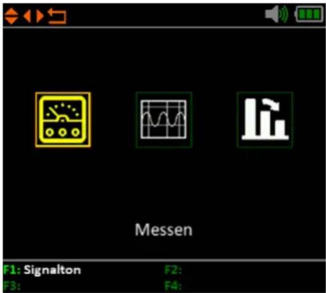
4. Main menu
4.5 System settings
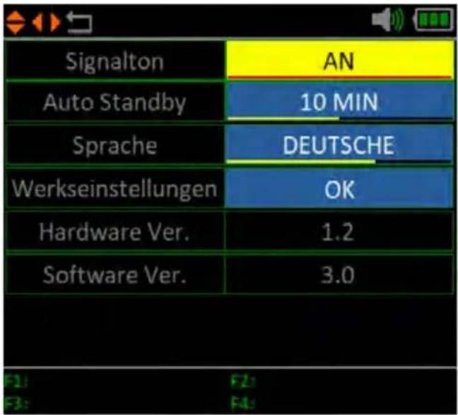
Signal tone Enable or disable the key tones.
Auto standby Set the auto standby time.
Choose between OFF, 10 min, 20 min or 30 min.
Language Set the language of the menu.
Factory setting To return the device to its factory settings, confirm with OK.
ATTENTION: All data you have entered will be deleted!
Hardware ver. Shows the current hardware version of the machine.
Software ver. Shows the current firmware version of the machine.
5. Specifications
General
■ Measurement of DVB-S / -S2 / -T / -T2 / -C / -C2 / Analogue TV
■ 2.7 inch (6.9 cm) LCD colour display (400 x 360 pixels)
■ Optical and acoustic signal display
■ Rechargeable battery: Li-Ion (7.4 V / 1400 mA/h) up to 3 hours of operation
■ Quick charge of the battery in approx. 3 hours
■ Long standby time and low power consumption
■ Easy editing of basic settings
■ Mini-USB connection for firmware updates
■ Power supply: AC 100-240 V / DC 12 V, 1 A
DVB-S / S2
■ LNB short-circuit protection and short-circuit indication
■ Real-time spectrum analysis
■ Satellite and transponder identification
■ All DiSEqC protocol monitors are based on 22 KHz signal
■ Angle calculation of azimuth and elevation
■ Graphical satellite alignment display
■ Displays: PWR, CNR, CBER, VBER, Link Margin
■ Feed CUR, Feed VOL, Frequency offset
■ DiSEqC 1.0 / 1.1 / 1.2 / USALS
■ Auto DiSEqC detection for DiSEqC 1.0
■ Unicable I & II (EN 50494 / EN 50607)
■ DiSEqC measurement and control of switching commands
■ Measurement of switching voltage and 22 KHz commands
■ Coaxial cable detection for Quattro LNB
■ Frequency range: 950 MHz \~ 2150 MHz
■ Demodulation DVB-S: QPSK
■ Demodulation DVB-S2: QPSK, 8QPSK
■ Code Rate DVB-S: 1/2, 2/3, 3/4, 5/6, 7/8, Auto
■ Code Rate DVB-S2: 2/5, 1/2, 3/5, 2/3, 3/4, 5/6, 8/9, 9/10, Auto
■ Symbol rate: 1M sym/s to 45 Msym/s
■ Input impedance: 75 Ω
■ Input level: 35 \~ 100 dBμV
■ LNB polarisation, voltage: Vertical 13 V, Horizontal 18 V, 400 mA
■ Bandwidth: C/Ku band selectable
Note:
Weight and dimensions are not the absolute exact values. Technical details may be changed at any time and without prior notice.
DVB-T / T2
■ Displays: PWR, VBER, CBER, LBER, SNR, MER, Freq. Offset
■ Real-time spectrum analysis
- Scope display
■ Automatic channel search
■ Frequency range DVB-T/-T2: 42 MHz \~ 1005 MHz
■ FFT type DVB-T: 2k, 8k
■ FFT type DVB-T 2: 1k, 2k, 4k, 8k, 16k, 32k + extended bandwidth
■ Guard interval DVB-T/-T2: auto
■ Code rate DVB-T: 1/2, 2/3, 3/4, 5/6, 7/8
■ Code rate DVB-T2: 1/2, 3/5, 2/3, 3/4, 4/5, 5/6, 1/3, 2/5
■ Modulation DVB-T: QPSK,16-QAM, 64-QAM
■ Modulation DVB-T2: 16, 32, 64, 128, 256 QAM
■ Bandwidth DVB-T: 6, 7 and 8 MHz
■ Bandwidth DVB-T2: 1.7, 5, 6, 7 and 8 MHz
■ Input level: 30 \~ 100 dBμV
■ Power supply: Off, 5 V, 12 V, 18 V, 24 V
DVB-C / C2
■ Display: PWR, CBER, VBER, SNR, Freq. Offset
■ Real-time spectrum analysis
- Tilt display
■ Automatic channel search
■ Frequency range: 42 MHz \~ 1005 MHz
■ Symbol rate DVB-C: 1.7 \~ 7.2 Msym/s
■ FFT type: 4k
■ Code rate DVB-C: 16QAM, 32QAM, 64QAM, 128QAM, 256QAM
■ Code rate DVB-C2: 16QAM, 64QAM, 256QAM, 1024QAM, 4096QAM
■ Guard interval DVB-C2: 6, 8 MHz
■ Input level: 35 \~ 100 dBμV
Analog-TV
■ Frequency range: 42 MHz \~ 1005 MHz
■ Video/Audio-System: NTSC_M, PAL_G, PAL_M, PAL_N, PAL_K, PAL_L, PAL_I, SECAM_L, SECAM_B, SECAM_D
Connections
■ 1x Mini USB
■ 1x F connection (for DVB-S/S2)
■ 1x RF connection (for DVB-T/T2 and DVB-C)
■ 1x power supply
Logistical data
■ Dimensions:
80 × 177 × 34 mm (W/H/D)
■ Weight: 240 g
Conformity information
Megasat Werke GmbH hereby declares that the following equipment is in conformity with the essential requirements and other relevant provisions of Directive 2014/30/EU and 2014/35/EU and the Radio Equipment Directive 2014/53/EU
The declaration of conformity for these products is available: Megasat Werke GmbH, Brückenstraße 2a, D-97618 Niederlauer
You can download the declaration of conformity from our homepage: www.megasat.tv/support/downloads
PRODUCT REGISTRATION
Registering your Megasat product gives you access to our automatic e-mail notifications. If your product requires new firmware, you will be notified by e-mail.
For registration please visit our homepage www.megasat.tv
You can find the form in Support → Product registration
Version: 2.0 (April 2022) // Technical changes, misprints and errors reserved.

- Bedienung
- Hauptmenü
- Anschlüsse
- Designations and key assignment....04
- Quick measurement guide 06
- Main menu
- Technical data .... 31
- Safety Instructions
- General features
- Delivery
- Designations and key assignment
- Navigation
- Quick measurement guide
- Measurement
- Satellit
- Transponder
- Satelliten edit
- Edit Transponder
- Note:
- Edit satellite
- Multi TP (Transponder)
- Spectrum analysis
- Angle calculation
- Compass
- Alignment
- Operation
- Satellite identification
- Terrestrial television
- Measurement
- Kanal
- Auto Scan
- Multi channel
- Antenna Power
- Cable Television
- Measurement
- Auto Scan
- Channel list
- Multi channel
- Tilt
- Analog Television
- System settings
- Specifications
- General
- DVB-S / S2
- DVB-T / T2
- DVB-C / C2
- Analog-TV
- Connections
- Logistical data
- Conformity information
- PRODUCT REGISTRATION
Brand : MEGASAT
Model : Satmeter HD 4 Combo V2
Category : Measurement