C847MS-E33 - Motherboard MSI - Free user manual and instructions
Find the device manual for free C847MS-E33 MSI in PDF.
Download the instructions for your Motherboard in PDF format for free! Find your manual C847MS-E33 - MSI and take your electronic device back in hand. On this page are published all the documents necessary for the use of your device. C847MS-E33 by MSI.
USER MANUAL C847MS-E33 MSI
The material in this document is the intellectual property of MICRO-STAR INTERNATIONAL. We take every care in the preparation of this document, but no guarantee is given as to the correctness of its contents. Our products are under continual improvement and we reserve the right to make changes without notice.
TRADEMARKS
All trademarks in this manual are properties of their respective owners.
MSI is registered trademark of Micro-Star Int'l Co., Ltd.
NVIDIA® is registered trademark of NVIDIA Corporation.
ATI® is registered trademark of ATI Technologies, Inc.
AMD® is registered trademarks of AMD Corporation.
Intel is registered trademarks of Intel Corporation.
Windows® is registered trademarks of Microsoft Corporation.
■ AMI® is registered trademark of American Megatrends, Inc.
Award is a registered trademark of Phoenix Technologies Ltd.
Sound Blaster® is registered trademark of Creative Technology Ltd.
Realtek® is registered trademark of Realtek Semiconductor Corporation.
■ JMicron® is registered trademark of JMicron Technology Corporation.
Netware® is a registered trademark of Novell, Inc.
Lucid® is trademarks of LucidLogix Technologies, Ltd.
VIA is registered trademark of VIA Technologies, Inc.
■ ASMedia® is registered trademark of ASMedia Technology Inc.
- iPad, iPhone, and iPod are trademarks of Apple Inc.
REVISION HISTORY
| Revision | Revision History | Date |
| V1.0 | First release for PCB 1.X | 2012/ 09 |
SAFETY INSTRUCTIONS
Always read the safety instructions carefully.
- Keep this User Manual for future reference.
- Keep this equipment away from humidity.
Lay this equipment on a reliable flat surface before setting it up.
- The openings on the enclosure are for air convection hence protects the equipment from overheating. Do not cover the openings.
- Make sure the voltage of the power source is at 110/220V before connecting.
- Place the power cord such a way that people can not step on it. Do not place anything over the power cord.
Always Unplug the Power Cord before inserting any add-on card or module.
All cautions and warnings on the equipment should be noted.
- Never pour any liquid into the opening that can cause damage or cause electrical shock.
If any of the following situations arises, get the equipment checked by service personnel:
The power cord or plug is damaged.
Liquid has penetrated into the equipment.
The equipment has been exposed to moisture.
- The equipment does not work well or you can not get it work according to User Manual.
The equipment has been dropped and damaged.
The equipment has obvious sign of breakage.
DO NOT LEAVE THIS EQUIPMENT IN AN ENVIRONMENT UNCONDITIONED, STORAGE TEMPERATURE ABOVE 60^ (140^) , IT MAY DAMAGE THE EQUIPMENT.
TECHNICAL SUPPORT
If a problem arises with your system and no solution can be obtained from the user's manual, please contact your place of purchase or local distributor. Alternatively, please try the following help resources for further guidance.

Visit the MSI website for technical guide, BIOS updates, driver updates, and other information: http://www.msi.com/service/download

Contact our technical staff at: http://support.msi.com
FCC-B RADIO FREQUENCY INTERFERENCE STATEMENT
This equipment has been tested and found to comply with the limits for a class B digital device, pursuant to part 15 of the FCC rules. These limits are designed to provide reasonable protection against harmful interference in a residential installation. This equipment generates, uses and can radiate radio frequency energy and, if not installed and used in accordance with the instruction manual, may cause harmful interference to radio communications. However, there is no guarantee that interference will occur in a particular installation. If this equipment does cause harmful interference to radio or television reception, which can be determined by turning the equipment off and on, the user is encouraged to try to correct the interference by one or more of the measures listed below.
Reorient or relocate the receiving antenna.
Increase the separation between the equipment and receiver.
Connect the equipment into an outlet on a circuit different from that to which the receiver is connected.
Consult the dealer or an experienced radio/ television technician for help.
Notice 1
The changes or modifications not expressly approved by the party responsible for compliance could void the user's authority to operate the equipment.
Notice 2
Shielded interface cables and A.C. power cord, if any, must be used in order to comply with the emission limits.
VOIR LA NOTICE D'INSTALLATION AVANT DE RACCORDER AU RESEAU.

This device complies with Part 15 of the FCC Rules. Operation is subject to the following two conditions:
(1) this device may not cause harmful interference, and
(2) this device must accept any interference received, including interference that may cause undesired operation.
CE CONFORMITY
Hereby, Micro-Star International CO., LTD declares that this device is in compliance with the essential safety requirements and other relevant provisions set out in the European Directive.

RADIATION EXPOSURE STATEMENT
This equipment complies with FCC radiation exposure limits set forth for an uncontrolled environment. This equipment and its antenna should be installed and operated with minimum distance 20~cm between the radiator and your body. This equipment and its antenna must not be co-located or operating in conjunction with any other antenna or transmitter.
EUROPEAN COMMUNITY COMPLIANCE STATEMENT
The equipment complies with the RF Exposure Requirement 1999/519/EC, Council Recommendation of 12 July 1999 on the limitation of exposure of the general public to electromagnetic fields (0-300GHz). This wireless device complies with the R&TTE Directive.
TAIWAN WIRELESS STATEMENTS
無線設備警告聲明
Batteries, battery packs, and accumulators should not be disposed of as unsorted household waste. Please use the public collection system to return, recycle, or treat them in compliance with the local regulations.
Taiwan:

廢電池請回收
For better environmental protection, waste batteries should be collected separately for recycling or special disposal.
California, USA:

The button cell battery may contain perchlorate material and requires special handling when recycled or disposed of in California. For further information please visit: http://www.dtsc.ca.gov/hazardouswaste/perchlorate/
CAUTION
Danger of explosion if battery is incorrectly replaced.
Replace only with the same or equivalent type recommended by the manufacturer.
CHEMICAL SUBSTANCES INFORMATION
In compliance with chemical substances regulations, such as the EU REACH Regulation (Regulation EC No. 1907/2006 of the European Parliament and the Council), MSI provides the information of chemical substances in products at:
http://www.msi.com/html/popup/csr/evmptrtt_pcm.html
产品中有毒有害物质或元素名称及含量
To protect the global environment and as an environmentalist, MSI must remind you that...
Under the European Union ("EU") Directive on Waste Electrical and Electronic Equipment, Directive 2002/96/EC, which takes effect on August 13, 2005, products of "electrical and electronic equipment"

cannot be discarded as municipal wastes anymore, and manufacturers of covered electronic equipment will be obligated to take back such products at the end of their useful life. MSI will comply with the product take back requirements at the end of life of MSI-branded products that are sold into the EU. You can return these products to local collection points.
DEUTSCH
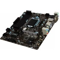
Thank you for choosing the C847IS-P33/C807IS-P33 series (MS-7836 v1.x) Mini-ITX mainboard. The C847IS-P33/C807IS-P33 series is design based on Intel® Celeron 847/807 processor and Intel® NM70 chipset. The C847IS-P33/C807IS-P33 series deliver a high performance and energy saving solution for BOX PCs.

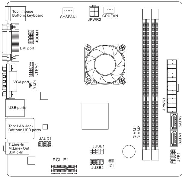
Layout
SPECIFICATIONS
Processor
Intel® Celeron 847/1.1 GHz/Dual-Core processor (C847IS-P33)
Intel® Celeron 807/1.5 GHz/ Single-Core processor (C807IS-P33)
Chipset
Intel® NM70 chipset
Memory Support
2x DDR3 DIMMs support DDR3 1333/ 1066 DRAM (16GB Max)
Supports Dual-Channel mode
LAN
Supports LAN 10/100/1000 Fast Ethernet by Realtek® RTL8111E
Audio
Integrated HD audio codec by Realtek® ALC887
SATA
1x SATA 3Gb/s port by Intel® NM70
1x SATA 6Gb/s port by Intel® NM70
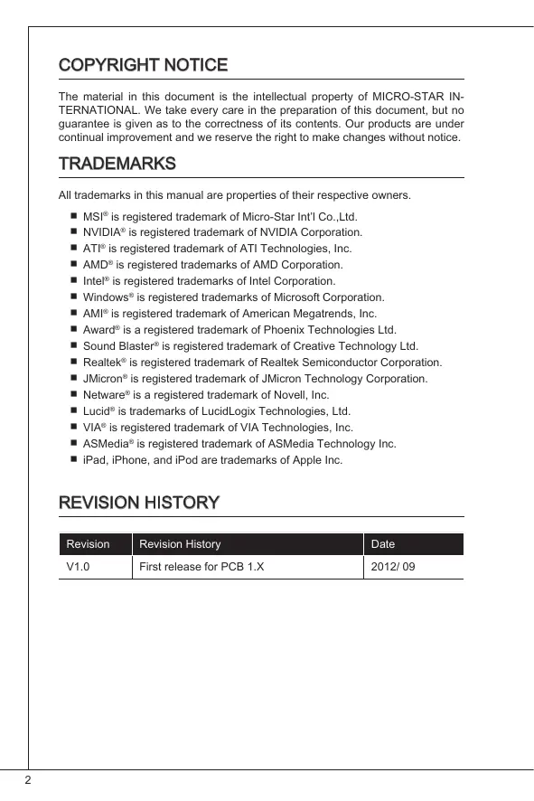
Connectors & Buttons
Back panel
- 1x PS/2 keyboard port
- 1x PS/2 mouse port
- 4x USB 2.0 ports
- 1x LAN port
- 1x VGA port
- 1x DVI-D port
- 3x Audio ports
On-Board
- 2x USB 2.0 connectors
- 1x Front Panel Audio connector
- 1x TPM Module connector
- 1x Serial connector
- 1x Chassis Intrusion connector
Slots
1x PCIe 2.0 x1 slot
Form Factor
- Mini-ITX (17.0 cm X 17.0 cm)
Mounting Screw Holes
4x mounting holes
REAR PANEL
The rear panel provides the following connectors:

IMPORTANT
To reach the 8-channel sound effect, the 7th and 8th channels must be output from front panel.

For more information on compatible components, please visit http://www.msi.com/service/test-report
If you need to purchase accessories and request the part numbers, you could search the product web page and find details on our web address below http://www.msi.com/index.php
Mounting Screw Holes
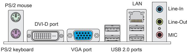
When installing the mainboard, first install the necessary mounting stands required for a mainboard on the mounting plate in your computer case. If there is an I/O back plate that came with the computer case, please replace it with the I/O backplate that came with the mainboard package. The I/O backplate should snap easily into the computer case without the need for any screws. Align the mounting plate's mounting stands with the screw holes on the mainboard and secure the mainboard with the screws provided with your computer case. The locations of the screw holes on the mainboard are shown below. For more information, please refer to the manual that came with the computer case.

IMPORTANT
- Install the mainboard on a flat surface free from unnecessary debris.
- To prevent damage to the mainboard, any contact between the mainboard circuitry and the computer case, except for the mounting stands, is prohibited.
- Please make sure there are no loose metal components on the mainboard or within the computer case that may cause a short circuit of the mainboard.
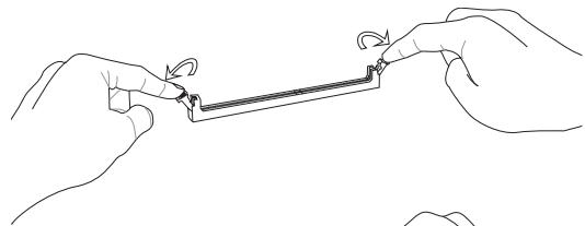
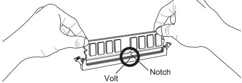
Installing Memory Modules
- Unlock the DIMM slot by pushing the mounting clips to the side. Vertically insert the memory module into the DIMM slot. The memory module has an off-center notch on the bottom that will only allow it to fit one way into the DIMM slot.
- Push the memory module deep into the DIMM slot. The plastic clips at each side of the DIMM slot will automatically close when the memory module is properly seat and an audible click should be heard.
- Manually check if the memory module has been locked in place by the DIMM slot's side clips.


IMPORTANT
- To ensure system stability, memory modules must be of the same type and density in Dual-Channel mode.
- Due to the hardware limitation, you should follow the installing procedures: first memory modules, then graphics card. While uninstalling, remove graphics card first if necessary.
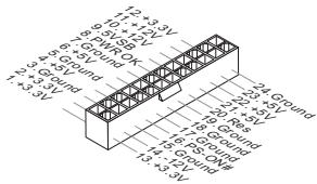
JPWR1:ATX24-Pin Power Connector
This connector allows you to connect an ATX 24-pin power supply. To connect the ATX 24-pin power supply, align the power supply cable with the connector and firmly press the cable into the connector. If done correctly, the clip on the power cable should be hooked on the mainboard's power connector.

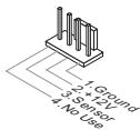
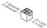
JPWR2:ATX4-Pin Power Connector
This connector provides 12V power to the CPU.
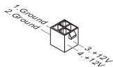

IMPORTANT
Make sure that all the power cables are securely connected to a proper ATX power supply to ensure stable operation of the mainboard.
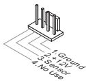
CPUFAN, SYSFAN1: Fan Power Connectors
The fan power connectors support system cooling fans with +12V. If the mainboard has a System Hardware Monitor chipset on-board, you must use a specially designed fan with a speed sensor to take advantage of the CPU fan control. Remember to connect all system fans. Some system fans may not connect to the mainboard and will instead connect to the power supply directly. A system fan can be plugged into any available system fan connector.
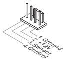
CPUFAN
SYSFAN1
SATA1~2: SATA Connector
This connector is a high-speed Serial ATA interface port. Each connector can connect to one Serial ATA device. Serial ATA devices include disk drives (HD), solid state drives (SSD), and optical drives (CD/DVD/Blu-Ray).

SATA1 (6Gb/s, by Intel® NM70)
SATA2 (3Gb/s, by Intel® NM70)

IMPORTANT
- Please do not fold the SATA cable at a 90-degree angle. Data loss may result during transmission otherwise.
- SATA cables have identical plugs on either sides of the cable. However, it is recommended that the flat connector be connected to the mainboard for space saving purposes.
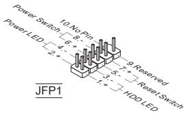
JFP1: Front Panel Connector
These connectors are for electrical connection to the front panel switches and LEDs. The JFP1 is compliant with Intel® Front Panel I/O Connectivity Design Guide.
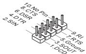
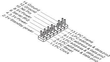
JCOM1: Serial Port Connector
This connector is a 16550A high speed communication port that sends/receives 16 bytes FIFOs. You can attach a serial device.
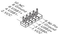
JUSB1, JUSB2: USB 2.0 Expansion Connectors
This connector is designed for connecting high-speed USB peripherals such as USB HD s, digital cameras, MP3 players, printers, modems, and many others.
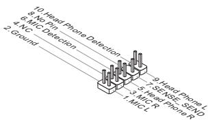
JAUD1 : Front Panel Audio Connector
This connector allows you to connect the front audio panel located on your computer case. This connector is compliant with the Intel® Front Panel I/O Connectivity Design Guide.
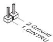
JCI1: Chassis Intrusion Connector
This connector connects to the chassis intrusion switch cable. If the computer case is opened, the chassis intrusion mechanism will be activated. The system will record this intrusion and a warning message will flash on screen. To clear the warning, you must enter the BIOS utility and clear the record.
JTPM1: TPM Module Connector
This connector connects to a optional TPM (Trusted Platform Module). Please refer to the TPM security platform manual for more details and usages.
JBAT1: Clear CMOS Jumper
There is CMOS RAM onboard that is external powered from a battery located on the mainboard to save system configuration data. With the CMOS RAM, the system can automatically boot into the operating system (OS) every time it is turned on. If you want to clear the system configuration, set the jumper to clear the CMOS RAM.

Keep Data

Clear Data

IMPORTANT
You can clear the CMOS RAM by shorting this jumper while the system is off. Afterwards, open the jumper. Do not clear the CMOS RAM while the system is on because it will damage the mainboard.
PCIe Slot
The PCIe slot supports the PCIe interface expansion card.

The PCIe 2.0 x1 slot
BIOS SETUP
Power on the computer and the system will start POST (Power On Self Test) process. When the message below appears on the screen, press key to enter Setup.
Press DEL to enter Setup Menu
If the message disappears before you respond and you still wish to enter Setup, restart the system by turning it OFF and On or pressing the RESET button. You may also restart the system by simultaneously pressing
The Menu Bar
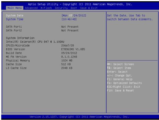
Main Menu
Use this menu for basic system configurations, such as time, date etc.
Advanced
Use this menu to set up the items of special enhanced features.
M-Flash
Use this menu to read/ flash the BIOS form storage drive (FAT/ FAT32 format only).
Security
Use this menu to set supervisor and user passwords.
Boot
Use this menu to specify the priority of boot devices.
Save & Exit
This menu allows you to load the BIOS default values or factory default settings into the BIOS and exit the BIOS setup utility with or without changes.
Save & Exit
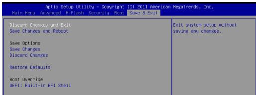
Discard Changes and Exit
Use this item to abandon all changes and exit setup.
Save Changes and Reboot
Use this item to save changes and reset the system.
Save Changes
Use this item to save changes.
Discard Changes
Use this item to abandon all changes.
Restore Defaults
Use this item to load the optimized default values set by the BIOS vendor.
= = Boot Override = =
The installed storage devices will appear on this menu, you can select one of them be a boot device.
INSTALL WINDOWS XP NOTES
This section describes how to install Windows XP with IDE mode.
Installing Windows XP with IDE Mode
You will fail and encounter a blue screen while installing Windows XP, because it is not natively supported to be installed in the storage device with AHCI mode. If you still prefer to install Windows XP as the operating system, please change the BIOS item as below.
- Refer to BIOS SETUP chapter to access BIOS.
- Go to Advanced SATA Mode.
- Set the SATA Mode to IDE mode.
- Go to Save & Exit Save Changes and Reboot.
- Install the Windows XP operating system.
韓國兒
#
C847IS-P33/C807IS-P33 SIRIUS (MS-7836 v1.x) Mini-ITX Emi-in-Brodt zu krieknne du stckrtne au.
suerungen. C847IS-P33/C807IS-P33 SIRIUS is Intel® Celeron 847/807 Pro
roche�e und Intel® NM700 垂世界第一,已将不能在该。C847IS-P33/C807IS-P33 SIRIUS is BOX PC上公信通和告终前的
ReiHaJ
#
J
HD OukiO KoIeK Realtek ALC887 NcT
SATA
Intel® NM70〇或SATA 3Gb/s 1串串机
Intel® NM70〇〇〇 SATA 6Gb/s 1兆贝
K
-
-PS/2引三元1
- PS/2 叶云s 1
- USB 2.0 手电 4 个
LAN互连1个
- VGA 12
- DVI-D 1
- OukiO FIOI 3
Discard Changes and Exit
i
Save Changes and Reboot
Discard Changes and Exit
Mini-ITX (17,0 cm × 17,0 cm)
Discard Changes and Exit

KOMHOENTbI CNCTEMHOI NaTbI
XAPAKTEPNUCTIKN
Ipoedepkka Ppoecccopob
- Ppoceccop Intel® Celeron 847/1.1 ΓΓu/Дыухяерный (C847IS-P33)
- Празецсор Int'l Celeron 807/1.5 ГИОДноаерны (C807IS-P33)
Unncet
Intel®NM70
PamrTb
2x DDR3 DIMMs c noidepkkmo MOnye DDR3 1333/1066 DRAM (MAKcMaHbNaEKMocbT616F)
IopndepkKa dByxKaHaJIbHoro peKIma
LAN
ПодэржкALAN10/100/1000Fast EthernethaochoRealtekRTL8111E
Aydno
BcTpoeHHbH HD aydnoKOeK Realtek® ALC887
SATA
1x nopT SATA 3Γ6/c ha qunncete Intel® NM70
1x nopT SATA 6Γ6/c ha yinceTe Intel® NM70
Pa3bEmbl N KhoNk
3aDne nanei
- 1x PS/2 nopT KnaBnAtypbl
- 1xPS/2nopTmbiH
- 4x nopTa USB 2.0
- 1x nopT LAN
- 1x nopT VGA
- 1x nopT DVI-D
- 3X 3ByKObbl pa3beMa
Pa3bembl Ha nnaTe
- 2x pa3bema USB 2.0
- 1x aydnopazbem Ha nepedne nahei
- 1x pa3bem moyyn TPM
- 1x pa3bem nocneIOBATEbHoro
- 1x pa3bem DaTUnKa OTKpbBaHnK KOpnyCa
Cnotbl
1x cnot PCIe 2.0 x1
ΦopM-ΦaKTop
- Mini-ITX (17.0 cm X 17.0 cm)
OTBepCTNIOyCTaHOBOUHbE BnHTbl
OTBepCTnIy yCTaHOBOUHbIe BNHTbl
Pn yctahOBKe MATEPHCKOIN PnATb Chayana yctAHOBIOte Nbe OeXoDmHBe DnA MATEPHCKOINaTb HOKKn Ha aCCsN B CNTTEMHom 6Noke. EcnN K CTTEMHOmy 6NoKy pnrnaeratea3aDHnra naHeB npOTB BBODa/BbBODa, 3aMeHNe ee naeHbTo, BxOJauSe B KOMNIET MATEPHCKOIN PnATb. 3a NaHeB NERKO paaMeeTaC B CNTTEMHO n 6Noke n He TpeBeyf qHKCaunn BVHTMa. CoMBeNTe HOKKn WACCn COTEPCTMI IN BnHTOB HA MATEPHCKOIN PnATne I 3aKpENITE MATEPHHCyO NAty BNtAMn, PnirnaAOUIMMC R CNTTEMHOmy 6NoKy. PacNOXeHne OTBcTmN NOKPENKHe BnTHb Ma HATEPHCKOIN PnATne Noka3Ho NHe. DOnONJIeBHe bCBeDEHm C. B yPKOBOCTBe K CNTTEMHOmy 6NoKy.


BHIMAHHE
* YCTAHOBKY MATEPHNCKO IINaTbI CNDEYET BByIOJIHTb HA POBHNOBEPXHOCTN, ONUCHENOH OT MYCOPA.
*Bo n36EzHAne NOBpEzDHeN MaTePnHcKo INaTbI, ee 3NeKtpuYecka Cx6Ma HeOnJhKa cOpNkacatcbc C cntEmMbIM 6NoKOM. 3To DoCTHnAeTc C nOmoCbIO HOXEK JyraYctaHOBKn.
* PnOBeBpTe NaHdEJIbCTb 3aKpENIIeHb CEx MTeaIINueCckHX DetanEn Ha MaTePHNcKO nPATA N BHTpyn CInCTemHOro 6bKa. B npOTNBmO hcyae MoKet BO3HNKHyTb KOPOTKoe 3aMbKAHn IN POBPEQdHneMaTEPHCNK O nPbTa.
YctaHOBkaMOdyneiNamrTn
- P36nKpyte DIMM cnot, p3BEda 3axmbl B ctopohb. BCTabBeMoynb namTn B cNOT DIMM BEpTKkAHLbo.Ha MoDyJe nAmTn NmEeTCr CMeUeHNHaor CEHTPBA BlyEMKa BH3y, 6NaIqOApa KOTOPo ero MOXHO BCTABNTB rHe3do DIMM toIbKO onpeJeHbIM o6paOM.
- BCTABTE MOyIb NamaTb C nOTDIM Do ynpa. Ipn npabnHoiy YcAHOBKe MOpIy,PiACTIKOBBe 3aKIMbI c 6OxNtC TOpOH OT cNOTa, ATOMaTHUeCKE 3aKPOHTcC x XapakTePHbM 1eJIYKOM.
- BpyyHyo y6eMntecb, cTO mOyIb 3aKpeIeB C note DIMM 3aueIkamc C oEHX CTOpOH.

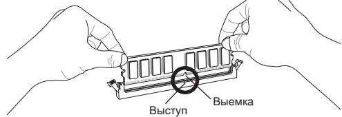
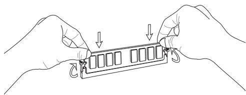

BHIMAHHE
A Dn 06e3eueHnTcBbHOB pa6bTo cIcTeMbI cnONKbI cNcONbO8bTaBC MOyUINTHAHN ODNHO TnN uDNHKOBoEMKOTC.
* B CB83n C annapaTHbIMN ORpAHueHEnrMaN, BblIOINHTe CJIeDyUHne INHCTpyKuMn no yctahOBke: Chauana yctaHOBIne MoDyInn NamraN, 3atEm BnDEoekapTy. PnP BblIOHNHeHH NEMOHTaxa npn HeO6XODmOCTn Chauana N3BNeKeNt BeDkoekapTy.
JPWR1: 24-KoHTaKTHbI pa3bEm nITaHnA ATX
3TOT pa3bem nO3BOJnREt PNOKIOHUYtB 24-KoHTAKTHbI pya3bem pNTAHNA ATX. Pered npOIOKHOeHEMN CTOUHKA NpTAHNAY b6EaITbc8, YTOER OKOHTAKTBI pA3bem Ha nPATE npABINb HO copENTnPOBaHbI. 3ATm NIOTHO BCTaBte ERO B pA3bem HA CTHEMHO nPate. Pn PpABINbMOB HbIOINHNEHN COEINHNEHN, PHKcATOp Ha CNIOBOM KAbene DOJIXEN 3ZAKpeniTB Ka6eNB Ipa3beme MaTePHNCKO nnAbl.
JPWR2:4-KoHTaKTHbIpa3bEmnITaHnATX
3ToTpa3bEmncnoIb3yETcIdIobecneueHnIITaHnIpoceccopa(12Bt).

BHIMAHHE
Y6eIntecb, yTO Bce pa3bembl nHTaHn ATx npabunbHO noDKIOueHbI.
CPUFAN, SYSFAN1: Pa3bEmbl nItaHnBEHTIJIrTOPOB
Bpa3eMbI pINTAHIN DANBEHTUNLTOPOB pa3peWaaTc yUaHOBKa BEHTINLTOPOB C pINTAHNEM +12 B.EcNHa cNCTHMNO PNTAE MNEETC YNCET MoNTOPC NCTMHOO 6ObyoAHNA, Bb DOxKbH bICN0N3ObaTc CneuAInbHo pa3pa6oTaHHbY BEHTINLTOPOC DaATCNOM CKOPOCTN, YTObI bICN0N3OBAbTb UyPAJIeHHe BEHTINLTOPO mpoceccopa. He 3abSyBe TPOKnIOVHTB BCE cNCTHMble BEHTINLTOPOB. HeKOTOpBie cNCTHMble BEHTINLTOPOB HeBO3MOXHO POKNIOVHTB K cNCTHMNO PnATE.BMeCTO 3TOO OH NDOKNIOVAOTCR N ICTOHTNKY PBHTAHNO HAnPryMo. BEHTINLTO MOKET 6bITb NOKIIQUEHEN K IIO6OMY CBOOJHOYM OPA3eMy BEHTINLTOPOA cNCTEMbl.

CPUFAN
SYSFAN1
SATA1~2:Pa3bem ATA
| Audit Setup Utility - Copyright (C) 2011 American Megatrends, Inc. | |
| Main Menu Advanced H-Flash Security, Boot Save & Exit | |
| Discard Changes and ExitSave Changes and RebootSave OptionsSave ChangesDiscard ChangesRestore DefaultsBoot OverrideUEFI: Built-In EFI Shell | Exit systen setup withoutsaving any changes. |
Discard Changes and Exit
Discard Changes and Exit
使用此选项来放弃所有更改并退出设置。
Save Changes and Reboot
使用此选项来保存更改并重启系统。
Save Changes
使用此选项来保存更改。
Discard Changes
使用此选项来放弃所有更改。
Restore Defaults
1個PCIe 2.0× 1 插槽
尺寸
| Optic Setup Utility - Copyright (C) 2011 American Megatrends, Inc. | |
| Main Menu Advanced H-Flash Security Boot Save & Exit | |
| Discard Changes and ExitSave Changes and RebootSave OptionsSave ChangesDiscard ChangesRestore DefaultsBoot OverrideUEFI: Built-In EFI Shell | Exit system setup withoutsaving any changes. |
Discard Changes and Exit
本項用以放棄所有變更及離開設定畫面。
Save Changes and Reboot
本項用以儲存變更後重開機。
Save Changes
本項用以儲存變更。
Discard Changes
本項用以放棄所有變更。
Restore Defaults
Discard Changes and Exit
变更丶設定值を保存せす終了しま�。