MONTE CARLO TCM 169 - Pregnant BLAUPUNKT - Free user manual and instructions
Find the device manual for free MONTE CARLO TCM 169 BLAUPUNKT in PDF.
| Product type | Blaupunkt Monte Carlo TCM 169 car radio |
| Dimensions (W x H x D) | 162 x 53 x 165 mm (DIN recess) |
| Weight | Approximately 0.8 kg |
| Power supply | 12 V DC, permanent (terminal 30) and switched (terminal 15) |
| Output power | 4 x 35 W max (4 Ω) |
| Speaker impedance | 4 Ω |
| Antenna | Radio, telephone, GPS (depending on equipment) |
| Steering wheel remote control compatibility | Yes (with suitable interface) |
| Hands-free kit | Built-in or external microphone (optional) |
| Connectors | ISO connectors, antenna output, microphone input |
| Lighting | Can be connected to dashboard lighting |
| Control cable | Switched + output for motor antenna (max 150 mA) |
| Cable cross-section | Min 1.5 mm² for + and ground cable |
| Fuse | Safety holder on + cable (type to be confirmed) |
| Installation | DIN recess 162x53x165 mm, panel thickness 1-20 mm |
| Supplied accessories | Universal ISO adapter cable, speaker cable, mounting sleeve, disassembly brackets |
| Maintenance | Clean with a soft, dry cloth. Do not use abrasive products. |
| Safety instructions | Disconnect battery before installation, observe polarity and cable cross-section |
| Spare parts | Available from Blaupunkt dealer |
Frequently Asked Questions - MONTE CARLO TCM 169 BLAUPUNKT
User questions about MONTE CARLO TCM 169 BLAUPUNKT
0 question about this device. Answer the ones you know or ask your own.
Ask a new question about this device
Download the instructions for your Pregnant in PDF format for free! Find your manual MONTE CARLO TCM 169 - BLAUPUNKT and take your electronic device back in hand. On this page are published all the documents necessary for the use of your device. MONTE CARLO TCM 169 by BLAUPUNKT.
USER MANUAL MONTE CARLO TCM 169 BLAUPUNKT
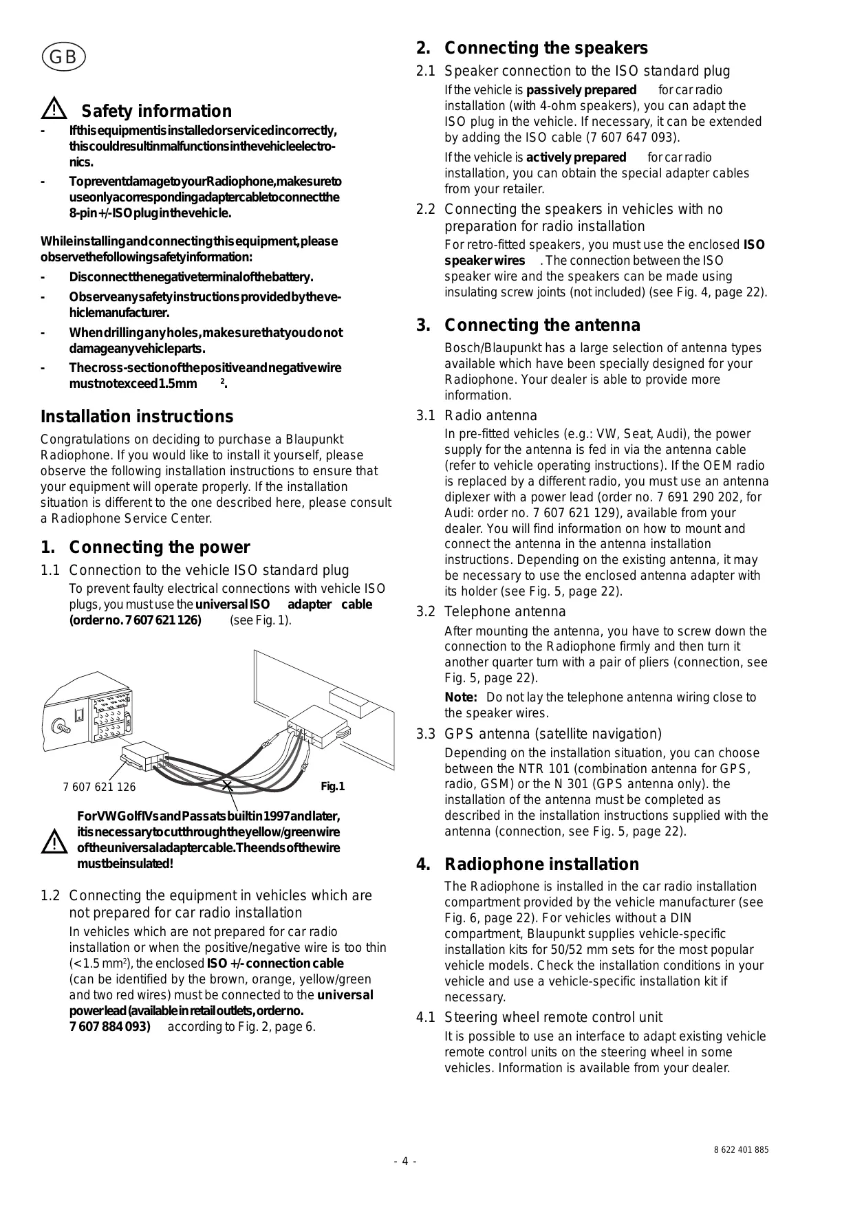
Whileinstallingandconnectingthisequipment,please observethefollowingsafetyinformation:
- Disconnectthenegativeveterinalofthebattery.
- Observeanysafetyinstructionsprovidedbythe vehicle manufacturer.
- Whendrilling anyholes, makesurethatyoudonot damageanyvehicleparts.
- Thecross-sectionofthepositiveandnegativewire mustnotexceed1.5mm 2.
Installation instructions
Congratulations on deciding to purchase a Blaupunkt Radiophone. If you would like to install it yourself, please observe the following installation instructions to ensure that your equipment will operate properly. If the installation situation is different to the one described here, please consult a Radiophone Service Center.
1. Connecting the power
1.1 Connection to the vehicle ISO standard plug To prevent faulty electrical connections with vehicle ISO plugs, you must use the universalISO adapter cable (order no. 7607621 126) (see Fig. 1).
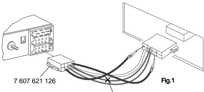

For VWGolfVsand Passatsbuiltin 1997 and later, itisnecessarytocutthroughtheyellow/greenwire oftheuniversaladapter cable. Theendsoftthewire mustbeinsulated!
1.2 Connecting the equipment in vehicles which are not prepared for car radio installation In vehicles which are not prepared for car radio installation or when the positive/negative wire is too thin (< 1.5mm^2) , the enclosed ISO +/- connection cable (can be identified by the brown, orange, yellow/green and two red wires) must be connected to the universal power lead (available in retail outlets, order no. 7607884093) according to Fig. 2, page 6.
2. Connecting the speakers
2.1 Speaker connection to the ISO standard plug If the vehicle is passively prepared for car radio installation (with 4-ohm speakers), you can adapt the ISO plug in the vehicle. If necessary, it can be extended by adding the ISO cable (7 607 647 093). If the vehicle is actively prepared for car radio installation, you can obtain the special adapter cables from your retailer.
2.2 Connecting the speakers in vehicles with no preparation for radio installation For retro-fitted speakers, you must use the enclosed ISO speaker wires . The connection between the ISO speaker wire and the speakers can be made using insulating screw joints (not included) (see Fig. 4, page 22).
3. Connecting the antenna
Bosch/Blaupunkt has a large selection of antenna types available which have been specially designed for your Radiophone. Your dealer is able to provide more information.
3.1 Radio antenna
In pre-fitted vehicles (e.g.: VW, Seat, Audi), the power supply for the antenna is fed in via the antenna cable (refer to vehicle operating instructions). If the OEM radio is replaced by a different radio, you must use an antenna diplexer with a power lead (order no. 7 691 290 202, for Audi: order no. 7 607 621 129), available from your dealer. You will find information on how to mount and connect the antenna in the antenna installation instructions. Depending on the existing antenna, it may be necessary to use the enclosed antenna adapter with its holder (see Fig. 5, page 22).
3.2 Telephone antenna
After mounting the antenna, you have to screw down the connection to the Radiophone firmly and then turn it another quarter turn with a pair of pliers (connection, see Fig. 5, page 22).
Note: Do not lay the telephone antenna wiring close to the speaker wires.
3.3 GPS antenna (satellite navigation)
Depending on the installation situation, you can choose between the NTR 101 (combination antenna for GPS, radio, GSM) or the N 301 (GPS antenna only). The installation of the antenna must be completed as described in the installation instructions supplied with the antenna (connection, see Fig. 5, page 22).
4. Radiophone installation
The Radiophone is installed in the car radio installation compartment provided by the vehicle manufacturer (see Fig. 6, page 22). For vehicles without a DIN compartment, Blaupunkt supplies vehicle-specific installation kits for 50 / 52mm sets for the most popular vehicle models. Check the installation conditions in your vehicle and use a vehicle-specific installation kit if necessary.
4.1 Steering wheel remote control unit
It is possible to use an interface to adapt existing vehicle remote control units on the steering wheel in some vehicles. Information is available from your dealer.
4.2 Installing the mounting bracket
The mounting bracket included with this Radiophone allows you to install the Radiophone in vehicles with DIN compartments measuring 182 × 53 × 185 mm and with an instrument panel thickness of 1 to 20 mm in the area of the tab fasteners (see Fig. 1, page 4). To install the mounting bracket, insert it into the compartment and see which tab fasteners you can bend over with a screwdriver (see Fig. 7, page 22).
Note: Bend as many of the tab fasteners as possible.
4.3 Installing the Radiophone
Push all of the plugs into the sockets until they lock in at the sides. Then insert the Radiophone into the mounting bracket from the front. Gently push both sides of the radio into the compartment until the spring locks on the left and right snap into place (you will hear an audible click).
Important! While inserting the radio, do not press against the display, the buttons or the knobs!
4.4 Removing the Radiophone
Insert the handles into the holes in the panel on the left and right of the radio and push them in until you hear a distinct click (unlocks side springs). Pull the unit out carefully using both handles. Now you can remove the connection cables by pressing the spring lock to the side (see Fig. 8, page 22).
Note: Handles which have snapped into place cannot be removed until you have pulled the radio out of the compartment.
5. Connection drawings
Power connection to vehicle ISO standard
plug, Fig. 1 page 4
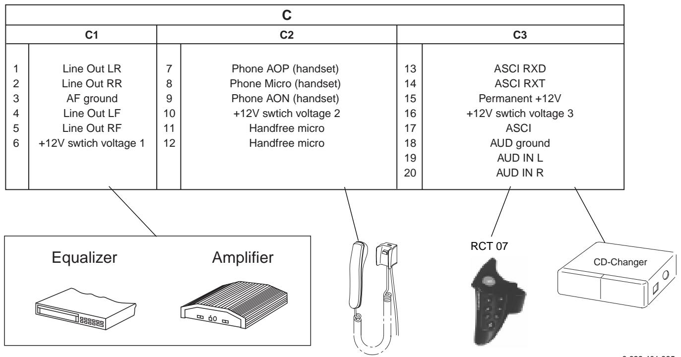
Connection pin allocations, Fig. 2/12 page 6/23
Power connection to vehicle-specific plug,
Fig. 3 page 22
Speaker connections: 4 speakers (4W/35 W),
Fig. 4 page 22
Antenna connection, Fig. 5 page 22
Radiophone installation, Fig. 6/7 page 22
Radiophone removal, Fig. 8 page 22
Universal voltage supply cable, Fig. 9 page 22
Connection with a hands-free microphone,
Fig. 10 page 23
Connection with a telephone handset
(Handset 7 607 570 512), Fig. 11 page 23
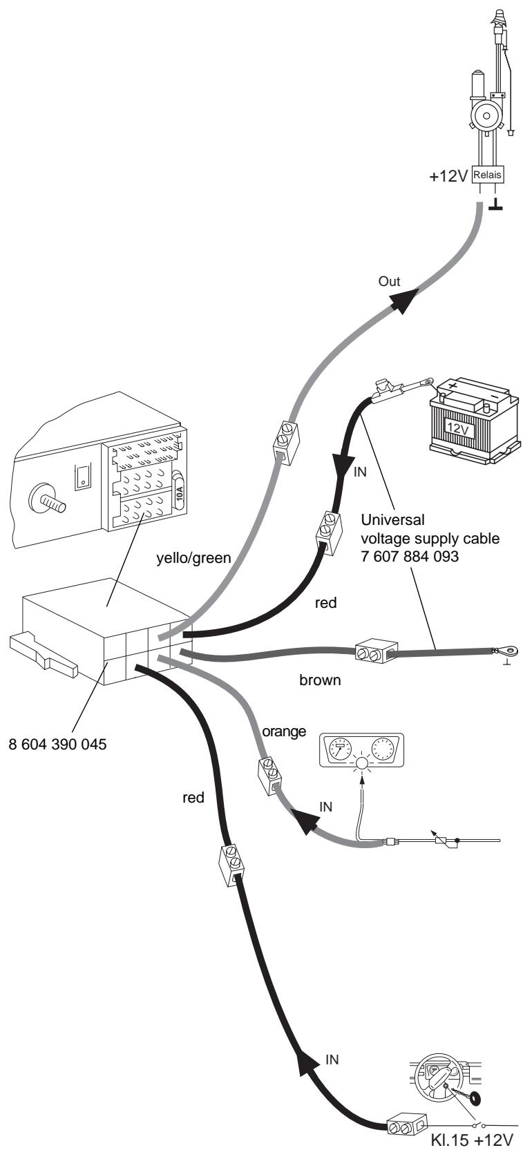
Control cable(Power Antenna+)
The control cable is the connected positive output for external components such as the power antenna, (maximum load < 150mA ).
Important! Do not hook up the control cable to terminal 15 (switched to plus) or terminal 30 (continuous plus).
per. +12V
Continuous plus connection (terminal 30 battery +12 volts)
Lay the positive wire (red/minimum 1.5mm^2 in the cross section) to the battery (not directly along the wire harnesses). Connect the fuse holder to protect the positive wire and connect it to the positive terminal on the battery.

Ground
Do not connect the ground wire (minimum 1.5mm^2 in the cross section) to the negative terminal of the battery. Lay the ground wire to a suitable ground (chassis screw, chassis metal) and screw it down there.

Illuminationconnection
Illumination connection for vehicles with adjustable instrument illumination (plus controlled).
Fig.2
Positive connection (switched via the ignition)
This connection should made to the ignition only (terminal 15).

(borne 30 bateria + 12V)
| A | B | ||
| 1 | — | 1 | Speaker out RR+ |
| 2 | — | 2 | Speaker out RR- |
| 3 | — | 3 | Speaker out RF+ |
| 4 | Ignition | 4 | Speaker out RF- |
| 5 | Aut. antenna | 5 | Speaker out LF+ |
| 6 | Illumination | 6 | Speaker out LF- |
| 7 | Permanent +12V | 7 | Speaker out LR+ |
| 8 | Ground | 8 | Speaker out LR- |