
EVI-D100P - Security Camera SONY - Free user manual and instructions
Find the device manual for free EVI-D100P SONY in PDF.


| Product Type | Security Camera |
| Brand | Sony |
| Model | EVI-D100P |
| Pan/Tilt Range | Pan: 340°, Tilt: +90° to -30° |
| Optical Zoom | 10x |
| Signal System | PAL |
| Image Sensor | 1/4" CCD |
| Horizontal Resolution | 480 TV lines |
| Minimum Illumination | 0.7 lux (F1.8) |
| Video Output | Composite (BNC), S-Video |
| Control Interface | RS-232C/422 |
| Power Supply | DC 10.8-13.2V |
| Power Consumption | 8.4W (max) |
| Dimensions (W x H x D) | 142 x 109 x 164 mm |
| Weight | 1.5 kg |
| Operating Temperature | 0°C to 40°C |
| Mount Options | Ceiling, wall, or desktop |
| Preset Positions | 16 |
| Auto Tracking | Yes (optional) |
| Spare Parts Availability | Contact Sony support for parts |
| Repairability | Modular design, serviceable by qualified technician |
Frequently Asked Questions - EVI-D100P SONY
User questions about EVI-D100P SONY
0 question about this device. Answer the ones you know or ask your own.
Ask a new question about this device
Download the instructions for your Security Camera in PDF format for free! Find your manual EVI-D100P - SONY and take your electronic device back in hand. On this page are published all the documents necessary for the use of your device. EVI-D100P by SONY.
USER MANUAL EVI-D100P SONY
Operating Instructions GB
EVI-D100
EVI-D100P
用户记录
natural_image
Line drawing of a vintage desktop computer with monitor, keyboard, and mouse (no text or symbols)注意
natural_image
Illustration of a hand pressing a button on a device (no text or symbols present)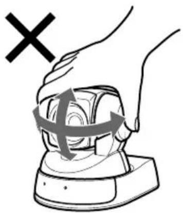
natural_image
Illustration of a hand pressing a button with directional arrows indicating motion (no text or symbols)将摄像机安装到三脚架上
natural_image
Line drawing of a camera mounted on a tripod with a clip, showing no text or symbols连接
natural_image
Line drawing of a mechanical device with a circular top and base (no text or symbols)闪烁
使用遥控器操作摄像机
natural_image
Technical line drawing of a mechanical device with no visible text or symbols使用遥控器操作多个摄像机
natural_image
Technical line drawing of a mechanical device with a close-up inset showing a pin tool interacting with a component (no text or symbols present)维护
The model number and the serial number are located on the bottom exterior.
Record these numbers in the spaces provided below. Refer to these numbers whenever you call upon the dealer regarding this product.
Model No. ____
Serial No. ____
WARNING
To reduce the risk of fire or electric shock, do not expose this apparatus to rain or moisture.
To avoid electrical shock, do not open the cabinet. Refer servicing to qualified personnel only.
This unit has no power switch.
When installing the unit, incorporate a readily accessible disconnect device in the fixed wiring, or connect the power cord to socket-outlet which must be provided near the unit and easily accessible.
If a fault should occur during operation of the unit, operate the disconnect device to switch the power supply off, or disconnect the power cord.
IMPORTANT
The nameplate is located on the bottom.
For customers in the U.S.A.
This equipment has been tested and found to comply with the limits for a Class B digital device, pursuant to Part 15 of the FCC Rules. These limits are designed to provide reasonable protection against harmful interference in a residential installation. This equipment generates, uses, and can radiate radio frequency energy and, if not installed and used in accordance with the instructions, may cause harmful interference to radio communications. However, there is no guarantee that interference will not occur in a particular installation. If this equipment does cause harmful interference to radio or television reception, which can be determined by turning the equipment off and on, the user is encouraged to try to correct the interference by one or more of the following measures:
— Reorient or relocate the receiving antenna.
— Increase the separation between the equipment and receiver.
— Connect the equipment into an outlet on a circuit different from that to which the receiver is connected.
— Consult the dealer or an experienced radio/TV technician for help.
You are cautioned that any changes or modifications not expressly approved in this manual could void your authority to operate this equipment.
All interface cables used to connect peripherals must be shielded in order to comply with the limits for a digital device pursuant to Subpart B of Part 15 of FCC Rules.
If you have any questions about this product, you may call; Sony Customer Information Service Center 1-800-222-7669 or http://www.sony.com/
Declaration of Conformity
Trade Name: SONY
Model : EVI-D100
EVI-D100P
Responsible Party: Sony Electronics Inc.
Address: 16530 Via Esprillo,
San Diego, CA
92127 U.S.A.
Telephone Number: 858-942-2230
This device complies with part 15 of the FCC Rules. Operation is subject to the following two conditions:
(1) this device may not cause harmful interference, and (2) this device must accept any interference received, including interference that may cause undesired operation.
For customers in Canada
This Class B digital apparatus complies with Canadian ICES-003.
The electromagnetic fields at the specific frequencies may degrade the intended performance level of video signals.
For the customers in Netherlands Voor de Klanten in Nederland
Locations of Controls 27
Main Unit 27
Remote Commander 28
Basic Operations
Preparations 30
Installation 30
Connections 32
Turning on the Power 33
Pan/Tilt Operation 34
Adjusting the Camera 36
Having the Camera Memorize the Setting — Presetting feature .... 37
General
Troubleshooting 38
Precautions 39
Brightness of a Subject 39
Avoid Specialized Application 39
Precaution on Copyright 39
About Backup 39
When You Discard Color Video Camera 40
Maintenance 41
Specifications 42
Overview
Features
- The CCD features 380,000 effective picture elements for the EVI-D100 and 440,000 for the EVI-D100P, which enables high-resolution shooting.
- In addition to high-speed pan/tilt action, improvement of the noise reduction mechanism lets you use Color Video Camera for a variety of purposes.
• VISCA lets you operate your Color Video Camera from a computer. - Up to six combinations of the camera's position and status can be memorized.
- A multi-function Remote Commander is provided.
Locations of Controls
For details, see the pages indicated in parenthesis.
Main Unit
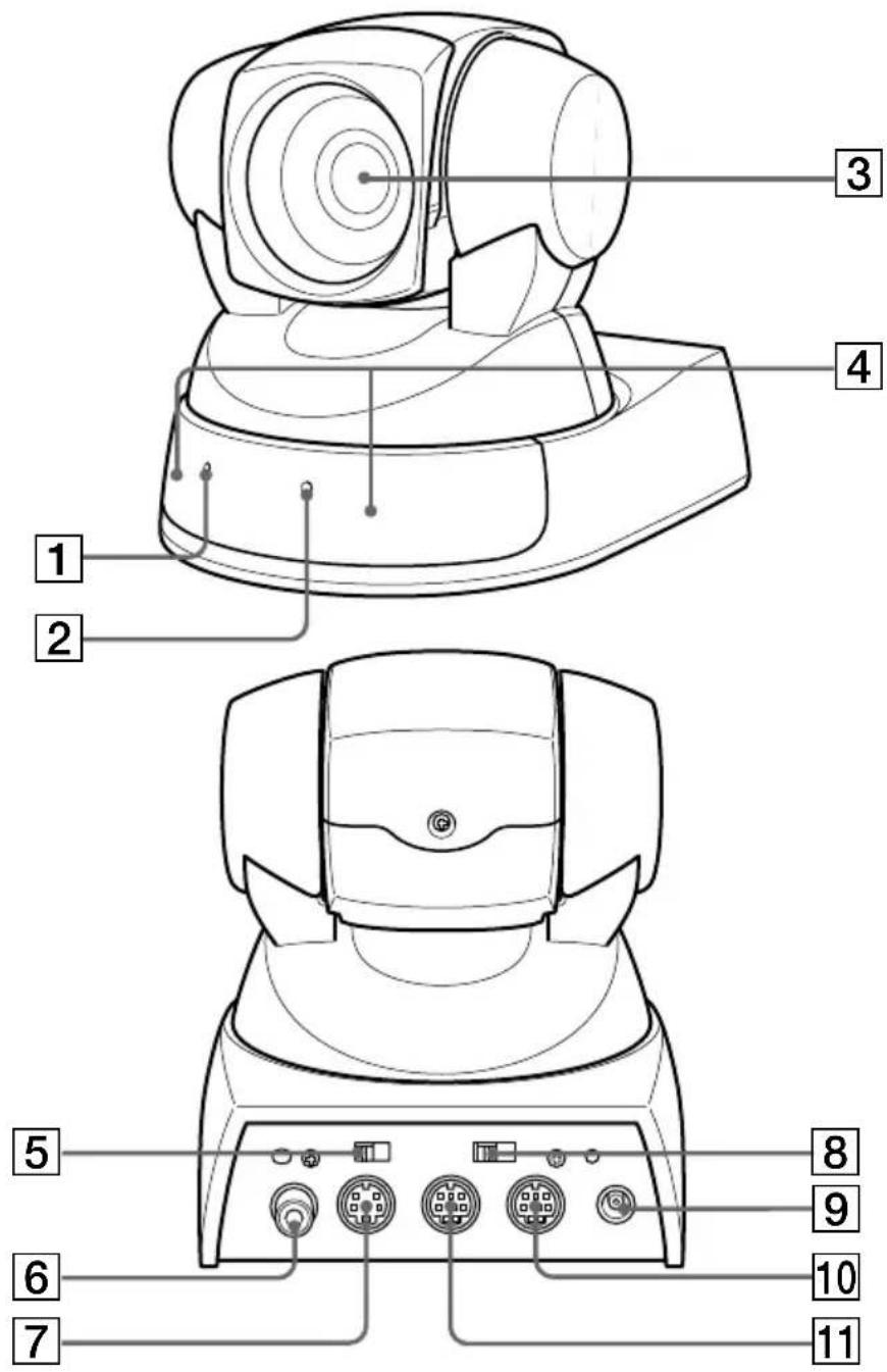
1 POWER lamp (33)
2STANDBY lamp (35)
3 Lens
④ Sensor for the Remote Commander (35)
5BACKUP switch (39)
6VIDEO jack (32)
7 S VIDEO jack (32)
8 IR SELECT switch (35)
9DC IN 12V jack (32)
10 VISCA OUT jack (32)
11 VISCA IN jack (32)
Remote Commander
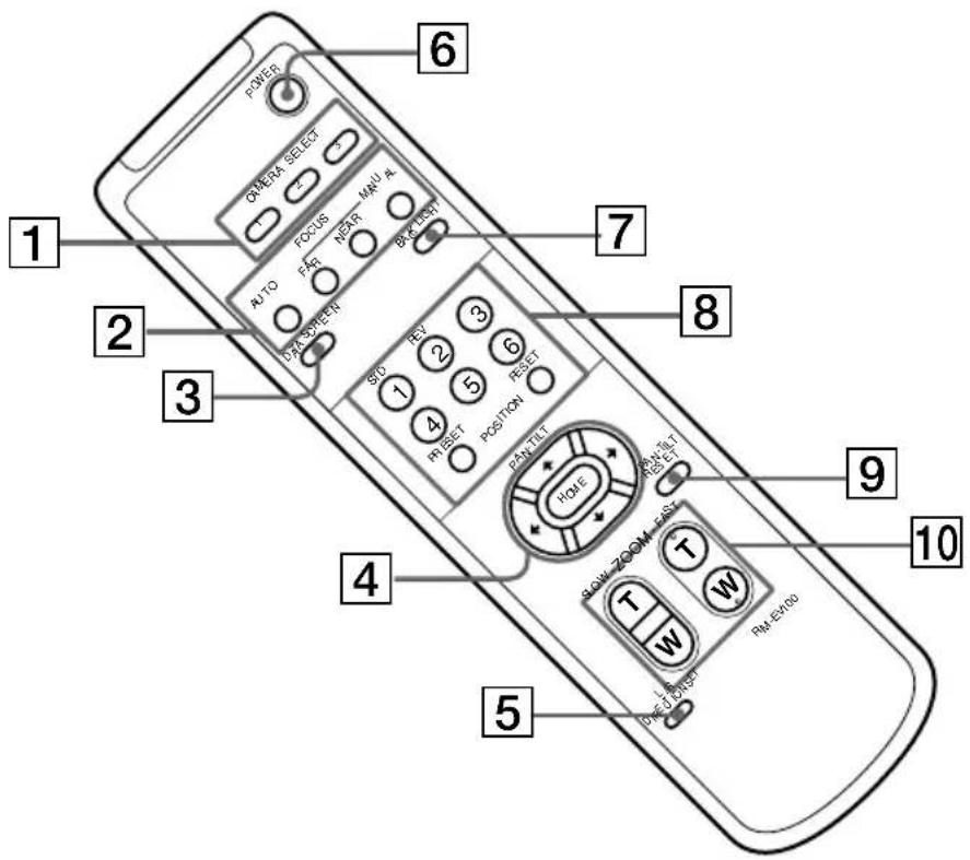
1 CAMERA SELECT buttons (35)
2FOCUS buttons (36)
AUTO button
FAR button
NEAR button
MANUAL button
3 DATA SCREEN button
4PAN-TILT button (34)
Arrow buttons
HOME button
5 L/R DIRECTION SET button (38)
6 POWER switch (33)
7 BACK LIGHT button (36)
8 POSITION buttons (37)
Numeric buttons (Button 1 also works as the STD button. Button 2 also works as the REV button.)
(34)
PRESET button
RESET button
9PAN-TILT RESET button (35)
10 ZOOM buttons (36)
SLOW T button
SLOW W button
FAST T button
FAST W button
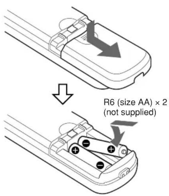
Installing batteries
Basic Operations
Preparations
Installation
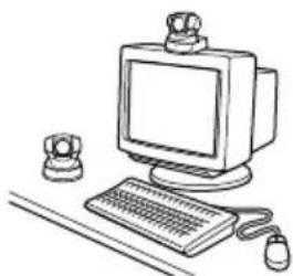
Be sure to place the main unit on a flat surface.
If you must place the camera on an inclined surface, make sure the incline is less than ±15 degrees.
natural_image
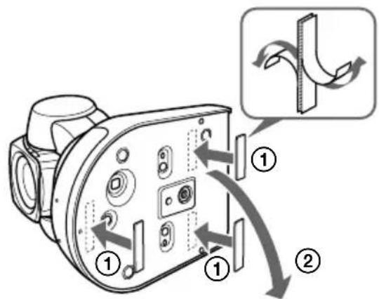
Line drawing of a vintage desktop computer with monitor, keyboard, and mouse (no text or symbols)Secure the camera in place with the supplied Velcro tape.
Notes
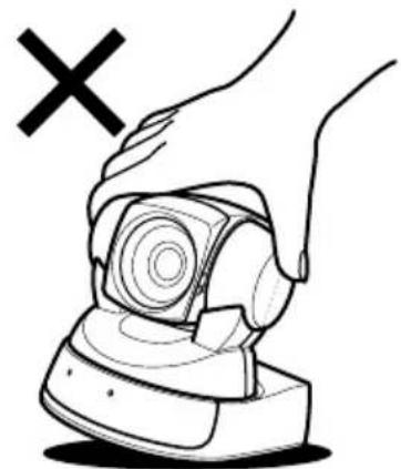
- Do not grasp the camera head when carrying the video camera.
- Do not turn the camera head manually. Doing so will result in the camera malfunctioning.
natural_image
Illustration of a hand pressing a button with a 'X' symbol above (no text or labels)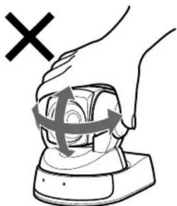
natural_image
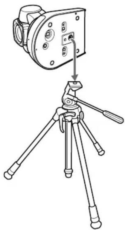
Illustration of a hand pressing a button with a cross mark and X symbol (no text or labels)To attach the camera to a tripod
Use a tripod with screws meeting either of the following specifications.
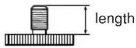
ISO standard: length 4.5 mm ±0.2 mm
ASA standard: length 0.197 inches
natural_image
Line drawing of a camera mounted on a tripod with a clip, showing no text or symbolsConnections
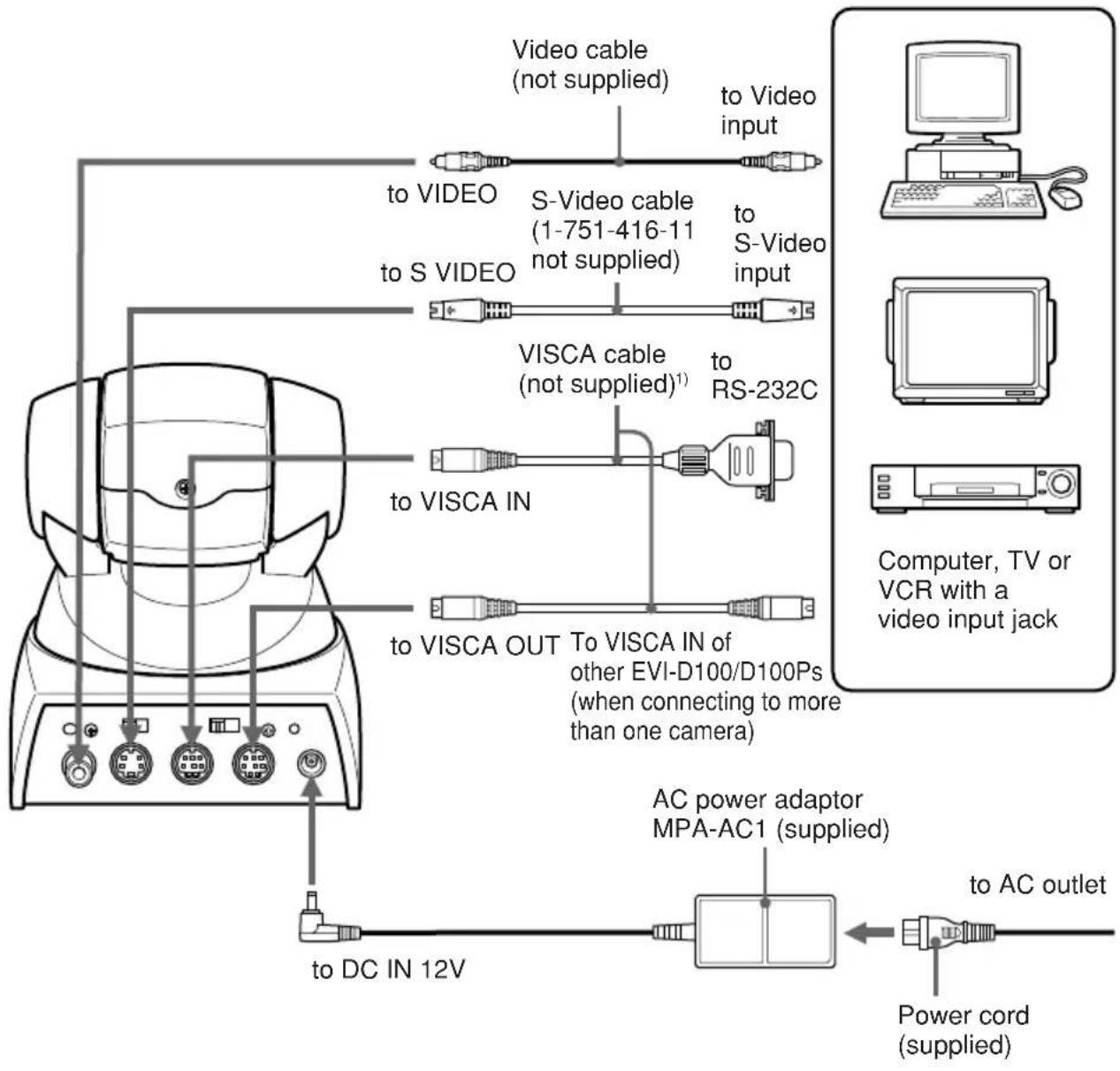
Connect your Color Video Camera to a computer, TV or VCR equipped with a video input. Some connections may require extra cables. Refer to the instruction manual of the equipment to be connected.
flowchart
graph TD
    A["Computer, TV or VCR with a video input jack"] --> B["Video cable (not supplied)"]
    A --> C["S-Video cable (1-751-416-11 not supplied)"]
    A --> D["VISCA cable (not supplied)¹"]
    A --> E["VISCA IN"]
    A --> F["VISCA OUT"]
    A --> G["AC power adaptor MPA-AC1 (supplied)"]
    A --> H["Power cord (supplied)"]
    A --> I["to DC IN 12V"]
    A --> J["to AC outlet"]
1) When the camera is connected to a computer with a VISCA cable (RS-232C, cross type), you can operate the camera with the computer. To obtain a cable, consult the dealer where you bought your camera.
Notes
- You cannot connect your Color Video Camera to a computer that is not equipped with either video input or an S-Video input jack. You might not be able to use your existing computer with your Color Video Camera unless you provide the computer with a video capture board and/or software. Consult your computer dealer or manufacturer for details.
- Use only the AC power adaptor (MPA-AC1) supplied with the unit. Do not use any other AC power adaptor.
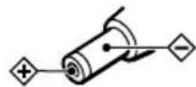
Polarity of the plug
Turning on the Power
1 Connect the main unit to an AC outlet using the supplied AC power adaptor and power cord.
The POWER lamp lights up. As long as the main unit is connected to an AC outlet, you can turn the camera on or off with the POWER switch on the Remote Commander. (When you turn the power off using the Remote Commander, the POWER lamp turns off and the STANDBY lamp lights up.) When the power is turned on, the camera will automatically face first toward the upper left-hand side, and then the front, which is the home position of the camera. (Pan/tilt reset action)
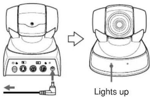
to AC outlet
2 Turn on the peripheral devices.
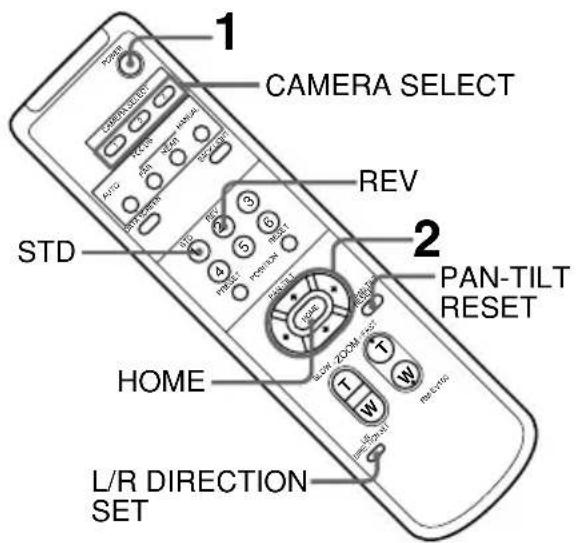
1 Press the POWER switch.
The camera will turn on, performing the pan/tilt reset action automatically.
2 Press the arrow button to change the directions of the camera head.
While checking the picture on the screen, press the desired arrow button.
To move the camera little by little, press the button just for a moment.
To move the camera in a wide range, press and hold down the button.
To move the camera diagonally, press the arrow button (or) while holding down the arrow button (or).
To face the camera back to the front
Press the HOME button.
If you accidentally move the camera head with your hand
Release the camera head immediately to let it return to the previous position automatically. If you move the camera head and hold it over a prolonged period, the camera's power turns off. To turn it back on, press the POWER switch on the Remote Commander.
When the camera is facing in the wrong direction
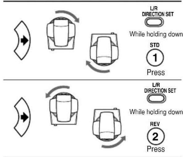
The camera is preset to face toward the right whenever the arrow (💡) button is pressed. You might wish to face the camera toward the opposite direction from that of the button you pressed. In such a case, you can change the direction of the camera while checking the picture on the screen. To do so, press the REV button while holding down the L/R DIRECTION SET button.
To reset that setting, press the STD button while holding down the L/R DIRECTION SET button.
Arrow Movement of Setting button the camera
flowchart
graph TD
    A["Top Left"] --> B["Left Arrow"]
    B --> C["Right Arrow"]
    C --> D["Left Arrow"]
    D --> E["Right Arrow"]
    E --> F["Left Arrow"]
    F --> G["Right Arrow"]
    G --> H["Left Arrow"]
    H --> I["Right Arrow"]
    I --> J["Left Arrow"]
    J --> K["Right Arrow"]
    K --> L["Left Arrow"]
    L --> M["Right Arrow"]
    M --> N["Left Arrow"]
    N --> O["Right Arrow"]
    O --> P["Left Arrow"]
    P --> Q["Right Arrow"]
    Q --> R["Left Arrow"]
    R --> S["Right Arrow"]
    S --> T["Left Arrow"]
    T --> U["Right Arrow"]
    U --> V["Left Arrow"]
    V --> W["Right Arrow"]
    W --> X["Left Arrow"]
    X --> Y["Right Arrow"]
    Y --> Z["Left Arrow"]
Note
Repeat the above-mentioned procedure for each Remote Commander if you are using more than one Remote Commander. This is because the setting is performed by changing the signal emitted from each Remote Commander, not by changing the setting of the camera itself.
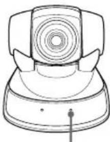
If the STANDBY lamp flashes
The micro computer inside the camera might not memorize the current pan/tilt position properly. Press the PAN-TILT RESET button to reset the pan/tilt position.
natural_image
Line drawing of a vintage rotary dial with a circular head and side blades (no text or symbols)Flashes
Operating the camera with the Remote Commander
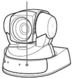
Use the Remote Commander facing it toward the sensor for the Remote Commander. The POWER lamp flashes while the main unit receives a signal from the Remote Commander.
Sensor for the Remote Commander
natural_image
Technical line drawing of a mechanical device with no visible text or symbolsOperating more than one camera with the Remote Commander
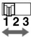
1 Set the IR SELECT switch (at the rear of the main unit) of the camera(s) which you intend to operate to 1, 2 or 3.
2 Press a CAMERA SELECT button (on the Remote Commander) which corresponds to the number set in step 1.
Then, you can operate the camera(s) specified by number. Every time you operate the camera(s) using the Remote Commander, the CAMERA SELECT button pressed in step 2 lights up.
IR SELECT
Adjusting the Camera
Focusing on a subject
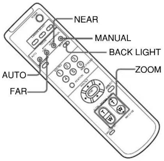
To focus the camera on a subject automatically
Press the AUTO button.
The camera focuses on the subject at the center of the screen automatically.
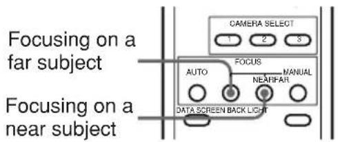
To focus the camera on a subject manually
After pressing the MANUAL button, press either the FAR or the NEAR button to have the camera focus on the subject.
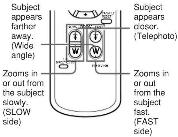
Zooming
Press either of the four ZOOM buttons.
Note
When you perform a pan/tilt operation while the camera is in the telephoto mode, the moving speed of the image on the screen may be a little jerky.
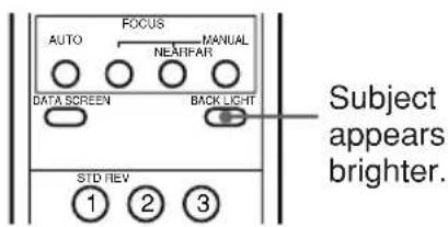
Shooting with back lighting
When you shoot a subject with a light source behind it, the subject becomes dark. In such a case, press the BACK LIGHT button.
To cancel the function, press the BACK LIGHT button again.
Having the Camera Memorize the
Setting — Presetting feature
Up to six combinations of settings (position, zooming, focusing and back lighting) can be preset.
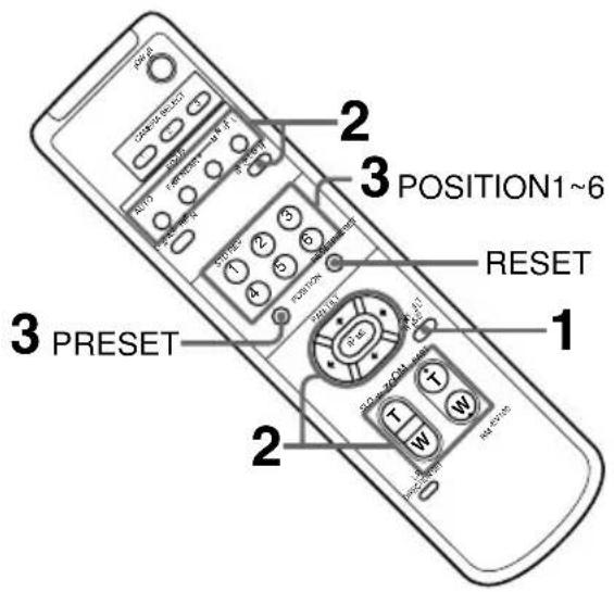
1 Confirm that the STANDBY lamp is not flashing.
If the STANDBY lamp is flashing, press the PAN-TILT REST button to reset the pan/tilt position.
2 Adjust the position, the zooming, the focusing, and the back lighting of the camera. (See pages 34 and 36.)
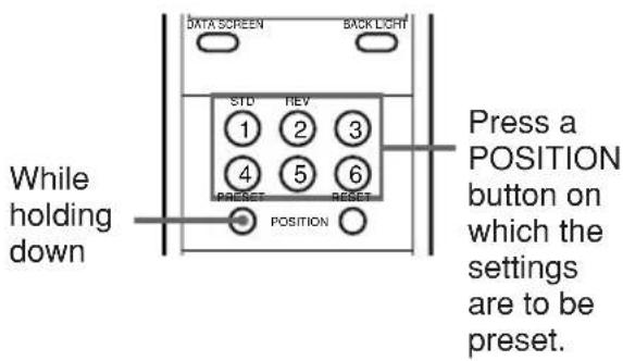
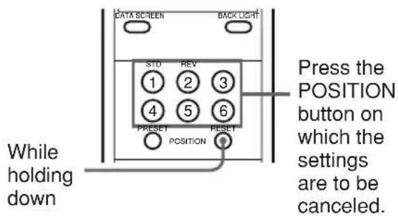
3 While holding down the PRESET button, press any of the POSITION buttons, 1 - 6.
Recalling the memorized setting
Press any of the POSITION buttons 1 – 6 on which your settings have been saved.
Canceling the preset memory
While holding down the RESET button, press the POSITION button on which the settings are to be canceled.
Note
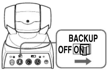
The memorized information is retained until the power of the main unit is turned off. To retain the memory even if the power is turned off, set the BACKUP switch, at the rear of the camera, to ON. (See “About Backup” on page 39.)
General
Troubleshooting
| Symptom | Remedy |
| The picture does not appear on the screen of your computer. | Make sure the connections are made correctly.Test the Color Video Camera by connecting it to other equipment such as a TV or video deck. |
| The picture quality obtained from a Color Video Camera connected to a computer is not good as that from a Color Video Camera connected to a TV. | Depending on your computer or video capture board, you may not be able to obtain the same picture quality as that of a TV. Consult your computer manufacturer or dealer for details. |
| Symptom | Remedy |
| The unit cannot be operated when a button on the Remote Commander is pressed. | Press the CAMERA SELECT button whose number is the same as the number to which the IR SELECT switch of the camera is set.Replace the batteries of the Remote Commander with new ones.Plug in the power cord to an AC outlet. |
| The unit cannot be operated at all. | Pull out the plug of the power cord from the AC outlet, then reinsert it into the AC outlet after a while. If you still cannot operate the unit, set the BACKUP switch (at the rear of the main unit) to OFF and disconnect and reconnect the power cord from the AC outlet. (Note that the settings will be erased when the BACKUP switch is set to OFF.) |
Precautions
After operating the unit with an AC power adaptor, disconnect the AC power adaptor from the wall outlet if the set is not to be used for an extended period of time.
Brightness of a Subject
Color Video Camera might not work at its best in a place where the brightness exceeds the illumination range (such as a place exposed to direct sunlight).
Avoid Specialized Application
- Do not shoot an extremely bright object such as sunlight or a lamp.
- Do not use the camera around a facility which transmits powerful radio waves such as a TV or radio transmitter.
- Do not use the camera under unstable lighting conditions. Otherwise, screen flickering may occur.
Precaution on Copyright
Television programs, pictures, magazines, and other materials may be copyrighted. Unauthorized recording or storing of such materials violates the provision of the copyright laws.
About Backup
Settings such as the camera position are erased when you disconnect the power cord or turn the camera off. To retain those settings, set the BACKUP switch, at the rear of the camera, to ON.
Notes
- In this unit, the built-in lithium battery acts as the power source for retaining the settings and it is kept charged as long as the unit is used. If the unit is used for shorter periods of time with the BACKUP switch set to ON, however, the battery is gradually discharged. If you do not use the unit at all for almost one year, the battery is completely discharged. To retain the settings, you should recharge the battery.
- To recharge the battery, plug in the unit to an AC outlet using the AC power adaptor and the power cord and leave it for approximately 48 hours.
When You Discard Color Video Camera
For environmental reasons, take out the lithium battery from the camera and discard it appropriately.
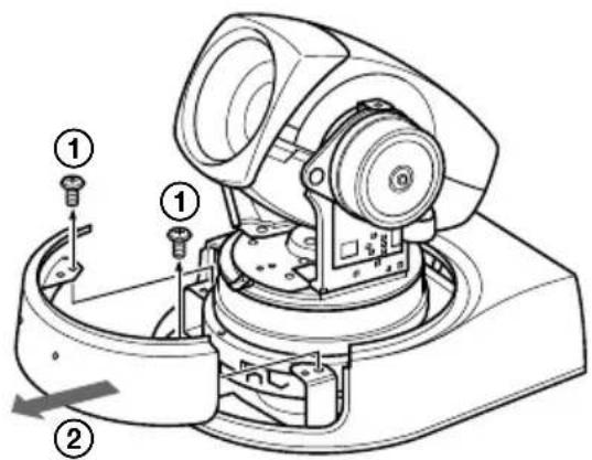
1 Hold the lower part of the pan cabinet (side) with your fingers, and pull it up while stretching it until it comes off.
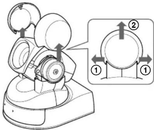
2 While holding both sides of the pan cabinet (front) tight, pull it toward the front. Then, remove the two screws ④ using a Phillips screw driver and detach the pan cabinet (rear).
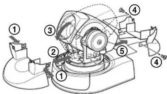
3 Remove the two screws ① and detach the cover of the sensor for the Remote Commander.
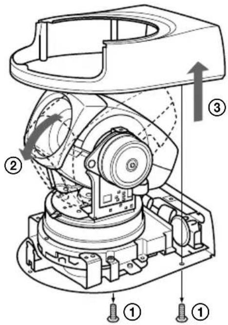
4 Remove the two screws ① and turn the camera head down, then pull the base cabinet up until it comes off.
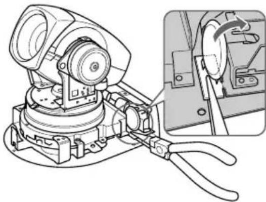
5 Hold the board on which the lithium battery is attached using long-nose pliers. Then, bend it in the direction of the arrow illustrated below to detach the battery.
natural_image
Technical line drawing of a mechanical device with cliers and a close-up inset showing a component being inserted (no text or symbols present)Maintenance
Clean dirt and soil from the cover with a soft cloth or tissue paper.
Cleaning the main unit
- When the body of the camera is dirty, clean it with a soft cloth that is soaked with a diluted neutral detergent and tightly wrung. Then finish with a dry cloth.
- Do not use any type of solvents, which may damage the finish.
- When you use a chemical cloth, follow its instructions.
- Do not sprinkle volatile matter such as pesticide over your Color Video Camera nor allow rubber or vinyl to come in contact with the Color Video Camera for a long period of time. Doing so may damage the finish.
Replacing the batteries of the Remote Commander
If the Remote Commander does not operate from a long distance, the batteries may be worn out. Replace the batteries with new ones (AA × 2).
System
Video signal
EVI-D100: NTSC Color,
JEITA standards
EVI-D100P: PAL Color,
CCIR standards
Picture element
^1/_4 inch color CCD
(Total picture elements:
EVI-D100: Approx.
410,000
EVI-D100P: Approx.
470,000)
(Effective picture elements:
EVI-D100: Approx.
380,000
EVI-D100P: Approx.
440,000)
Lens 10× (Optical), 40× (Digital)
f=3.1 to 31 mm, F1.8 to
F2.9
Horizontal angle: 6.6 to 65
degrees
Minimum object distance
WIDE end : 100 mm
TELE end : 600 mm
Minimum illumination
3.5 lx (F1.8)/with 50 IRE
Illumination range
3.5 to 100,000 lx
Shutter speed
EVI-D100: 1/4 to
1/10,000 s (VISCA
control)
EVI-D100P: 1/3 to
1/10,000 s (VISCA
control)
Horizontal resolution
NTSC : 470 TV (WIDE
end)
PAL : 460 TV (WIDE end)
Video S/N 50 dB
Pan/tilt action
Horizontal: ±100 degrees
Maximum speed:
300 degrees / s,
Vertical: ±25 degrees
Maximum speed:
125 degrees / s
Input/output terminals
Video output
RCA pin jack (1), 1Vpp,
75 ohm unbalanced
Synchronization: negative
S video output
4 pin mini DIN (1)
Input/output control terminals
RS-232C (input: 1,
DC 12 V (DC 10.8 to 13 V)
Current consumption
1.1 A (at 12 V DC)
Operating temperature
0^ to 40^ (32°F to
104 °F)
Storage temperature
-20^ to +60^ (-4^ to
+140 °F)
Dimensions
$$ \begin{array}{l} 1 1 3 \times 1 2 0 \times 1 3 2 \mathrm{mm} \ \left(4 ^ {1} / _ {2} \times 4 ^ {3} / _ {4} \times 5 ^ {1} / _ {4} \text {in.}\right) \ (\mathrm{w} / \mathrm{h} / \mathrm{d}) \ \end{array} $$
Video camera:
Remote Commander:
$$ 5 6 \times 2 6 \times 2 1 0 \mathrm{mm} $$
$$ \left(2 ^ {1} / _ {4} \times 1 ^ {1} / _ {1 6} \times 8 ^ {3} / _ {8} \text {in.}\right) $$
$$ (\mathrm{w} / \mathrm{h} / \mathrm{d}) $$
Mass Video camera:
$$ 8 8 0 \mathrm{g} (1 \mathrm{lb} 1 5 \text { oz . }) $$
Remote Commander:
$$ 1 0 9 \mathrm{g} (3. 8 \text { oz . }) $$
Installation angle
$$ \pm 1 5 \text { degrees to a horizontal } $$
$$ \mathrm{surface} $$
Supplied accessories
AC power adaptor (1)
Power cord (1)
Remote Commander (1)
Velcro tape (3 sets)
Operating Instructions (1)
Design and specifications are subject to change without notice.
Notes
- Always make a test recording, and verify that it was recorded successfully. SONY WILL NOT BE LIABLE FOR DAMAGES OF ANY KIND INCLUDING, BUT NOT LIMITED TO, COMPENSATION OR REIMBURSEMENT ON ACCOUNT OF FAILURE OF THIS UNIT OR ITS RECORDING MEDIA, EXTERNAL STORAGE SYSTEMS OR ANY OTHER MEDIA OR STORAGE SYSTEMS TO RECORD CONTENT OF ANY TYPE.
• Always verify that the unit is operating properly before use. SONY WILL NOT BE LIABLE FOR DAMAGES OF ANY KIND INCLUDING, BUT NOT LIMITED TO, COMPENSATION OR REIMBURSEMENT ON ACCOUNT OF THE LOSS OF PRESENT OR PROSPECTIVE PROFITS DUE TO FAILURE OF THIS UNIT, EITHER DURING THE WARRANTY PERIOD OR AFTER EXPIRATION OF THE WARRANTY, OR FOR ANY OTHER REASON WHATSOEVER.
产品中有毒有害物质或元素的名称及含量
- 用户记录
- 注意
- 将摄像机安装到三脚架上
- 连接
- 使用遥控器操作摄像机
- 使用遥控器操作多个摄像机
- 维护
- WARNING
- This unit has no power switch.
- IMPORTANT
- For customers in the U.S.A.
- For customers in Canada
- For the customers in Netherlands Voor de Klanten in Nederland
- Basic Operations
- General
- Overview
- Features
- Locations of Controls
- Remote Commander
- Preparations
- Installation
- Notes
- To attach the camera to a tripod
- Connections
- Turning on the Power
- To face the camera back to the front
- If you accidentally move the camera head with your hand
- When the camera is facing in the wrong direction
- Note
- If the STANDBY lamp flashes
- Operating the camera with the Remote Commander
- Operating more than one camera with the Remote Commander
- Adjusting the Camera
- Focusing on a subject
- To focus the camera on a subject automatically
- To focus the camera on a subject manually
- Zooming
- Shooting with back lighting
- Having the Camera Memorize the
- Setting — Presetting feature
- Recalling the memorized setting
- Canceling the preset memory
- Precautions
- Brightness of a Subject
- Avoid Specialized Application
- Precaution on Copyright
- About Backup
- When You Discard Color Video Camera
- Maintenance
- Cleaning the main unit
- Replacing the batteries of the Remote Commander
- System
- Input/output terminals
- Dimensions
- Supplied accessories
- 产品中有毒有害物质或元素的名称及含量
Brand : SONY
Model : EVI-D100P
Category : Security Camera