DIT-120 - Measurement Sonel - Free user manual and instructions
Find the device manual for free DIT-120 Sonel in PDF.


| Type of product | Digital Insulation Tester |
| Model | DIT-120 |
| Brand | Sonel |
| Dimensions | 220 x 102 x 58 mm |
| Weight | 0.6 kg (including batteries) |
| Power supply | 4 x AA alkaline batteries (1.5V) |
| Display | LCD with backlight, 9999 counts |
| Insulation resistance range | 0.1 MΩ to 10 GΩ |
| Test voltages | 50V, 100V, 250V, 500V, 1000V |
| Continuity test | 0.1 Ω to 10 kΩ |
| Voltage measurement | AC/DC up to 600V |
| Safety rating | CAT III 600V, double insulation |
| Standards compliance | IEC 61010-1, EN 61557 |
| Auto power off | Yes, after 10 minutes of inactivity |
| Data hold | Yes |
| Operating temperature | -10°C to +50°C |
| Storage temperature | -20°C to +60°C |
| Humidity | 20% to 80% RH non-condensing |
| Accessories included | Test leads, alligator clips, carrying case, manual |
| Maintenance | Clean with soft damp cloth; no solvents |
| Repairability | Spare parts available; service by authorized centers |
Frequently Asked Questions - DIT-120 Sonel
User questions about DIT-120 Sonel
0 question about this device. Answer the ones you know or ask your own.
Ask a new question about this device
Download the instructions for your Measurement in PDF format for free! Find your manual DIT-120 - Sonel and take your electronic device back in hand. On this page are published all the documents necessary for the use of your device. DIT-120 by Sonel.
USER MANUAL DIT-120 Sonel
natural_image
Line drawing of a handheld electronic gun (no text or symbols)
INSTRUKCJA OBSŁUGI 1
USER MANUAL 18
MANUAL DE USO 35
DIT-200 The label with the name of the device indicates fragments concerning specific features of the device. Other parts of the text apply to all other types of the device.
Main features of the device are the following:
- emissivity digitally adjustable from 0.10 to 1.0,
- displaying MAX, MIN, AVG, DIF temperatures,
• automatic Data Hold,
• temperature unit selection: °C / °F,
• DIT-120 dual laser sighting,
• circular laser sighting,
- input for type K temperature probe,
• IP54,
- backlit LCD display,
• High and Low alarm,
- auto power off.
CONTENTS
1 Introduction.... 21
2 Safety 22
3 Functional description 23
3.1 Device description....23
3.2 Display 25
3.3 Buttons....26
3.4 Distance and spot size 26
4 Measurements.... 27
5 Functional design 28
5.1 Functionality....28
5.2 Functions of MODE button 28
5.2.1 Emissivity ( ε) adjustment....30
5.2.2 °C/°F 30
5.2.3 High alarm (HAL) on/off....30
5.2.4 HAL adjustment 30
5.2.5 Low alarm (LAL) on/off....30
5.2.6 LAL adjustment....30
5.2.7 MAX, MIN, DIF, AVG display....30
6 Battery replacement 31
7 Cleaning and maintenance 31
8 Storage 31
9 Dismantling and utilization 32
10 Technical data.... 32
10.1 Temperature measurement range 32
10.1.1 DIT-120 IR temperature range 32
10.1.2 DIT-200 IR temperature range 33
10.1.3 DIT-200 Type K temperature range....33
10.2 Other technical data 34
11 Manufacturer 34
1 Introduction
Thank you for purchasing the IR Thermometer DIT-120 / DIT-200. The device is capable of contactless (infrared) temperature measurements at the touch of a trigger. The backlight LCD and handy buttons combine for convenient, ergonomic operation.
The Non-contact Infrared Thermometers can be used to measure the temperature of objects' surface that is improper to be measured by traditional (contact required) thermometer (such as body, fluids, food, surfaces).
Proper use and care of this meter will provide years of reliable service.
This manual contains three types of warnings. They are presented as a framed text describing the possible risks for the user and the device. Text ⚠️ WARNING describes situations, which may endanger user's life or health, when instructions are not followed. Text ⚠️ CAUTION! begins a description of a situation, which may result in device damage, when instructions are not followed. Indication of possible problems is preceded by symbol .
WARNING
Before operating the device, read thoroughly this manual and observe the safety regulations and guidelines provided by the producer.
2 Safety
In order to guarantee proper operation and correctness of the obtained results it is necessary to observe the following recommendations:
- The device must be used only for purposes described in this manual.
- Do not expose the device to electric shocks.
- Do not use the device near large electromagnetic fields such as fields that occur near cordless or cell phones.
- Keep the device away from water and heat, including direct sunlight.
- Do not drop or hit the device.
- It is prohibited to operate the meter:
⇒ If it is damaged and completely or partially out of order.
⇒ If it has been stored for an excessive period of time in inadequate conditions (e.g. if it is humid). - Before commencing a measurement make sure the correct measurement function has been selected.
- Repairs must be realised solely by an authorised service workshop.
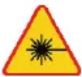
WARNING
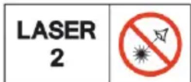
LASER RADIATION DO NOT STARE INTO THE BEAM OF THE LASER DIODE
Wavelength 630-670 nm Max. output power <1 mW Class 2 laser product
3 Functional description
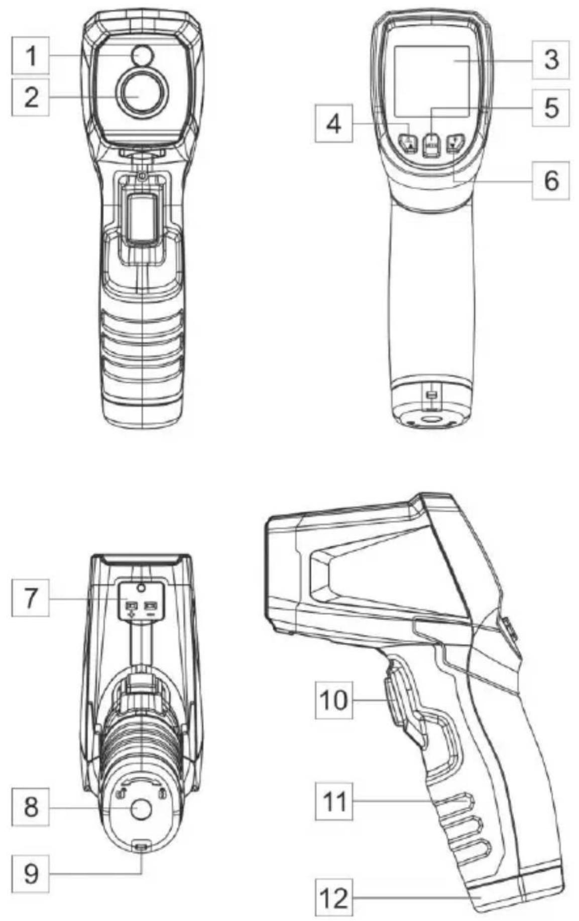
3.1 Device description
1 Laser
2 Infrared sensor
3 Display
4 Button ▲ / laser
5 MODE button
6 Button ▼ / display backlight
7 DIT-200 K-type probe input
8 Tripod socket
9 Lanyard hole
10 Measurement Trigger
11 Handle grip
12 Battery cover
3.2 Display
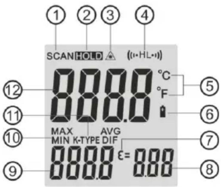
① Measuring indication
② Data hold
③ Laser "on" symbol
④ High alarm (HAL) and low alarm (LAL) symbols
⑤ Measurement unit
⑥ Low battery symbol
⑦ Emissivity symbol (ε)
⑧ Emissivity value
⑨ Temperature value: maximum, minimum, average, differential, from K-type probe (MAX, MIN, AVG, DIF, K-TYPE)
⑩ Temperature symbols: maximum, minimum, average, differential (MAX, MIN, AVG, DIF)
⑪ K-type probe symbol
⑫ Current temperature value
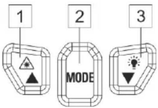
3.3 Buttons
1 Button ▲ / laser Setting ε, HAL, LAL.
2 MODE button
3 Button ▼ / display backlight Setting ε, HAL, LAL.
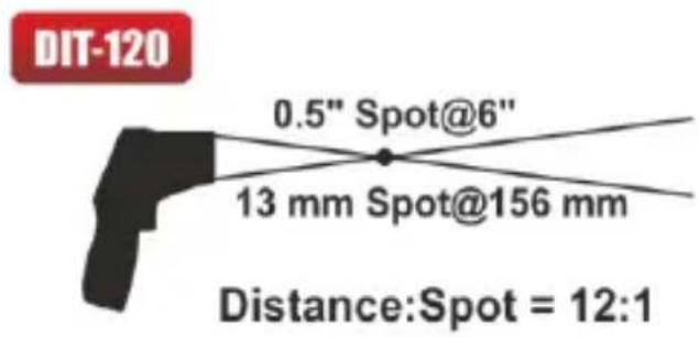
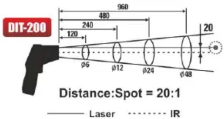
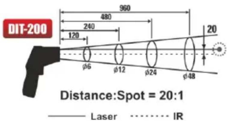
3.4 Distance and spot size
As the distance (D) from the object increases, the spot size (S) of the area measured by the unit becomes larger. The relationship between distance and spot size for each unit is listed below.
other
| Dimension | Value | | --------- | ----- | | Diameter | 960 | | Width | 480 | | Height | 240 | | Distance | 20 | | Laser | φ6 | | IR | φ12 | | Radius | 120 | | Thickness | φ24 | | Thickness | φ48 |4 Measurements
- Hold the meter by its handle grip and point it toward the surface to be measured.
- Pull and hold the trigger to turn the meter on and begin testing. The display will light if the battery is good. Replace the battery if the display does not light.
- Release the trigger and the HOLD display icon will appear on the LCD indicating that the reading is being held.
- The meter will automatically power down after approximately 10 seconds after the trigger is released.

- Holding the meter by its handle, point the IR Sensor toward the object whose temperature is to be measured.
The meter automatically compensates for temperature deviations from ambient temperature. Keep in mind that it will take up to 30 minutes to adjust to wide ambient temperatures are to be measured followed by high temperature measurements. - Some time (several minutes) is required after the low (and before the high) temperature measurements are made. This is a result of the cooling process, which must take place for the IR sensor.
5 Functional design
5.1 Functionality
- In the measuring time, pressing MODE keys to display MAX value, MIN value, DIF value or AVG.
- In the measuring time, if the Type K thermocouple is not connected, you can adjust emissivity by pressing ▲▼ buttons.
- In the HOLD mode, you can adjust °C/°F unit by pressing ▲▼ buttons.
• You can turn on/off the laser by pressing ▲ button at any state. - You can turn on/off the LCD backlight by pressing ▼ button at any state.
- To set values for the high alarm (HAL), low alarm (LAL) and emissivity ( ), press the MODE button until the appropriate code appears in the display, press the ▲▼ buttons to adjust the desired values.
5.2 Functions of MODE button
In the HOLD mode, press the MODE button also allows you to access the set state:
• MAX, MIN, DIF, AVG or LOG display,
- emissivity () ,
• high alarm (HAL) on/off,
- HAL adjustment,
- low alarm (LAL) on/off,
- LAL adjustment,
• °C/°F.
Each time you press MODE you advance through the mode cycle. The activity of a selected parameter is signaled by a blinking symbol on the display. The diagram shows the sequence of functions in the mode cycle.
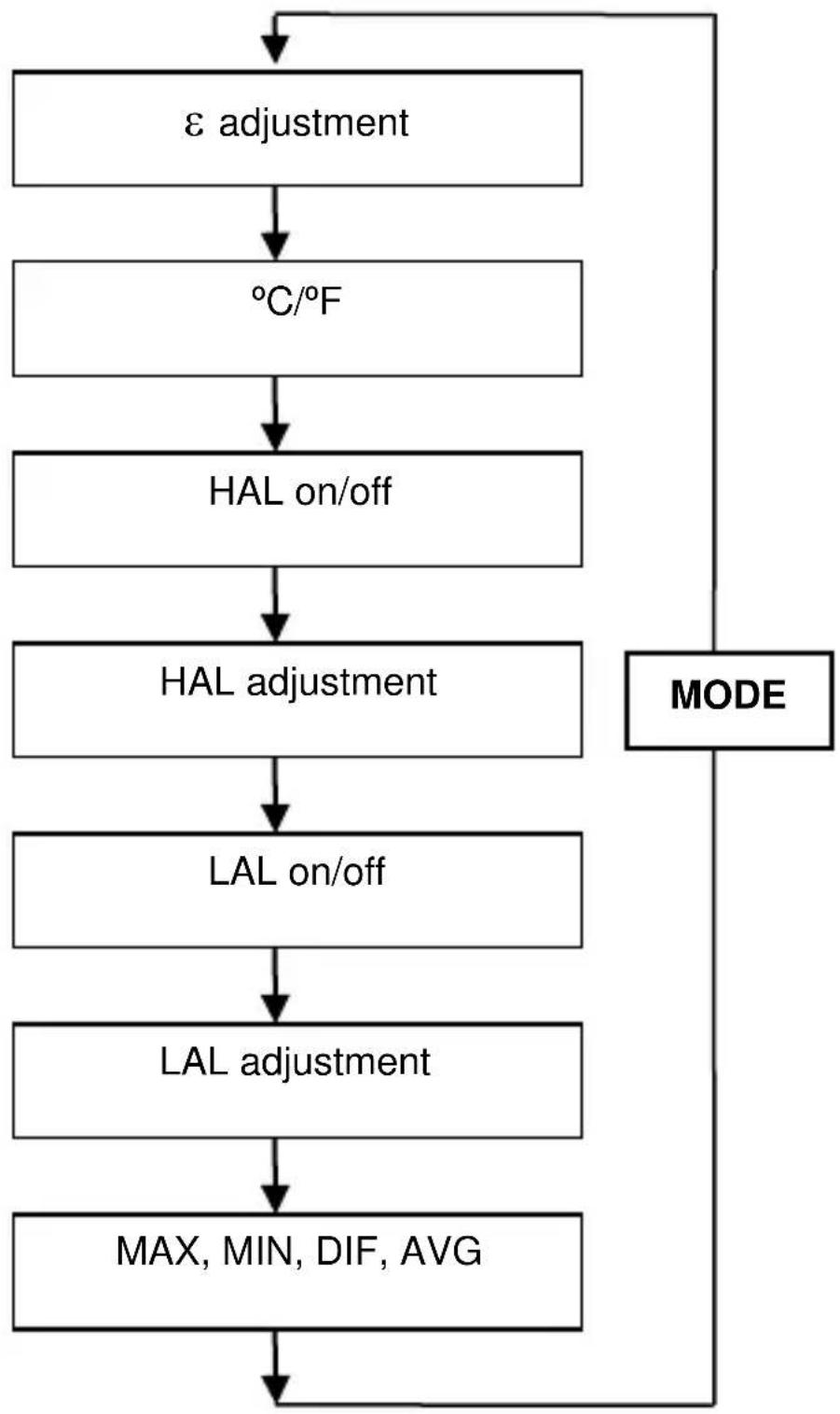
flowchart
graph TD
    A["ε adjustment"] --> B["°C/°F"]
    B --> C["HAL on/off"]
    C --> D["HAL adjustment"]
    D --> E["LAL on/off"]
    E --> F["LAL adjustment"]
    F --> G["MAX, MIN, DIF, AVG"]
    G --> H["MODE"]
Fig. 1. Sequence of MODE button
5.2.1 Emissivity ( ) adjustment
The emissivity ( ) digitally adjustable from 0,10 to 1,0 by pressing ▲▼ buttons.
5.2.2 °C/°F
Pressing ▲▼ buttons to change the temperature unit (°C or °F).
5.2.3 High alarm (HAL) on/off
Turn on or off high alarm by pressing ▲▼ buttons.
5.2.4 HAL adjustment
Adjust high alarm value by pressing ▲▼buttons.
5.2.5 Low alarm (LAL) on/off
Turn on or off low alarm by pressing ▲▼ buttons.
5.2.6 LAL adjustment
Adjust low alarm value by pressing ▲▼ buttons.
5.2.7 MAX, MIN, DIF, AVG display
MAX (maximum) - maximum value of measurement.
MIN (minimum) - minimum value of measurement.
DIF (difference) - difference value of measurement.
AVG (average) - average value of measurement.
Adjustable display by pressing ▲▼ buttons.
6 Battery replacement
As battery power is not sufficient, battery replacement is required.
symbol displays. It means that

NOTE!
When making measurements with a battery's symbol on, one must take into account additional indefinite measurement uncertainty or unstable working of the meter.
Remove battery cover screw, open battery cover, then take out the batteries from instrument and replace them with 2 new AAA 1.5 V batteries. Place the battery cover back.
7 Cleaning and maintenance
- Repairs or service are not covered in this manual and should only be carried out by qualified trained technician.
- Periodically, wipe the body with a dry cloth. Do not use abrasives or solvents on this instrument.
- For service, use only manufacturer's specified parts.
- Clean the device with a cotton bud moistened with 70% alcohol.
8 Storage
In the case of storage of the device, the following recommendations must be observed:
- Make sure the meter and its accessories are dry.
- In the case the meter is to be stored for a prolonged period of time, the batteries must be removed from the device.
9 Dismantling and utilization
Worn-out electric and electronic equipment should be gathered selectively, i.e. it must not be placed with waste of another kind.
Worn-out electronic equipment should be sent to a collection point in accordance with the law of worn-out electric and electronic equipment.
Before the equipment is sent to a collection point, do not dismantle any elements.
Observe the local regulations concerning disposal of packages, worn-out batteries and accumulators.
10 Technical data
“m.v.” - measured value.
10.1 Temperature measurement range
10.1.1 IR temperature range
| Temperature range | D:S | Resolution |
| -50.0...650.0°C | 12:1 | 0.1°C |
| -58.0...999.9°F | 0.1°F | |
| 1000...1202°F | 1°F |
| Temperature range | Accuracy |
| -50...20°C | ±3.5°C |
| -58...68°F | ±6.3°F |
| 20...300°C | ±(1.0% m.v + 1°C) |
| 68...572°F | ±(1.0% m.v + 1.8°F) |
| 300...650°C | ±1.5% m.v. |
| 572...1202°F |
Operating temperature of 23 to 25°C (73 to 77°F)
10.1.2 IR temperature range
| Temperature range | D:S | Resolution |
| -50.0...999.9°C-58.0...999.9°F | 20:1 | 0.1°C0.1°F |
| 1000°C1000...1832°F | 1°C1°F |
| Temperature range | Accuracy |
| -50...20°C | ±3.5°C |
| -58...68°F | ±6.3°F |
| 20...300°C | ±(1.0% m.v. + 1°C) |
| 68...572°F | ±(1.0% m.v. + 1.8°F) |
| 300...1000°C | ±1.5% m.v. |
| 572...1832°F |
Operating temperature of 23 to 25°C (73 to 77°F)
10.1.3 Type K temperature range
| Temperature range | Resolution |
| -50.0...999.9°C | 0.1°C |
| -58.0...999.9°F | 0.1°F |
| 1000...1370°C | 1°C |
| 1000...2498°F | 1°F |
| Temperature range | Accuracy |
| -50...0°C | ±2°C |
| -58...32°F | ±3.6°F |
| 0...1370°C | ±(0.5% m.v. + 1.5°C) |
| 320...2498°F | ±(0.5% m.v. + 3°F) |
10.2 Other technical data
a) response time.... 150 ms
b) spectral response....8...14 μm
c) emissivity.....digitally adjustable from 0.10 to 1.00
d) over range indication......LCD will show “----”
e) polarity....automatic, (-) sign for negative polarity
f) diode laser:
g) operating temperature 0 to 50°C (32 to 122°F)
h) storage temperature....-10 to 60°C (14 to 140°F)
i) operating humidity....10% to 90%,
j) storage humidity ....<80%
k) power supply 2x AAA 1.5 V battery
I) safety......CE" Comply with EMC
m) weight:
- DIT-120 231 g
- DIT-200 242 g
n) dimensions
- DIT-120 170 x 50 x 85 mm
- DIT-200 170 x 50 x 95 mm
11 Manufacturer
The provider of guarantee and post-guarantee services is:
SONEL S.A.
Wokulskiego 11
58-100 Świdnica
Poland
tel. +48 74 884 10 53 (Customer Service)
e-mail: customerservice@sonel.com
web page: www.sonel.com

MANUAL DE USO
PIRÓMETRO
TERMÓMETRO PROFESIONAL POR INFRARROJOS SIN CONTACTO
DIT-120 • DIT-200

other
| Dimension | Value | | --------- | ----- | | Diameter | 960 | | Distance | 20 | | Width | 480 | | Height | 240 | | Radius | 120 | | Object | DIT-200 (laser) | | Object | IR (diameter) | | Object | Spots (dot size) | | Object | Spot (spot) | | Object | 20:1 (distance) |4 Mediciones
other
| Dimension | Value | | --------- | ----- | | Diameter | 960 | | Width | 480 | | Height | 240 | | Distance | 20:1 | | Diameter | 120 | | Width | 6 | | Diameter | 24 | | Width | 48 |4 Messungen
- INSTRUKCJA OBSŁUGI 1
- USER MANUAL 18
- MANUAL DE USO 35
- CONTENTS
- Introduction
- WARNING
- Safety
- LASER RADIATION DO NOT STARE INTO THE BEAM OF THE LASER DIODE
- Functional description
- Device description
- Display
- Buttons
- Distance and spot size
- Measurements
- Functional design
- Functionality
- Functions of MODE button
- Emissivity ( ) adjustment
- °C/°F
- High alarm (HAL) on/off
- HAL adjustment
- Low alarm (LAL) on/off
- LAL adjustment
- MAX, MIN, DIF, AVG display
- Battery replacement
- NOTE!
- Cleaning and maintenance
- Storage
- Dismantling and utilization
- Technical data
- Temperature measurement range
- IR temperature range
- Type K temperature range
- Other technical data
- Manufacturer
- MANUAL DE USO
- PIRÓMETRO
- TERMÓMETRO PROFESIONAL POR INFRARROJOS SIN CONTACTO
- Mediciones
- Messungen
Brand : Sonel
Model : DIT-120
Category : Measurement