UV-260 - Measurement Sonel - Free user manual and instructions
Find the device manual for free UV-260 Sonel in PDF.


| Product Type | UV Radiometer (UV-A/UV-B Meter) |
| Brand | Sonel |
| Model | UV-260 |
| Measurement Range | 0 to 20 mW/cm² (UV-A) / 0 to 10 mW/cm² (UV-B) |
| Accuracy | ±5% of reading ±2 digits |
| Resolution | 0.01 mW/cm² |
| Detector Type | Silicon photodiode with UV filter |
| Display | Backlit LCD, 4-digit |
| Power Supply | 9V alkaline battery (6F22) or rechargeable battery |
| Battery Life | Approximately 100 hours continuous use |
| Dimensions | 150 x 70 x 30 mm |
| Weight | 200 g (including battery) |
| Main Functions | UV intensity measurement, data hold, max/min recording, auto power off, low battery indication |
| Data Output | USB interface (optional) |
| Operating Temperature | 0°C to 50°C |
| Storage Temperature | -20°C to 60°C |
| Humidity | ≤80% RH non-condensing |
| Standards Compliance | EN 14255, ISO 17166 |
| Accessories Included | Carrying case, battery, user manual, calibration certificate |
| Maintenance | Clean housing with dry cloth; keep sensor lens clean using lens tissue |
| Safety Precautions | Do not expose sensor to intense UV sources without diffuser; avoid eye exposure to UV |
| Spare Parts & Repairability | Replaceable battery; for sensor repair contact Sonel service center |
| General Information | Designed for professional UV measurement in industrial, laboratory, and field applications |
Frequently Asked Questions - UV-260 Sonel
User questions about UV-260 Sonel
0 question about this device. Answer the ones you know or ask your own.
Ask a new question about this device
Download the instructions for your Measurement in PDF format for free! Find your manual UV-260 - Sonel and take your electronic device back in hand. On this page are published all the documents necessary for the use of your device. UV-260 by Sonel.
USER MANUAL UV-260 Sonel
USER MANUAL
CORONA CAMERA
UV-260
USER MANUAL
CORONA CAMERA UV-260

SONEL S.A.
Wokulskiego 11
58-100 Świdnica
Poland
Version 1.06 03.07.2023
The UV-260 Corona Camera detects and precisely locates corona discharge emanating from high-voltage devices. It will help locate and determine the power of a discharge by capturing UV radiation released during corona discharge and provides a reliable method for the technical assessment of the operation and behaviour of high-voltage equipment.
When corona discharges are detected, the camera will overlay images of the corona on the visible image. Images are displayed in real time on the camera's screen. Under user control the images may be also recorded as a video file. Images may be stopped and saved as a still image. Recorded images and videos are stored on a removable SD card in a format compatible with viewing on personal computers.
Main features of UV-260:
• high UV-sensitivity, user adjustable
• automatic or manual focus adjustment for real image and UV image
• combining of visible-spectrum images and UV-spectrum images
• automatic reduction of noise and interference
- 5.7" TFT touch-screen
- designed to operate in sunlight
• UV discharge detection alarm
• built-in GPS system for recording location
- precisely locates UV discharge sources
- UV discharges and visible images recorded as photos or videos in common PC format report generator program included
CONTENTS
- Introduction......5
- Safety 5
- The principle of the operation 6
3.1. Electromagnetic radiation: visible, infra-red, ultraviolet 6
3.2. Mechanism of corona discharge 7
3.3. Why corona discharge? 8
3.4. Detection of corona discharge 8
- Preparing the camera for operation....10
4.1. External design of the camera 10
4.2. Mounting on a tripod....11
4.3. Moving the camera 12
- Ports and buttons....13
5.1. External ports....13
5.2. Layout and functions of buttons....14
5.2.1. Navigation buttons.... 14
5.2.2. Operating mode buttons 15
5.2.3. Control of power supply / charging and alarm - corona discharge indicator.... 15
- Operation and battery charging 16
6.1. Inserting the battery 16
6.2. Charging the battery 16
6.3. Guidelines for using the battery 16
- Working with UV-260 camera 17
7.1. Operation of the buttons 18
7.1.1. Recording a video.... 18
7.1.2. Recording a static image 18
7.1.3. Switching the image mode.... 18
7.1.4. "Freezing" displayed image 18
7.1.5. Changing the focus mode.... 18
7.1.6. Gain adjustment 18
7.1.7. Zoom.... 19
7.1.8. Manual focus.... 19
7.1.9. Zooming in 19
7.1.10. Playing a voice note 19
7.1.11. Zooming UV+ image 19
7.2. Operating the menu 20
7.2.1. Main menu 20
7.2.2. Image Settings 21
7.2.3. Video 22
7.2.4. Image 22
7.2.5. System 22
7.2.6. Sub-menu "System Settings" 23
- "Sonel UV Analyse" software....24
8.1. System requirements....24
8.2. Software operation....24
8.2.1. Starting-up software 24
8.3. Interface 25
8.3.1. Main function area 25
8.3.2. Toolbar 26
8.3.3. Template selection 27
8.3.4. Appearance setting & font setting....28
8.3.5. Cancel 28
8.3.6. Line 28
8.3.7. Edit box 28
8.3.8. Add pictures 29
8.3.9. Image setup.... 31
9.1. Cleaning and maintenance 39
9.2. Storage 39
9.3. Dismantling and disposal 39
9.4. Transport....39
10. Technical specifications .... 40
11. Manufacturer 41
1. Introduction
Thank you for choosing the UV-260 corona camera. It is a high-quality imaging device that is easy and safe to use. Carefully read this manual before the first use to prevent errors and problems while operating the device.
This manual contains three types of warnings that describe the possible risks both for the user and the device. Information with a "WARNING" describe situations which may endanger the user's life or health when instructions are not followed. "CAUTION!" describes of a situation which may result in damage to the device when instructions are not followed. Indication of possible problems is preceded by "Note".
The device has been designed, developed, and manufactured in accordance with ISO 9001 quality systems. Sonel reserves the right to change device specifications without prior notice. Copyright of this manual and software are the property of SONEL S.A.
2. Safety
WARNING:
Do not attempt to open the device, as none of the components can be repaired or calibrated by the user. Any maintenance activities may be carried out only by authorized service personnel.
NOTE
Do not drop, or subject the camera to rough handling or shocks during operation, handling, and transportation.
NOTE
Avoid pointing the lens directly at the sun or objects that emit very high temperature as this may cause damage. Take care to observe this precaution and make sure the camera is not pointed at the sun when switching the device ON/OFF.
NOTE
Never touch the lens. Dust accumulated on the lens may be removed only by using special tools or compressed clean air.
The camera should be stored in cool, dry place, away from sources of strong electromagnetic fields. When the camera is not used for a long time, remove the batteries.
During operation the camera should be securely fastened to minimize shake and vibrations that will adversely affect the accuracy.
WARNING
Do not use the camera if it's enclosure is damaged in any way as this is a safety threat to the user.
When working with the device, observe the technical conditions specified in this manual.
Damage to the camera, resulting from improper use, alteration and obvious negligence are not covered by the warrantee.
3. The principle of the operation
Corona discharge is one of three types of partial discharge. Partial discharge is the breakdown of an insulator (or dielectric) caused by high voltage stress, usually in a portion or area between two conductors that does not result in a complete short circuit. In addition to corona discharge there are surface discharges, due to contaminated insulator surfaces, and internal discharges caused by the degradation of the insulation that results in voids or pockets that provides paths for partial discharge to develop.
These situations are progressive in that discharge currents exacerbate further degradation ultimately leading to complete insulator failure. Corona-type partial discharge is the localized ionization of a gaseous insulation system, such as air, usually confined to a limited distance between two conductors. Corona can occur within voids in insulators as well as at the surfaces where conductors and insulators meet.
3.1. Electromagnetic radiation: visible, infra-red, ultraviolet
Individual types of electromagnetic radiation have wavelengths as shown in Figure 1.
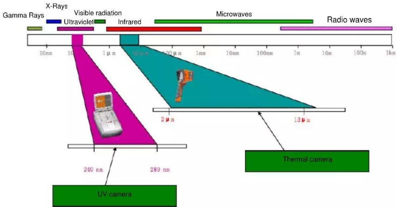
Figure 1: Electromagnetic waves of different lengths.
3.2. Mechanism of corona discharge
Corona discharge is a current flow, usually in a gas such as air, from a discharge electrode under high voltage conditions that causes ionization of the surrounding gas. Ionization is the separation of electrons from the gas atoms. If sufficiently ionized the gas can create a plasma; ionized matter containing electrically charged particles, around the electrode. The ions in the plasma create an electrical path that carry the electrons to lower potential.
If the discharge electrode has a sharp or pointed shape, a high-voltage potential gradient is generated around the point. If the potential gradient is high enough to cause ionization a discharge will occur. At very high voltage it may be a sparking phenomena, or it may be an arc whereby a plasma is created that establishes a path of continuous electron flow. Corona accompanies plasma states but also occurs when ionization levels are not at a full plasma state of high volume electron flow; i.e. corona emissions can also be initiated a lower level of discharge or electron flow provided ionization is present.
Most corona discharge is invisible in daylight. Even in total darkness it may be barely visible as a blue-violet afterglow as most of the radiation generated is in the ultraviolet range and invisible to human eye. Attempting to observe corona at night is virtually impossible since total darkness cannot be achieved in urban environments. Other methods of detection attempts to use acoustics to detect the crackling sounds that can accompany discharges but these methods are unreliable and cannot precisely locate the source of corona generation. Thus, acoustic-based detection methods are being replaced with UV-based detectors that are far more effective.
Corona discharges are generated in the electromagnetic spectrum wavelengths in the range between 200 to 405nm . Solar radiation contains visible light, infra-red, and ultraviolet radiation. By using an appropriate filter with wavelength between 240 to 280nm to suppress UV radiation from the sun the camera is designed to detect corona even in daylight conditions.
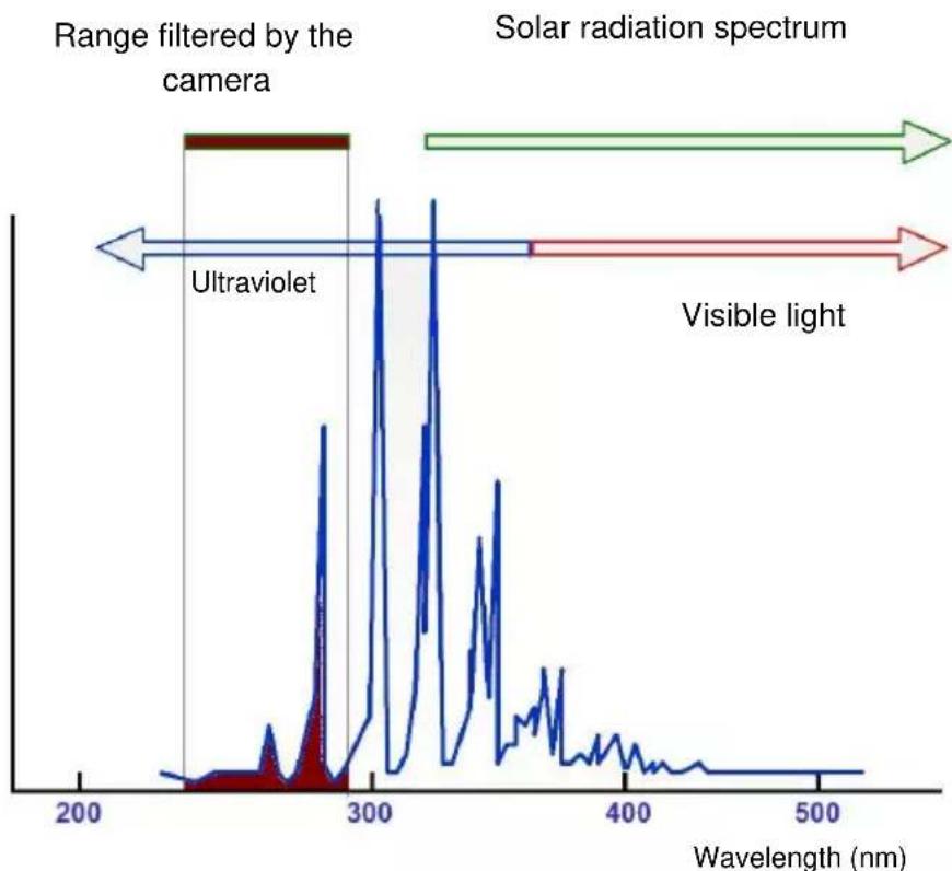
line
| Wavelength (nm) | Intensity | | --------------- | --------- | | 200 | Low | | 250 | Medium | | 300 | High | | 350 | Medium | | 400 | Low | | 450 | Very Low | | 500 | Very Low |Fig. 2: The spectrum of corona discharge
UV-260 - USER MANUAL
Depending on the polarity of the discharge electrode, the corona discharge may be positive or negative. In either case of negative or positive discharges photons are the main source of radiation. When the gas atoms are ionized their electrons are "excited" and kicked up to a higher energy states. Photons are released by the ionized atoms as they return to lower energy states. The corona camera shows a display scale in "UV photons" to provide an indication of the volume of photons generated.
Positive discharge is said to be homogeneous; the majority of charges are concentrated close to the electrode so the discharge area is well defined and easily located. Negative discharge at the same voltage may be weaker and more difficult to locate since the energy is more spread out over a wider area.
3.3. Why corona discharge?
Corona discharges are a loss of energy. Unwanted corona discharge also cause a variety of problems such as radio interference i.e. poor reception of radio signals due to noise coming from nearby high voltage power lines. The most adverse effect of corona discharges is the impact on the condition of insulation elements resulting in "wear and tear" over time; i.e. the gradual deterioration of the insulator and it's ability of the to provide a dielectric barrier. Even the presence of small discharges cause adverse effects. The discharge current flow generates corrosive substances that contribute to the breakdown of insulators creating voids and cracks. These enable the ingress of moisture to internal components, further accelerating degradation.
If left unchecked bad insulation can bring about the failure of entire power transmission systems. Since high voltage transmission systems are the main arteries of power that serve millions of consumers, any disruption to the electrical grid's transmission systems is both economically and socially disastrous. Therefore, it is prudent to detect the early stages of corona discharges to catch incipient problems before they develop and lead to permanent damage that results in costly repairs and wide-area blackouts. Locating corona discharges is a sensible cautionary preventative maintenance measure, similar to infra-red thermal camera inspection methods, to discover potential problems before they arise.
3.4. Detection of corona discharge
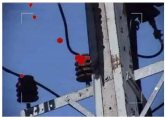
The UV-260 detects and locates corona discharges by detecting their UV radiation. The level of discharge is quantified and the number of discharges in a certain time-frame is represented graphically by the 'UV image'. The camera operates in both the visible light and the UV spectrums. By pointing the camera at a desired object and viewing it as a real image, in the same way as any video camera, any detected UV emissions are precisely overlaid on the visible image. The UV radiation is represented as a white, blue, or red video image rendered against the visible image. This provides an accurate method of locating the source of emissions and therefore the point of degradation that would otherwise be difficult to distinguish in high voltage transmission systems, or complex substations with multiple conductors and equipment. Inspection for corona with the UV-260 is inherently safe when high voltage systems are live since inspection is performed from a distance.
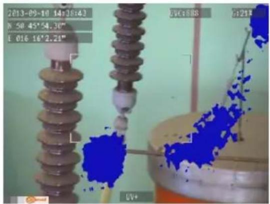
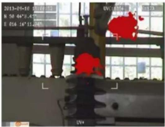
Fig. 3, 4. Corona discharge in laboratory conditions.
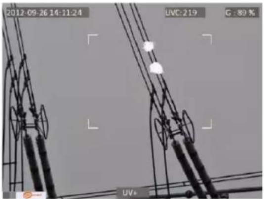
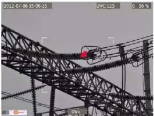
natural_image
Exterior view of a high-voltage transmission tower with visible insulators and wiring (no signage or text)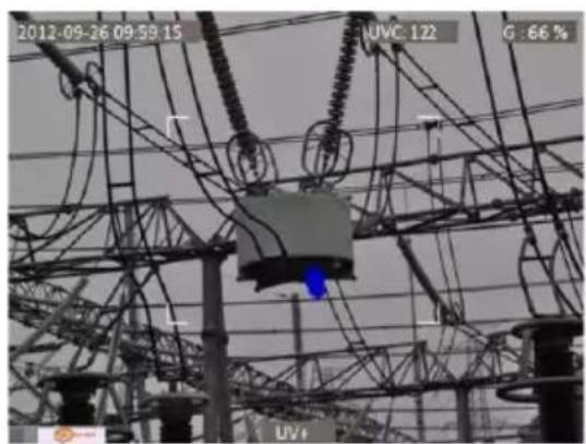
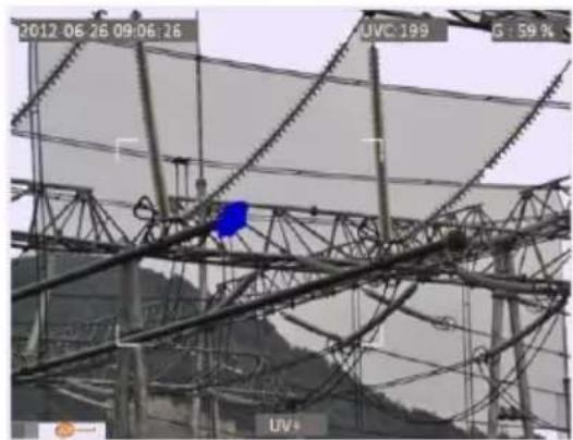
Fig. 5-8. Corona discharge in real power grids.
natural_image
Electrical substation with high-voltage insulators and wiring against a clear blue sky (no text or symbols visible)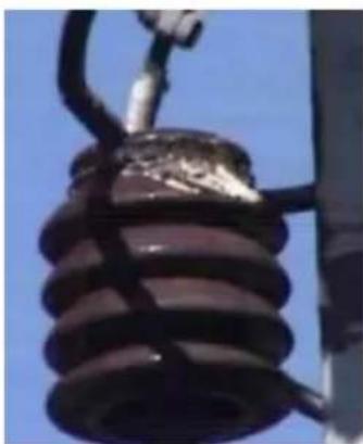
natural_image
Close-up of a damaged electrical insulator with visible wiring and mounting bracket against blue sky (no text or symbols)Fig. 9, 10. Corona discharge and its effects.
4. Preparing the camera for operation
4.1. External design of the camera
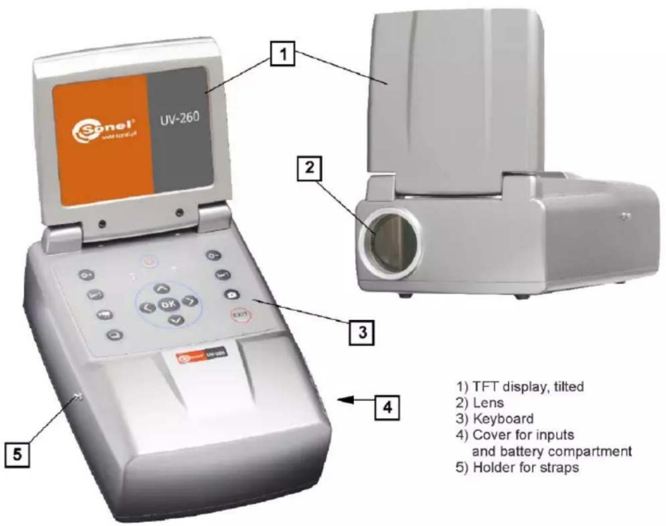
The UV-260 is compact, simple, and ergonomic camera to use. It may be operated on a tripod or used as a hand-held tool. Its features are illustrated in Figures 11 and 12.
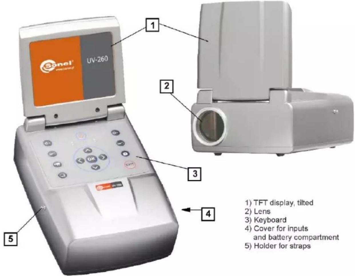
Fig. 11. Parts of Camera UV-260.
4.2. Mounting on a tripod
For long periods of observation mounting the camera on a tripod is recommended to eliminate shake and vibration (Fig. 12). A standard, threaded tripod mount is provided at the bottom of the camera.
Note. Firmly attach the camera to the tripod to prevent accidental damage.
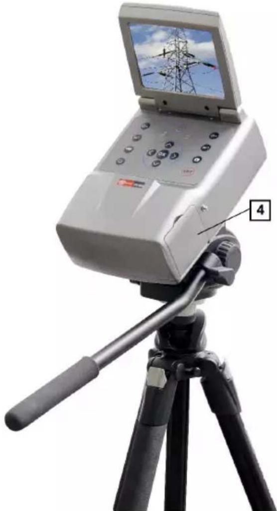
natural_image
Photograph of a handheld electronic device mounted on a tripod, displaying a screen with power lines and a labeled component (no text or symbols on the device itself)Fig. 12 UV-260 mounted on a tripod.
4.3. Moving the camera
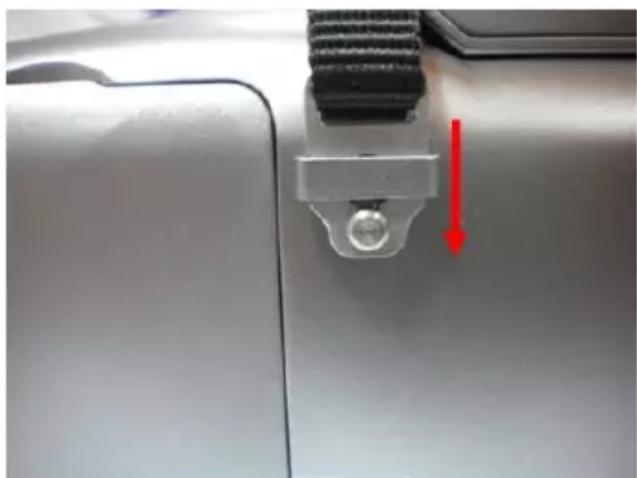
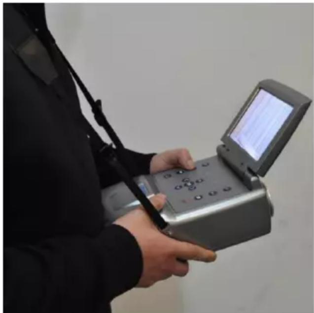
The UV-260 may be used as a hand-held device, or the operator can use the more convenient strap to ease fatigue from holding for long periods. The strap also frees the operator's hands during operation (Fig. 13, 14).
CAUTION!
To prevent dropping and damaging the camera when fastening and unfastening of the strap place the camera on a table or other surface, and fasten or unfasten the strap in the upright position (fig. 13). Test the strap is securely fastened before operation.
natural_image
Close-up of a metallic vehicle door panel with a red arrow pointing to a button detail (no text or symbols visible)Fig. 13. Fixing strap to the holders.
The camera when suspended on the strap allows the operator to easily use the keyboard (Figure 14).
natural_image
Person holding a handheld electronic device with a screen displaying text (no visible text or symbols on device)Fig. 14. The camera mounted on the strap.
5. Ports and buttons
5.1. External ports
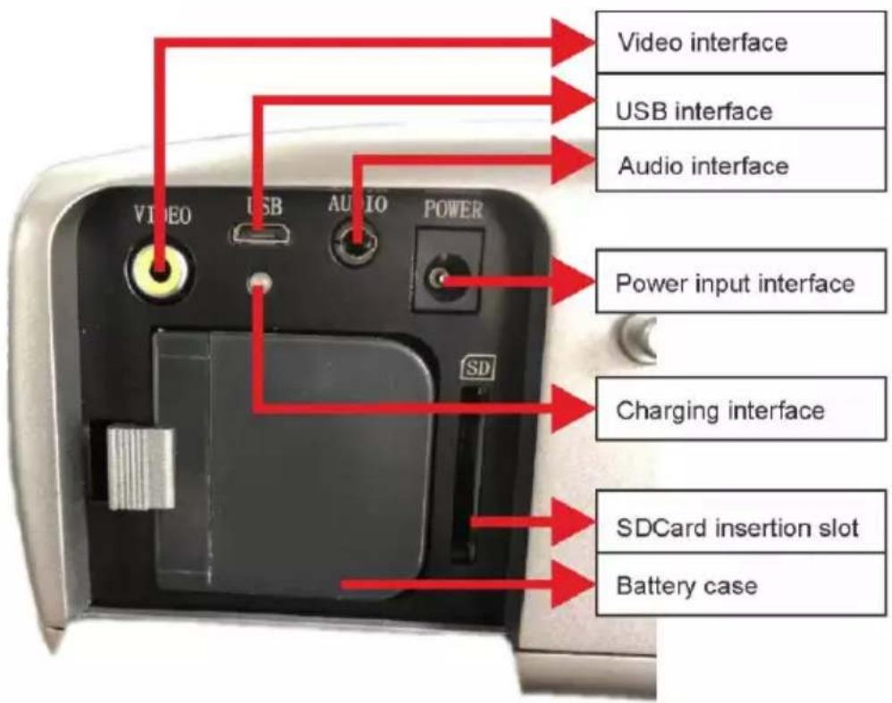
Camera interfaces, charging indicator, power adapter input, SD card slot, and the battery compartment are located under the cover on the side of the camera (Fig. 15).
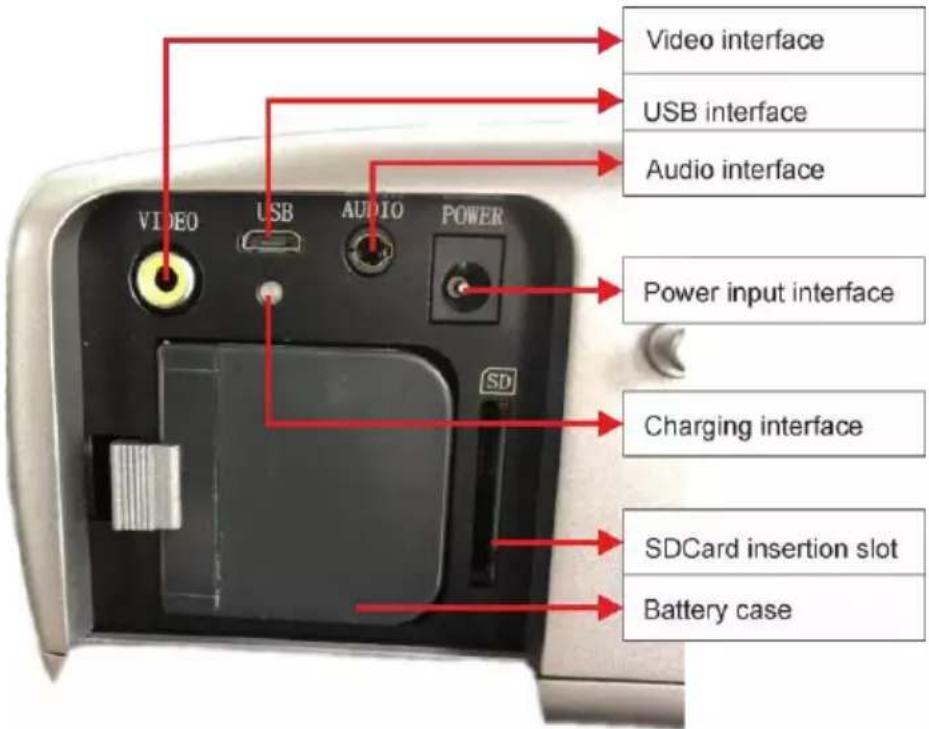
Fig. 15. Arrangement of ports under the cover.
Video output may operate in PAL or NTSC system.
The SD card must be formatted in FAT32.
When recording voice notes speak closely into the microphone. Plug the microphone headset into the audio input located under the cover.
CAUTION!
When inserting the battery, pay attention to the correct polarity.
Voltage connected to power input cannot exceed 12V.
5.2. Layout and functions of buttons
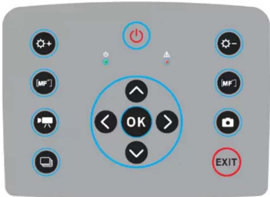
Fig. 16. Arrangement of the control panel buttons.
5.2.1. Navigation buttons
Buttons for menu operation and image functions:

- Up,
- Down,
- Left,
- Right,
- confirm,
- exit without confirmation.
In addition to menu navigation, functions of the buttons are as follows:
- "freezing" the displayed image,
- switching into the focus adjustment mode,
- playing a voice note
- zooming in combined (mixed) image mode (real image +UV).
5.2.2. Operating mode buttons
- image display mode switch, repeated pressing of the button causes toggling of the following modes: UV image only - visible image mode - mixed mode (UV plus visible image).


- saving the still image,
- video recording,
and - manual focus adjustment,
and - zoom in/out
5.2.3. Control of power supply / charging and alarm - corona discharge indicator

- switching on / off,
- power indicator,
- corona discharge indicator.
6. Operation and battery charging
The UV-260 is powered by a dedicated lithium-ion rechargeable battery, which should be charged only with the charger included with the camera. Any other batteries, even of the same shape, and other chargers may damage the camera and present a danger to the user.
The battery may be also charged by the camera via an AC adapter or a car adapter (12V) - both included with the camera.
When battery level is low a message will be displayed on the screen indicating the need for recharging.
6.1. Inserting the battery
Insert the battery into the battery compartment located under the cover for inputs and battery compartment (Fig. 15).
6.2. Charging the battery
The battery may be charged using the external charger or by connecting the AC adapter (the battery remains inside the camera) to the device using the input located slot under the battery compartment cover 4.
Charging in the external charger is indicated by red colour of charging indicator. Completed charging process is indicated by green colour of charging indicator.
Charging inside the camera is indicated by red colour of the indicator, its completion by green colour (Fig. 15).
Charging also takes place during operation of the camera.
WARNING.
At high temperatures do not turn on the camera while charging the battery, as it may decrease battery life, or even cause fire.
6.3. Guidelines for using the battery
Charge the batteries in a dry indoor location. Do not charge the batteries outside, especially during rain, etc.
WARNING.
Do not short-circuit the battery, and avoid accidental short circuits by preventing the battery terminals from coming into contact with other metal, or loose objects.
The battery should be stored at a temperature not exceeding 60^ C.
When charging is finished, disconnect the external power supply adapter from the mains.
When replacing the battery, with the camera connected to the power supply adapter, first connect the battery to the camera, and only then connect the AC adapter.
It is forbidden to use non-original batteries and chargers.
7. Working with UV-260 camera
In order to switch the camera on press and hold button for approx. 2 seconds. The camera starts by performing auto-tests for about 25 seconds, then it switches on the operating screen (Figure 17).
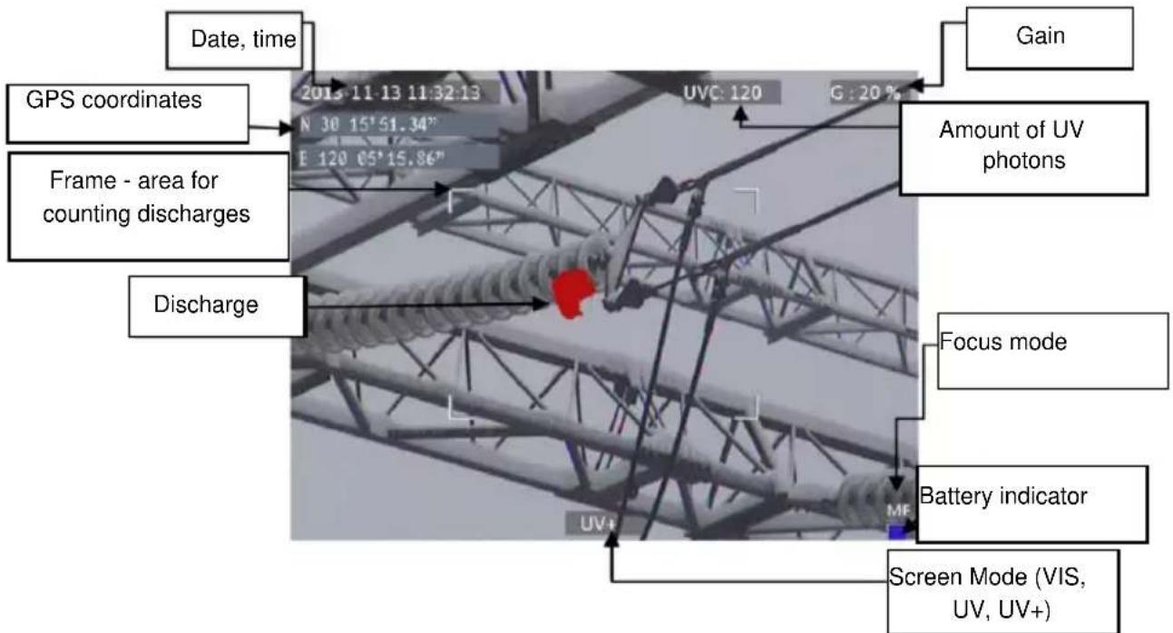
Fig. 17. Working screen in mixed image mode - detecting corona discharges.
The screen, in addition to the image in the selected mode (UV, visible, mixed), displays the following information:
- current date and time,
- GPS coordinates of the measurement location
- signal gain level
- battery charge status
- focus adjustment mode (auto or manual),
- image mode indicator: mixed UV+, visible image VIS, or UV image only: UV
The white frame is the effective area for photon counting, where discharges are recorded and the amount of UV photons indicated. The operator may select 3 frame sizes - large, medium, and small.
7.1. Operation of the buttons
Description of the operations available by pressing buttons in the working screen mode.
7.1.1. Recording a video
Press 📄 to start recording a video and saving it on a SD card. This allows real-time recording of images that are displayed on the screen. When recording video you may add a voice note using the headset connected the audio input. Video files are recorded in "avi" format that can be played in the camera or on a PC.
7.1.2. Recording a static image
Press to save the image displayed on the screen into the SD card.
When the image is recorded the screen displays the message "record a voice note". At this point you can record 20-second voice memo, press to start voice recording (with a microphone headset connected to the audio input). The image is saved and the camera returns to the real-time mode. Or press save the image without recording a voice note.
Note. For the best quality it is recommended to 'freeze' the image on the screen before saving it - see below.
7.1.3. Switching the image mode
Use 50ton to toggle and switch between the following modes: Visual image only VIS, UV discharge mode only (UV) and Mixed mode (UV+).
7.1.4. "Freezing" displayed image
Pressing < "freezes" the image allowing you to make a decision about saving it into memory. At this point:
- press to save image to the SD card and return to detection mode in real time;
- press again to return to the detection mode (real time) without saving the image.
7.1.5. Changing the focus mode
Press to change the focus mode from manual to automatic and vice versa. By default, the camera upon powering on is set to auto focus mode. In case of a complex image with many objects at different distances the focus may not be set automatically to the desired object. If so the operator can switch to the manual focus mode.
7.1.6. Gain adjustment
In UV image mode or in mixed mode (UV+) buttons and are used to increase or decrease the sensitivity of the camera UV detector. Increasing the sensitivity results in displaying both high and very low discharges, and may display unwanted UV interference. Decreasing the
sensitivity allows the operator to observe only high-power discharges, and more precisely locate their sources.
7.1.7. Zoom
In the visual image mode, use buttons and to zoom in/out the image by reducing or increasing the camera angle of view.
7.1.8. Manual focus
In manual focus mode (see 7.1.5), use buttons and to manually adjust the focus of the image.
7.1.9. Zooming in
In the image preview mode, press to zoom the image by 2x or 4x. When the image is enlarged, use buttons , , , to navigate through the image. Press to enter the real-time image mode.
7.1.10. Playing a voice note
When the image was saved with a voice note it may be played in the image preview mode by pressing. Use a headset connected to the audio input to listen to voice notes.
7.1.11. Zooming UV+ image
In Mixed image mode UV_+ and in UV mode UV, press to enlarge (zoom) the image by 1x or 2x. This makes it easier to precisely locate the source of UV emissions and the most probable location of physical damage or deterioration of the observed object by finding where the most UV emissions are originating from.
7.2. Operating the menu
The UV-260 does not display the menu on startup. Enter the main menu by pressing in OK the real-time image mode or by touching any place on the touch-screen. Press o such the screen where the menu is not displayed to close the menu.
Note. Menu options are simple and intuitive. All operations in the menu are performed by touching the individual items on the screen in drop-down menu sections, or by navigating through the menu using the cursor keys.
7.2.1. Main menu
With any opened drop-down menu, select the desired option by touching where it is displayed, or move the highlighted area in the menu with cursor keys on, then confirm the selection by pressing . At any stage you may press to the menu.
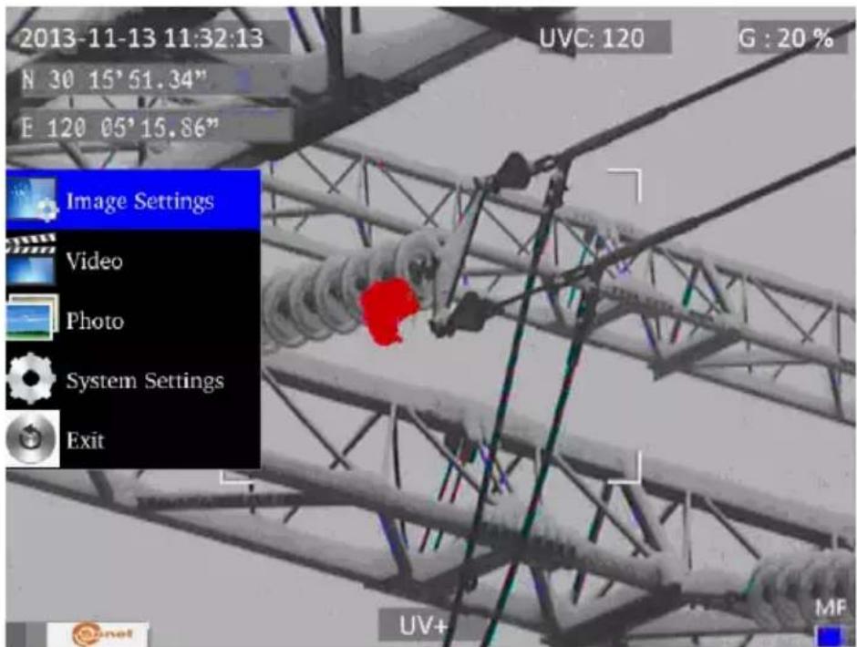
Fig. 18. Main menu.
7.2.2. Image Settings
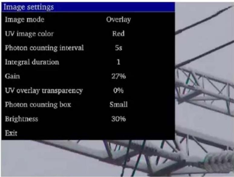
Fig. 19. Menu - Image Settings.
The "Image Settings" menu allows you to alter how UV images are displayed. Specific options are presented below. Select/change options in the same way as in the main menu (use "arrow" key and confirm by pressing , exit to the previous menu by ; or touch selected area of the screen).
Image mode: function is analogous to pressing button, select between Visible image, UV image and Mixed image.
UV Image color: select colour for displaying UV discharges (available colours: red, white and blue).
Photon counting interval: Set the interval time for photon counting, There are 10 time intervals of 1s, 2s, 3s, 4s, 5s, 6s, 7s, 8s, 9s, 10s.
Integral duration - integration time length: Set the integration duration, which can be set to 1, 2, 4, 8, 16 and 32. The integration function is used to accumulate the UV signal to filter out the random interference. Within the selected integration time, the discharge point appears repeatedly in the same place and is accumulated into larger signal, while the random interference signal will not be accumulated into a large signal, when the gain is reduced, the random interference will be filtered.
Gain: adjusts the sensitivity of UV detector (similarly - use buttons and in UV image mode UV or mixed mode UV+) to increase or decrease.
Note. Setting high gain allows you to capture weak UV signals and detect very small discharges, but it should be remembered that high gain may affect the accuracy of locating discharge sources. This is because as the UV image will cover a larger area of the visible image making it difficult to determine the exact location. All UV radiation from both the actual discharge source, as well as unwanted, interfering sources will be detected. The unwanted detection usually appears scattered and in random positions.
A good technique is to first set a high gain level to roughly determine the discharge location, and then gradually reduce the gain to a level that will show the precise location of discharges.
For relatively large interferences extend the averaging time and simultaneously reduce the gain level to eliminate background noise and better pinpoint the sources of corona discharges.
UV overlay transparency: sets the transparency of UV image overlaid onto the real image (0% - opaque, 50% - translucent)
Photon counting box: selects the area where discharges are counted. The frame can be set in 3 sizes: large, medium, and small.
Brightness: sets the brightness level of the screen, depending on external conditions.
Exit: return to the main menu.
7.2.3. Video
Provides functions for video files saved on the SD card: i.e. view, delete files, and view detailed information about recorded video files. File names correspond to their dates of creation.
7.2.4. Image
For viewing or deleting images saved on the SD card. While viewing images the operator can zoom in and play a voice note if previously recorded. Image file names correspond to the dates of their creation. The images are displayed in the form of a list or thumbnails.
7.2.5. System
After selecting "System" option a sub-menu is displayed where the user may change system settings to change:
- time settings
- factory settings
- formatting the SD card
- displaying information about the SD card
- displaying information about the camera
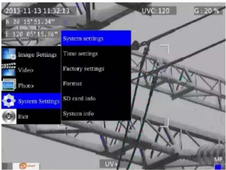
Fig. 20. System menu.
7.2.6. Sub-menu "System Settings"
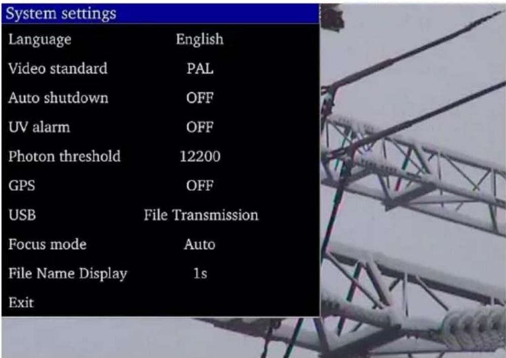
Fig. 21. "System Settings" Menu.
Language: selects the interface language.
Monitor: selects the video standard (PAL or NTSC) for the camera display screen.
Auto shutdown: sets the camera to automatically turn-off when no button is pressed for a set time.
UV alarm: turns the audible alarm, after detecting UV discharges, On or Off.
Photon threshold: sets the level of corona discharge (the amount of recorded photons) to trigger the alarm.
GPS: Turn GPS function on or off.
USB: There are two modes: video and file transmission.
① Video: Video needs to be used with Report software. In the device system settings, select video in USB. After the device is connected to the computer, open the video management button installed in theReport software on the computer, click the search button, search the device and then play it.
② File transmission: Select file transfer. After the device is connected to the computer, a removable storage device will appear on the computer. Double click to open it and select the required file or picture.
Focus mode: selects manual or auto focus (the same as pressing button).
File name display: Set the display duration of file namefrom available: 1s, 2s, 3s, 4s, 5s.
8. "Sonel UV Analyse" software
8.1. System requirements
Due to the large size of video files, you must provide enough disk space on your computer and meet the following requirements:
- CPU 2.0GHz processor or faster;
- 2Gbytes or more system memory;
- 80G or bigger hard disk;
- 1440×900 or higher resolution screen (Suggestion).
The software runs under Microsoft Windows 2000, XP, Vista and Windows 7.
8.2. Software operation
8.2.1. Starting-up software
After unzipping the software, click the software icon to open the software as shown in figure 22.
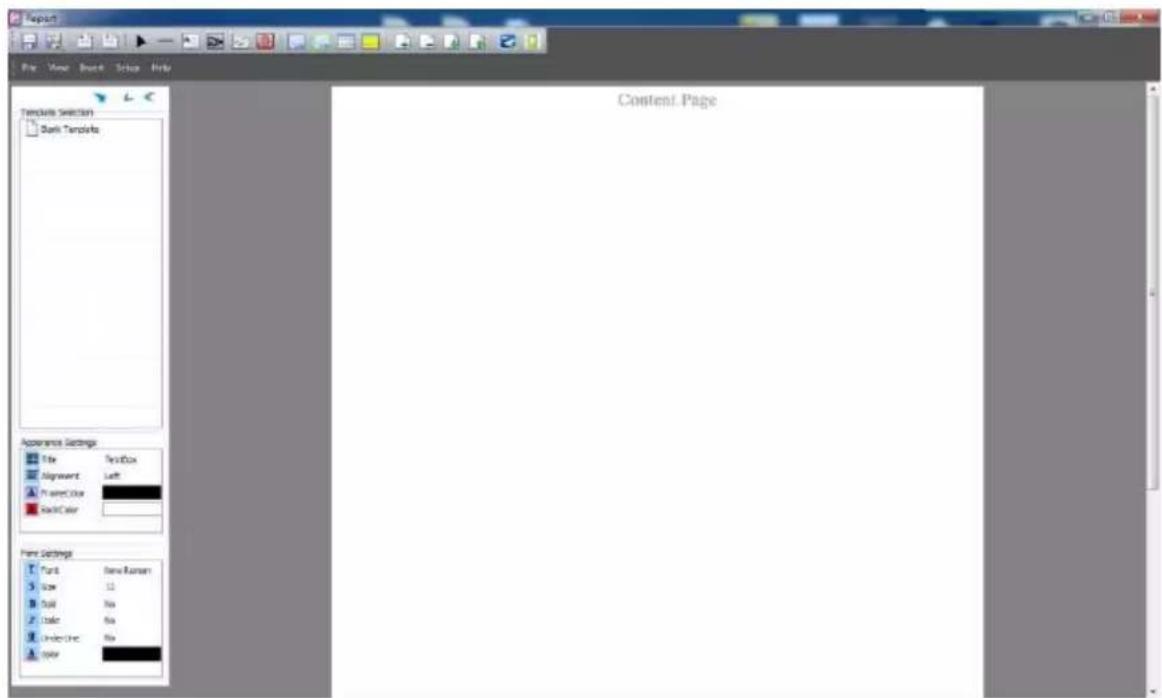
Figure 22
There will be a hint reminding users to download templates. After adding, users can also delete the template when you right-click the template name and select "Delete Template".
8.3. Interface
8.3.1. Main function area
There are five main functions in this area: File, View, Insert, Setup and Help.

Figure 23
a. File
It can save file as template or save template directly. And it can output words, manage files and videos, as well as batch export gray images.
Batch export gray images: Firstly, users have to click "File→Batch export gray image analysis". Secondly, select the templates and documents you need. And then click "output Word" to export gray images. If there are some documents that users don't need, you can click the "Delete" to delete them. As shown in the figure 24.
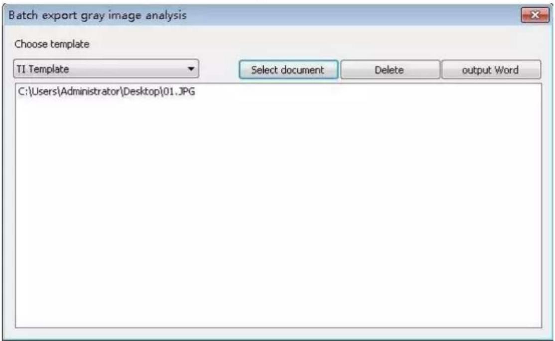
Figure 24
b. View
In this part, there is "Toolbar and Window" which can show or hide the toolbar and the status bar. As shown in the figure 25.
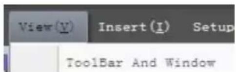
Figure 25
c. Insert
In this part, users can add the lines, edit boxes, original pictures, line analyses, picture boxes, LOGOs, list boxes and vertical lists. Besides, users can add or delete pages, as well as flip pages.
d. Setup
In this part, users can set up the temperature and add grid.
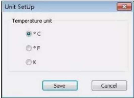
Figure 26
e. Help
In this part, users can look through the user manual of software when you click the "Doc"; get the information of the version when you click the "About"; and change the language when users click the "Language".
8.3.2. Toolbar
It includes all tools to edit report. Users can use the tools according to needs.

Figure 27
8.3.3. Template selection
When users edit the report, there are several kinds of templates you can choose, blank
template, IR template, UV template, and Gas template. Click to load template you need.
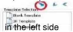
a. Blank template
When you choose the blank template, the edit area is blank and users can add things you needed.
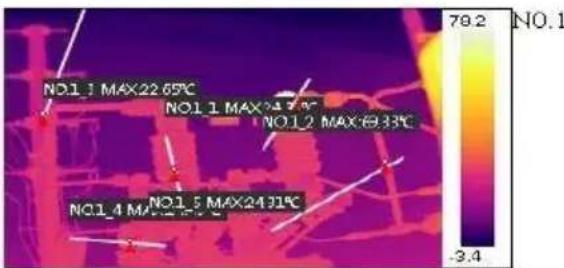
b. IR template
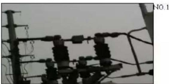
This template is compatible with the first-hand pictures shot by IR devices. Users can download templates by themselves. The edit area is setup already in order to save your time, but users can still add or delete things.
Infrared Detect Report
| Transformer Substation | XXX | Weather | XXX |
| Device Name ,Position | XXX | Device History Max Current(A) | 1540 |
| Rating Current(A) | 3150 | Load Current(A) | 1435 |
| GPS N | GPS E |
IR Image
Visible Image
| Pic Info | Data | NO.1 |
| Create Date | 2015-09-19 | |
| Create Time | 18:30:54 | |
| MessageObject | Data | |
| IO.1_1MaxTemp | 24.31°C | |
| IO.1_2MaxTemp | 69.33°C | |
| IO.1_3MaxTemp | 22.65°C | |
| IO.1_4MaxTemp | 24.43°C | |
| IO.1_5MaxTemp | 24.31°C |
natural_image
Electrical substation with insulators and power lines (no visible text or symbols)Figure 28
c. UV template
This template is compatible with the first-hand pictures shot by UV devices, which called UV template.
In UV template, users could look through the picture information of pictures which are shot by UV device, such as photon number, GPS, create time and so on. And users could make some records below in the template.
The edit area is setup already in order to save your time, but users can still add or delete things.
d. Gas template
This template is compatible with the first-hand pictures shot in gas mode.
8.3.4. Appearance setting & font setting
This area is the shown area by default. If users want to hide it, you have to click the left button of . According to your needs, you can set up the way of alignment, frame color and back color when you select a picture, a text box, a list box or a vertical list. Besides, you can set up the front, such as size, bold, colour and so on. As shown in figure 29.
Click to hide all the menu bars on the left, including template selection, appearance settings and font settings.
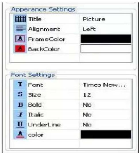
Figure 29
8.3.5. Cancel
When you click the tool in the toolbar unintentionally, users can click "Cancel" to cancel operation.
8.3.6. Line
Click "Line" if users want add horizontal lines, vertical lines or black boxes.
8.3.7. Edit box
Users can add edit boxes to take down notes.
8.3.8. Add pictures
a. Original picture
Select "Original Picture" in the toolbar, and then add the picture box to the ideal position, as shown in figure 30 and 31. (The box in figure 30 is unchecked so that it can't add picture. You need to select it with your left mouse button clicking, so that you can add a picture, as shown in figure 31.)
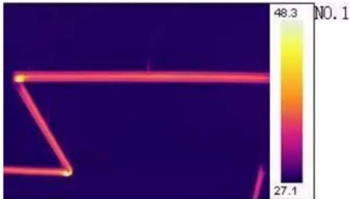
Select "File Manage" in the toolbar. When the menu bar appears, please double click the left mouse button to add pictures, as shown in figure 32. (Take the thermal image as example.)
Attention: The pictures in this part should be the first-hand pictures shot by IR or UV device, not including the visible images.
For images shot by IR device, users can set up the image attributes and play audios as clicking the right mouse button. For images shot by UV device, users can set up the image attributes as well. But the audio play function is not available for UV images. See also sec. 8.3.9 and 8.3.10.
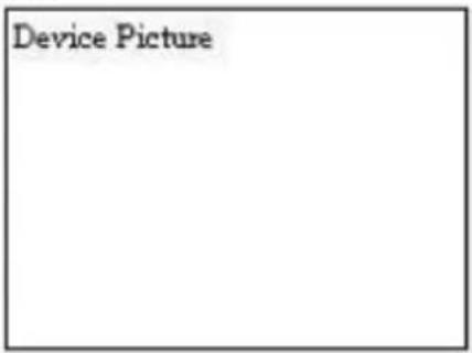
Figure 30
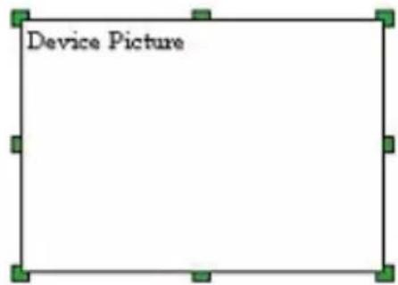
Figure 31
heatmap
| Value | | ------ | | 48.3 | | 27.1 |Figure 32
b. Picture box
This function is compatible with the "Original Picture". This function works only if there is a picture in the original picture box. By default, the box will show the visible picture of NO.1 original picture. Users can set up the property, original object number and device number in the menu bar, as shown in figure 33.
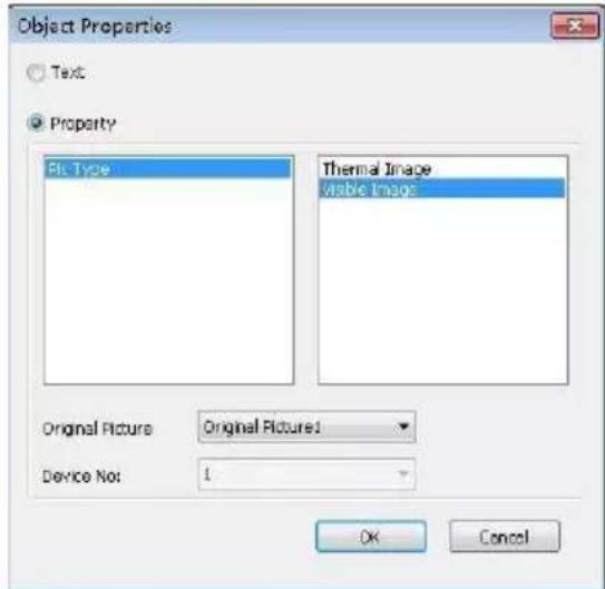
Figure 33
c. Logo
Select "LOGO" in the toolbar, and then add the picture box to the ideal position. Click the right mouse button and select
"Change LOGO" to add picture. In this function, any JPG/JPEG files could be added.
d. UltraMax picture
It is not available for the device without ultramax function.
Please turn on the UltraMax of device and take pictures before using this function.
Select "Original Picture" in the toolbar, and then add the picture box to the ideal position. Click the right mouse button and select "File Manage" in the toolbar. When the menu bar pops up, please select the ultramax picture, click the right mouse button and select "Ultrapix Picture", as shown in figure 34.
In this function, the picture will be much more clearer and the temperature analysis will be much more accurate.
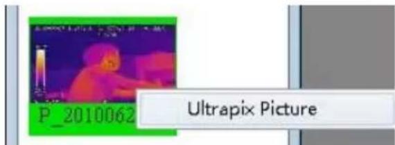
Figure 34
In Icon mode, the unchecked ultramax pictures are highlighted by yellow background, and the checked ultramax pictures are highlighted by blue background. In list mode, the ultramax pictures are distinguished by the mark \$
Click the right mouse button, and users can set up the attributes and temperature range, as well as play videos.
8.3.9. Image setup
a. IR non-gas image
After adding pictures, please click right mouse button and select "Attribute settings". The menu bar pops up, as shown in Picture 35.
a. The image setup is on the left, and the temperature range is on the right. Users can adjust the temperature range automatically or manually. In addition, users can add points, lines, regions, ellipse or polygon to the pictures, one at a time. And users can also delete one of them, delete all information, or initialize the adding operation. When adding polygon, click right button to finish drawing.
b. There are 12 color bars in total. And you can choose to show or hide temperature objects.
c. Users can set up the attributes of object, such as equipment materials, equipment distance, equipment name, max temperature and min temperature. And you can adjust the temperature range automatically or manually.
d. Please save the operation after setting, and then click "quit".
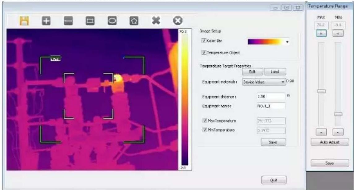
Figure 35
b. IR gas image
After adding pictures, please click right mouse button and select "Attribute settings". The menu bar pops up, as shown in Picture 36.
a. Switch the display between IR and Gas mode.
b. The operations of image attributes are the same as IR Non-gas Image.
c. UV images are not available for this function!
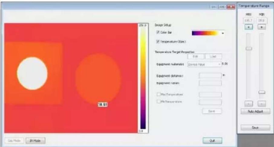
Figure 36
8.3.10. Audio play
Select the pictures you added by the function of original picture, and click right mouse button. Then select "Play Audio". The play interface will pop up automatically. However, this function is merely available for the pictures with voice annotations.
8.3.11. List box
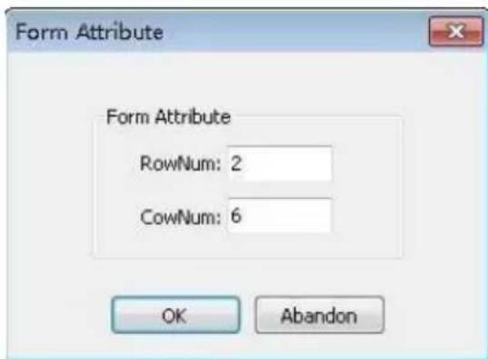
Figure 37
After addition, users can edit the table. For example, you can set up the appearance and font (refer to sec 8.3.4). However, cell merging is unavailable so that you have to splice tables by yourself. As shown in 38.
Select "List Box" in the tool bar, and add it into template. You can adjust row number and cow number upon you needs.
| Transformer Substation | XXX | Weather | XXX |
| Device Name Position | XXX | Device History Max Current(A) | 1540 |
| Rating Current(A) | 3150 | Load Current(A) | 1435 |
| GPS N | GPS E |
Figure 38
Users can change the display information when you select one certain cell, click right mouse button and select "Cell Properties". As shown in figure 39.
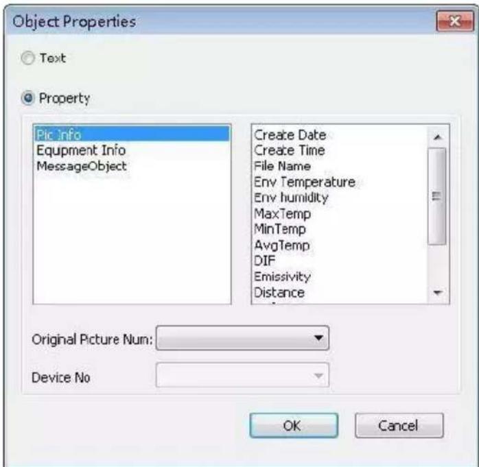
Figure 39
8.3.12. Vertical list
Select "Vertical list" in tool bar, add it into template, click right mouse button and choose "Picture Attribute". Users can add picture information and message object, as well as change the original picture number. As shown in figure 40.
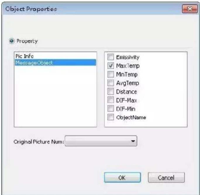
Figure 40
8.3.13. Line analysis
In order to use this function, users have to add lines to the added pictures in "Image Setup" beforehand.
Select "Line Analysis" in tool bar, click right mouse button and choose "Attribute Settings". Then the menu bar pops up, as shown in figure 41. According to needs, users can check grid line, legend and lines. As shown in figure 42.
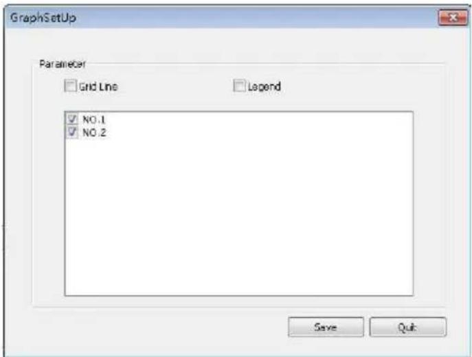
Figure 41
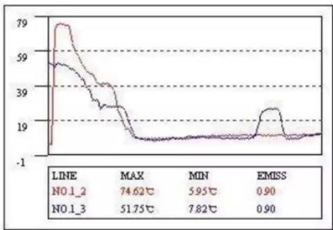
line
| LINE | MAX | MIN | EMISS | |--------|--------|--------|--------| | NO.1_2 | 74.62°C| 5.95°C | 0.90 | | NO.1_3 | 51.75°C| 7.82°C | 0.90 |Figure 42
8.3.14. Histogram
This function aims to display the line analysis in histogram. And users also need to add lines to the added pictures in "Image Setup" beforehand.
Select "Histogram" in tool bar, click right mouse button and choose "Attribute Settings". Then the menu bar pops up, as shown in figure 43. Users can choose the picture, measuring line, histogram number and colour. And you can add grind line according to needs.
There is an example in the figure 44.
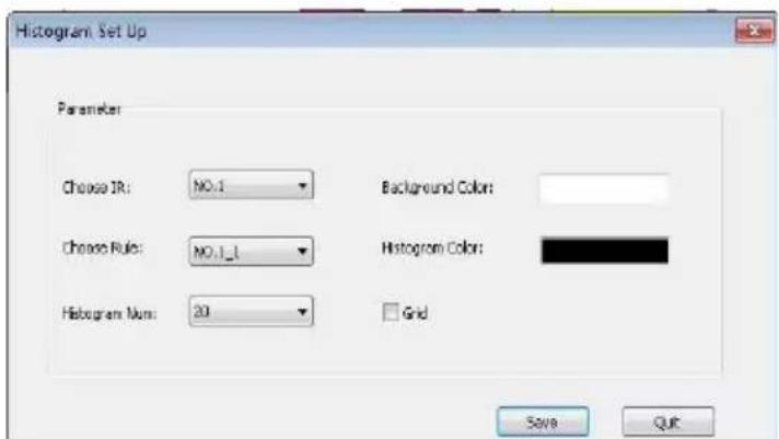
Figure 43
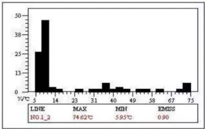
histogram
| %/°C | Value | |---|---| | 5 | 25 | | 14 | 49 | | 23 | 2 | | 31 | 2 | | 40 | 6 | | 49 | 2 | | 58 | 2 | | 67 | 2 | | 75 | 6 |Figure 44
8.3.15. Page attribute
Click right mouse button at the blank of the template, and select the option "Page". Here, the page attribute can be set up to "Cover Page", "Head Page", "Content Page" and so on.
If all pages are “Content Page”, users can add any number of pages, or any number of pictures on the same page. If one of the pages are not “Content Page”, then users can only add one page of “Content Page” which just has one single picture.
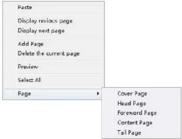
Figure 45
8.3.16. Video transmission
a. Preparation: USB Driver Installation of C-type Win10
If users prefer connecting device to PC by USB, you'd confirm that you have installed the USB driver files firstly! For some devices, USB driver files need to be installed manually!
There are the installation steps.
Firstly, please click the win button. Then click "Settings", and in this menu, please click "Update & security". Here, select "Recovery", and then click "Restart now" which is at the menu of "Advanced startup".
Waiting for some seconds, a new interface will pop up automatically. Please select "Troubleshoot" here, and click "Startup settings". Then click "Restart". In the new interface, press 7 in the number keyboard to select "Disable driver signature enforcement".
Thirdly, select "Set up→System setup" in the device, and then select "Video" in the "USB" option. And then connect the device with PC by USB wire.
After connecting and restarting, please open the "Device manager", and then find the corresponding device here. Right-click it and select "Update Driver Software", then click "Browse my computer for driver software", and add the file folder of driver.
b. IR device
Please connect the device to the PC firstly. There are two connecting ways.
The first one is to select "Setup → System Setup → USB", and then select video as transmission mode. By this way, please confirm the condition of USB driver files.
Open the software, Select , and then the "video player" box will appear. As shown in figure 46 and 47.
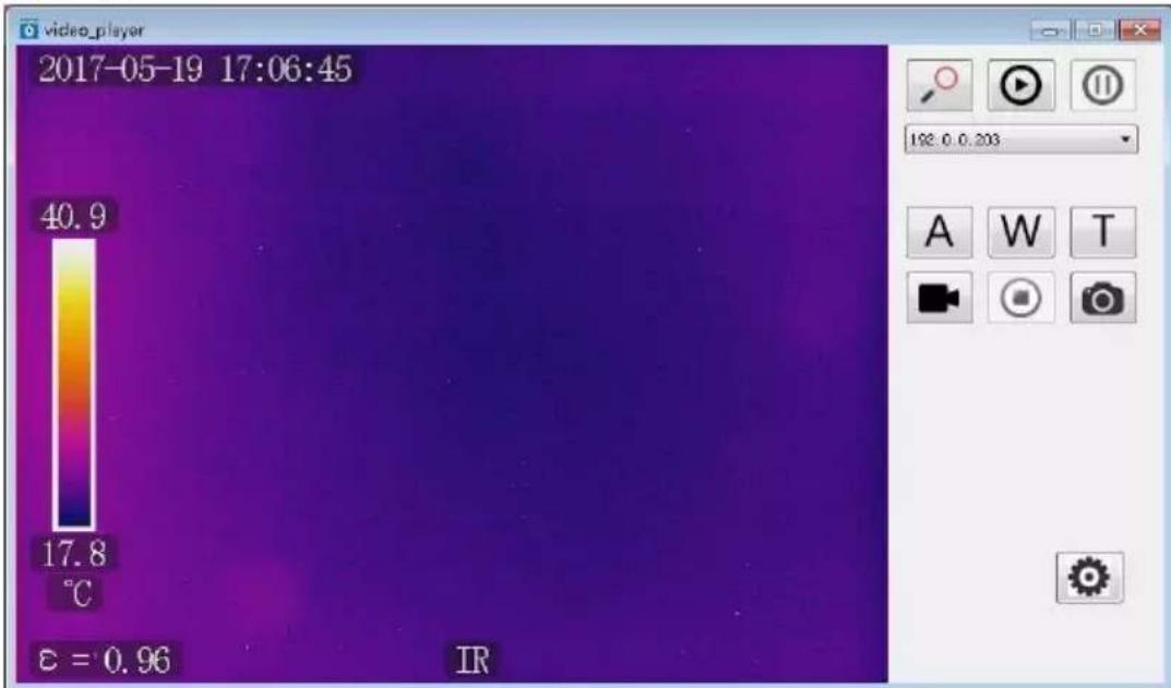
Figure 46
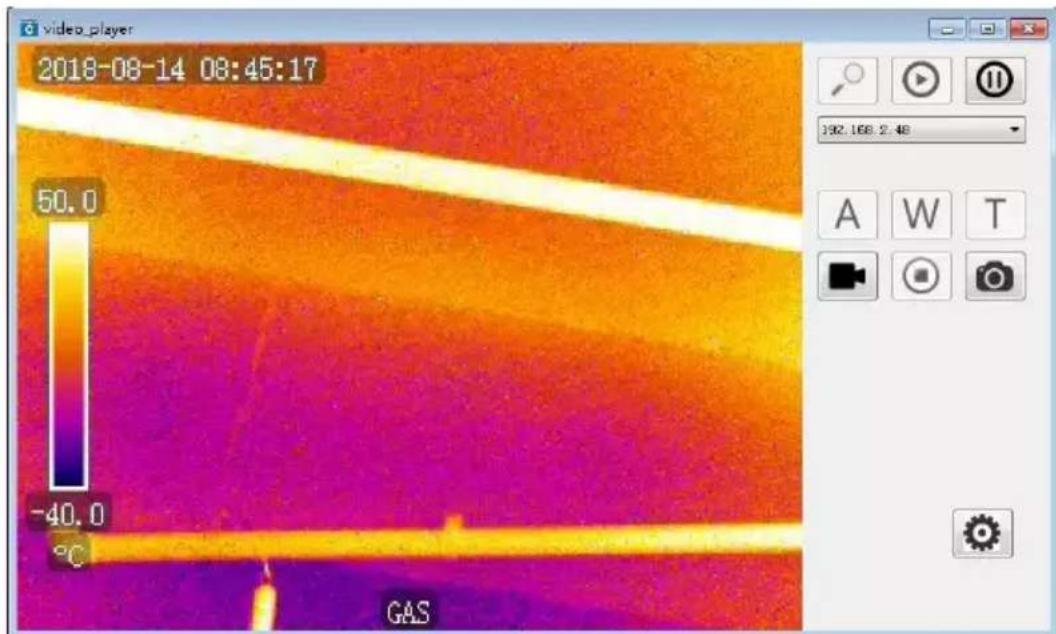
Figure 47
Click and users can reach the devices nearby. Click to connect the device, and click to disconnect. the device box can help users to select the devices they need.
For IR devices, there are two types of devices. For one kind of device, it could merely be shown as USB instead of the
IP address in the device box. In this situation, the functions of A, W and T are unavailable. For another kind, the device box shows the IP address, and the functions of A, W and T are available. Users can achieve auto focusing when you click, and adjust far-focus or near-focus when you click W or . T
For Gas devices, A, W and T are unavailable as gas device don't have the function of auto focusing.
Click record videos or stop recording. Click to take photos. Click to set up the save path of videos and photos.
c. UV device
Please connect the device to the PC firstly. There are two connecting ways.
The first one is to select “Setup → System Setup → USB”, and then select video as transmission mode. By this way, please confirm the condition of USB driver files.
Open the software, select , and then the "video player" box will appear. As shown in figure 48.
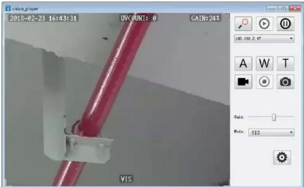
Figure 48
Click and users can reach the devices nearby. Click to connect the device, and click to disconnect. 192.168.1.119 can help users to select the devices they need.
Click A, W or T, users can achieve auto focusing, far-focus or near-focus. Click to record videos or stop recording. Click to take photos. Click to set up the save path of videos and photos. Click to adjust the gain and mode.
9. Other information
9.1. Cleaning and maintenance
The casing and accessories of the camera may be cleaned with a soft, damp cloth using dilute all-purpose detergents. Do not use any solvents or cleaning agents (powders, pastes, etc.) as they can damage or scratch the casing
Only clean the lens by compressed air or special tools.
The electronic circuits of the camera do not require adjustments, or maintenance.
When drying the camera and accessories do not exceed the maximum storage temperature.
9.2. Storage
When storing the camera observe the following:
- make sure that the camera is dry and is stored in a dry place
- if the device is to be stored for longer time remove the battery
- the device must be stored in a dry place at the temperature specified in the technical specifications.
9.3. Dismantling and disposal
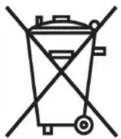
Disused and scrapped electric and electronic equipment should be disposed of safely and ecologically responsibly according to local regulations, i.e. it must not be placed with waste of another kind.
Scrap electronic equipment should be sent to a collection point in accordance with the law of waste electrical and electronic equipment.
Before the equipment is sent to a collection point do not dismantle or disassemble any part of the camera.
Observe local regulations concerning the disposal of electronic waste, packaging, and expired batteries.
natural_image
Pure electrical circuit lines without any symbols9.4. Transport
Always carry the camera and accessories in its original packaging or carrying case. Never carry the camera loose as it may be damaged due to shock and vibration. It is recommended to remove the battery from the camera during transport.
10. Technical specifications
UV optical parameters:
- Image .... monochrome video
- Corona image rendering .... white, red, blue
- Minimum UV sensitivity 2.2 x 10^-18 W / cm ^2
- Minimum Discharge Detection 1 pC at 10 meters
- Spectral Range....UV 240 - 280 nm
- Field of view (HxW)....5.5° x 4.0°
- Focus ....automatic or manual
- Focus range....above 2 m
- Detector life ....no degradation
- Frequency ....50Hz
Visible optical parameters:
- Image......true colour
- Overlay accuracy for UV/visible radiation image......better than 1 milliradian
- Minimum Sensitivity 0.1 lux
- Zoom 25x optical and 12x digital
Display:
- Type 5.7" VGA TFT, folding touch-screen
- Video standard ...... PAL/NTSC selectable
- Display Modes.... Mixed (UV + visible) / UV only / Visible radiation only
Processing and Communication:
- Video standard ......H.264
- Alarms....audio, LED
- Operation ....buttons and touch-screen
- Audio module ...... Microphone input for voice notes, headphone output
- GPS Module....built-in
Data Storage:
- Memory Type ....SD memory card
- Image format ....JPG
- Video Format.... AVI
- Memory ....8000 photos or up to 4 hours of video (for 2GB card)
- File Transfer .... USB, card reader
Power system:
- Rechargeable....Li-Ion battery, dedicated
- Power Consumption .... 10W
- Charging.... via power adapter or external charger
- Mains....power adapter 110...240V AC, 50/60 Hz / 12 V DC, 3.8 A
- Power supply from a car socket 9...14 V, 10 VA
- Battery operating time....about 2 hours
Other:
- Degree of enclosure protection acc. to EN 60529 IP54
- Operating temperature....-10°C...+50°C
- Storage temperature....-25°C...+60°C
- Humidity 100%...95%, non-condensing
- Weight....2.5 kg
- Dimensions 238 x 165 x 91 mm
- Video Output ....CVBS
- Audio input / output......combined jack for microphone and headphones / headset
11. Manufacturer
The manufacturer of the device and provider of guarantee and post-guarantee service:
SONEL S.A.
Wokulskiego 11
58-100 Świdnica
Poland
tel. +48 74 884 10 53 (Customer Service)
e-mail: customerservice@sonel.com
web page: www.sonel.com
NOTE
Service repairs must be performed only by the manufacturer.
NOTES
NOTES
NOTES
SONEL S.A.
Wokulskiego 11
58-100 Świdnica
Poland
Customer Service
tel. +48 74 884 10 53
e-mail: customerservice@sonel.com
www.sonel.com
- USER MANUAL
- CORONA CAMERA
- UV-260
- CORONA CAMERA UV-260
- Main features of UV-260:
- CONTENTS
- Technical specifications .... 40
- Manufacturer 41
- Introduction
- Safety
- WARNING:
- NOTE
- WARNING
- The principle of the operation
- Electromagnetic radiation: visible, infra-red, ultraviolet
- Mechanism of corona discharge
- Why corona discharge?
- Detection of corona discharge
- Preparing the camera for operation
- External design of the camera
- Mounting on a tripod
- Moving the camera
- CAUTION!
- Ports and buttons
- External ports
- Layout and functions of buttons
- Navigation buttons
- Operating mode buttons
- Control of power supply / charging and alarm - corona discharge indicator
- Operation and battery charging
- Inserting the battery
- Charging the battery
- WARNING.
- Guidelines for using the battery
- Working with UV-260 camera
- Operation of the buttons
- Recording a video
- Recording a static image
- Switching the image mode
- "Freezing" displayed image
- Changing the focus mode
- Gain adjustment
- Zoom
- Manual focus
- Zooming in
- Playing a voice note
- Zooming UV+ image
- Operating the menu
- Main menu
- Image Settings
- Video
- Image
- System
- Sub-menu "System Settings"
- "Sonel UV Analyse" software
- System requirements
- Software operation
- Starting-up software
- Interface
- Main function area
- a. File
- b. View
- c. Insert
- d. Setup
- e. Help
- Toolbar
- Template selection
- a. Blank template
- b. IR template
- c. UV template
- d. Gas template
- Appearance setting & font setting
- Cancel
- Line
- Edit box
- Add pictures
- a. Original picture
- b. Picture box
- c. Logo
- d. UltraMax picture
- It is not available for the device without ultramax function.
- Image setup
- a. IR non-gas image
- b. IR gas image
- Audio play
- List box
- Vertical list
- Line analysis
- Histogram
- Page attribute
- Video transmission
- a. Preparation: USB Driver Installation of C-type Win10
- b. IR device
- c. UV device
- Other information
- Cleaning and maintenance
- Storage
- Dismantling and disposal
- Transport
- Technical specifications
- UV optical parameters:
- Visible optical parameters:
- Display:
- Processing and Communication:
- Data Storage:
- Power system:
- Other:
- Manufacturer
Brand : Sonel
Model : UV-260
Category : Measurement