MIC-5010 - Measurement Sonel - Free user manual and instructions
Find the device manual for free MIC-5010 Sonel in PDF.


| Product Type | Micro-ohmmeter |
| Brand | Sonel |
| Model | MIC-5010 |
| Measurement Range (Resistance) | 0.1 µΩ to 1999 Ω |
| Test Current | Up to 10 A (selectable) |
| Measurement Method | 4-wire (Kelvin) connection |
| Accuracy | ±(0.25% reading + 0.05% range) |
| Display | Backlit LCD, 4 digits |
| Power Supply | Rechargeable Ni-MH battery pack (7.2 V) |
| Operating Time (Battery) | Approx. 8 hours continuous |
| Charging Time | About 4 hours |
| Dimensions | 220 × 110 × 60 mm |
| Weight | 1.2 kg (including battery) |
| Safety Category | CAT IV 600 V, CAT III 1000 V |
| Protection Type | Double insulation, IP54 (case closed) |
| Memory | Up to 990 measurement results |
| Interface | USB for data transfer |
| Accessories Included | Test leads, Kelvin clips, charger, USB cable, carrying case |
| Applicable Standards | IEC 61557-4, IEC 61010-1 |
| Maintenance | Clean with damp cloth; recalibrate annually |
| Repairability | Serviceable by authorized Sonel centers; spare parts available |
Frequently Asked Questions - MIC-5010 Sonel
User questions about MIC-5010 Sonel
0 question about this device. Answer the ones you know or ask your own.
Ask a new question about this device
Download the instructions for your Measurement in PDF format for free! Find your manual MIC-5010 - Sonel and take your electronic device back in hand. On this page are published all the documents necessary for the use of your device. MIC-5010 by Sonel.
USER MANUAL MIC-5010 Sonel
natural_image
Line drawing of an open electrical testing device with control panel and display (no text or symbols)USER MANUAL
INSULATION RESISTANCE METERS
MIC-5010 • MIC-5005
MIC-5010
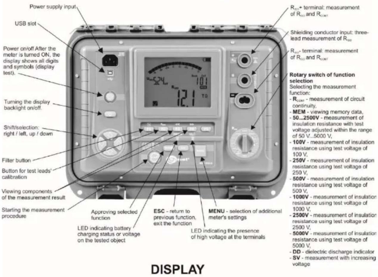
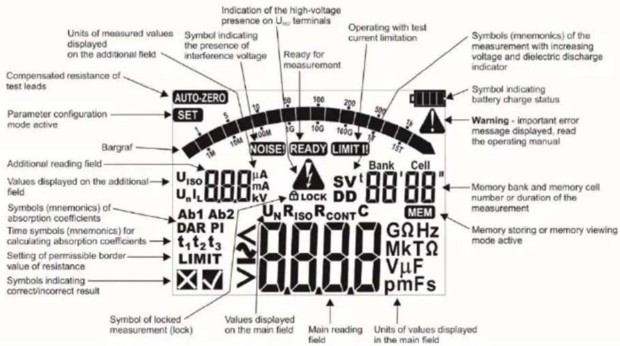
USER MANUAL
INSULATION RESISTANCE METERS MIC-5010 • MIC-5005
CE
SONEL S.A.
Wokulskiego 11
58-100 Świdnica
Poland
Version 1.23 22.01.2025
MIC-5010 and MIC-5005 meters are modern, high-quality, easy and safe in operation. Please acquaint yourself with the present manual in order to avoid measuring errors and prevent possible problems related to operation of the meter.
CONTENTS
1 Safety 4
2 Meter configuration ....5
3 Measurements....8
3.1 Measurement of insulation resistance....8
3.1.1 Double-lead measurement....9
3.1.2 Three-lead measurement....15
3.1.3 Measurements with increasing voltage - SV 17
3.1.4 Dielectric Discharge Indicator – DD....19
3.2 MIC-5010 Low-voltage measurement of resistance 21
3.2.1 Measurement of resistance of protective conductors and equipotential bonding with ±200 mA current....21
3.2.2 Calibration of test leads....23
3.3 Tightness test of MV cable jacket.... 24
4 Memory of measurement results 24
4.1 Storing the measurement results in the memory 25
4.2 Viewing memory data.... 27
4.3 Deleting memory data 27
4.3.1 Deleting bank data....27
4.3.2 Deleting the whole memory....29
5 Data transmission....30
5.1 Set of accessories to connect the meter to a PC 30
5.2 Data transmission through USB port 30
5.3 Data transmission with Bluetooth module 31
5.4 Data transmission with OR-1 wireless module 32
6 Software updates....33
7 Power supply of the meter....34
7.1 Monitoring the power supply voltage 34
7.2 Battery power 34
7.3 Charging rechargeable battery 35
7.4 Mains power 35
7.5 General principles for using Li-Ion rechargeable batteries 36
7.6 General principles for using gel (lead) rechargeable batteries 36
8 Cleaning and maintenance 37
9 Storage....37
10 Dismantling and utilisation....37
11 Technical specifications ....38
11.1 Basic data 38
11.2 Other technical data 40
11.3 Additional data 41
11.3.1 Additional uncertainties according to IEC 61557-2 ( R_SO )......41
11.3.2 Additional uncertainties according to IEC 61557-4 (R CONT)....41
12 Manufacturer 41
1 Safety
The MIC-5010 and MIC-5005 meters are designed for performing check tests of protection against electric shock in mains systems. The meters are used for making measurements and providing results to determine safety of electrical installations. Therefore, in order to provide conditions for correct operation and accuracy of obtained results, the following recommendations must be observed:
- Before you proceed to operate the meter, acquaint yourself thoroughly with the present manual and observe the safety regulations and specifications provided by the producer.
- Any application that differs from those specified in the present manual may result in a damage to the device and constitute a source of danger for the user.
- The MIC-5010 and MIC-5005 meters must be operated only by appropriately qualified personnel with relevant certificates authorising the personnel to perform works on electric systems. Operating the meter by unauthorised personnel may result in damage to the device and constitute a source of danger for the user.
- During measurements of insulation resistance, dangerous voltage up to 5 kV occurs at the ends of test leads of the meter.
- Before the measurement of insulation resistance you must be sure that tested object is disconnected from the power supply.
- During the measurement of insulation resistance do not disconnect test leads from the tested object before the measurement is completed (see par. 3.1.1.); otherwise the capacitance of the object will not be discharged, creating the risk of electric shock.
- When measuring the resistance of a cable, ensure that the other end of the cable is protected against accidental contact.
- Using this manual does not exclude the need to comply with occupational health and safety regulations and with other relevant fire regulations required during the performance of a particular type of work. Before starting the work with the device in special environments, e.g. potentially fire-risk/explosive environment, it is necessary to consult it with the person responsible for health and safety.
- It is unacceptable to operate:
⇒ a damaged meter which is completely or partially out of order,
⇒ a test leads with damaged insulation,
⇒ a meter stored for an excessive period of time in disadvantageous conditions (e.g. excessive humidity). If the meter has been transferred from a cool to a warm environment with a high level of relative humidity, do not start measurements until the meter is warmed up to the ambient temperature (approximately 30 minutes).
- One should remember that when the word GREE appears on the display, it indicates insufficient voltage of power supply and the need to recharge the batteries.
- The symbols ErrX, where X is a number between 0 to 9, indicate incorrect operation of the meter. If after restarting the device this situation is repeated - it indicates that the meter is damaged.
- Before measurement, choose a correct measurement function and make sure that test leads are connected to respective measuring terminals.
- Do not power the meter from sources other than those listed in this manual.
- The R _ISO inputs of the meter are protected electronically from overload (e.g. due to having been connected to a live circuit) up to 660V rms for 60 seconds.
- Repairs may be performed only by an authorised service point.
Note:
Due to continuous development of the meter's software, the actual appearance of the display in case of some of the functions, may slightly differ from the display presented in this operating manual.
ATTENTION!
To display the correct battery discharge status, it is necessary to completely discharge and then fully charge the battery, before starting the regular use of the meter.
Note:
An attempt to install drivers in 64-bit Windows 8 may result in displaying "Installation failed" message.
Cause: Windows 8 by default blocks drivers without a digital signature.
Solution: Disable the driver signature enforcement in Windows.
2 Meter configuration
①
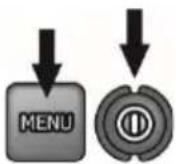
Turn on the meter by pressing and holding the MENU button.
②
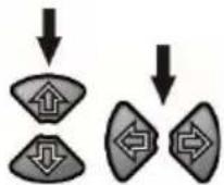
The buttons and are used to set the parameter value, while the and buttons move to the next parameter.
The setting sequence is as follows:
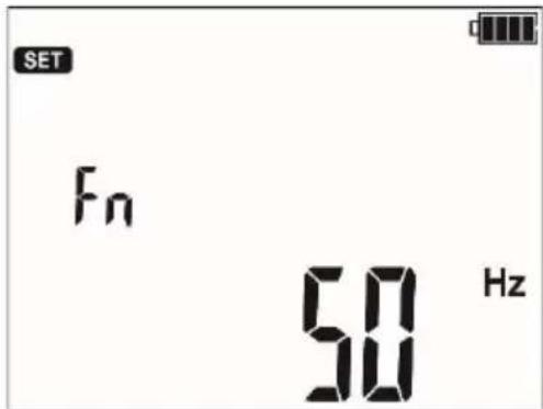
③
Rated grid frequency (50 Hz and 60 Hz).
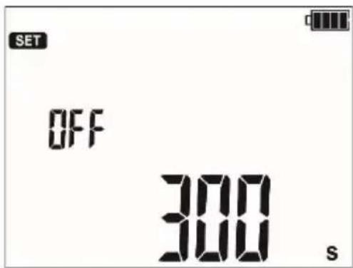
④
Auto-off time (300 s, 600 s, 900 s) or none (---).

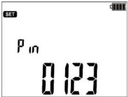
Pin, the digit being set is blinking. Moving to the next digit with the F3 and F4 buttons.
The same code must be entered in the computer programme for wireless transmission. It is used to prevent access of unauthorized persons to the meter via wireless connections (external entities).

Absorption coefficients for R_ISO : Ab1, Ab2 (or PI, DAR ()). Each change sets the t1, t2 and t3 to their default values: for Ab1/Ab2 t1=15s, t2=60, t3=0, and for PI/DAR t1=30, t2=60, t3=0).


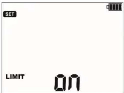
MIC-5010 Enabling (on) and disabling ( ) the limit settings.

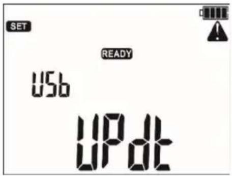
Software updates.
This topic is discussed in paragraph 6.

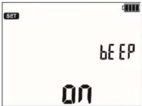
Enabling (or) and disabling ( ) off the buzzer.

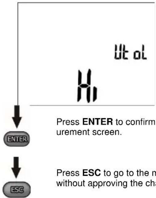
Test voltage accuracy: Hi - 0...5%, Lo - 0...10%
flowchart
graph TD
    A["ENTER"] --> B["ESC"]
    C["Ut ol"] --> D["H1"]
    D --> E["Press ENTER to confirm urement screen."]
    F["Press ESC to go to the m without approving the cha"] --> G["End"]

Press ENTER to confirm and go to the measurement screen.
Press ESC to go to the measurement screen without approving the changes.
Note:
To restore factory settings, press and hold the ON/OFF button for more than 5 seconds.
3 Measurements
Notes:
- The result of the latest measurement is remembered by the meter until a next measurement is started or the measuring function is changed by means of the rotary switch. It is displayed for 20 s. Then it may be recalled by pressing ENTER, also after the meter is turned off and turned back on again.
WARNING:
During a measurement, switching of the range switch is forbidden because it may damage the meter and pose a threat to the user.
3.1 Measurement of insulation resistance
WARNING:
The tested object must not be live.
WARNING:
Take particular care during cable measurement. The risk of electric shock is present also after discharging their capacitance by the meter, as the voltage can be rebuilt automatically. Therefore, it is recommended to:
- connect the working cores of the cable to its grounded shield or local grounding before measurement,
- disconnect the grounding of the cores only after connecting the meter's test leads to the cable and only then start the measurement,
- after measuring and discharging the cable by the meter, ground the working cores as in the first step,
- disconnect the grounding of the cores just before applying the operating voltage to the cab
WARNING:
During measurements, it is recommended to use electrical insulating personal protection equipment, which reduces the risk of touching the wires that may pose a threat to the user.
Note:
During measurement, especially of high resistances, make sure that test leads do not touch each other and probes (crocodile clips), because such a contact may cause the flow of surface currents resulting in additional error in measurement results.
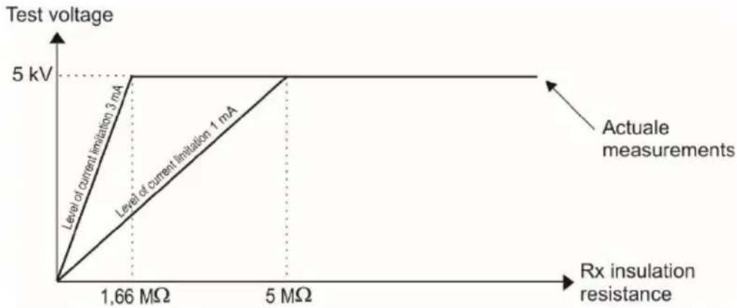
The converter output current I _sc is limited at a level of 1.2 mA or 3 mA. Activation of current restriction is indicated with a continuous audible signal. The measurement result is then correct, but the test voltage on the terminals is lower than the voltage selected before the test. Current limitation can happen in the first stage of a measurement due to the object's capacitance becoming charged.
line
| Rx insulation resistance | Test voltage | | ------------------------ | ----------- | | 1.66 MΩ | 3 mA | | 5 MΩ | 1 mA |Actual measurement voltage as a function of the measured insulation resistance R_x (for the maximum measurement voltage)
3.1.1 Double-lead measurement
①
pie
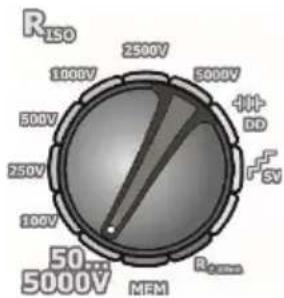
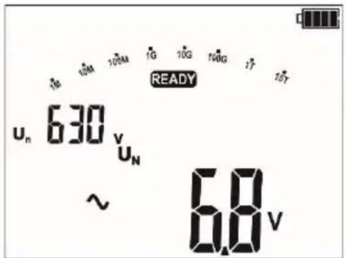
| Category | Value | |---|---| | R_LSO | 1000V | | 2500V | 2500V | | 5000V | 5000V | | 4+ | DD | | F_SV | (not labeled but visually visible) | | R_Earth | MFM | | 50... | 5000V |Set the rotary function selection switch in one of the R_iso positions, selecting at the same time the measurement voltage (positions 50 - 5000 V, selected with a step of 10 V in the range 50 V - 1 kV and with a step of 25 V between 1 kV and 5 kV). The meter is in the voltage measurement mode.
②

Press the MENU push-button to select:
- time used for calculating the absorption coefficients - (t1, t2, t3) and - the whole measurement time t, short-circuit current I sc and limit.
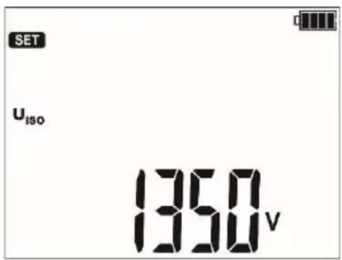
For the position of the selector between 50...5000 V, an additional option is available to select the test voltage U_n .
The buttons and arrows are used to set the parameter value, while the and buttons move to the next parameter.
The setting sequence is as follows:

Test voltage U_n ,

times - in sequence t1 (1...600 s), t2 (1...600 s, but >t1) and t3 (1...600 s, but >t2) and t (independent of t1, t2 and t3: 1 s...99 min 59 s),
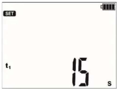
Setting of the times t1...t3.
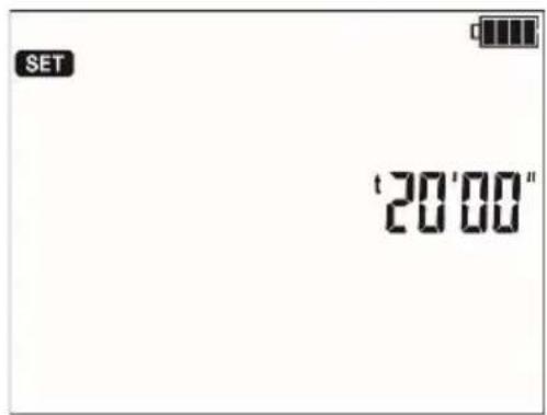
Setting of the time t.

Short-circuit current I_sc : 1,2 mA or 3 mA,
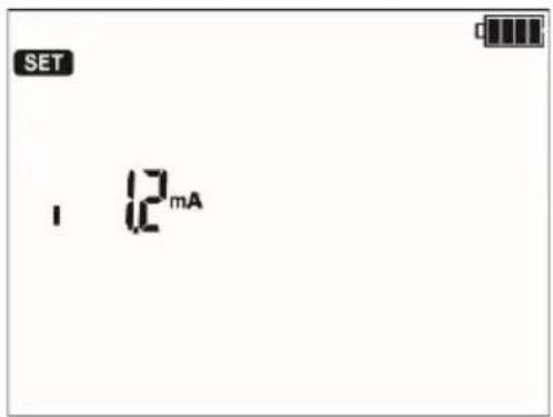
⑥
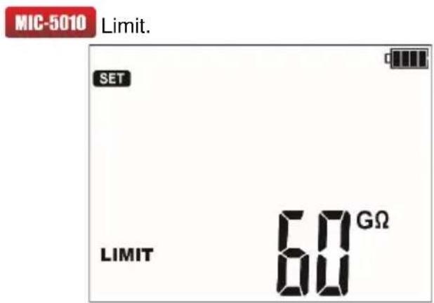
For Riso the limit is the minimum value. The limit range is from 1 kΩ to 15 TΩ.
The limit value is set using the and buttons. As the meter has many measurement sub-ranges, an algorithm for rapid increase or decrease of values is implemented. When holding the value key it changes very rapidly: first the hundreds, after 3 s tens, and after 3 s units etc. The limit setting is circular. The resolution of the set limit is related to the sub-range.
To deactivate the limit (displayed symbol ---) press the ↓ button while in the 1 kΩ position or the ↑ button while in the 15 TΩ position.
⑦
flowchart
graph TD
    A["ENTER"] --> B["OR"]
    C["ESC"] --> B["OR"]
Press ENTER to confirm settings (confirmed by beep) or press ESC to exit without saving the changes.
⑧
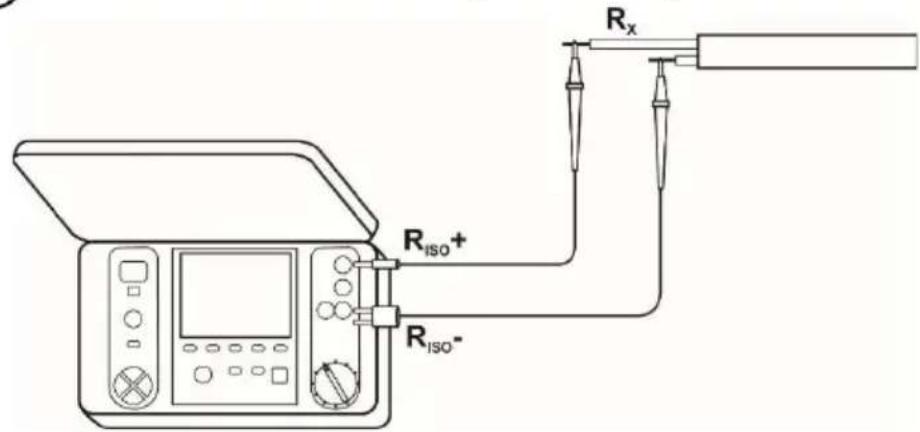
Connect test leads according to the drawing.
⑨
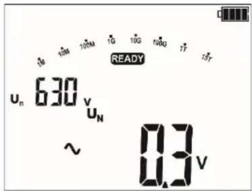
The meter is ready for measurement.
10
flowchart
graph TD
    A["START"] --> B["START"]
    B --> C["ENTER"]
Press and hold START push-button.
The measurement is performed continuously until you release the button or the pre-set time is reached.
In order to maintain (block) the measurement, press ENTER while holding the START - push-button pressed - the following symbol will be displayed, then release the button. In order to interrupt the measurement in this mode, press START again or press ESC.
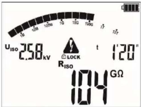
View of the screen during measurement.
During measurements controlled using the and buttons the display of the test voltage U_SO for the I_L leakage current may be changed.
The meter is equipped with an advanced digital filter for result stabilisation in difficult and unstable measurement conditions. When the F1 button is pressed before or during the measurement the meter will make calculations which will stabilise the fluctuations of the measurement results. The meter displays a filtered value of measurements for a specified time period. The filter is selected by pressing the F1 button i.e. after the first press the result shall be displayed as a filtered value from the last 10 s, after the second press from the last 30 s, then for 60 s and finally the filter is turned off "- -". The filter setting is circulating. The filter setting is erased automatically after the meter has been turned off or when the measurement function is changed using the rotary selector.
The ability to set the filter depends on the set t measurement time, for example when t=20 s it is only possible to set the filter for 10 s.
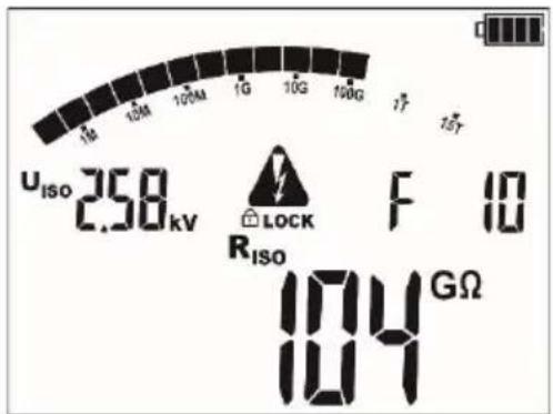
11
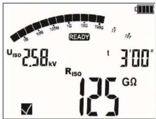
After the measurement is completed, read the result.
12
Use the F3 and F4 buttons (SCREEN) to see individual components of the result in the following order:
R_ISO I_L and C→Rt1 and It1→Rt2 and It2→Rt3 and It3→Ab1 (DAR)→Ab2(PI)→ R_ISO →limit(only
MIC-5010 ), where C – is the capacitance of the tested object.
Note:

During measurements of insulation resistance, dangerous voltage up to 5 kV occurs at the ends of test leads of the meter.

It is forbidden to disconnect test leads before the measurement is completed. Failure to obey the above instruction will lead to high voltage electric shock and make it impossible to discharge the tested object.
- Disabling t2 will also disable t3.
- Timer measuring the measurement time is started when U_ISO voltage is stabilized.
- Symbol LIMIT! informs of an operation with limited inverter power. If this condition persists for 20 seconds, the measurement is interrupted.
- A short tone informs of passing 5 s periods of time. When the timer reaches characteristic points (tx times), then for 1 s a symbol (mnemonic) of this point is displayed which is accompanied by a long beep.
- If any of the measured values of partial resistance is out of range, the value of the absorption coefficient is not displayed – the display shows dashes.
- During the measurement a yellow LED is lit.
- After completion of measurement, the capacitance of the object tested is discharged by shorting R_ISO + and R_ISO -terminals with resistance of 100 kΩ.
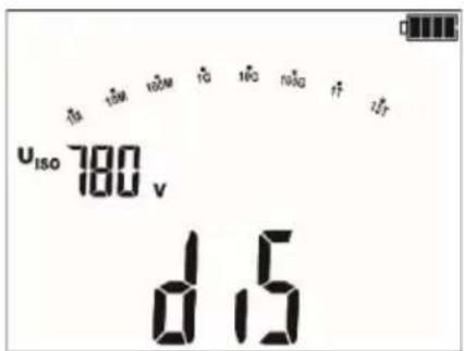
- Capacitance measurement is carried out only while the capacitance of the tested object is being discharged. If the R_ISO measurement is interrupted before the R_ISO value stabilizes, the discharge will start too early, so the capacitance measurement result may not be correct.
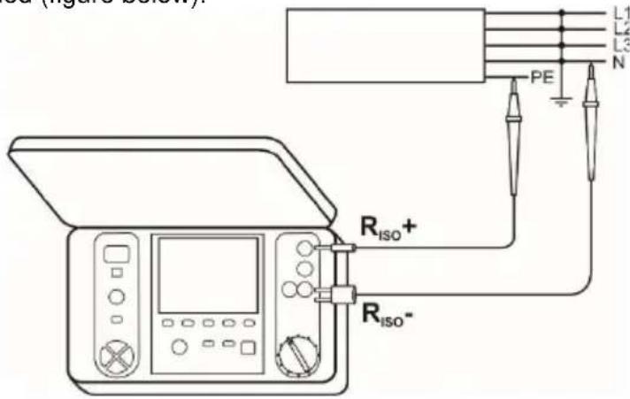
- In case of power cables measure the insulation resistance between each conductor and other conductors shorted and grounded (figure below).
Additional information displayed by the meter
 | Test voltage is present on terminals of the meter. |
 | Interference voltage lower than 50 V DC or 500 V AC, is pre-sent on the tested object. Measurement is possible but may be burdened with additional uncertainty. |
 | Activation of current limit. The symbol displayed is accom- panied by a continuous beep. |
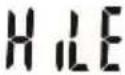 | Breakdown of the tested object insulation, the measurement is interrupted. The message appears after  y-ing for 20 s during the measurement, when the voltage pre-viously reached the nominal value. y-ing for 20 s during the measurement, when the voltage pre-viously reached the nominal value. |
| Un>50 V (for DC) or Un~>500 V (for AC)+two-tone, continu-ous beep + and LED lit in red | During the measurement, AC voltage appeared or the object cannot be discharged for 30 seconds. After 5 seconds the meter returns to its default mode - voltmeter. |
3.1.2 Three-lead measurement
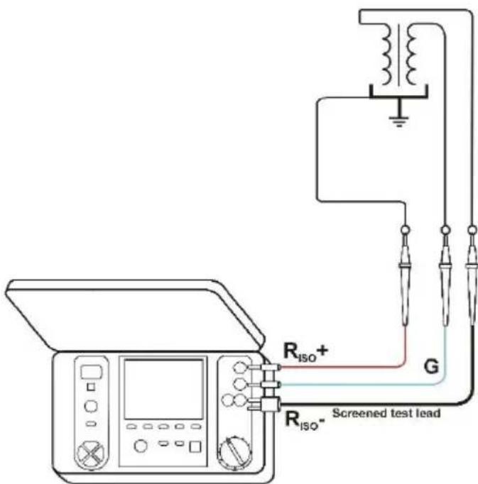
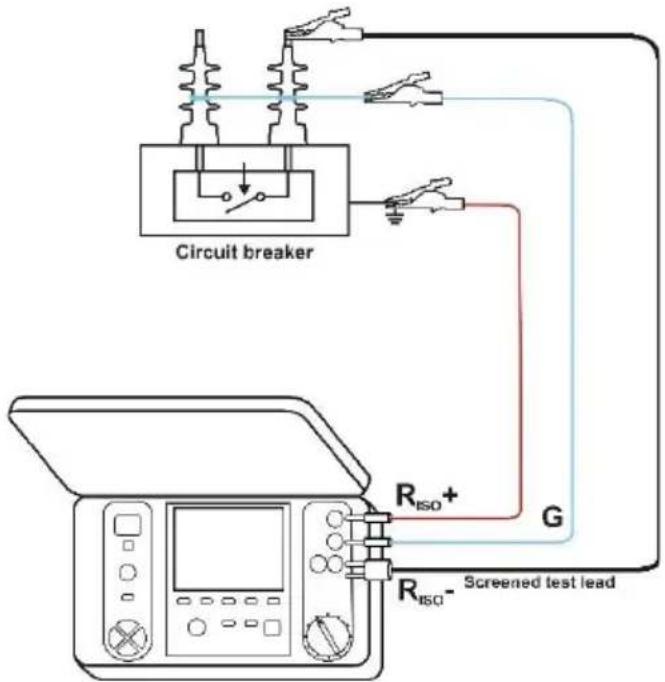
In order to eliminate the influence of surface resistance in transformers, cables, etc. the three-lead measurement is used, but do not connect the current measuring test lead R_iso - to large ground conductors. For example:
- at the measurement of inter-winding resistance of a transformer, G socket of the meter should be connected to the transformer tank;
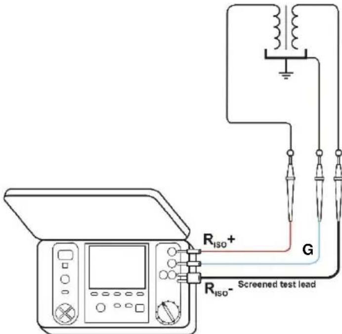
- when measuring the insulation resistance between one of the windings and the transformer's tank, connect G socket of the meter to the second winding:
- when measuring insulation resistance between one of the cable conductors and the cable shield, the effect of surface resistances (important in difficult weather conditions) is eliminated by connecting a piece of metal foil insulating the tested conductor with G socket of the meter;
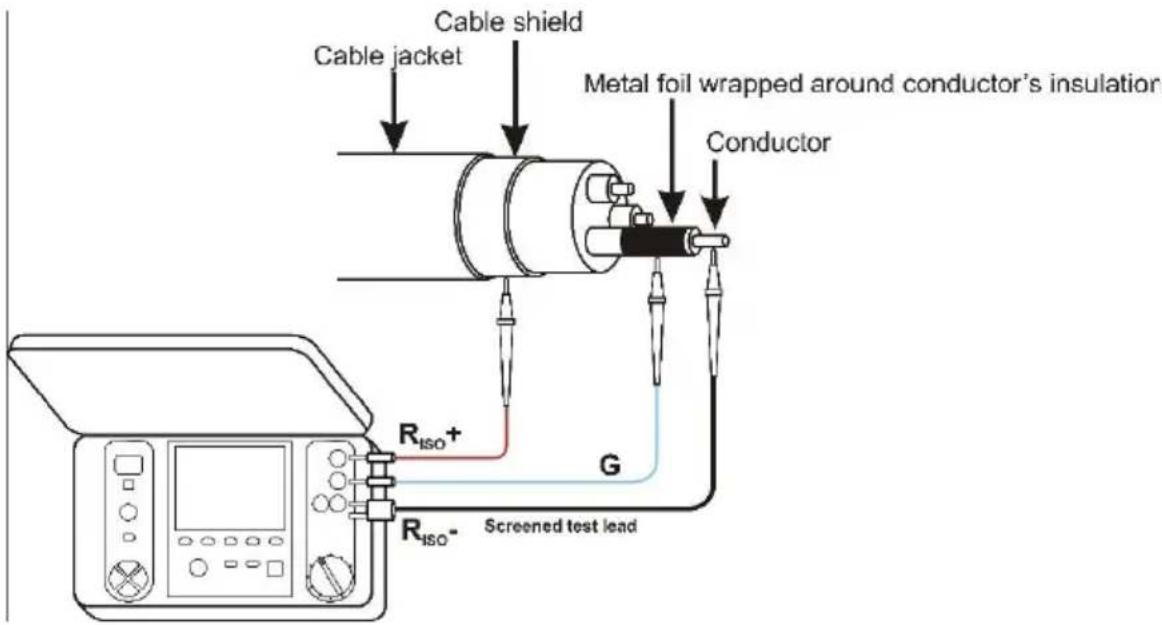
The same shall apply when measuring the resistance between two conductors of the cable, attaching to G terminal other conductors that do not take part in the measurement.
- at the measurement of insulation resistance of a high voltage circuit breaker, G socket of the meter should be connected to the terminals' insulators of the breaker;
3.1.3 Measurements with increasing voltage - SV
In this mode the meter performs a series of 5 measurements with increasing voltage; the voltage change depend on the set maximum voltage:
- 1 kV: 200 V, 400 V, 600 V, 800 V, 1000 V,
• 2.5 kV: 500 V, 1 kV, 1.5 kV, 2 kV, 2.5 kV, - 5 kV: 1 kV, 2 kV, 3 kV, 4 kV, 5 kV.
The end result for each of the 5 measurements is saved which is signalled by a beep and an appropriate icon.
①
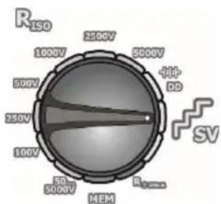
Set the rotary switch of function selection in the SV position. The meter is in the voltage measurement mode.
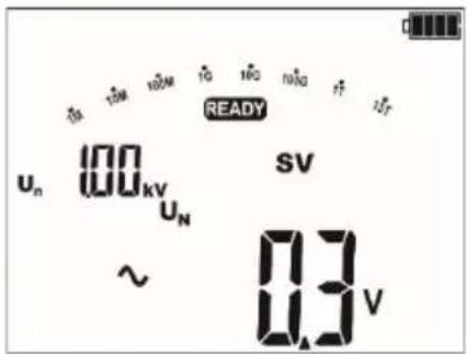
②

By pressing the MENU button the maximum measurement voltage selection, the duration for individual measurements and the short-circuit current I_sc may be selected.
The buttons and are used to set the parameter value, while the and buttons move to the next parameter.
The setting sequence is as follows:
③
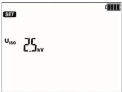
maximum (final) measurement voltage: 1 kV, 2.5 kV and 5 kV,
④
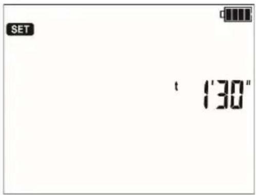
duration of individual measurements in the range between 30 s...5 min,
⑤
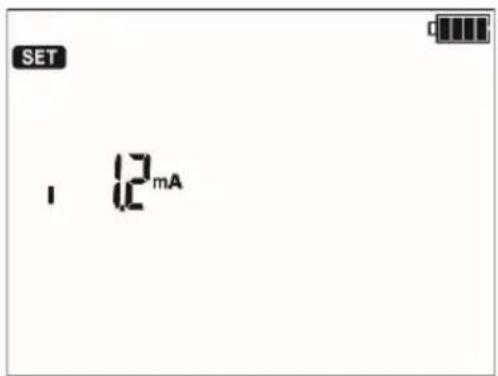
short-circuit current I_sc : 1.2 mA or 3 mA,
⑥
flowchart
graph TD
    A["ENTER"] --> B["OR"]
    C["ESC"] --> B["OR"]
Press ENTER to confirm settings or press ESC to exit without saving the changes.
⑦
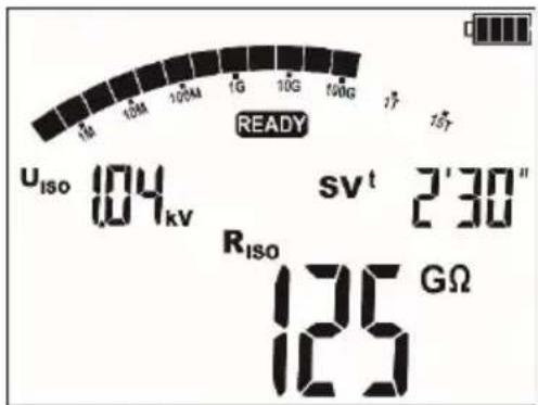
Execute the measurement.
After the measurement is completed, read the result.
⑧
Use F3 and F4 (SCREEN) to see individual components of the result in the following order: R_ISO , U_ISO , t I_L and C U_ISO1 and t1 alternatively with R_ISO1 and I_L1 U_ISO2 and t2 alternatively with R_ISO2 and I_L2 , where C - the capacity of the tested object.
Note:
- Further information, starting the measurement, displayed symbols, result readout and component view operate identically as the R_ISO measurement.
3.1.4 Dielectric Discharge Indicator – DD
In the dielectric discharge test the discharge current is measured after 60 seconds from the end of measurement (charging) of the insulation. The DD is a value characterising the insulation quality independent from the test voltage.
The measurement operates in the following way: first the insulation is charged with a current for a set period. If this voltage is not equal to the set voltage the object is not charged and the meter abandons the measurement procedure after 20 seconds. After the charging and polarisation is complete, the only current flowing through the insulation is the leakage current. Then the insulation is discharged and the total dielectric discharge current starts to flow through the insulation. Initially this current is the sum of the capacity discharge current, which fades quickly and the absorption current. The leakage current is negligible, because there is no test voltage.
After 1 minute from closing the circuit the current is measured. The DD value is calculated using the formula:
$$ D D = \frac {I _ {1 \min}}{U _ {p r} \cdot C} $$
where:
I_1 - current measured 1 minute after closing the circuit [nA],
U_pr – test voltage [V],
C - capacitance [μF].
The measurement result testifies to the insulation condition, you may compare it with the table below:
| DD value | Insulation condition |
| >7 | Bad |
| 4-7 | Poor |
| 2-4 | Not too good |
| <2 | OK |
①
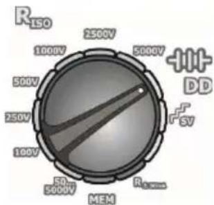
Set the rotary switch of function selection at DD. The meter is in the voltage measurement mode.
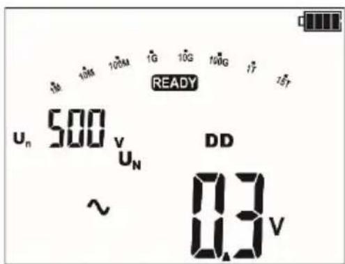
②
Press the MENU button to navigate to the test current and load time selection.
The buttons and are used to set the parameter value, while the hand buttons move to the next parameter.
The setting sequence is as follows:
③ charge time: 1 min...60 min,
④ charge voltage: 100 V, 250 V, 500 V 1 kV, 2.5 kV, 5 kV,
⑤ maximum charge current: 1,2 mA or 3 mA.
Note:
- In an environment with strong interferences the measurement may be affected by additional uncertainty.
3.2 Low-voltage measurement of resistance
3.2.1 Measurement of resistance of protective conductors and equipotential bonding with ±200 mA current
①
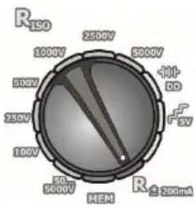
Set the rotary switch at the Rcont position.
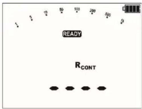
The meter is ready for measurement.
②

Press the MENU button to go to the limit setting.
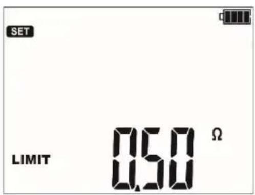
For R_CONT the limit is the minimum value. The setting limit reflects the function: from 0.01 Ω to 999 Ω. The value of the limit set in the same way as for R_ISO .
To deactivate the limit (displayed symbol ---) press the button while in the 1k position or the button while in the 999 position.
③
Connect the meter to the tested object. Trigger the measurement by pressing the START push-button.
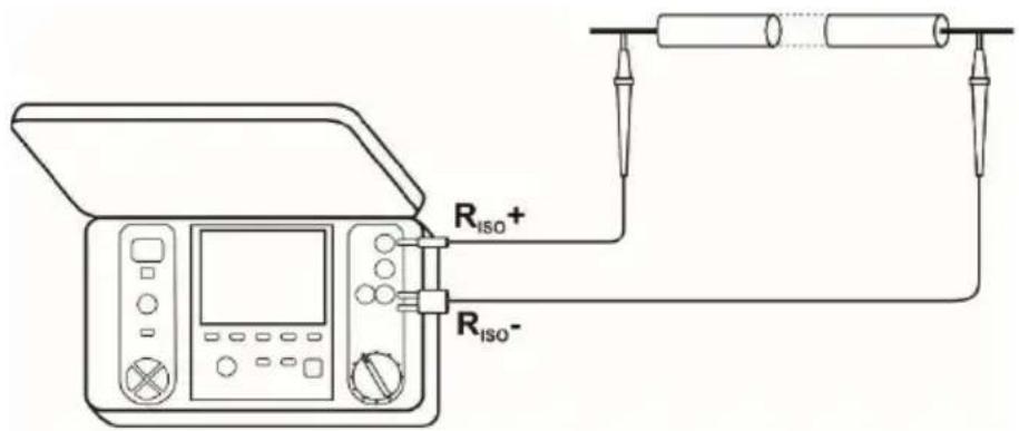
④
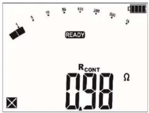
Read out the result.
Additional information displayed by the meter
| NOISE! | Interference voltage occurs on the tested object. The measurement is possible however it will be burdened with additional uncertainty that is specified in the technical data. |
| U_n > 10 V +two-tone, continuous beep + and LED lit in red | Interference voltage exceeds the allowable value, the measurement is blocked. |
3.2.2 Calibration of test leads
In order to eliminate the impact of the resistance of test leads on measurement result, the compensation (autozeroing) of resistance may be performed.
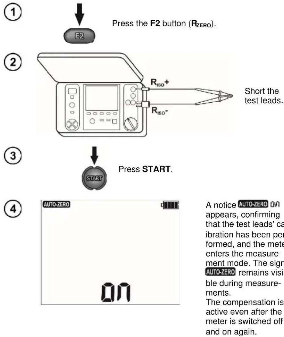
Press the F2 button ( R_ZERO ).
Short the test leads.
Press START.
A notice AUTO-ZERO ON appears, confirming that the test leads' cal- ibration has been per- formed, and the meter enters the measure- ment mode. The sign AUTO-ZERO remains visi- ble during measure- ments. The compensation is active even after the meter is switched off and on again.
⑤
In order to remove the calibration made (return to default calibration), perform the above-mentioned activities with test leads open; the sign of shall appear.
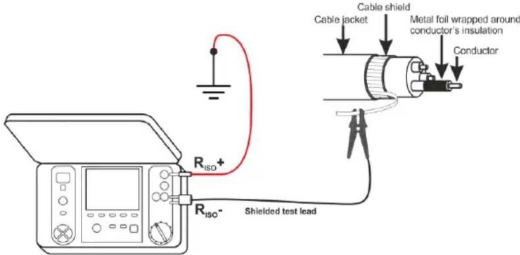
3.3 Tightness test of MV cable jacket
Tightness test of MV cable jacket consists of applying a test voltage between its metal sheath or its return conductor and the ground. During the measurement, pay attention to the value of I_L current.
The test voltage and the measurement time depend on the type of the tested object and test guidelines. For example, for a cable with polyethylene insulation:
- test voltage according to standard HD 620 S1: ≤5 kV,
- measurement time after voltage stabilization: 1-10 min,
- positive result according to HD 620 S1: when no ground fault has occurred.
4 Memory of measurement results
The MIC-5010 and MIC-5005 meters are equipped with a memory capable of storing 11880 single test results (990 cells, each may contain a set of measurements of: R SO and R CONT ). The whole memory is divided into 10 memory banks each of them containing 99 memory cells. Thanks to dynamic memory allocation, each of the memory cells can contain different quantity of single measurement results, depending on the needs. Optimal use of the memory can be ensured in this way. Each measurement result can be stored in a memory cell marked with a selected number and in a selected memory bank. Thanks to this, the user of the meter can, at his/her option, assign memory cell numbers to individual measurement points and the memory bank numbers to individual facilities. The user may also perform measurements in any chosen sequence and repeat them without losing other data.
Memory of measurement results is not deleted when the meter is switched off. Thanks to this, the data can be later read or sent to a computer. The number of a current memory cell or memory bank is not changed either.
Note:
- A single cell may contain either a R_ISO 2(3)p measurement result, a R_ISO SV, or DD.
- After entering the measurement result, the ID number of the cell is automatically increased.
- It is recommended to delete the memory after reading the data or before performing a new series of measurements that may be stored into the same memory cells as the previous ones.
4.1 Storing the measurement results in the memory
①
After the measurement is complete press ENTER and the meter shall enter the saving mode.
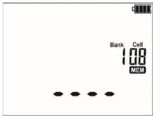
The cell is empty.
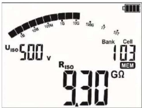
The cell is occupied by a result of the same type as the current result.
Use the F3 and F4 buttons (SCREEN) to see individual components of the result.
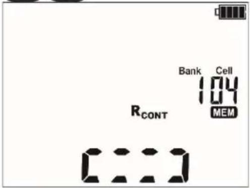
The cell is occupied by a result of a different type than the current result.
Use the F3 and F4 buttons (SCREEN) to see individual components of the result.
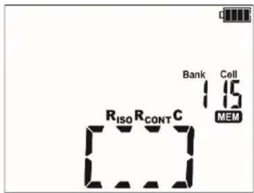
The cell is fully occupied.
Use the F3 and F4 buttons (SCREEN) to see individual components of the result.

The cell ID is changed using the hand while the bank ID is changed using the hand.

Press ENTER, to save the result in the memory. Saving is indicated by a triple beep and by a rectangle displayed on the main display field.
Press ESC to return to displayed result without saving.

If you try to store data in an occupied memory cell, the following warning message will appear:
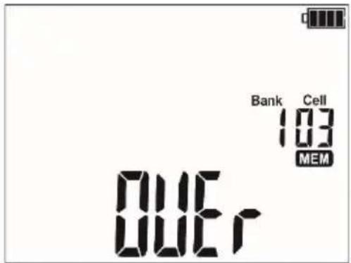

or
Press ENTER, to overwrite the result or ESC, to cancel saving.
Note:
- Complete set of results (main result and supplementary results) for a given measuring function and preset measurement settings are stored in the memory.
4.2 Viewing memory data
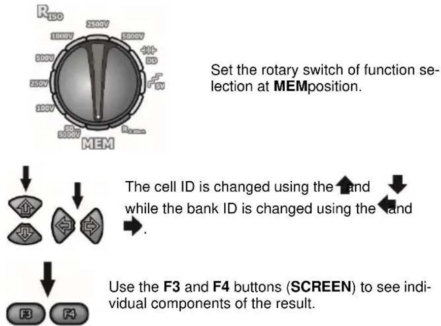
flowchart
graph TD
    A["Set the rotary switch of function selection at MEM position."] --> B["Cell ID: Cell ID is changed using the hand"]
    B --> C{While the bank ID is changed using the hand}
    C --> D["Use the F3 and F4 buttons (SCREEN) to see individual components of the result."]
    style A fill:#f9f,stroke:#333
    style B fill:#ccf,stroke:#333
    style C fill:#cfc,stroke:#333
    style D fill:#fcc,stroke:#333
Note:
- While viewing R_ISO results, the field of timer / memory displays alternately bank and cell numbers and the time in which the result was entered into memory. This applies to all R_ISO measurements.
4.3 Deleting memory data
You can delete the entire memory or its individual banks.
4.3.1 Deleting bank data
①
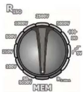
Set the rotary switch of function selection at MEMposition.
②
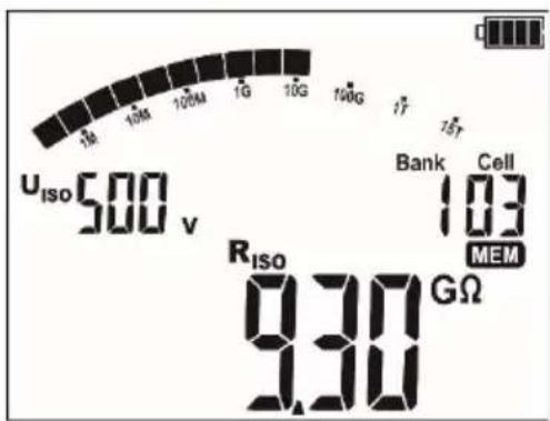
Set the bank number to be deleted using the and buttons. Set the cell ID using the and buttons in front of "1"...
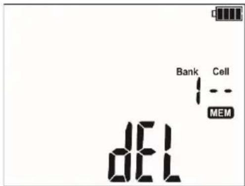
...the cell number disappears, and the symbol indicating the readiness to delete appears.
③
Press ENTERpush-button.
![[conf] Bank Cell MEM](/content/2026/05/982941/images/d9495a4ef7a647416a8686e8b26ee475bbc97726c1b1eaacbaf9a369496070b6.jpg)
and symbols appear, asking you to confirm deletion.
④
Press ENTER again. After deleting the bank, the meter beeps three times and sets the cell number as "1."
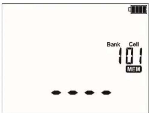
4.3.2 Deleting the whole memory
①
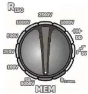
radar
| Category | Value | |---|---| | R_ISO | 1000V | | 2500V | 2500V | | 5000V | 5000V | | 41+ DD | 5000V | | F_SV | 5000V | | R_Dem | 5000V | | MEM | 5000V |Set the rotary switch of function selection at MEMposition.
②
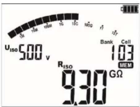
Set the bank ID using the ← and → buttons in front of "1"...
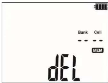
...the bank ID disappears, and the symbols displayed, indicating the readiness to delete.
③
Press ENTER push-button.
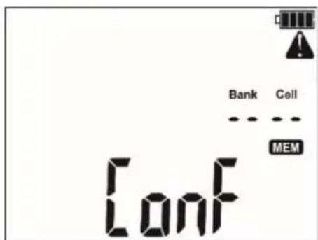
and symbols appear, asking you to confirm deletion.
④
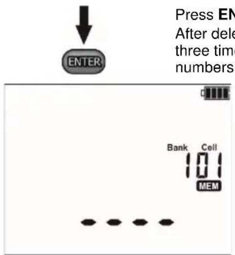
Press ENTER again.
After deleting the bank, the meter beeps three times and sets the bank and cell numbers as "1."
5 Data transmission
Remarks:
- Data transmission is not possible during the charging of rechargeable batteries.
Support for wireless data transmission
| Meter name | Bluetooth | OR-1 |
| Serial number / prefix | ||
| MIC-5010 | DP≥ B20469 | B20001 ... B20468 |
| MIC-5005 | ≥ B11082 | B10001 ... B11081 |
5.1 Set of accessories to connect the meter to a PC
In order to ensure the communication of the meter with a computer an USB cable is required or Bluetooth wireless module with an additional software (Sonel Reader, Sonel Reports Plus). If the required software has not been purchased with the meter, it may be obtained from the manufacturer or form an authorised distributor.
This software may be used for many devices manufactured by SONEL S.A. which are equipped with USB interface and /or OR-1 module / Bluetooth.
Detailed information is available from the manufacturer and distributors.
5.2 Data transmission through USB port
- Set the rotational function selector at MEM.
- Connect the cable to the USB port of the computer and the USB socket of the meter.
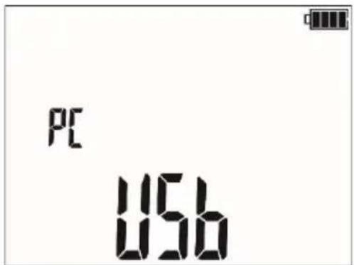
- Start the programme.
5.3 Data transmission with Bluetooth module
Firmware ≤1.30
- Set the rotary switch to MEM, press the MENU button.
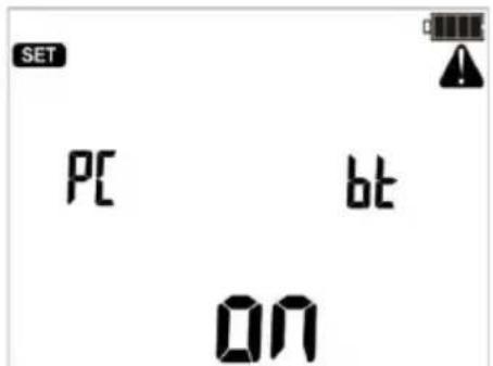
- Press ENTER to start the transmission.
Firmware 1.31+
- While holding down the MENU button, turn on the meter.
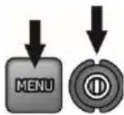
- After the configuration menu screen is displayed (chapter 2, step 3) use the buttons to go to the bt screen. Activate transmission with the ↑↓ buttons.
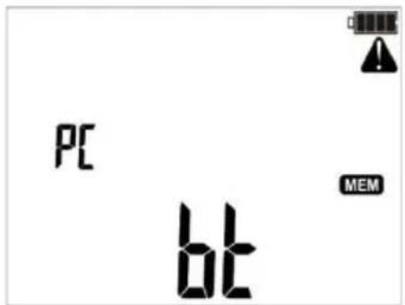
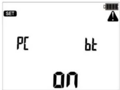
- Connect Bluetooth module to the USB socket of the PC, unless it is integrated into the PC.
- During the process of pairing the meter with a PC enter PIN code compatible with the PIN code of the meter defined in main settings..
- On the computer start data storing programme.
Firmware ≤1.30
The data transmission may be interrupted using the ESC button.
Firmware 1.31+
Exit from transmission mode - setting oFF according to step 2.
Note:

Standard pin for Bluetooth is "0123".
- With the USB cable active the wireless transmission is not possible.
5.4 Data transmission with OR-1 wireless module
- Set the rotary switch to MEM, press the MENU button.
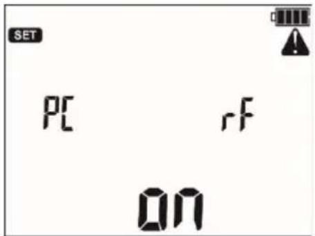
- Connect the OR-1 module to the USB socket of the PC and press ENTER.
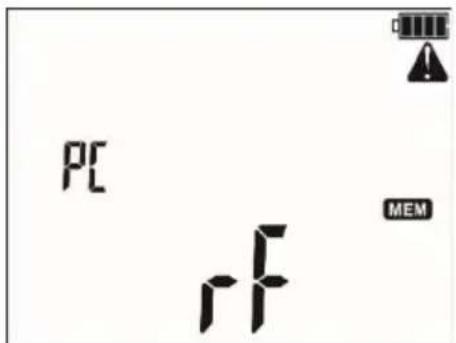
- If necessary, change the PIN code (par. 2).
- Start the data storing programme.
Note:

The standard pin for OR-1 is "123".
- The data transmission may be interrupted using the ESC button - the meter then enters the memory viewing mode.
- With the USB cable active the wireless transmission is not possible.
6 Software updates
Turn on the meter by pressing and holding the MENU button.
Using the ◀ and buttons display the following screen.
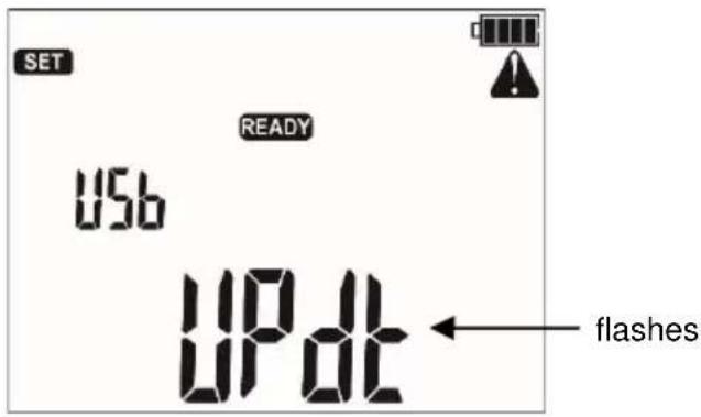

Connect the meter to the computer using an USB cable and press ENTER.
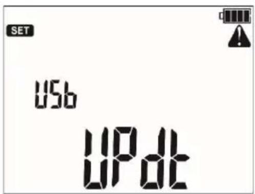
Follow the instructions of the software.
7 Power supply of the meter
7.1 Monitoring the power supply voltage
ATTENTION!
To display the correct battery discharge status, it is necessary to completely discharge and then fully charge the battery, before starting the regular use of the meter.
The charge level of rechargeable battery is indicated by the symbol in the right upper corner of the display on a current basis:
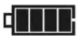
Battery charged.
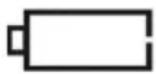
Battery low.
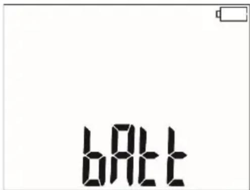
Battery fully discharged, all measurements are blocked.
The meter switches off automatically after 5 s.
7.2 Battery power
The meter is powered with a Li-Ion battery which may only be replaced in a repair shop.
NOTE:
In MIC-5010 up to SN: B20319 and MIC-5005 up to SN: B10644 gel batteries are used.
The charger is installed inside the meter and works only with the manufacturer's rechargeable battery. The charger is powered from the 230 V mains. It is also possible to power the unit from a car lighter using an optional 12 V / 230 VAC converter.
ATTENTION!
Do not power the meter from sources other than those listed in this manual.
7.3 Charging rechargeable battery
Charging commences once the power supply has been connected to the meter regardless of the fact whether the meter is on or off. Charging is indicated by changing status of battery charge. The rechargeable battery is charged in accordance with the "quick charge" algorithm – this process reduces the charging time to approx. 7 hours. The completion of the charging cycle is indicated by a full battery symbol and the lighting of a green LED. In order to turn the device off, unplug the power charger.
Note:
- As a result of interferences in the network it is possible that the process of charging of accumulator will finish too fast. When charging time is too short, turn off the meter and start charging again.
Additional information displayed by the meter
| Signalling | Condition |
| Green diode flashing 1 time per second, the battery symbol is displayed on the screen. | Charging in progress. |
| Green diode lighting continuously, the full battery symbol is displayed on the screen. | Charging finished. |
| Green diode flashing 2 times per second. | Charging error. |
| Green diode and the battery symbol flashing 2 times per second, the symbol is displayed on the screen. | Battery temperature too high.Measurements are blocked. |
7.4 Mains power
It is possible to carry out measurements during the charging process. For this purpose, in charge mode, press ESC button - the meter enters the measurement mode while continuing the charging process. Similarly, the process takes place when AC power supply is connected to the meter.
When the meter is turned off by button or by Auto-OFF, the charging process is not interrupted.
Additional information displayed by the meter
| Signalling | Condition |
| All the segments off the battery symbol flashing 1 time per second. | Charging finished. |
| Green diode and the battery symbol flashing 2 times per second, the land symbols are displayed on the screen. | Battery temperature too high.Measurements are blocked. |
7.5 General principles for using Li-Ion rechargeable batteries
- Store the half-charged battery pack in a plastic container placed in a dry, cool and well ventilated place and protect them from direct sunlight. The battery pack may be damaged if stored when fully discharged. The ambient temperature for prolonged storage should be maintained within the range of 5^ C... 25^ C.
- Charge the batteries in a cool, well-ventilated place at a temperature of 10^ C ... 28^ C. Modern fast chargers detect both too low and too high temperature of rechargeable batteries and react to the situation adequately. Too low temperature should prevent starting the process of charging, which might irreparably damage rechargeable batteries. The increase in temperature of the battery pack may cause electrolyte leakage and even its ignition or explosion.
- Do not exceed the charging current, as it may result in ignition or "swelling" of the battery pack. "Swollen" battery pack must not be used.
- Do not charge or use the batteries in extreme temperatures. Extreme temperatures reduce the lifetime of rechargeable batteries. Always observe the rated operating temperature. Do not dispose the battery pack into fire.
- Li-Ion cells are sensitive to mechanical damage. This kind of damage may cause its permanent damage and thus - ignition or explosion. Any interference in the structure of Li-ion battery pack may cause its damage. This may result in the ignition or explosion. A short-circuit of the battery poles "+" and "-" may permanently damage the battery pack or even cause its fire or explosion.
- Do not immerse Li-Ion battery in liquids and do not store in humid conditions.
- If the electrolyte contained in the Lithium-Ion battery pack, contacts eyes or skin, immediately rinse the affected place with plenty of water and consult a doctor. Protect the battery against unauthorised persons and children.
- When you notice any changes in the Lithium-Ion battery pack (e.g. changes in colour, swelling, excessive temperature), stop using the battery pack. Li-Ion batteries that are mechanically damaged, over-charged or excessively discharged are not suitable for use.
- Any misuse of the battery may cause its permanent damage. This may result in the ignition. The seller and the manufacturer shall not be liable for any damages resulting from improper handling Li-Ion battery pack.
7.6 General principles for using gel (lead) rechargeable batteries
- Store the rechargeable batteries in a dry, cool and well ventilated place and protect them from direct sunlight. Do not install them in a tightly closed container. While charging the batteries may produce flammable gases, which may be the cause of explosion if proper ventilation is not available. The best temperature for battery storage and operation is between 15°C and 25°C.
- Do not place batteries near equipment generating sparks, or store them in dusty areas.
- Do not connect the battery to any plastic elements or housing elements containing solvents. This may cause the battery body to unseal or crack.
- During storage of lead batteries they are self-discharged. The storage time without charging is dependent on ambient temperature: from 6 months at 20 °C to 2 months at 40 °C. In order to prevent excessive battery discharge, resulting in a significant reduction of their capacity and durability it is required to recharge them in specified intervals.
- Do not discharge the battery to a voltage below that, specified by its manufacturer. An attempt to recharge an over-discharged battery may cause a thermal hazard, which results in battery deformation or in change of the structure and distribution of the electrolyte in the battery as some of the water evaporates. This worsens the battery parameters similar to prolonged overcharging. Always recharge the battery immediately after discharging, even if it was not discharged to the recommended cut off voltage. Leaving a discharged battery for a couple of hours (sometimes even less than that if the discharge was very deep) will cause sulphating.
- Charging may only be performed using a charger with specific parameters and under the conditions set by their manufacturers. Failure to meet these conditions can lead to leakage, overheating or even an explosion.
8 Cleaning and maintenance
ATTENTION!
Use only the maintenance methods specified by the manufacturer in this manual.
The casing of the meter may be cleaned with a soft, damp cloth using all-purpose detergents. Do not use any solvents or cleaning agents which might scratch the casing (powders, pastes, etc.).
Clean the probe with water and dry it. Before the probe is stored for a prolonged period of time it is recommended to grease it with any machine lubricant.
The reels and test leads should be cleaned with water and detergents, and then dried.
The electronic system of the meter does not require maintenance.
9 Storage
In the case of storage of the device, the following recommendations must be observed:
- Disconnect all the test leads from the meter.
- Clean the meter and all its accessories thoroughly.
• Wind the long test leads onto the reels. - If meter is to be stored for a prolonged period of time, the batteries must be removed from the device.
- In order to prevent a total discharge of the accumulators in the case of a prolonged storage, charge them from time to time.
10 Dismantling and utilisation
Worn-out electric and electronic equipment should be gathered selectively, i.e. it must not be placed with waste of another kind.
Worn-out electronic equipment should be sent to a collection point in accordance with the law of waste electrical and electronic equipment.
Before the equipment is sent to a collection point, do not dismantle any elements.
Observe local regulations concerning disposal of packages, waste batteries and accumulators.
11 Technical specifications
11.1 Basic data
⇒ The abbreviation "m.v." used in the specification of accuracy denotes a standard measured value
AC / DC voltage measurement
| Display range | Resolution | Accuracy |
| 0.0 V...29.9 V | 0.1 V | ±(2% m.v. + 20 digits) |
| 30.0 V...299.9 V | 0.1 V | ±(2% m.v. + 6 digits) |
| 300 V...600 V | 1 V | ±(2% m.v. + 2 digits) |
• Frequency range: 45...65Hz
Measurement of insulation resistance
Test voltage accuracy ( R_LOAD [Ω] ≥ 1000* U_N [V]): 0...+5% or 0...+10% of the set value Measuring range according to IEC 61557-2: 50 kΩ ...15,0 TΩ ( I_ISOnom = 1,2 mA or 3 mA)
DC and increasing voltage measurement (SV) for U_iso = 5 kV
| Display range | Resolution | Accuracy |
| 000 kΩ...999 kΩ | 1 kΩ | ± (3% m.v. + 10 digits) |
| 1.00 MΩ...9.99 MΩ | 0.01 MΩ | |
| 10.0 MΩ...99.9 MΩ | 0.1 MΩ | |
| 100 MΩ..999 MΩ | 1 MΩ | |
| 1.00 GΩ..9.99 GΩ | 0.01 GΩ | |
| 10.0 GΩ...99.9 GΩ | 0.1 GΩ | |
| 100 GΩ...999 GΩ | 1 GΩ | ± (3.5% m.v. + 10 digits) |
| 1.00 TΩ...9.99 TΩ | 0.01 TΩ | ± (7.5% m.v. + 10 digits) |
| 10.0 TΩ...15.0 TΩ | 0.1 TΩ | ± (10% m.v. + 10 digits) |
- The accuracies shown above are the “worst” values calculated for the top range values. The lower the reading, the higher the accuracy.
• Accuracy for any measuring voltage and each result can be calculated from the following formula:
$$ \delta_ {R} = \pm (3 \% + (U _ {\text {ISO}} / (U _ {\text {ISO}} - R _ {\text {zm}} \cdot 21 \cdot 10 ^ {- 1 2}) - 1) \cdot 100 \%) \pm 10 \text {digits} $$
where:
$$ \begin{array}{l} U _ {I S O} - \text { voltage at which the measurement is conducted [V] } \ R _ {z m} - \text { measured resistance } [ \Omega ] \ \end{array} $$
Approximate maximum values of the measured resistance, depending on the test voltage, are presented in the table below.
| Voltage | Test range |
| 250 V | 500 GΩ |
| 500 V | 1 TΩ |
| 1000 V | 2.00 TΩ |
| 2500 V | 5.00 TΩ |
| 5000 V | 15.0 TΩ |
Note: For insulation resistance below R_ISOmin there is no accuracy specified because the meter works with the adjustable current limit in accordance with the following formula:
$$ R _ {\text { min }} \quad \frac {U _ {\text { nomI}}}{I _ {\text { ISOnom }}} $$
where:
R_ISOmin - minimum insulation resistance measured without limiting the converter current
U_ISOnom - nominal test voltage
I_ISOnom - nominal converter current (1.2 mA or 3 mA)
- Additional error in the three-lead measurement (impact of G terminal): 0.05% with reduced current leakage incurred by 250 kΩ resistance during 100 MΩ measurement with 50 V measurement voltage.
• Max. short-circuit current I _SC : 3.6 mA ±15%. - I _sc current in the remaining load range shall be selected from the following values: 1.2 mA, 3 mA.
Measurement of leakage current
| Display range | Resolution | Accuracy |
| 0.01 nA ... 9.99 nA | 0.01 nA | ± (1,5% m.v. + 2 digits) |
| 10.0 nA ... 99.9 nA | 0.1 nA | |
| 100 nA ... 999 nA | 1 nA | |
| 1.00 uA ... 9.99 uA | 0.01 uA | |
| 10.0 uA ... 99.9 uA | 0.1 uA | |
| 100 uA ... 999 uA | 1 uA | |
| 1.00 mA ... 9.99 mA | 0.01 mA |
Measurement of capacitance
| Display range | Resolution | Accuracy |
| 0 nF...999 nF | 1 nF | ± (5% m.v. + 5 digits) |
| 1.00 μF...49.99 μF | 0.01 μF |
- Measurement of capacitance is available only during measurement (when discharging the object).
- Accuracy of measurement is met for the tested capacitance connected in parallel with a resistance greater than 10 MΩ.
- For measurement voltages below 100 V the measurement error is not specified.
±200 mA current
Measuring range according to IEC 61557-4: 0.12 Ω...999 Ω
| Display range | Resolution | Accuracy |
| 0.00 Ω...19.99 Ω | 0.01 Ω | ±(2% m.v. + 3 digits) |
| 20.0 Ω...199.9 Ω | 0.1 Ω | |
| 200 Ω...999 Ω | 1 Ω | ±(4% m.v. + 3 digits) |
• Voltage at open terminals: 4 V...24 V
- Output current at R<15 Ω: min. 200 mA (I = 200 mA...250 mA)
- Current flowing bidirectionally, average resistance is displayed on the screen,
• Compensation of test leads resistance, autozeroing,
11.2 Other technical data
a) type of insulation acc. to EN 61010-1 and IEC 61557 double
b) measurement category acc. to EN 61010-1 IV 600 V (III 1000 V)
c) ingress protection acc. to EN 60529
- open enclosure IP40
- closed enclosure IP67
d) power supply of the meter - mains 90 V ÷ 260 V 50 Hz/60 Hz
- MIC-5005 up to serial number B10644 ....gel rechargeable battery 12 V 5.0 Ah
- MIC-5005 serial number prefix B1 (from B10645)......Li-Ion rechargeable battery 14.8 V 5.3 Ah
- MIC-5005 serial number prefix LX......akumulator LiFePO4 13.2 V 5.0 Ah
- MIC-5010 up to serial number B20319 ......gel rechargeable battery 12 V 5.0 Ah
- MIC-5010 serial number prefix B2 (from B20320)....Li-Ion rechargeable battery 14.8 V 5.3 Ah
- MIC-5010 serial number prefix LY....akumulator LiFePO4 13.2 V 5.0 Ah
e) dimensions 390 x 308 x 172 mm
f) meter weight....
- with gel battery.... approx. 7 kg
- with Li-Ion battery ....approx. 5.6 kg
- with LiFePO4 battery .... approx. 6 kg
g) storage temperature....-25°C...+70°C
h) operating temperature....-20°C...+50°C
i) humidity....20%..90%
j) altitude (above sea level)....≤3000 m
k) reference temperature ....+23°C ± 2°C
I) reference humidity ....40%..60%
m) display ....LCD, segment-type
n) number of R _ISO measurements, acc. to EN 61557-2 with battery power supply...... min. 1000
o) time of operation on a single battery charge
- for R_ISO = 5 M , U_ISO = 5 kV , T = (23 ± 5)^ up to 6 h^*
p) memory of measurement results 990 cells
q) data transmission.... USB connection or wireless (Bluetooth / OR-1 receiver)
r) quality standard..... design, construction and manufacturing are ISO 9001 compliant
s) the device meets the requirements of ...... EN 61010-1 and IEC 61557 standards
t) the product meets EMC requirements (immunity for industrial environment) according to the following standards EN 61326-1 and EN 61326-2-2
*Depends on the temperature and condition of the battery.
ATTENTION!
MIC-5010 and MIC-5005 meters are classified in terms of Electromagnetic Compatibility (EMC) as instruments of Class A (for use in industrial environments - according to EN 50011). Interferences, impacting the operation of other devices must be taken into account when the meters are used in other environments (e.g. domestic).
Note:
SONEL S.A. hereby declares that the radio device type MIC-5010/5005 complies with Directive 2014/53/EU. The full text of the EU Declaration of Conformity is available at the following website address: https://sonel.pl/en/download/declaration-of-conformity/
11.3 Additional data
Data on additional uncertainties are useful mainly when the meter is used in non-standard conditions and for metrological laboratories for the purpose of calibration.
11.3.1 Additional uncertainties according to IEC 61557-2 (R _ISO )
| Significant parameter | Designation | Additional uncertainty |
| Position | E_1 | 0% |
| Supply voltage | E_2 | 2% (BATis not lit) |
| Temperature 0°C...35°C | E_3 | 6% |
11.3.2 Additional uncertainties according to IEC 61557-4 (R
CONT)
| Significant parameter | Designation | Additional uncertainty |
| Position | E_1 | 0% |
| Supply voltage | E_2 | 0.2% (BATis not lit) |
| Temperature 0...35°C | E_3 | 1% |
12 Manufacturer
The manufacturer of the device and provider of guarantee and post-guarantee service:
SONEL S.A.
Wokulskiego 11
58-100 Świdnica
Poland
tel. +48 74 884 10 53 (Customer Service)
e-mail: customerservice@sonel.com
web page: www.sonel.com
NOTES
NOTES
NOTES
WARNINGS AND GENERAL INFORMATION DISPLAYED BY THE METER
ATTENTION!
Connecting voltage higher then 600 V, between any of the test terminals may damage the meter and cause a hazard to the user.
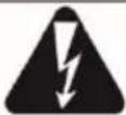 | Test voltage is present on terminals of the meter. | |
 | You must consult the manual. | |
 | The meter is ready for measurement. | |
 | This message displayed during or after the measurement indicates major noise in the system during the measurement. The measurement result may be affected by additional uncertainty. | |
| Un>50V (for DC voltage) or Un~>500V (for AC voltage) + continuous two-tone beep + red LED flashing | During the measurement, a voltage appeared or the object cannot be discharged for 30 seconds. After 5 seconds the meter returns to its default state - voltmeter. | |
 | Activation of current limit. The symbol displayed is accompanied by a continuous beep. | |
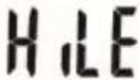 | Breakdown of the tested object insulation, the measurement is interrupted. The message appears after displaying LIMIT II for 20 s during the measurement, when voltage previously reached the nominal value. | |
 | Resistance compensation completed for test leads. | |
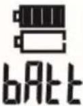 | Battery Status: Fully charged Battery discharged Battery discharged Charge battery. | |
SONEL S.A.
Wokulskiego 11
58-100 Świdnica
Poland
Customer Service
tel. +48 74 884 10 53
e-mail: customerservice@sonel.com
www.sonel.com
- USER MANUAL
- INSULATION RESISTANCE METERS
- INSULATION RESISTANCE METERS MIC-5010 • MIC-5005
- CONTENTS
- Safety
- Note:
- ATTENTION!
- Meter configuration
- Measurements
- Notes:
- WARNING:
- Measurement of insulation resistance
- Double-lead measurement
- Additional information displayed by the meter
- Three-lead measurement
- Measurements with increasing voltage - SV
- Dielectric Discharge Indicator – DD
- Low-voltage measurement of resistance
- Measurement of resistance of protective conductors and equipotential bonding with ±200 mA current
- Calibration of test leads
- Tightness test of MV cable jacket
- Memory of measurement results
- Storing the measurement results in the memory
- Viewing memory data
- Deleting memory data
- Deleting bank data
- Deleting the whole memory
- Data transmission
- Remarks:
- Set of accessories to connect the meter to a PC
- Data transmission through USB port
- Data transmission with Bluetooth module
- Firmware ≤1.30
- Firmware 1.31+
- Data transmission with OR-1 wireless module
- Software updates
- Power supply of the meter
- Monitoring the power supply voltage
- Battery power
- Charging rechargeable battery
- Mains power
- General principles for using Li-Ion rechargeable batteries
- General principles for using gel (lead) rechargeable batteries
- Cleaning and maintenance
- Storage
- Dismantling and utilisation
- Technical specifications
- Basic data
- Measurement of insulation resistance
- Measurement of leakage current
- Measurement of capacitance
- ±200 mA current
- Other technical data
- Additional data
- Additional uncertainties according to IEC 61557-2 (R _ISO )
- Additional uncertainties according to IEC 61557-4 (R
- Manufacturer
- SONEL S.A.
- WARNINGS AND GENERAL INFORMATION DISPLAYED BY THE METER
Brand : Sonel
Model : MIC-5010
Category : Measurement