
ZM1901 - Rowing Machine HMS Premium - Free user manual and instructions
Find the device manual for free ZM1901 HMS Premium in PDF.


| Product Type | Rowing Machine |
| Brand | HMS Premium |
| Model | ZM1901 |
| Resistance Type | Magnetic |
| Resistance Levels | 8 |
| Display | LCD Monitor |
| Display Functions | Time, Distance, Strokes, Calories, Pulse |
| Pulse Sensor | Hand Grip Pulse Sensors |
| Dimensions (L x W x H) | 200 x 50 x 50 cm |
| Weight | 30 kg |
| Maximum User Weight | 120 kg |
| Power Supply | 2 AAA Batteries (for monitor) |
| Frame Material | Steel |
| Seat | Ergonomic, Sliding |
| Foot Pedals | Adjustable with Straps |
| Transport Wheels | Yes |
| Foldable | Yes |
| Maintenance | Lubricate rail and chain monthly |
| Safety Features | Non-slip pedals, stable frame |
| Spare Parts Available | Yes, via manufacturer |
| Warranty | 2 years |
Frequently Asked Questions - ZM1901 HMS Premium
User questions about ZM1901 HMS Premium
0 question about this device. Answer the ones you know or ask your own.
Ask a new question about this device
Download the instructions for your Rowing Machine in PDF format for free! Find your manual ZM1901 - HMS Premium and take your electronic device back in hand. On this page are published all the documents necessary for the use of your device. ZM1901 by HMS Premium.
USER MANUAL ZM1901 HMS Premium
natural_image
Line drawing of a futuristic spacecraft with extended arm and visible propellers (no text or symbols)INSTRUKCJA UŻYTKOWANIA – MANUAL INSTRUCTION – NÁVOD K OBSLUZE- GEBRAUCHSANWEISUNG
ĆWICZENIA
Before using the equipment, read the precautions and directions contained in the following
instructions.
SAFETY PRECAUTIONS
- Read this manual carefully before first using and retain it for future reference.
- Observe all warnings and precautions including assembly steps. Use it only for intended purpose.
- Assemble and use it only according to this manual to assure your safety. Inform all other users about safe usage.
- Keep it away from children and pets. Don't let children unattended near this device. Only an adult person may assemble and use it.
- Ask your physician for advice before starting any exercise program. It is especially necessary if your suffer from some health problems or if you take some medication that could affect your heart rate, blood pressure or cholesterol level.
- Observe body signals. If you feel some problems (pain, tightness in chest, irregular heartbeat, breathing shortness, dizziness or nausea), stop immediately, improper exercising can result in serious health problems or in an injury.
- Put it only on a flat, dry and clean surface and keep a safety safety clearance of at least 0.6 m from other objects for higher safety. Use a protective cover to protect carpet or floor.
- Wear adequate sports clothes and sports shoes. Avoid too loose clothes.
- Don't use it outdoors.
- Check this device for damage or wearing before each using. Regularly check all bolts and nuts. They should be well tightened, Re-tighten, if necessary. Never use damaged or worn device to assure your safety.
- If some sharp edges occur, stop using.
- If you hear some unusual noises coming from this device, stop using.
- No adjustable part should protrude and obstruct user movements. Only one person may use it at time.
- Braking is independent of the speed.
- It is not intended for therapeutic purpose.
- Pay attention while lifting or transporting it to avoid back injury. Use only proper lifting techniques or ask some other person for help.
- Don't do any improper modification of this product. If necessary, contact authorized service.
- Max user weight: 120 kgs
- Category: The equipment has been tasted and certified according EN ISO 20957-1 under class HC. It is not suite for therapeutic use.
WARNING! The heart rate frequency monitoring may not be completely accurate. Overexertion during training can lead to a serious injury or even death. If you start to feel faint, stop the exercise immediately.
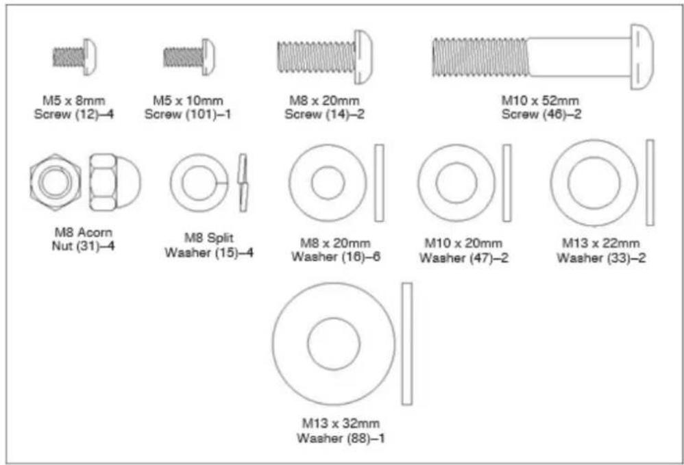
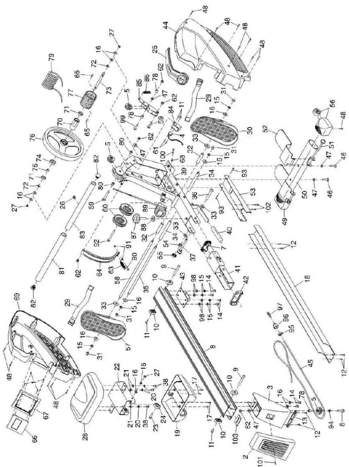
Part List
| Key No. | Qty. | Description | Key No. | Qty. | Description |
| 1 | 4 | M2.5 x 10mm Screw | 53 | 1 | Frame Cover |
| 2 | 1 | Rear Stabilizer Cover | 54 | 1 | 1/2" Locknut |
| 3 | 1 | Rear Stabilizer | 55 | 1 | Nut Cap |
| 4 | 1 | Reed Switch | 56 | 1 | Right Stabilizer Cap |
| 5 | 3 | Small Pulley | 57 | 1 | Left Pedal |
| 6 | 1 | M10 x 30mm Screw | 58 | 1 | Pedal Axle |
| 7 | 1 | Rail Bracket Cap | 59 | 2 | M10 x 48mm Screw |
| 8 | 1 | Rail | 60 | 2 | Large Pulley |
| 9 | 2 | M6 x 12mm Screw | 61 | 2 | M3 x 10mm Screw |
| 10 | 4 | Carriage Bumper | 62 | 5 | M10 Locknut |
| 11 | 4 | Frame Bushing | 63 | 1 | Magnet Spring |
| 12 | 6 | M5 x 8mm Screw | 64 | 1 | C-magnet |
| 13 | 1 | Rear Foot | 65 | 2 | M8 x 16mm Screw |
| 14 | 6 | M8 x 20mm Screw | 66 | 1 | Console |
| 15 | 12 | M8 Split Washer | 67 | 1 | Console Bezel |
| 16 | 14 | M8 x 20mm Washer | 68 | 1 | M5 x 12mm Washer |
| 17 | 4 | M4 x 12mm Screw | 69 | 1 | Left Shield |
| 18 | 1 | Rail Cover | 70 | 1 | Spool Bushing |
| 19 | 1 | Carriage Cover | 71 | 2 | 6001 Bearing |
| 20 | 6 | M6 Split Washer | 72 | 2 | C-clip |
| 21 | 6 | M6 Washer | 73 | 1 | Flywheel Axle |
| 22 | 1 | Seat Carriage | 74 | 1 | 6904 Bearing |
| 23 | 4 | M8 x 32mm Screw | 75 | 1 | Coaster Bearing |
| 24 | 4 | Roller | 76 | 1 | Flywheel |
| 25 | 1 | Shield Cover | 77 | 1 | Spool |
| 26 | 1 | Grommet | 78 | 3 | 6mm Bushing |
| 27 | 6 | M8 Locknut | 79 | 1 | Cord |
| 28 | 1 | Seat | 80 | 2 | 13.5mm Bushing |
| 29 | 2 | Pedal Strap | 81 | 1 | Foam Grip |
| 30 | 1 | Right Pedal | 82 | 2 | Row Bar Cap |
| 31 | 4 | M8 Acorn Nut | 83 | 1 | Row Bar |
| 32 | 2 | Pedal Spacer | 84 | 1 | Reed Switch Bracket |
| 33 | 4 | M13 x 22mm Washer | 85 | 1 | Tension Pulley Bracket |
| 34 | 2 | Pedal Stop | 86 | 1 | Tension Spring |
| 35 | 1 | Stop Rod | 87 | 1 | Frame Knob |
| 36 | 1 | 1/2" x 100mm Bolt | 88 | 1 | M13 x 32mm Washer |
| 37 | 1 | Frame Pin | 89 | 1 | Resistance Control |
| 38 | 6 | M6 x 16mm Screw | 90 | 1 | M5 x 35mm Screw |
| 39 | 1 | Frame | 91 | 2 | M5 Nut |
| 40 | 1 | Frame Foot | 92 | 1 | M10 x 68mm Screw |
| 41 | 1 | Rail Bracket | 93 | 2 | M4 x 8mm Screw |
| 42 | 1 | Rail Cap | 94 | 1 | M10 Washer |
| 43 | 1 | Rail Attachment Bracket | 95 | 1 | Bungee End |
| 44 | 1 | Right Shield | 96 | 1 | Bungee Cover |
| 45 | 1 | Bungee Cord | 97 | 1 | Bungee Clip |
| 46 | 2 | M10 x 52mm Screw | 98 | 4 | M8 Washer |
| 47 | 5 | M10 x 20mm Washer | 99 | 1 | M10 x 36mm Screw |
| 48 | 14 | M4 x 20mm Screw | 100 | 1 | M5 x 60mm Screw |
| 49 | 1 | Left Stabilizer Cap | 101 | 1 | M5 x 10mm Screw |
| 50 | 1 | Front Stabilizer | 102 | 2 | M4 x 12mm Machine Screw |
| 51 | 2 | Foot Plate Pin | 103 | 1 | Rail Plate |
| 52 | 2 | Foot Plate | * | - | User's Manual |
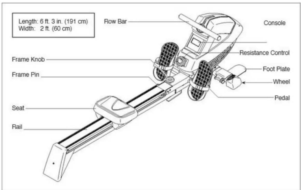
TECHNICAL INFO
Item size: 191cm x 60cm x 51cm
NW: 33kg
GW: 36,5kg
Max load: 120k
Note: Specifications are subject to change without notice. For information about ordering replacement parts, see the back cover of this manual. *These parts are not illustrated.
Part chart
Assembly:
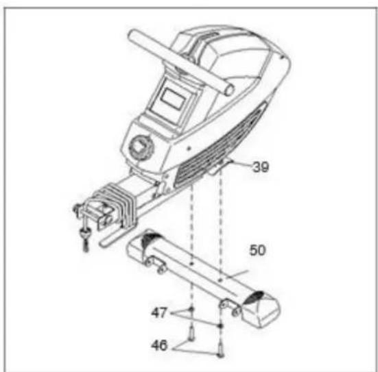
1) Orient the Front Stabilizer (50) as shown. Attach the Front Stabilizer (50) to the Frame (39) with two M10 x 52mm Screws (46) and two M10x 20mm Washers (47).
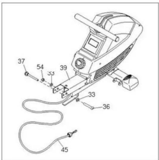
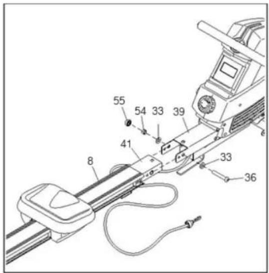
2) Remove the Frame Pin (37) from the Frame (39). Next, unwrap the Bungee Cord (45) from the Frame (39). Then, remove the 1/2" Locknut (54), the two M13x 22mm Washers (33), and the 1/2" x 100mm Bolt (36) from the Frame (39). Note: The parts that you removed will be used in steps 4 and 5.
3) Orient the Rail (8) as shown Attach the Rail Bracket (41) to the Frame (39) with the 1/2" x 100mm Bolt (36), the two M13 x22mm Washers (33), and the 1/2" Locknut (54) that you removed in step 3.
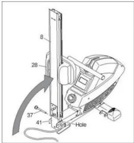
4) Move the Seat (28) to the front of the Rail (8). Have a second person raise the Rail (8) to the vertical position. Fully insert the Frame Pin (37) into the indicated hole in the Rail Bracket (41) so that it holds the Rail in place.
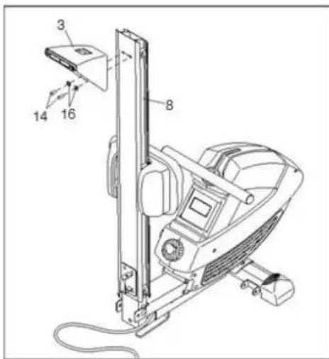
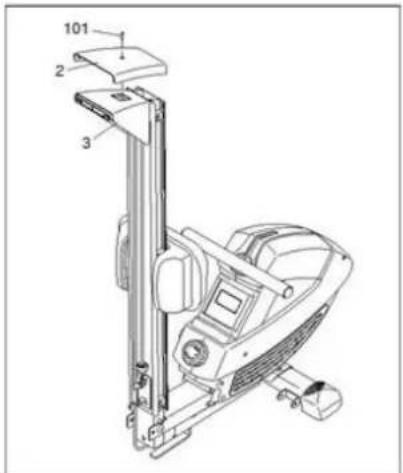
5) Attach the Rear Stabilizer (3) to the Rail (8) with two M8 x 20mm Screws (14) and two M8 x20mm Washers (16).
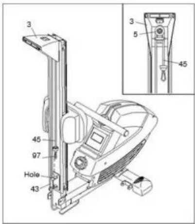
6) See the inset drawing. Route the end of the Bungee Cord (45) around the Small Pulley (5) on the Rear Stabilizer (3) as shown. Make sure that the Bungee Cord (45) is not twisted. Attach the Bungee Clip (97) to the indi- cated hole in the Rail Attachment Bracket (43).
7) Attach the Rear Stabilizer Cover (2) to the Rear Stabilizer (3) with an M5 x 10mm Screw (101).
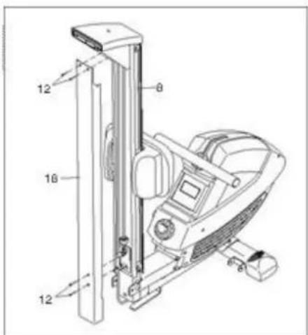
8) Orient the Rail Cover (18) as shown. Attach the Rail Cover (18) to the Rail (8) with four M5 x 8mm Screws (12).
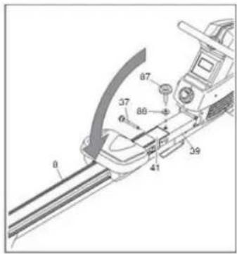
9) Remove the Frame Pin (37) from the Rail Bracket (41), and lower the Rail (8) to the floor. Next, insert the Frame Pin (37) into the Frame
(39) and into the Rail Bracket (41). Then, slide an M13 x 32mm Washer (88) onto the Frame Knob (87), insert the Frame Knob into the Frame (39), and tighten the Frame Knob into the Rail Bracket (41)
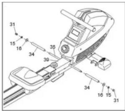
10) Identify the Stop Rod (35), which is slightly shorter than the Pedal Axle (not shown).
Insert the Stop Rod (35) into the Frame (39) and center it. Next, slide a Pedal Stop (34), an M8 x 20mm Washer (16), and an M8 Split Washer (15) onto each side of the Stop Rod (35). Then, tighten an M8 Acorn Nut (31) onto each end of the Stop Rod (35) at the same time.
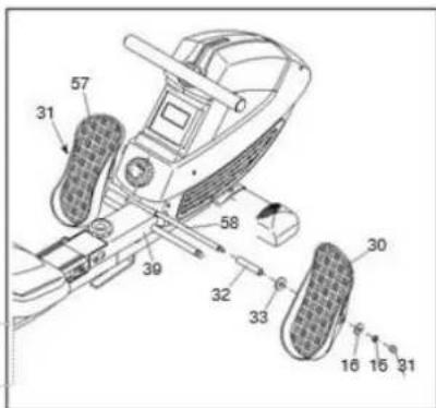
11) Insert the Pedal Axle (58) into the welded tube on the Frame (39) and center it. Next, slide a Pedal Spacer (32) and an M13 x22mm Washer (33) onto each side of the Pedal Axle (58) (only one side is shown). Next, identify the Right Pedal (30) and the Left Pedal (57). Slide the Right Pedal onto the right side of the Pedal Axle (58), and slide the Left Pedal onto the left side of the Pedal Axle. Next, slide an M8 x 20mm Washer (16) and an M8 Split Washer (15) onto each side of the Pedal Axle (58) (only one side is shown). Then, tighten an M8 Acorn Nut (31) onto each end of the Pedal Axle (58).
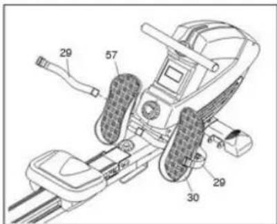
12) Insert a Pedal Strap (29) through the Right Pedal (30) as shown. Then, route the end of the Pedal Strap through the buckle on the Pedal Strap. Attach the other Pedal Strap (29) to the Left Pedal (57) in the same way.
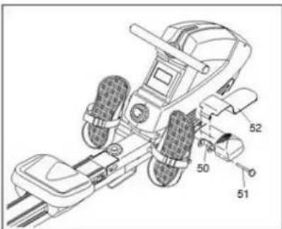
13) Attach a Foot Plate (52) to one side of the Front Stabilizer (50) with a Foot Plate Pin (51). Attach the other Foot Plate (not shown) to the other side of the Front Stabilizer (50) in the same way.
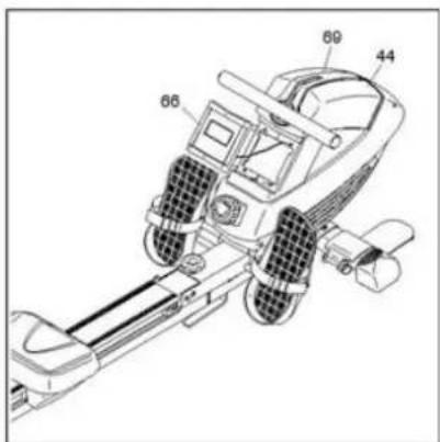
Console into the Shields.
14) The Console (66) requires two AA batteries (not included); alkaline batteries are recommended. Do not use old and new batteries together or alkaline, standard, and rechargeable batteries together. IMPORTANT: If the Console has been exposed to cold temperatures, allow it to warm to room temperature before you insert batteries. Otherwise, you may dam- age the console display or other electronic components. Carefully pry the Console (66) out of the Shields (44, 69); be careful not to pull on the wire attached to the Console. Next, remove the screw (not shown) and the battery cover from the back of the Console. Insert batteries into the battery compartment; make sure to orient the batteries as shown by the diagram inside the battery compartment. Then, reattach the battery cover with the screw, and press the
15) Make sure that all parts are properly tightened before you use the rower. Extra parts may be included. Place a mat under the rower to protect the floor.
HOW TO ADJUST THE RESISTANCE
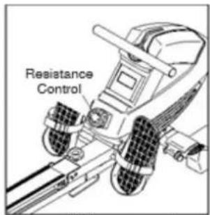
To vary the intensity of your exercise, you can adjust the resistance that you feel when you pull the row bar. To increase the resistance, turn the resistance control clockwise; to decrease the resistance, turn the resistance control counterclockwise. IMPORTAN resistance control, stop turning it when turning becomes difficult.
HOW TO MOVE THE ROWER
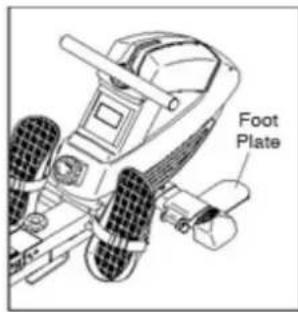
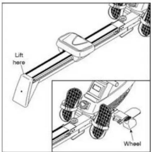
Stand behind the rower and lift the rear stabilizer until the rower will roll on the wheels. Then, carefully move the rower to the desired location, and lower it to the floor.
HOW TO FOLD AND STORE THE ROWER
The rower can be stored in a folded position to conserve space. Store the rower in a location where children cannot tip it. Remove the batteries from the console when storing the rower for extended periods of time.
Remove the Frame Knob (87) and the M13x 32mm Washer (88). Next, remove the Frame Pin (37). Keep the Frame Knob and the Washer in a place where they will not become lost. Raise the Rail (8) to the vertical position.
Then, fully insert the Frame Pin (37) into the Rail Bracket (41) so that it holds the Rail in place.
HOW TO UNFOLD THE ROWER
Remove the Frame Pin (37), and lower the Rail (8) to the floor. Next, insert the Frame Pin into the Frame (39) and into the Rail Bracket (41). Then, tighten the Frame Knob (87) and the M13 x 32mm Washer (88) into the Frame and into the Rail Bracket.
COMPUTER
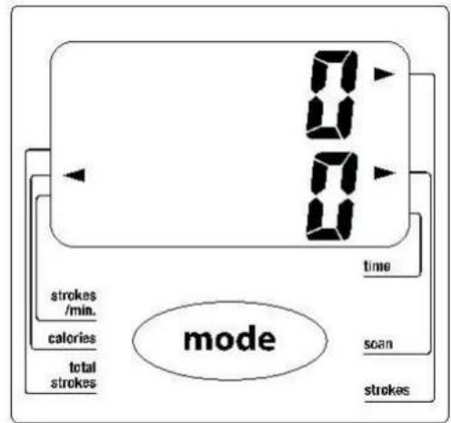
Strokes/Min.—This shows the number of rowing strokes you are completing per minute.
Calories—This mode shows the approximate number of calories you have burned during your workout.
Total Strokes—This mode shows the total number of rowing strokes you have completed since the console was last reset. Note: To reset the console, remove the batteries from the console and then reinsert them.
Time—This mode shows the elapsed time.
Scan—This mode shows the time, strokes, total strokes, calories, and strokes per minute modes, for a few seconds each, in a repeating cycle.
Strokes—This mode shows the number of rowing strokes you have completed during your workout.
HOW TO USE THE CONSOLE
-
Turn on the console. To turn on the console, press the Mode button on the console or simply begin rowing.
-
Select one of the display modes. Scan mode—To select the scan mode, press the Mode button repeatedly until an arrow appears next to the Scan label.
Strokes per minute, calories, total strokes, time, or strokes—To select one of these modes for continuous display, press the Mode button repeatedly until an arrow appears next to the label for the desired mode. Make sure that an arrow does not appear next to the Scan label.
-
Begin rowing and follow your progress with the display. To reset the display to zero, press and hold the Mode button for several seconds.
-
When you are finished exercising, the console will turn off automatically. If the row bar does not move for a few seconds, the console will pause.
The console has an auto-off feature. If the row bar does not move and the Mode button is not pressed for a few minutes, the power will turn off automatically to save the batteries.
MAINTENANCE AND TROUBLESHOOTING
Maintenance
Inspect and tighten all parts of the rower regularly.. Replace any worn parts immediately.
To clean the rower, use a damp cloth and a small. amount of mild detergent. IMPORTANT: To avoid damage to the console, keep liquids away from the console and keep the console out of direct sunlight.
Pedal greasing
If the pedals squeak when you use the rower. Remove the Right and Left Pedals (30, 57), and apply a small amount of the included grease to both sides of the Pedal Axle (58). Then, reattach the Pedals.
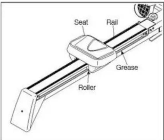
Roller greasing: If the rollers beneath the seat squeak when you use the rower, apply a small amount of the included grease to a paper towel, and spread a thin layer evenly along the rail where the rollers move. Then, wipe off any excess grease.
EXERCISE GUIDE
Rowing is an extremely effective form of exercising. It strengthens your heart and improves blood circulation as well. There are involved all major muscle groups of back, waist, arms, shoulders, hips and legs.
1. Basic rowing stroke
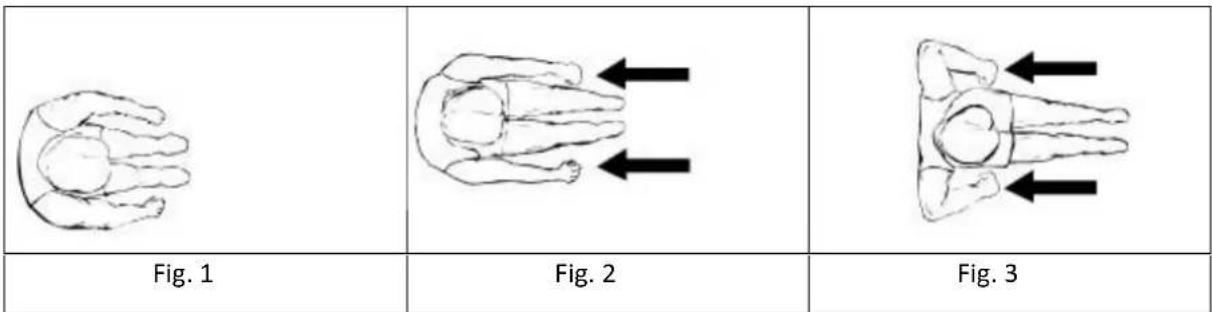
Sit on the saddle and fasten your feet to the pedals using Velcro straps. Then take hold of the rowing bar. Take the start position, lean forward with your arms straight and knees bent as shown in Fig. 1. Push your body backwards while simultaneously straightening your back and legs (Fig. 2). Continue this movement until you are leaning slightly backwards. Bring your arms out of the side during this phase (Fig. 3). Thereafter return to the second position and repeat it as shown below.
2. Training time
Rowing is a strenuous training style. Because of it, is better to start with a short and easy program and continue to a longer and intensive workout. Start rowing for about 5 minutes and increase the workout length gradually to improve your fitness. Finally, you should be able to row for 15-20 mins. Don't try to do it too quickly. Try to train on alternate days, 3 times a week. Take a recovery time between workouts.
3. Rowing style alternation
ONLY ARM ROWING: This workout should tone your arm, shoulder, back and abdominal muscles. Sit on the machine as shown in Fig. 4. Straight your legs, lean forward and grasp the handles. Control your moving and gradually lean back to just past the up-right position (Fig. 5) and continue to pull the
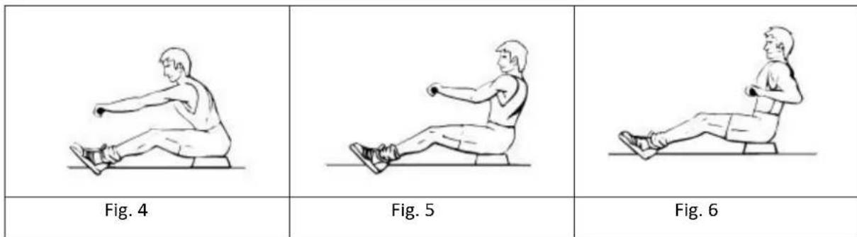
handles towards your chest (Fig. 6). Return to the starting position and repeat.
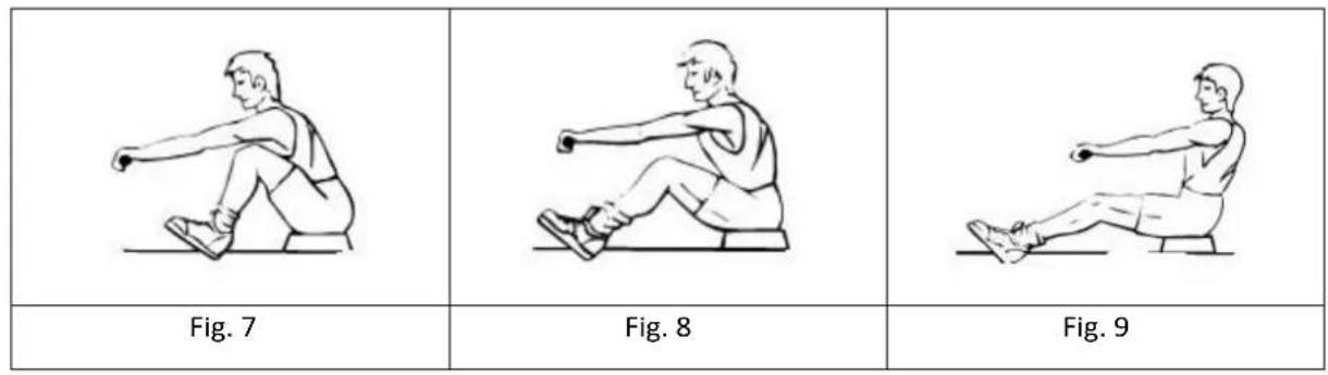
ONLY LEG ROWING: This workout helps toning your leg and back muscles. Keep your back straight and arms out-stretched, bend your legs until you will grasp the rowing handles in the starting position (Fig. 7). Use your legs to push your body back (Fig. 8) while keeping your arms and back straight as shown in Fig. 9.
4. Exercise instructions
Using this device provides you with several benefits such as better physical fitness, toned muscles and, in combination with controlled diet, weight loss.
I. WARM-UP PHASE
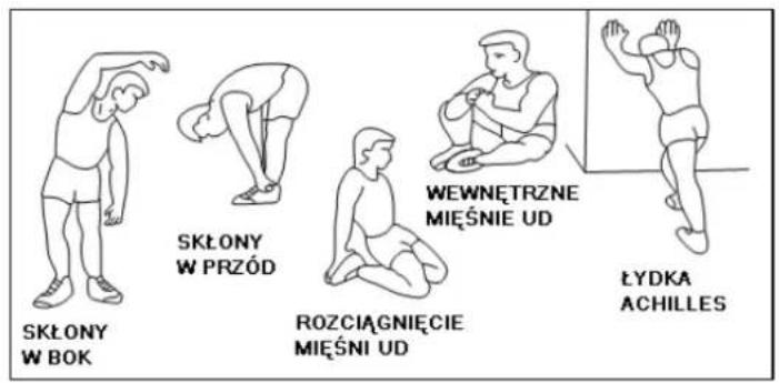
This phase should help improving blood circulation and make your muscles working properly while reducing a cramp risk or injury. It is advisable to do a few stretching exercises as shown below. Each stretching exercise should be taken for approx. 30 seconds. Don't overstretch and don't jerk your muscles. If you feel pain, stop immediately.
II. EXERCISE PHASE
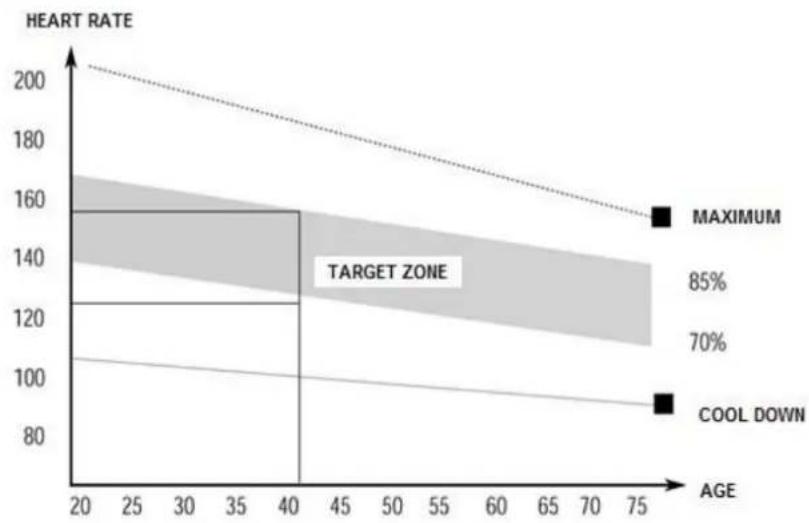
It is a phase, during which you should put in your effort. After regular workout, your leg muscles should get more flexible. Keep steady tempo throughout your exercising. The workout intensity should be sufficient to raise your heartbeat into the target zone as shown below.
NOTE: This stage should last for at least 12 mins. Thus, most people start at approx. 15-20 mins.
line
| AGE | HEART RATE | | --- | --- | | 20 | 160 | | 40 | 160 | | 75 | 90 |III. COOL-DOWN PHASE
In this stage, your cardio-vascular system and muscles should get calm. Repeat the warm-up exercises, reduce your tempo and continue for approx. 5 mins. Repeat the stretching exercises, but don't overstretch or jerk your muscles. As you get fitter, you can exercise longer and harder. It is advisable to train at least three times a week and, if possible, to space your workouts evenly throughout a week.
BEZPEČNOSTNÍ POKYNY
REGULACE ZÁTĚŽE
CVIČENÍ PŘÍTAHŮ
PRŮVODCE CVIKY
line
| AGE | HEART RATE | | --- | --- | | 20 | 160 | | 40 | 120 | | 75 | 90 |III. FÁZE PROTAHOVÁNÍ PO TRÉNINKU
Schritt 12.
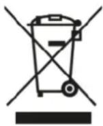
EN: Marking the equipment with a symbol of a crossed-out waste container informs about prohibition of placing used electrical and electronic equipment with other household waste. According to the WEEE Directive on used electrical and electronic waste management, separate disposal methods must be applied for this type of equipment. A user, who intends to dispose this product, is required to deliver it to a collection point for used electrical and electronic equipment in order to contribute to reuse, recycling, or recovery and consequently, to protect the environment. To do this, contact the point where the device was purchased or local government officials. Hazardous components contained in the electronic equipment can cause long-lasting adverse changes in the environment, as well as have a harmful effect on human health.
-
The Seller provides guarantee on behalf of the Guarantor within the territory of the Republic of Poland for the period of 24 months from the date of sale: electric power assisted booster 24 months, charger 6 months.
-
The Guarantee will be recognised by the shop or service centre after the client provides:
- clearly and correctly filled-in guarantee card with the sale stamp and the seller's signature
- valid purchase confirmation for the equipment including the date of sale / bill, complained product.
-
Possible defects and damages revealed during the guarantee period shall be remedied free of charge within not more than 21 days from the delivery of the product to the shop or service.
-
Should it be necessary to import some components, the guarantee term can be extended by the period required to import such part, however such period shall not be longer than 90 days.
-
The guarantee does not cover:
- mechanical damages and subsequent defects,
- damages and defects resulting from incorrect storage and usage of the equipment against its purpose,
- incorrect assembly and maintenance,
- damages and consumption of such elements as: cables, straps, rubber parts, pedals, sponge grips, wheels, bearings, etc.
- The guarantee expires in the event of:
- expiry of the validity term,
- self-repairs,
- failure to follow the rules of correct operation.
-
The product handed over for repair should be complete and clean. If some parts are missing, the service is entitled to refuse to accept the product for repair. The service may refuse to accept a dirty product or clean in on the client's expense after the client's written permit.
-
The guarantee does not cover activities related to assembly, maintenance, which, according to the instruction, the user is obliged to perform themselves.
-
The Guarantor also informs that they offer post-guarantee service.
-
The product should be provided in its original packaging and should be secured for shipment.
-
To exercise the guarantee follow the procedure posted on the website: https://serwis.abisal.pl/
In case of non-conformity of the sold thing with the contract, the buyer is entitled by law to legal remedies from and at the expense of the seller. The guarantee does not affect such remedies.
THE EQUIPMENT IS NOT INTENDED FOR REHABILITATION AND THERAPY
NOTES ON THE COURSE OF REPAIRS
| Item | Date of notificacion | Date of provision | Course of repairs | Signature of the recipient (shop, owner) |
GARANTIEKARTE
Artikelname:
EAN-Code:
HMS-FITNESS.COM

IMPORTER: ABISAL SP. Z O.O., ul. Pyskowicka 17, 41-807 Zabrze, Polska
DISTRIBUTOR: ABISTORE SPORT S.R.O, U Cihelny 230/3, 74801 Hlučín, Česká Republika
abisal@abisal.pl www.abisal.pl


- ĆWICZENIA
- SAFETY PRECAUTIONS
- TECHNICAL INFO
- Assembly:
- HOW TO ADJUST THE RESISTANCE
- HOW TO MOVE THE ROWER
- HOW TO FOLD AND STORE THE ROWER
- HOW TO UNFOLD THE ROWER
- COMPUTER
- HOW TO USE THE CONSOLE
- MAINTENANCE AND TROUBLESHOOTING
- Maintenance
- Pedal greasing
- EXERCISE GUIDE
- Basic rowing stroke
- Training time
- Rowing style alternation
- Exercise instructions
- WARM-UP PHASE
- EXERCISE PHASE
- COOL-DOWN PHASE
- BEZPEČNOSTNÍ POKYNY
- REGULACE ZÁTĚŽE
- CVIČENÍ PŘÍTAHŮ
- PRŮVODCE CVIKY
- FÁZE PROTAHOVÁNÍ PO TRÉNINKU
- Schritt 12.
- THE EQUIPMENT IS NOT INTENDED FOR REHABILITATION AND THERAPY
- GARANTIEKARTE
Brand : HMS Premium
Model : ZM1901
Category : Rowing Machine