
ZM1801 - Rowing Machine HMS Premium - Free user manual and instructions
Find the device manual for free ZM1801 HMS Premium in PDF.


| Product Type | Rowing Machine |
| Brand | HMS Premium |
| Model | ZM1801 |
| Dimensions (L x W x H) | 191 x 60 x 49 cm |
| Net Weight | 38.5 kg |
| Maximum User Weight | 120 kg |
| Resistance Type | Magnetic, 8 levels |
| Monitor Functions | Count, Time, Calories, RPM, Pulse (with optional belt), Scan |
| Power Supply | 2 x AAA batteries (not included) |
| Frame Material | Steel with aluminum sliding tube |
| Seat | Adjustable saddle on aluminum track |
| Pedals | Adjustable with straps |
| Handlebar | Fixed with foam grip |
| Transportation Wheels | Yes, front wheels for easy moving |
| Foldable | Yes, aluminum track folds for storage |
| Certification | EN ISO 20957-1 Class H (home use) |
| Safety Features | Free area of 0.6 m around equipment, emergency dismount, pre-use inspection required |
| Maintenance | Wipe clean after use, check tightness of bolts and condition of bands regularly |
| Assembly Required | Yes, with included parts and tools (see manual) |
Frequently Asked Questions - ZM1801 HMS Premium
User questions about ZM1801 HMS Premium
0 question about this device. Answer the ones you know or ask your own.
Ask a new question about this device
Download the instructions for your Rowing Machine in PDF format for free! Find your manual ZM1801 - HMS Premium and take your electronic device back in hand. On this page are published all the documents necessary for the use of your device. ZM1801 by HMS Premium.
USER MANUAL ZM1801 HMS Premium
natural_image
Technical line drawing of a stationary exercise machine (no text or symbols present)INSTRUKCJA UŻYTKOWANIA – MANUAL INSTRUCTION - NÁVOD K OBSLUZE
2. MONTAŻ ALUMINIOWEJ PROWADNICY
3. MONTAŻ TYLNEGO STABILIZATORA
natural_image
Close-up of a mechanical component with parallel lines, no visible text or symbols4. MONTAŻ SIEDZENIA
5. MONTAŻ OSŁONY TYLNEGO STABILIZATORA
natural_image
Technical line drawing of a mechanical device with exploded view and internal components (no text or symbols)6. MONTAŻ DOLNEJ OSŁONY PROWADNICY.
8. MONTAŻ PEDALÓW.
9. MONTAŻ PRZEDNIEGO SŁUPA
natural_image
Technical line drawing of a stationary exercise machine with labeled components (no text or symbols present)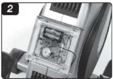
natural_image
Interior view of a mechanical device showing internal components and wiring (no visible text or symbols)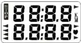
FUNKCJE
natural_image
Person performing a row exercise on a stationary bar (no text or symbols visible)IMPORTANT SAFETY INFORMATION
This product has been designed for home use only and built for optimum safety. Please note the following safety precautions:
-
Before starting any exercise program you should consult your doctor to determine if you have any physical or health conditions that could create a risk to your health and safety, or prevent you from using the equipment properly. Your doctor's advice is essential if you are taking medication that affects your heart rate, blood pressure or cholesterol level. This is especially important for persons over the age of 35, pregnant women, or those with pre-existing health problems or balance impairments.
-
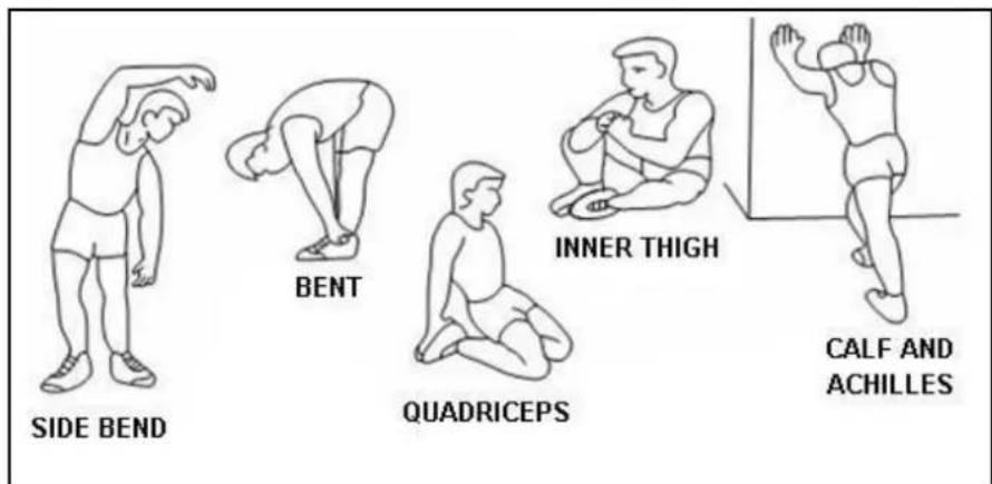
Before using this equipment to exercise, always do stretching exercises to properly warm up.
-
Be aware of your body's signals. Incorrect or excessive exercise can damage your health. Stop exercising if you experience any of the following symptoms: pain, tightness in your chest, irregular heartbeat, extreme shortness of breath, feeling light headed, dizzy or nauseous. If you do experience any of these conditions you should consult your doctor before continuing with exercise program. Injuries to health may result from incorrect or excessive training.
-
During exercises and after keep children and pets away from the equipment.
-
Use the equipment on a stable and levelled surface with a protective cover for your floor or carpet. Move all sharp objects.
-
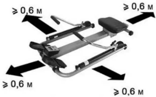
Free area shall be not less than 0,6 m greater than the training area in the directions from which the equipment is accessed. Free area must also include the area for emergency dismount. Where equipment is positioned adjacent to each other the value of the free area may be shared.
-
Before each use, visually inspect the unit including hardware and resistance bends.
-
Before using the equipment, check if the nuts, bolts and other bends are securely tightened.
-
Always use the equipment as indicated. If you find any defective components whilst assembling or checking the equipment, or if you hear any unusual noise coming from the equipment while using, stop. Do not use the equipment until the problem has been rectified.
-
Do not insert any object into any openings.
-
Be aware of all regulation and constructions parts which may disturb during exercises.
-
The safety level of the equipment can only be maintained if it is regularly examined for damage and/or wear and tear.
-
Wear suitable clothing whilst using the equipment. Avoid wearing loose clothing which may get caught in the equipment or that may restrict or prevent movement.
-
The equipment has been tested and certified according to EN ISO 20957-1 under class H. It is not suitable for therapeutic use.
-
Care must be taken when lifting or moving the equipment so as not to injure your back. Always use proper lifting techniques and/or use assistance. The rowing machine is equipped with transportation wheels helping in moving the product to desired place. Store in dry place.
-
The equipment is designed for adult use only. Keep unsupervised children away from the equipment.
-
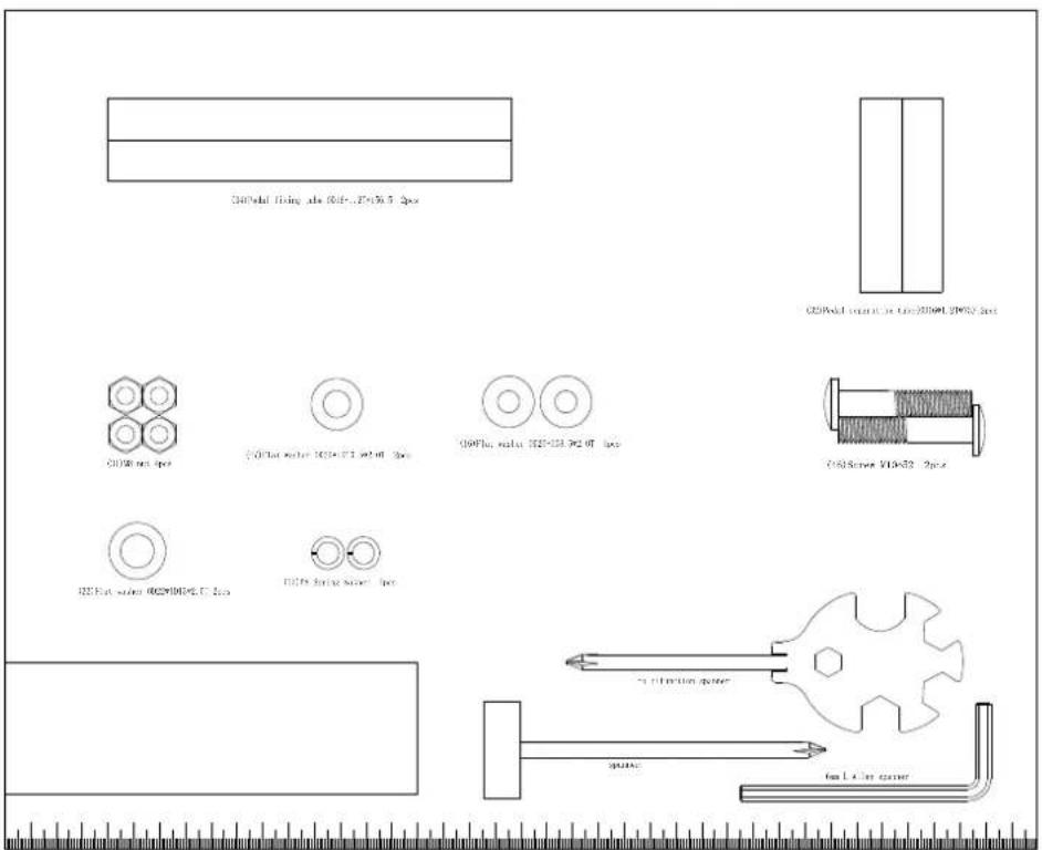
Assemble this unit as described in this manual. Use only parts from the set. Check all parts with the part list.
WARNING: READ ALL INSTRUCTIONS BEFORE USING ANY FITNESS EQUIPMENT. WE ASSUME NO RESPONSIBILITY FOR PERSONAL INJURY OR PROPERTY DAMAGE CAUSED BY OR THROUGH THE USE OF THIS PRODUCT
SPECIFICATIONS
Weight - 38.5 kg
Dimensions - 191*60*49 cm
Maximum weight of user - 120 kg
MAINTENANCE
Your unit has been carefully designed to require minimum maintenance. To ensure this, we recommend that you do the following:
- Keep your unit clean by wiping sweat, dust or other residue off with a soft, clean cloth after each use
• Always make sure that the bands are secure and show no signs of wear
• Regularly check the tightness of nuts and bolts
TENSION ADJUSTMENT
Turn the tension control (magnetic, 1 - 8) knob anti-clockwise to reduce the tension, turn the tension control knob clockwise to increase the tension.
| part | Name and description | Qty. | part | Name and description | Qty. |
| 1 | Screw M2.5*10 | 4 | 52 | Front stand | 2 |
| 2 | Rear stabilizer cover | 1 | 53 | Main frame bottom cover | 1 |
| 3 | Rear stabilizer | 1 | 54 | 1/2-13UNC*8T nylon cap | 1 |
| 4 | Sensor | 1 | 55 | Nylon cap | 1 |
| 5 | Roller 1 (Φ45) | 3 | 56 | front moving wheel (R) | 1 |
| 6 | Screw M5*10 | 1 | 57 | Left pedal | 1 |
| 7 | Aluminum sliding tube fixer | 1 | 58 | Pedal axle | 1 |
| 8 | Aluminum sliding tube | 1 | 59 | Screw M10*48 | 2 |
| 9 | Screw M6*1.0*12 | 2 | 60 | Roller 2 | 2 |
| 10 | Seat block | 4 | 61 | Screw M3*10 | 2 |
| 11 | Screw M6*10 | 4 | 62 | M10 nylon cap | 5 |
| 12 | Screw M5*8 | 2 | 63 | Magnet Spring | 1 |
| 13 | Rear stabilizer rubber stand | 1 | 64 | Magnet | 1 |
| 14 | Screw M8*20 | 6 | 65 | Screw M8*16 | 2 |
| 15 | M8 spring washer | 12 | 66 | Computer | 1 |
| 16 | Flat washer OD20*ID8.5*2.0T | 14 | 67 | Meter bracket | 1 |
| 17 | Screw M4*12 | 4 | 68 | ||
| 18 | Sliding tube bottom cover | 1 | 69 | Left chain cover | 1 |
| 19 | Seat bottom socket | 1 | 70 | Small belt roller | 1 |
| 20 | M6spring washer | 6 | 71 | 6001bearing | 2 |
| 21 | Flat washer OD16*ID6.5*1.5T | 6 | 72 | C style Button | 2 |
| 22 | Seat fixer | 1 | 73 | Flywheel axle | 1 |
| 23 | Screw M8*32 | 4 | 74 | 6904 bearing | 1 |
| 24 | Roller | 4 | 75 | HF2016 one way bearing | 1 |
| 25 | Screw M5*10 | 1 | 76 | Flywheel | 1 |
| 26 | Screw M4*10 | 4 | 77 | Small belt cover coat | 1 |
| 27 | M8 nylon cap | 6 | 78 | OD14*ID10*6 bushing | 3 |
| 28 | Saddle | 1 | 79 | Spring rope | 1 |
| 29 | Pedal belt | 2 | 80 | OD14*ID10*13.5 bushing | 2 |
| 30 | Right pedal | 1 | 81 | Handle bar foam | 1 |
| 31 | M8 nut | 4 | 82 | Handle bar end cap | 2 |
| 32 | Pedal separating tube(OD16*1.2T*75) | 2 | 83 | Handle bar | 1 |
| 33 | Flat washer OD22*ID13*2.0T | 4 | 84 | Magnetic sensor fixer | 1 |
| 34 | Pedal fixing tube OD16*1.2T*156.5 | 2 | 85 | Magnet fixer | 1 |
| 35 | Pedal fixing axle | 1 | 86 | Spring Φ1.0*16*75 | 1 |
| 36 | Screw 1/2*100 | 1 | 87 | Knob M12 | 1 |
| 37 | Pull pin | 1 | 88 | Flat washer OD32*ID13.5*2.0T | 1 |
| 38 | Screw M6*16 | 6 | 89 | TCD | 1 |
| 39 | Main frame | 1 | 90 | Screw M5*35 | 1 |
| 40 | Main frame support rubber shield | 1 | 91 | M5 nut | 2 |
| 41 | Sliding tube connector | 1 | 92 | Screw M10*68 | 1 |
| 42 | Sliding tube end cover | 1 | 93 | Screw M4*8 | 2 |
| 43 | Connector fixer | 1 | 94 | Flat washer OD14*ID10.5*1.5T | 1 |
| 44 | Right chain cover | 1 | 95 | Bounce rope end fixer | 1 |
| 45 | Bounce rope | 1 | 96 | Bounce rope cover | 1 |
| 46 | Screw M10*52 | 2 | 97 | Bounce rope end hook | 1 |
| 47 | Flat washer OD20*ID10.5*2.0T | 4 | 98 | Flat washer OD16*ID8.5*1.5T | 4 |
| 48 | Screw M4*20 | 13 | 99 | Screw M10*36 | 1 |
| 49 | front moving wheel (L) | 1 | 100 | Screw M5*60 | 1 |
| 50 | Front stabilizer | 1 | 101 | Flat washer OD12*ID5.5*1.0T | 1 |
| 51 | Lock pin | 2 |
ASSEMBLY INSTRUCTIONS
1. Assembly for stabilizer
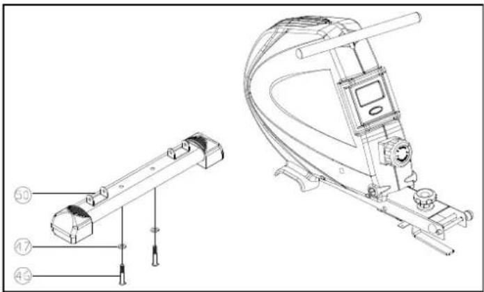
Attach the front stabilizer (50) to the main frame and lock them Up with screw M10*52(46) and flat washerOD20*ID10.5*2.0T(47)
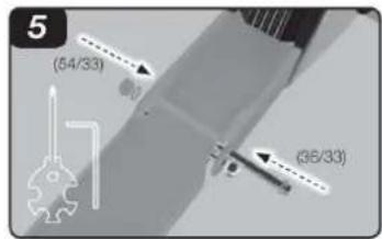
2. Assembly for Aluminum track
-
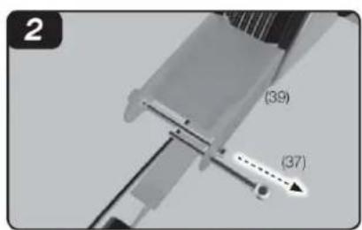
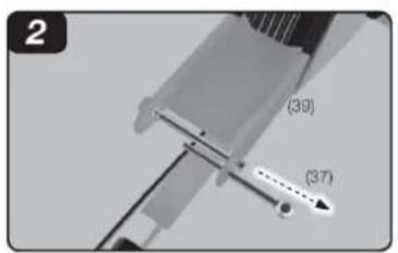
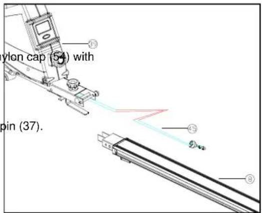
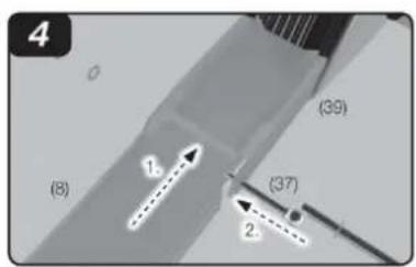
you can see aluminum sliding tube (8) mainframe (39) bounce rope (45)
-
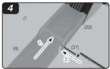
Remove the pull pin (37).
-
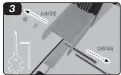
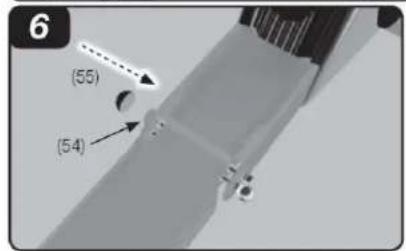
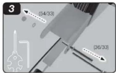
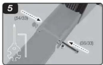
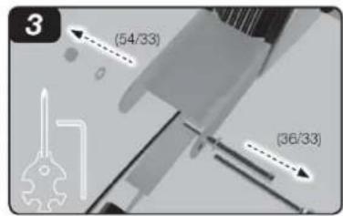
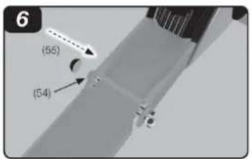
Remove the screw 1/2*100 (36), flat washer OD22*ID13*2.0T (33) and nylon cap (54) with spanner
-
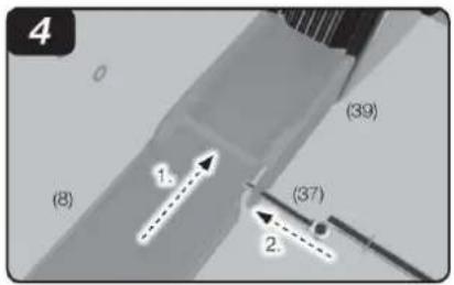
Attach the aluminum sliding tube (8) to the main frame (39) insert the pull pin (37).
-
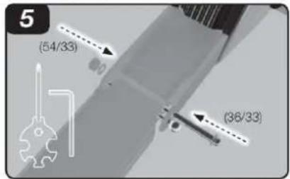
Look the removed screw 1.0*100(36). flat washer OD22*ID13*2.0T (33) and nylon cap(54)
-
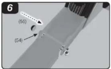
Cover the nylon cap (55) on the nylon cap 1/2-13UNC*8T (54).
Remove the pull pin (37), fold the aluminum sliding tube (8). Insert the pull pin (37).
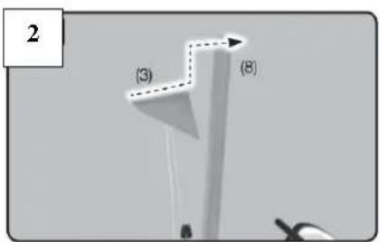
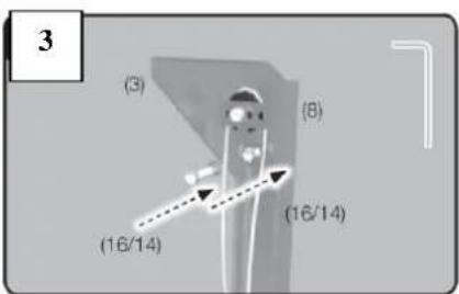
3. Assembly for rear stabilizer
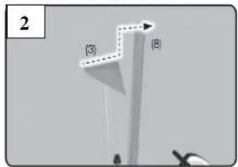
- first put the bounce rope round with right direct
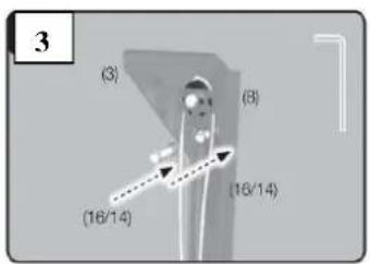
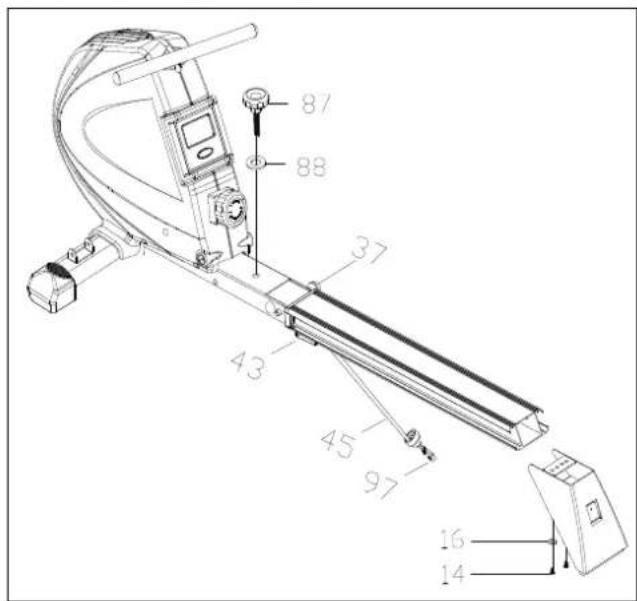
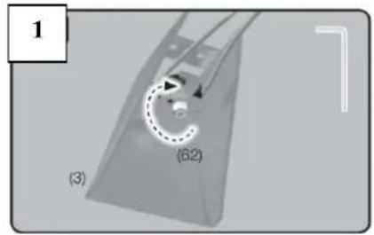
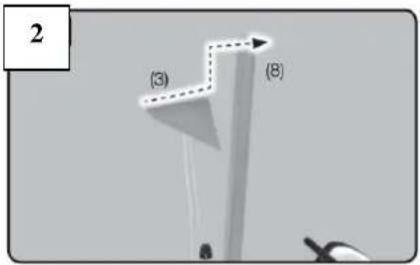
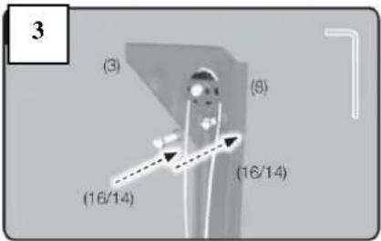
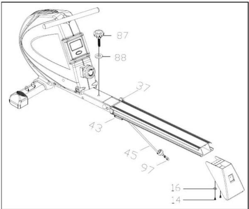
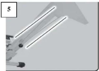
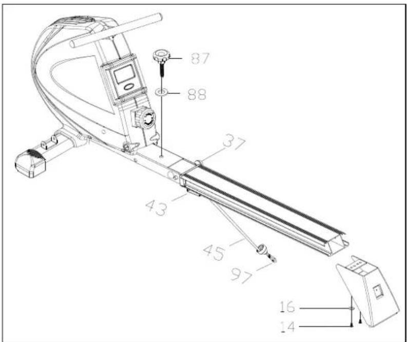
2-3. .attached rear stabilizer to the end of aluminum sliding tube lock with the screw M8*20(14) and flat washer OD20*ID8.5*1.5T(16) loosen knob (87) flat washer(88),move the pull pin(37) to make the aluminum sliding to the floor then make the knob(87) through flat washer(88) and lock them ,insert the pull pin(37) at last
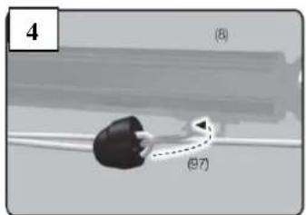
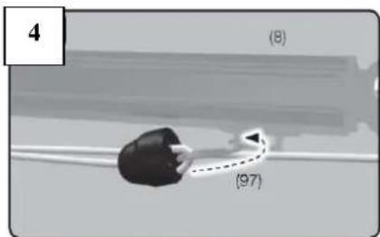
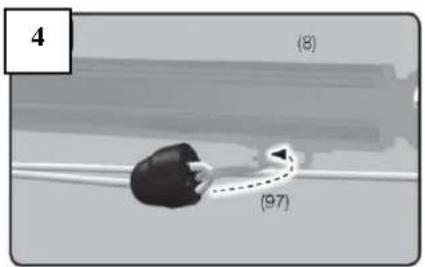
4.Fastness the Bounce rope end hook(97)
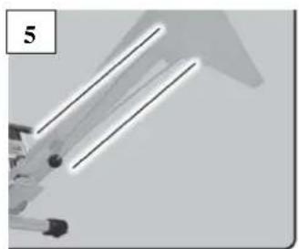
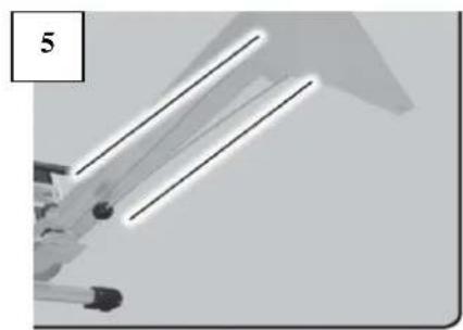
【NOTICE: in this step process :the bounce rope round the pulley which on the rear stabilizer to keep parallel Do not cross.】
natural_image
Close-up of a mechanical component with parallel lines and a numbered label '5' (no readable text or symbols)4. Assembly for seat
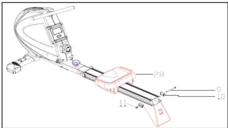
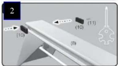
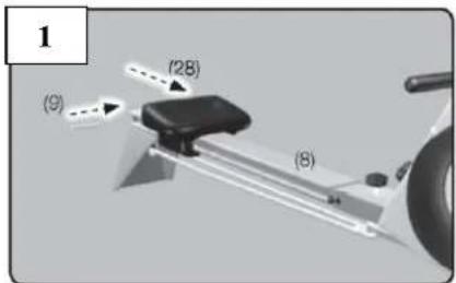
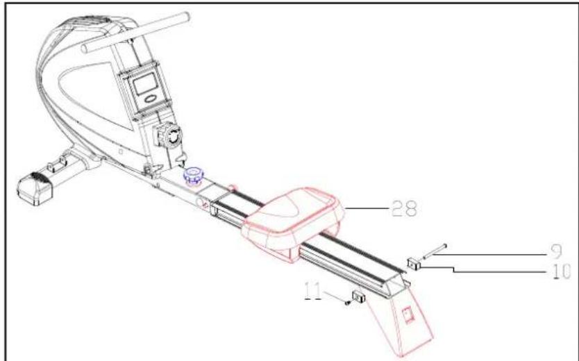
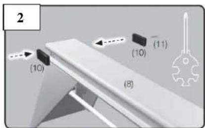
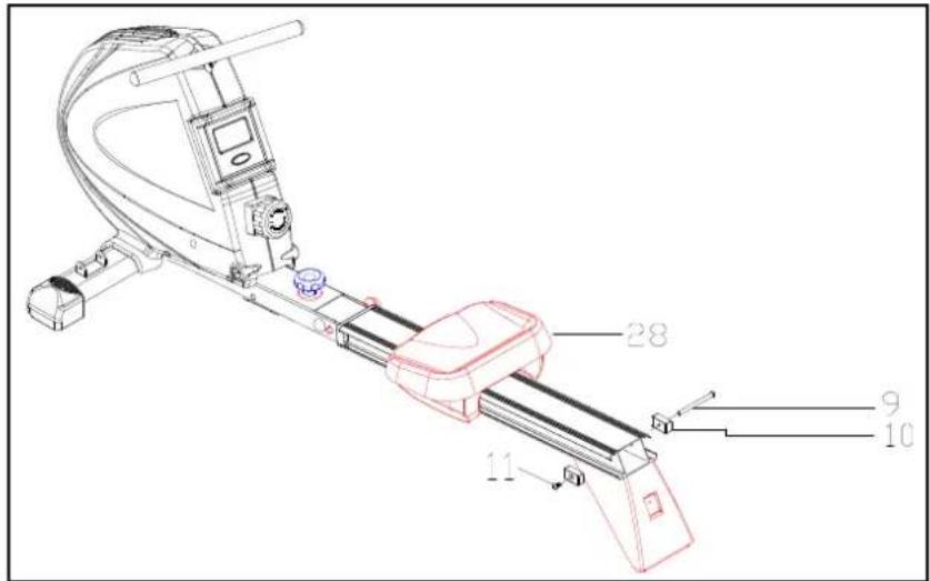
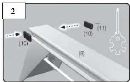
Put the seat (28) on the aluminum sliding tube (8), use the M6*1.0*12(9) through the end of aluminum sliding tube (8), the insert the Seat block(10), lock them with screw M6*10(11)
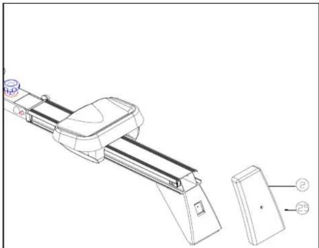
5. Rear stabilizer cover
Attach the cover (2) to the rear stabilizer (3) and lock it up with screw M5*10(101)
natural_image
Technical line drawing of a mechanical device with two labeled parts (② and ⑤), no readable text or symbols present.6. Assembly for slide tube bottom cover
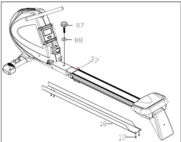
- Remove the pull pin (37)
2.loosen knob(87) and flat washer(88)
3.Fold the aluminum sliding tube, insert the pull pin (37) - use the bottom cover (18) cover the underside of aluminum sliding tube, lock them with screw M5*8 (12)
7. Assembly for Pedal fixing axle
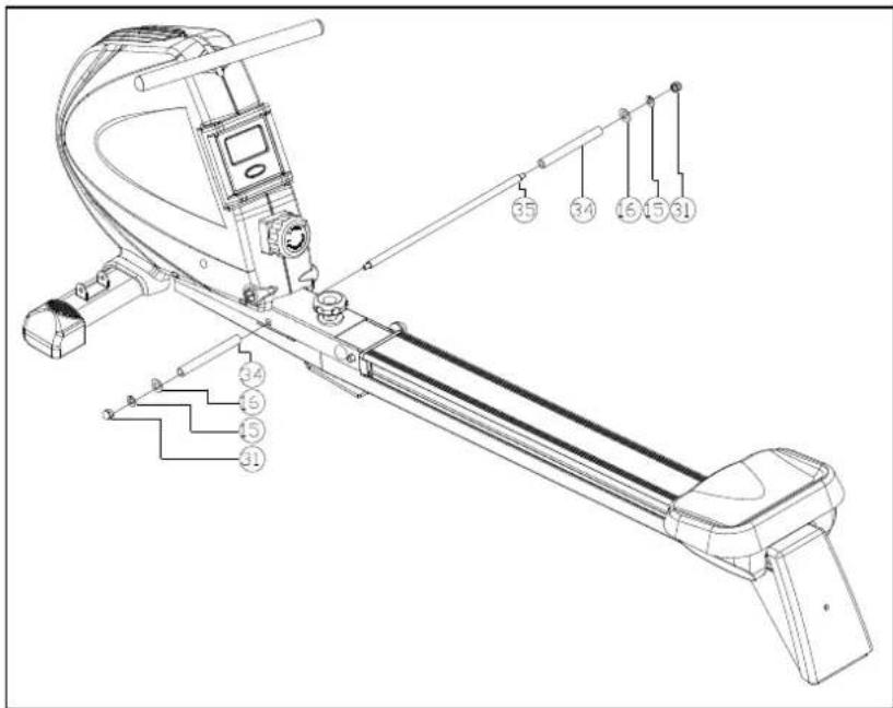
Insert the pedal fixing axle (35) through main frame (39), lock it up with pedal fixing tube (34), flat washer OD22*ID8.5*1.5T(16), M8 spring washer (15) and M8 nut (31).
8. Assembly for Pedal
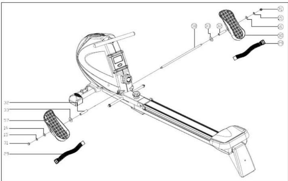
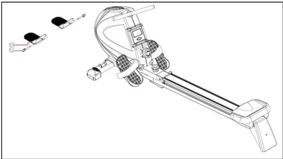
First insert the pedal axle (58) through the main frame Insert pedal separating tube (32), flat washer OD22*ID13*2.0T (33) And pedal (30,57), then lock it up with the flat washerOD22*ID8.5*1.5T(16), M8 spring washer(15) and M8 nut (31)
9. Assembly for Front stand
Remove the lock pin (51) preassembled in the front stand (52)) Attach the front stand (52) to the front stabilizer (50) and then lock it up with pin
natural_image
Technical line drawing of a stationary exercise machine with four labeled components (no text or symbols present)Before first use, please cut the plastic band on the sliding tube (place marked with scissors sticker).
METER
There are two ways to start the meter
Way one: step the peddal
Way two: press any button on the meter.
Turn off: The meter will turn the functions off automatically with displaying time and temperature when no exercise happens for about 4 minutes.
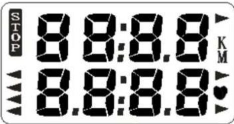
FUNCTION:
COUNT: Accumulates workout counts.
T. COUNT: Accumulates total counts for different exercise session.
TIME: Accumulates workout time.
RPM: Display strokes per minute.
CAL: Accumulate consumed calories during exercise.
SCAN: Automatically scan through COUNT, TIME, TOTAL COUNT, STROKE/MIN, CALORIES, PULSE.
PULSE: Display current heart rate (beat per minute). (Function available only with additional belt)
FUNCTION BUTTON:
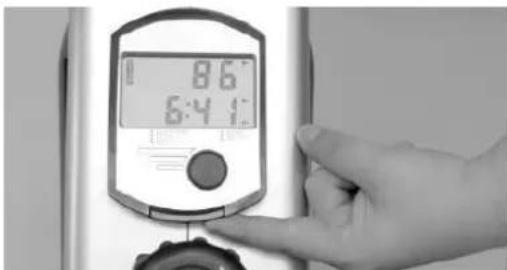
MODE: Press to select function display on the monitor and hold the button for 2 seconds to total reset all function value.
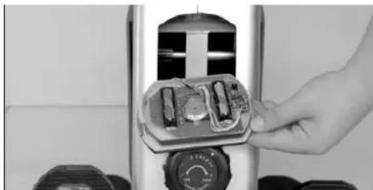
BATTERY REPLACEMENT
natural_image
Hand placing a device into a cylindrical housing (no visible text or symbols)TERMS OF REFERENCES
Rowing machine is use for abdominal, arms and lower body training. ZM1801 is item class H. Unit is not intended for commercial use therapy or rehabilitation.
TRAINING INSTRUCTION
1. Warm-Up
To prevent injury and maximize performance we recommend that each workout period starts with a warm-up. We suggest you do the following exercise as the sketch map. Each exercise at least about 30 seconds.
2. Exercises
natural_image
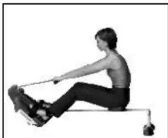
Person performing a row exercise on a machine (no text or symbols visible)To begin the seated row take hold of the handles (Could be like the one shown). Sit with your back straight while keeping your legs bent and feet against the metal block. Extend your arms feeling your lats stretch. Pull the weight back into your body until the handles touch your abdomen. Make sure to bring your shoulder blades as far back as you can and keep your back straight.
Even though we go to great efforts to ensure the quality of each product we produce, occasional errors and/or omissions do occur. In any event should you find this product to has either a defective or a missing part, Please contact us for a replacement.
Consumer service department: ABISAL Sp. z o. o.
ul. Św. Elżbiety 6
41–905 Bytom
abisal@abisal.pl
www.abisal.pl
www.hms-fitness.pl
NÁVOD K OBSLUZE
RADY TÝKAJÍCÍ SE BEZPEČNOSTI
2. MONTÁŽ HLINÍKOVÉ VODICÍ LIŠTY
3. MONTÁŽ ZÁDNÍHO STABILIZÁTORU
natural_image
Close-up of a pen tip with three parallel lines, no visible text or symbols4. MONTÁŽ SEDADLA
5. MONTÁŽ KRYTU ZÁDNÍHO STABILIZÁTORU
natural_image
Technical line drawing of a mechanical device with exploded view and part views (no text or symbols)6. MONTÁŽ SPODNÍHO KRYTU VODICÍ LIŠTY.
8. MONTÁŽ STUPAČEK
9. MONTÁŽ PŘEDNÍHO STABILIZÁTORU
natural_image
Technical line drawing of a stationary exercise machine with three labeled components (no text or symbols present)POČÍTAČ
FUNKCE
natural_image
Close-up of a hand inserting a device into a cylindrical housing (no visible text or symbols)ROZSAH POUŽÍVÁNÍ
natural_image
Person performing a row exercise on a stationary bar (no text or symbols visible)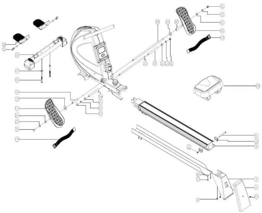



- MONTAŻ ALUMINIOWEJ PROWADNICY
- MONTAŻ TYLNEGO STABILIZATORA
- MONTAŻ SIEDZENIA
- MONTAŻ OSŁONY TYLNEGO STABILIZATORA
- MONTAŻ DOLNEJ OSŁONY PROWADNICY.
- MONTAŻ PEDALÓW.
- MONTAŻ PRZEDNIEGO SŁUPA
- FUNKCJE
- IMPORTANT SAFETY INFORMATION
- SPECIFICATIONS
- MAINTENANCE
- TENSION ADJUSTMENT
- ASSEMBLY INSTRUCTIONS
- Assembly for stabilizer
- Assembly for Aluminum track
- Assembly for rear stabilizer
- Assembly for seat
- Rear stabilizer cover
- Assembly for slide tube bottom cover
- Assembly for Pedal fixing axle
- Assembly for Pedal
- Assembly for Front stand
- METER
- FUNCTION:
- FUNCTION BUTTON:
- BATTERY REPLACEMENT
- TERMS OF REFERENCES
- TRAINING INSTRUCTION
- Warm-Up
- Exercises
- NÁVOD K OBSLUZE
- RADY TÝKAJÍCÍ SE BEZPEČNOSTI
- MONTÁŽ HLINÍKOVÉ VODICÍ LIŠTY
- MONTÁŽ ZÁDNÍHO STABILIZÁTORU
- MONTÁŽ SEDADLA
- MONTÁŽ KRYTU ZÁDNÍHO STABILIZÁTORU
- MONTÁŽ SPODNÍHO KRYTU VODICÍ LIŠTY.
- MONTÁŽ STUPAČEK
- MONTÁŽ PŘEDNÍHO STABILIZÁTORU
- POČÍTAČ
- FUNKCE
- ROZSAH POUŽÍVÁNÍ
Brand : HMS Premium
Model : ZM1801
Category : Rowing Machine