
IAN 59391 - Uncategorized Livarno Lux - Free user manual and instructions
Find the device manual for free IAN 59391 Livarno Lux in PDF.


| Product Type | Halogen Under-Cabinet Light |
| Model Number | IAN 59391 (3005 / 034L or 3005 / 036L) |
| Dimensions (L x W x H) | 60 x 7 x 2.5 cm |
| Primary Power Supply | 230 V ~ 50 Hz |
| Secondary Power Supply | 12 V =, max 3 x 20 W |
| Bulb Type | G4, 12 V, 20 W halogen |
| Number of Bulbs | 3 (4 included, one spare) |
| Motion Sensor | Yes, with adjustable detection range (1.5 - 3 m) |
| Twilight Sensor | Yes, adjustable via LUX control |
| Light-On Time | Adjustable, 20 seconds to 6 minutes |
| Protection Rating | IP20 (indoor use only) |
| Protection Class | II |
| Maximum Series Connection | Up to 3 units of the same model |
| Mounting Hole Distance | 570 mm |
| Installation Type | Wall mounting with screws and dowels |
| Operation | Toggle switch: Off (0), On (1), Motion sensor (2) |
| Included Bulbs | 4 halogen bulbs G4, 12 V, 20 W |
| Cables Included | Mains lead (1.5 m approx.) and connection lead |
| Mounting Hardware | Dowels, screws (for wood and masonry), caps |
| Warranty | 36 months from purchase date |
Frequently Asked Questions - IAN 59391 Livarno Lux
User questions about IAN 59391 Livarno Lux
0 question about this device. Answer the ones you know or ask your own.
Ask a new question about this device
Download the instructions for your Uncategorized in PDF format for free! Find your manual IAN 59391 - Livarno Lux and take your electronic device back in hand. On this page are published all the documents necessary for the use of your device. IAN 59391 by Livarno Lux.
USER MANUAL IAN 59391 Livarno Lux
HALOGEN UNDER-CABINET LIGHT
GB IE
HALOGEN UNDER-CABINET LIGHT
Operation and Safety Notes
SE
HALOGEN-UNDERBELYSNING
Before reading, unfold the page containing the illustrations and familiarise yourself with all functions of the device.
FI
GB / IE Operation and Safety Notes Page 5
flowchart
graph TD
    A["Component 9"] --> B["Assembly"]
    B --> C["Component 10"]
    C --> D["Assembly"]
    D --> E["Component 11"]
    E --> F["Assembly"]
    F --> G["Final Assembly"]
    H["Image of Device 12"] --> I["Arrow pointing to Component 12"]
    style A fill:#f9f,stroke:#333
    style G fill:#bbf,stroke:#333

flowchart
graph TD
    A["Power Source"] --> B["Switch"]
    B --> C["Motor"]
    C --> D["Switch"]
    D --> E["Output Device 14"]
    C --> F["Output Device 8"]
    style A fill:#f9f,stroke:#333
    style E fill:#ccf,stroke:#333
Introduction
Proper use....Page 6
Included items Page 6
Description of parts and features....Page 6
Technical data....Page 6
Safety
Safety advice......Page 7
Preparation
Required tools and materials....Page 8
Preparation for use
Installing the light Page 8
Connecting more than one under-unit light together....Page 8
Operation
Switching the light on/off....Page 9
Adjusting the motion sensor....Page 9
Replacing a bulb....Page 9
Maintenance and cleaning......Page 10
Disposal Page 10
Information
Guarantee Page 10
Manufacturer / Service Page 10
Declaration of Conformity....Page 10
Halogen under-cabinet light
- Introduction

We congratulate you on the purchase of your new device. You have chosen a high quality product. Please read carefully and completely through these operating instructions. Fold out the page with the illustrations. These instructions form part of the product and contain important information about bringing the product into use and its handling. Always observe all the safety advice. Check that the correct mains voltage is available and that all the parts have been properly assembled before bringing into use. Should you have any questions or be uncertain as to how to operate the device, please get in touch with your dealer or service point. Please keep these instructions in a safe place and hand them on to a third party if necessary.
- Proper use
This light is suitable only for interior use, in dry and enclosed spaces. The light should be positioned within reach so that the switch can be operated conveniently. The light can be fitted to all normally inflammable surfaces. Any use other than that described above or modification to the lamp is not permitted and may lead to damage to people or property. Moreover, there is the risk of injury or loss of life and that the lamp may develop technical faults such as short circuit or fire or give an electric shock. This lamp is intended for use only in a domestic environment.
- Included items
Check that all the items and accessories are present and that the lamp is in perfect condition immediately after unpacking.
1 Halogen under-cabinet light,
Model 3005 / 034L or 3005 / 036L
4 Halogen bulbs, G4, 12 V, 20 W
1 Mains lead
1 Connection lead
2 Dowels (for countersunk head screws)
2 Countersunk head screws (for wood)
2 Countersunk head screws (for masonry)
2 Caps
1 Instructions for use
● Description of parts and features
1 Dowel
2 Halogen under-unit light
3 Screw
4 Cap
5 Mains lead
6 Light connector socket
7 Motion sensor
8 Connection socket
9 Time control TIME
10 Day/night control LUX
11 Cover
12 Toggle switch
13 Bulb
14 Connection cable
- Technical data
Operating voltage,
primary: 230V \~ 50Hz
Operating voltage,
secondary: 12V = 3 x 20 W
Dimensions: 60 × 7 × 2.5 cm (L × W × H)
Protection class: II/
Protection class: IP20 (suitable for an indoor environment only)
Bulbs: Halogen bulbs, G4, 12 V, 20 W
Rated power: 3 x 20W
Motion sensor
Light on time
(adjustable): approx. 20 s -
approx. 6 min.
Detection range: approx. 1.5-3m (variesby installation)
Twilight sensor: Yes
● Safety

Safety advice
The right to claim under the guarantee shall be rendered invalid in respect of damage caused by the non-observance of these operating instructions. No liability is accepted for consequent damage. No liability is accepted for damage to property or persons caused by improper handling or non-observance of the safety advice.

To avoid danger to life from electric shock
Before connecting the device to the mains supply, always check the light, mains lead and connection lead for damage. Never use your light if you discover that it is damaged in any way.
CAUTION! A damaged mains lead or connection lead presents a serious danger to life from electric shock.
Before assembly, ensure that the mains voltage available corresponds to the operating voltage necessary of the light (230 V\~).
■ Never let the lamp come into contact with water or other liquids.
■ Never open or insert anything into electrical fittings or equipment. Doing this sort of thing can lead to a serious danger to life from electric shock.
■ Touch only the insulated part of the plug when connecting to or disconnecting from the mains supply.
If the external flexible cable of this lamp is damaged, it may only be replaced by a special cable or a cable that is only available from the manufacturer or his service representative.
■ Connect the under-unit light to the mains supply using the original mains lead only.
■ Connect this light only to other original under-unit lights of the same type (Model 3005 / 034L or 3005 / 036L). Use only the supplied original connection lead to make this connection.
- Use only one mains socket for any series of connected under-unit lights. Ensure that no more than 3 under-unit lights of the same type are connected together in series. Failure to observe this advice could lead to overloading of the connectors and leads.
- First ensure that all the under-unit lights are connected by connection leads before you insert the mains lead into the mains socket.
- Do not attach the light to damp or conductive substrates.

To avoid danger of fire and injury
RISK OF INJURY! Check every bulb and lampshade for damage immediately upon unpacking. Do not operate the light with a defective bulb or glass cover. If they are, contact the service point for a replacement.
RISK OF INJURY FROM BURNS! Ensure the lamp has been switched off and allowed to cool before you touch it. In this way you will avoid the danger of burns. Light bulbs develop a great deal of heat.
- Do not touch bulb components or bulbs as they can reach temperatures > 350 °C during operation.
- Allow the light to cool down completely before replacing a defective bulb.
- Replace defective bulbs immediately. Before replacing the bulb always remove the mains plug from the socket.
- Do not operate this light with a dimmer or an electronic switch. It is not suitable for this mode of operation.
FIRE HAZARD! Fit the light so that it is at least 0.2 m away from the material illuminated. Fire can result
from the development of too much heat.
■ Never leave the light operating unattended.
- Do not allow any objects to cover the light. Fire can result from the development of too much heat.
- Do not allow the lamp or the packaging materials to lie around unattended. Plastic film or
bags, Styrofoam etc. can turn into dangerous toys for children.
Use only halogen bulbs with lamp covers or in low-voltage systems.
- Only use the included parts, using other parts will void the warranty.
- Do not look directly into the light source (light bulb, LED etc.).

For your safety
■ Use only 12 volt halogen bulbs type G4 with a maximum rated power of 20 watts.
■ Fit the light in such a way to ensure it is protected from damp and dirt.
■ Make careful preparations for the assembly and take sufficient time. Clearly lay out all components and any additional tools or materials that might be required so that they are readily to hand.
- Remain alert at all times and always watch what you are doing. Always proceed with caution and do not assemble the lamp if you cannot concentrate or feel unwell.
- Never touch halogen bulbs with your bare hands, otherwise damage to the bulbs may occur. If you find you have touched a bulb with your bare hands, wipe the halogen bulb clean using alcohol and a fluff-free cloth.
● Preparation
● Required tools and materials
The tools and materials mentioned are not included in the delivery. The details and values given are non-binding and for guidance only. The nature of the material depends on the individual circumstances on site.
- Pencil / Marking tool
- Screwdriver
- Electric drill
-
Drill
-
Spirit level
- Cable detector
- Measuring tape
● Preparation for use
- Installing the light
Note: The product includes two different types of screw. Use the countersunk head screws (length: 15 mm) for mounting on to wood. Use the countersunk head screws (length: 25 mm) and the dowels 1 for mounting on to a solid masonry wall.
- Measure up the wall or mounting surface before drilling the holes. Use a spirit level to improve accuracy.
- Mark the two mounting holes at a distance of 570 mm apart.
Steps 3 and 4 apply only to mounting on to solid masonry:
- Now drill the fixing holes (approx. 5 mm, depth approx. 30 mm). Make sure that you do not damage any electrical cables during this operation.
- Insert the supplied dowels 1 into the drilled holes.
- Fix the under-unit light 2 in place with the screws 3 (see Fig. A).
- Place the caps 4 on the screw heads.
- Insert the connector plug of the mains lead 5 into the light connector socket 6.
- Insert the mains plug of the mains lead 5 into the mains socket.
Your light is now ready for operation.
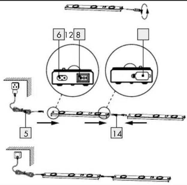
- Connecting more than one under-unit light together
CAUTION! First ensure that all the under-unit lights are connected by connection cable 14 before you insert the mains plug of the mains lead 5 into
the mains socket, otherwise damage to the product may occur.
Note: Ensure that no more than 3 under-unit lights of the same type are connected together in series.
Note: If you install and connect the lights in series (max. 3 No.), they function independently of one another.
☐ Install up to three lights of the same type close to one another. Follow steps 1 to 6 of the section on "Installing the light".
Note: Ensure that the distance between the lights is not greater than 20 cm.
☐ Remove the protective cap from the connection socket 8 by screwing out the screws anticlockwise using a Phillips screwdriver.
☐ Plug the connection cable 14 into the connection socket 8 of the light.
☐ Plug the other end of the connection cable 14 into the light connector socket 6 of the other light.
☐ Insert the connector plug of the mains lead 5 into the light connector socket 6 of the outer right light.
☐ Insert the mains plug 5 into the mains socket.
Your lights are now ready for operation.
Operation
- Switching the light on / off
Note: The under-unit light can be operated with a toggle switch 12 as well as a motion sensor 7.
The toggle switch has the following functions:
- Toggle switch in position 0: Light and motion sensor are switched off.
- Toggle switch in position 1: Light switched on, motion sensor deactivated.
- Toggle switch in position 2: Motion sensor activated. The light only is only switched on by the motion sensor.
- Adjusting the motion sensor
Note: The motion sensor is fitted with a twilight sensor. You can set the sensitivity of the twilight sensor with the day / night control LUX10 and the lighting period with the time control TIME 9.
Setting the light sensitivity:
☐ Turn the day / night control LUX ^10 anticlockwise to increase the light sensitivity (motion sensor ^7 reacts at a darker stage of twilight).
☐ Turn the day / night control LUX ^10 clockwise to reduce the light sensitivity (motion sensor 7 reacts at lighter stage of twilight).
Setting the lighting period:
☐ Turn the time control TIME 9 anticlockwise to shorten the lighting period (min. 20 s).
☐ Turn the time control TIME 9 clockwise to lengthen the lighting period (max. 6 Min.).
Note: The motion sensor 7 of the under-unit light reacts to heat. As the room temperature rises the sensitivity of the motion sensor reduces (takes longer to react).
● Replacing a bulb
WARNING! RISK OF ELECTRIC SHOCK!
To replace the bulb 13, first of all disconnect the light from the mains circuit. Pull the mains plug of the mains lead 5 out of the mains socket.
CAUTION! RISK OF BURNS! Let the bulbs cool down fully before you replace them.
□ Turn the cover 11 anticlockwise and take it off.
☐ Draw the defective bulb 13 in the direction of the arrow out of the fitting socket (see Fig. B).
Note: Use only a halogen bulb type G4 12 volt with a maximum rated power of 20 W.
Note: Use a soft, fluff-free cloth when you are replacing a bulb 13. Never touch the bulb 13 with your bare hands.
☐ Insert a new bulb 13 into the fitting socket.
☐ Put the cover 11 back in place and turn it clockwise to tighten it.

CAUTION! First ensure that all the under-unit lights are connected by connection leads 14 before you insert the plug of the mains lead 5 into the mains socket, otherwise damage to the product may occur.
☐ Insert the mains plug of the mains lead 5 into the mains socket.
● Maintenance and cleaning

CAUTION! RISK OF ELECTRIC SHOCK!
Pull the mains plug of the mains lead 5 out of the mains socket.

CAUTION! RISK OF ELECTRIC SHOCK!
For electrical safety reasons, never clean the light with water or other fluids nor immerse it in water.
- Do not use solvents such as petrol and the like, as they could damage the light.
□ Allow the light to cool completely.
☐ Use a dry, fluff-free cloth for cleaning.

Disposal
The packaging and ancillary packing consist entirely of environmentally-friendly materials. They can be disposed of at your local recycling facility.

The symbol of the wheelie bin with the line through it means that, in the European Union, the product has to be disposed of in a separate refuse collection. This applies to the product and to all components bearing this symbol. Products marked in this way may not be disposed of along with normal domestic waste but have to be handed in at a recycling collection point for electrical and electronic appliances. Recycling helps to reduce the consumption of raw materials and to ease the burden on the environment.

Information

Guarantee
You receive a 36 month warranty on this product, valid from the date of purchase. The device has been carefully produced under strict quality control. Within the warranty period we shall rectify without charge all material and manufacturing defects. In the event of a defect arising during the warranty period, please send the device to the listed Service Centre address, making reference to the following article number: 3005/034L or 3005/036L.
Wear parts (such as bulbs) and damage caused by improper handling, non-observance of the operating instructions or unauthorised interference are excluded from the warranty. The performance of services under the warranty does not extend or renew the warranty period.

Manufacturer / Service
For all inquiries about your product, please have your receipt and product number (e.g. IAN 12345) ready as your proof of purchase.

Declaration of Conformity CE
This product fulfils the requirements of the applicable European and national directives (Electromagnetic Compatibility 2004/108/EC, Low Voltage Directive 2006/95/EC), Ecodesign directive 2009/125/EC, RoHS directive 2011/65/EU).
Conformity has been demonstrated. The relevant declarations and documents are held by the manufacturer.
Johdanto
WAARSCHUWING! GEVAAR VOOR
59929 Brilon (Germany)
Last Information Update · Tietojen tila · Informationsstatus
Tilstand af information · Stand van de informatie · Stand
- HALOGEN UNDER-CABINET LIGHT
- HALOGEN-UNDERBELYSNING
- Introduction
- Safety
- Preparation
- Preparation for use
- Operation
- Maintenance and cleaning......Page 10
- Information
- - Introduction
- - Proper use
- - Included items
- ● Description of parts and features
- - Technical data
- Motion sensor
- ● Safety
- Safety advice
- To avoid danger to life from electric shock
- To avoid danger of fire and injury
- For your safety
- ● Preparation
- ● Required tools and materials
- ● Preparation for use
- - Installing the light
- Steps 3 and 4 apply only to mounting on to solid masonry:
- - Connecting more than one under-unit light together
- - Switching the light on / off
- The toggle switch has the following functions:
- - Adjusting the motion sensor
- Setting the light sensitivity:
- Setting the lighting period:
- ● Replacing a bulb
- WARNING! RISK OF ELECTRIC SHOCK!
- ● Maintenance and cleaning
- CAUTION! RISK OF ELECTRIC SHOCK!
- Disposal
- Guarantee
- Manufacturer / Service
- Declaration of Conformity CE
- Johdanto
- WAARSCHUWING! GEVAAR VOOR
Brand : Livarno Lux
Model : IAN 59391
Category : Uncategorized