
MHSC2002E - Hedge Trimmer EGO - Free user manual and instructions
Find the device manual for free MHSC2002E EGO in PDF.


| Product type | Accessory for pole hedge trimmer |
| Brand | EGO |
| Model | MHSC2002E |
| Blade length | 51 cm |
| Maximum cutting capacity | 26 mm |
| Weight (without battery) | 2.28 kg |
| Power source | 56 V lithium-ion battery (compatible with PH1400E power head) |
| Number of blade positions | 12 positions (4 upward, 7 downward, 1 straight) |
| Guaranteed sound power level | 95 dB(A) |
| Vibration level (front handle) | 2.8 m/s² |
| Vibration level (rear handle) | 3.0 m/s² |
| Cutting system | Dual action blades |
| Handles | Adjustable front handle, rear handle with safety switch |
| Included guards | Blade guard, end cap |
| Maintenance | Gear lubrication every 50 h; blade sharpening if necessary |
| Warranty | See EGO Power Plus website |
Frequently Asked Questions - MHSC2002E EGO
User questions about MHSC2002E EGO
0 question about this device. Answer the ones you know or ask your own.
Ask a new question about this device
Download the instructions for your Hedge Trimmer in PDF format for free! Find your manual MHSC2002E - EGO and take your electronic device back in hand. On this page are published all the documents necessary for the use of your device. MHSC2002E by EGO.
USER MANUAL MHSC2002E EGO
natural_image
Technical line drawing of a mechanical tool with a long shaft and serrated end (no text or symbols)OPERATOR'S MANUAL
HEDGE TRIMMER
ATTACHMENT
MODEL NUMBER HTA2000
EN Hedge trimmer attachment 5
natural_image
Line drawing of a mechanical tool or device with a lever and handle (no text or symbols)




natural_image
Illustration of a person spraying crops in a field, with arrows indicating direction (no text or symbols)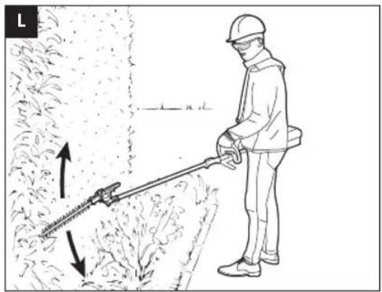
natural_image
Illustration of a person using a manual power shaver to clean vegetation, with arrows indicating direction (no text or symbols)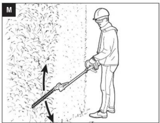
natural_image
Illustration of a worker using a manual power shoveling machine to brush through dense vegetation (no text or symbols)
natural_image
Line drawing of a person spraying water in a field, no text or symbols present
natural_image
Technical line drawing of a mechanical lever assembly with a black arrow pointing to a component (no text or symbols present)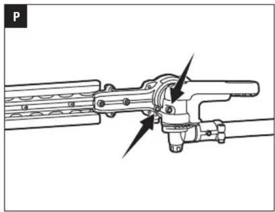
natural_image
Technical line drawing of a mechanical assembly with no visible text or symbolsREAD ALL INSTRUCTIONS!

READ OPERATOR'S MANUAL
⚠️ Residual risk! People with electronic devices, such as pacemakers, should consult their physician(s) before using this product. Operation of electrical equipment in close proximity to a heart pacemaker could cause interference or failure of the pacemaker.
WARNING: To ensure safety and reliability, all repairs and replacements should be performed by a qualified service technician.
SAFETY SYMBOLS
The purpose of safety symbols is to attract your attention to possible dangers. The safety symbols and the explanations with them deserve your careful attention and understanding. The symbol warnings do not, by themselves, eliminate any danger. The instructions and warnings they give are no substitutes for proper accident prevention measures.
WARNING: Be sure to read and understand all safety instructions in this Operator's Manual, including all safety alert symbols such as "DANGER," "WARNING," and "CAUTION" before using this tool. Failure to follow all instructions listed below may result in electric shock, fire, and/or serious personal injury.
SYMBOL MEANING
SAFETY ALERT SYMBOL: Indicates DANGER, WARNING, OR CAUTION. May be used in conjunction with other symbols or pictographs.

WARNING: The operation of any power tools can result in foreign objects being thrown into your eyes, which can result in severe eye damage. Before beginning power tool operation, always wear safety goggles or safety glasses with side shields and a full face shield when needed. We recommend a Wide Vision Safety Mask for use over eyeglasses or standard safety glasses with side shields.
SAFETY INSTRUCTIONS
This page depicts and describes safety symbols that may appear on this product. Read, understand, and follow all instructions on the machine before attempting to assemble and operate it.
 | Safety Alert | Indicates a potential personal injury hazard. |
 | Read Operator's Manual | To reduce the risk of injury, user must read and understand the operator's manual before using this product. |
 | Wear Eye Protection | Always wear safety goggles or safety glasses with side shields and a full face shield when operating this product. |
 | Wear Ear Protection | Always wear ear protection when operating this product. |
 | Blade Length | The length of the blade |
 | Cutting Capacity | Max. Cutting capacity of the blade |
 | Keep hands and feet away from the cutting tool | Never attempt to operate your power tool with one hand. Loss of control of the power tool resulting in serious or fatal injury may result. To reduce the risk of cut injuries, keep hands and feet away from the cutting tool. Never attach a moving cutting tool with your hand or any other part of your body. |
 | Keep Bystanders Away | Ensure that other people and pets remain at least 15m away from the hedge trimmer when it is in use. |
 | Do Not Expose To Rain | Do not use in the rain or leave outdoors while it is raining. |
 | CE | This product is in accordance with applicable EC directives. |
EN
 | WEEE | Waste electrical products should not be disposed of with household waste. Take to an authorized recycler. |
 | Noise | Guaranteed sound power level. Noise emission to the environment according to the European community's Directive. |
| mm Millimeter Length or size | ||
| V Volt Voltage | ||
| cm Centimeter Length or size | ||
| in. Inch Length or size | ||
| kg Kilogram Weight | ||
IMPORTANT SAFETY INSTRUCTIONS
WARNING! When using electric gardening appliances, basic safety precautions should always be followed to reduce the risk of fire, electric shock, and personal injury, including the following:
READ CAREFULLY BEFORE USE
KEEP FOR FUTURE REFERENCE
DANGER! Do not operate near electrical power lines.
The unit has not been designed to provide protection from electric shock in the event of contact with overhead electric lines, Consult local regulations for safe distances from overhead electric power lines and ensure that the operating position is safe and secure before operating the tool.
HEDGE TRIMMER SAFETY WARNINGS
DANGER! Keep hands away from blade. Contact with blade will result in serious personal injury.
- Keep all parts of the body away from the cutter blade. Do not remove cut material or hold material to be cut when blades are moving. Make sure the switch is off when clearing jammed material. A moment of inattention while operating the hedge trimmer may result in serious personal injury.
- On machines with a defined transport position (cutting blade folded flat against the hedge trimmer shaft): Never start the machine in the transport position, since the blades are not engaged in that position and you therefore cannot visually check to see that they will be stopped at idle when you start to adjust the cutting blade to the desired cutting position (where the blades are engaged).
- Carry the hedge trimmer by the handle with the cutter blade stopped. When transporting or storing the hedge trimmer always fit the cutting device cover. Proper handling of the hedge trimmer will reduce possible personal injury from the cutter blades.
■ Do not grasp the exposed cutting blades or cutting edges when picking up or holding the hedge trimmer. - Hold the power tool by insulated gripping surfaces only, because the cutter blade may contact hidden wiring. Cutter blades contacting a "live" wire may make exposed metal parts of the power tool "live" and could give the operator an electric shock.
- Keep cable away from cutting area. During operation the cable may be hidden in shrubs and can be accidentally cut by the blade.
- Check the hedge for foreign objects before operating, e.g. wire fences.
-
To reduce the risk of injury from loss of control, be absolutely sure that the cutting blade is clear of you and all other obstructions and objects, including the ground, because when the tool starts, the motor speed will be fast enough to engaged and move the cutting blade on the tool.
-
Do not allow other persons in the general work area. Ensure that other people and pets remain at least 15m away from the hedge trimmer when it is in use.
■ Never allow children to operate the hedge trimmer.
■ Use both hands when operating the hedge trimmer. Using one hand could cause loss of control and result in serious personal injury. - Do not overreach. Keep proper footing and balance at all times. Special care must be taken in slippery conditions (wet ground, snow) and in difficult, overgrown terrain. Watch for hidden obstacles such as tree stumps, roots and ditches to avoid fallen branches, scrub and cuttings. Be extremely cautious when working on slopes or uneven ground.
- Do not use on a ladder, rooftop, tree, or other unstable support. Stable footing on a solid surface enables better control of the hedge trimmer in unexpected situations.
-
Observe the cutting blades at all times – do not cut any area if the hedge that you cannot see. When cutting the top of a taller hedge, check the other side of the hedge frequently for bystanders, animals and obstructions.
-
Check damaged parts before further use of the hedge trimmer. Check for alignment of moving parts, binding of moving parts, breakage of parts, mounting, and any other condition that may affect its operation.
- Check the blade and motor mounting bolts at frequent intervals for proper tightness. Also, visually inspect blade for damage (e.g., bent, cracked, and worn). Replace the blade only with a blade from EGO™.
■ Replace the blade if it is bent or cracked. An unbalanced blade causes vibration that could damage the motor drive unit or cause personal injury.
■ If the equipment should start to vibrate abnormally, stop the motor and check immediately for the cause. Vibration is generally a warning of trouble.
■ The trimmer shall be used to cut stems less than 26mm thick.
■ Trim only in daylight or in good artificial light.
■ Do not use the battery-operated hedge trimmer in rain
ADDITIONAL WARNINGS
■ Do not charge the battery pack in rain or in wet locations.
■ Use only with the battery packs and chargers listed below: SAVE THESE INSTRUCTIONS
| BATTERY PACK CHARGER | |
| BA1120E, BA2240E, BA2800, BA3360, BA4200 | CH2100ECH5500E |
■ The battery pack must be removed from the appliance before it is scrapped.
■ The battery shall be disposed of safely.
- Do not dispose of the battery in a fire. The cells may explode. Check with local codes for possible special disposal instructions.
- Do not open or mutilate the battery. Released electrolyte is corrosive and may cause damage to the eyes or skin. It may be toxic if swallowed.
CAUTION! The electrolyte is a dilute sulfuric acid that is harmful to the skin and eyes. It is electrically conductive and corrosive.
■ Exercise care in handling batteries in order not to short the battery with conducting materials such as rings, bracelets, and keys. The battery or conductor may overheat and cause burns.
■ Battery tools do not have to be plugged into an electrical outlet; therefore, they are always in operating condition. Be aware of possible hazards even when the tool is not operating. Take care when performing maintenance or service.
■ Remove the battery pack before servicing, clean or removing material from the tool.
■ Replacement Parts - When servicing, use only identical EGO replacement parts. Use of any other accessory or attachment may increase the risk of injury.
- Have your power tool serviced by a qualified repair person using only identical replacement parts. This will ensure that the safety of the power tool is maintained.
■ Do not wash with a hose; avoid getting water in motor and electrical connections.
■ Store the tool in a dry and high or locked location out of reach of children.
■ If situations occur that are not covered in this manual, use care and good judgment. Contact the EGO Service Center for assistance.
Save these instructions. Refer to them frequently and use them to instruct others who may use this tool. If you lend this tool to someone else, also lend these instructions to them to prevent misuse of the product and possible injury.
SAVE THESE INSTRUCTIONS
NOTE: SEE YOUR POWER HEAD OPERATOR'S MANUAL FOR ADDITIONAL SPECIFIC SAFETY RULES.
SPECIFICATIONS
| Blade Length 51 cm | ||
| Cutting Capacity 26 mm | ||
| Weight (Without battery pack) 2.28 kg | ||
| Measured sound power level L_WA | 92.3 dB(A)K=2.72 dB(A) | |
| Sound pressure level at operator's ear L_PA | 80.4 dB(A)K=3 dB(A) | |
| Guaranteed sound power level L_WA (measured according to 2000/14/EC) | 95 dB(A) | |
| Valuation of vibration a_h | Front-assist handle | 2.8 m/s ^2 K=1.5 m/s ^2 |
| Rear handle | 3.0 m/s ^2 K=1.5 m/s ^2 | |
■ The above parameters are tested and measured equipped with power head PH1400E;
■ The declared vibration total value has been measured in accordance with a standard test method and may be used for comparing one tool with another;
■ The above parameters are tested and measured equipped with power head PH1400E;
EN
■ The declared vibration total value may also be used in ADJUSTING THE CUTTING BLADE
a preliminary assessment of exposure.
NOTICE: The vibration emission during actual use of the power tool can differ from the declared value in which the tool is used; In order to protect the operator, user should wear gloves and ear protectors in the actual conditions of use.
PACKING LIST
| PART NAME QUANTITY | |
| Hedge Trimmer Attachment 1 | |
| Wrench 1 | |
| Blade Scabbard 1 | |
| Operator's Manual 1 |
DESCRIPTION
KNOW YOUR HEDGE TRIMMER ATTACHMENT (Fig. A)
- Cutting Blade
- Quadrant
- Trigger
- Hedge Trimmer Shaft
- Soft Sleeve
- End Cap
- Adjusting Lever
- Gear Case
- Wrench
- Blade Scabbard
- Tip Protector (Optional, SOLD SEPARATELY)
ASSEMBLY
⚠ WARNING: If any parts are damaged or missing, do not operate this product until the parts are replaced. Use of this product with damaged or missing parts could result in serious personal injury.
WARNING: Do not attempt to modify this product or create accessories not recommended for use with this hedge trimmer. Any such alteration or modification is misuse and could result in a hazardous condition leading to possibly serious personal injury.
WARNING: Never attach or adjust any attachment while the power head is running or with the battery installed. Failure to stop the motor and remove the battery may cause serious personal injury.
When the hedge trimmer is removed from the package, it is folded in its storage position where the cutting blade is against the shaft (Fig. B). It is recommended to adjust the cutting blade to a suitable working position before attaching it to the power head.
There are 12 possible working positions. The angle of the cutting blade can be adjusted upwards in 4 stages from 0° (straight) to 45°, and downwards in 7 stages from 0° to 90° (right angle facing down) (Fig. C).
- Press the trigger on the adjusting lever and meanwhile rotate the adjusting lever to adjust the cutting blade to the desired cutting position (Fig. D).
- Once the desired position has been reached, release the trigger. An audible click indicates that the locking pin is engaged in the quadrant, right located into place (Fig. D).
Fig. D parts description see below:
D-1 Quadrant
D-2 Locking Pin
WARNING: To reduce the risk of injury, carry out the adjustment only when the cutting blades are at a standstill. Never touch the blades while making adjustments.
WARNING: To reduce the risk of injury, always stop the tool and fit the blade scabbard before moving the cutting blade to the storage position or from the storage position to the normal working position.
CONNECTING/REMOVING THE HEDGE TRIMMER ATTACHMENT TO THE POWER HEAD
This hedge trimmer attachment is designed for use with EGO 56V LITHIUM-ION Power Head PH1400E. Besides top cutting, there is a side-cutting position in the hedge trimmer shaft for connecting with the power head (Fig. E). Detail working techniques please see “WORKING TECHNIQUES” section in this manual.
Fig. E parts description see below:
E-1 Top Cut Position
E-2 Side Cut Position
See "INSTALLING AN ATTACHMENT TO THE POWER
HEAD "section in the power head PH1400E operator's manual for connecting the hedge trimmer to the power head.
See “REMOVING THE ATTACHMENT FROM THE POWER HEAD” section in the power head PH1400E operator's manual to remove the hedge trimmer from the power head.
MOUNTING THE TIP PROTECTOR (Optional)
- Use a 3mm hex wrench to remove the short bolt, plain washer, bush and nut at the end of the cutting blade (Fig. F). Save the plain washer, bush and nut for reassembly.
Fig. F parts description see below:
| F-1 Nut F-3 Plain Washer | ||
| F-2 Bush F-4 Short Bolt |
- Align the tip protector with the bulge on the cutting blade and mount it into place. Secure it with the new long bolt and nut as well as the saved washer, bush and nut (Fig. G).
Fig. G parts description see below:
| G-1 Nut G-4 Bush | ||
| G-2 Tip Protector G-5 Plain Washer | ||
| G-3 Nut G-6 Long Bolt | ||
OPERATION
DANGER: Never cut near power lines, electric cords, or other electric sources. If the cutting blades jam on any electrical cord or line, DO NOT TOUCH THE CUTTING BLADE OR THE ALUMINUM POLE! THEY CAN BECOME ELECTRICALLY LIVE AND MAY BE VERY DANGEROUS.
Continue to hold the hedge trimmer by the insulated rear handle or lay it down and away from you in a safe manner. Disconnect the electrical service to the damaged line or cord before attempting to free the cutting blade from the line or cord. Contact with the cutting blade, other conductive parts of the hedge trimmer or live electric cords or lines will result in death by electrocution or serious injury.
WARNING: Do not allow familiarity with this product to make you careless. Remember that a careless fraction of a second is sufficient to inflict serious injury.
WARNING: Always wear eye protection, along with hearing protection. Failure to do so could result in objects being thrown into your eyes and other possible serious injuries.
Before each use, inspect the entire product for damaged, missing, or loose parts such as screws, nuts, bolts, caps, etc. Tighten securely all fasteners and caps and do not operate this product until all missing or damaged parts are replaced.
WARNING: To prevent serious personal injury, remove the battery pack from the tool before servicing, cleaning, changing attachments or removing material from the unit.
After each use, clean the tool.
See the Maintenance section for cleaning instructions.
APPLICATIONS
You may use this product for trimming the hedges, shrubs, scrub, bushes and similar material with a branch diameter of less than 26 mm.
NOTICE: The tool is to be used only for its prescribed purpose. Any other use is deemed to be a case of misuse.
USING THE HEDGE TRIMMER WITH POWER HEAD
WARNING: Dress properly to reduce the risk of injury when operating this tool. Do not wear loose clothing or jewelry. Wear eye and ear/hearing protection. Wear heavy, long pants, boots and gloves. Do not wear short pants or sandals or go barefoot.
PREPARATION FOR CUTTING:
- Adjusting the cutting blade to the desired working position.
- Remove the blade scabbard from the cutting blade.
- For safe and better operation, put on the shoulder strap across the shoulder. Adjust the shoulder strap into a comfortable operating position. Following the instructions in the section "MOUNTING THE SHOULDER STRAP" in PH1400E operator's manual to attach the shoulder strap onto the power head.
WARNING: The shoulder strap is also a quick release mechanism in hazardous situation. When an emergency occurs, take it off your shoulder immediately, no matter what way the strap is in.
WORKING TECHNIQUES
- Horizontal Cutting (with cutting blade at an angle): Cut close to the ground from a standing position, e.g. low shrubs.
Swing the cutting blade up and down as you move along the hedge – use both sides of the cutting blades, do not rest the cutter blade on the ground (Fig. H).
EN
■ Horizontal Cutting (with straight cutting blade)
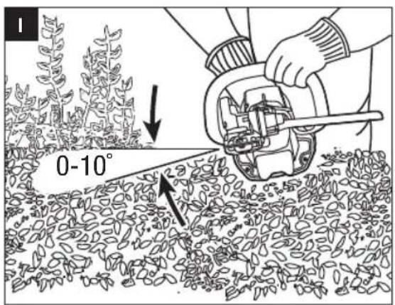
Hold the cutting blade at an angle of 0^ to 10^ as you swing the hedge trimmer horizontally. Swing the cutting blade in an arc towards the outsides of the hedge so that the cuttings are swept to the ground (Fig. I, J & K).
Recommendation: Only cut hedges that are no more than chest height in this working position.
■ Vertical Cutting (with cutting blade at an angle):
Cutting without standing directly next to the hedge, e.g. flowerbed between operator and hedge.
In this cutting position, for your better control of the hedge trimmer, it is recommended that connect the hedge trimmer with the power head at the side-cutting position (see Fig. E).
Swing the cutting blade up and down in an arc as you move along the hedge – use both sides of the cutting blade (Fig. L).
■ Vertical Cutting (with straight cutting blade):
Extra long reach without the need for other aids.
Swing the cutting blade up and down in an arc as you move along the hedge – use both sides of the cutting blade (Fig. M).
■ Overhead Cutting (with cutting blade at an angle)
Hold the hedge trimmer vertically and swing it in an arc to make maximum use of its reach (Fig. N). For extreme high hedge, the extension pole is suitable for aids in trimming.
WARNING: Any working position above head height is tiring. To minimize the risk of accidents, work in such positions for short periods only. Set angle of adjustable cutting blade to maximum so that the tool can be held in a lower, less tiring position (with shoulder strap) while still providing adequate reach.
TO START/STOP THE TOOL
See "STARTING/STOPPING THE POWER HEAD" section in the power head PH1400E operator's manual.
MAINTENANCE
WARNING: Before inspecting, cleaning or servicing the unit, stop the motor, wait for all moving parts to stop, and remove the battery pack. Failure to follow these instructions can result in serious personal injury or property damage.
WARNING: When servicing, use only identical replacement parts. Use of any other parts can create a hazard or cause product damage. To ensure safety and reliability, all repairs should be performed by a qualified service technician.
GENERAL MAINTENANCE
Avoid using solvents when cleaning plastic parts. Most plastics are susceptible to damage from various types of commercial solvents and may be damaged by their use. Use clean cloths to remove dirt, dust, oil, grease, etc.
CLEAN THE UNIT
■ Use a soft brush to remove debris from all air intakes and cutting blade.
■ To remove pitch and other sticky residue, spray the blades with resin solvent. Run the motor briefly so that the solvent is evenly distributed.
- Do not use any strong detergents on the plastic housing or the handle. They can be damaged by certain aromatic oils, such as pine and lemon, and by solvents such as kerosene. Moisture can also cause a shock hazard. Wipe off any moisture with a soft dry cloth. Never use water for cleaning the tool.
SHARPENING THE CUTTING BLADE
When cutting performance and behavior begin to deteriorate, i.e. blades frequently snag on branches: Resharpen the cutting blades.
It is recommended to have the cutting blades resharpened by a qualified service technician.
NOTICE: Do not operate your hedge trimmer with dull or damaged cutting blades. This may cause overload and will give unsatisfactory cutting results.
LUBRICATING THE BLADE
To prevent rust, it is recommended to lubricate the blades with anti-rusting oil when it is stored for long time.
WARNING: Blades are sharp. When handling the blade assembly, wear non-slip, heavy-duty protective gloves. Do not place your hand or fingers between blades or in any position where they could get pinched or cut. NEVER touch blades or service the unit with battery pack installed.
The transmission gears in the gear case need to be lubricated periodically with gear grease. Check the gear case grease level about every 50 hours of operation by removing the sealing screw on the gear case. There are three sealing screws with one on the side and two on the top.
If no grease can be seen on the flanks of the gear, follow the steps below to fill with gear grease up to 3/4 capacity.
Do not completely fill the transmission gears.
- Depending on which screw you are removing, hold the hedge trimmer on its side or lay it on its back so that the sealing screw to be removed is facing upwards (Fig. O & P).
- Use the wrench provided to loosen and remove the sealing screw.
- Use a grease syringe (not included) to inject some grease into the screw hole; do not exceed 3/4 capacity.
- Tighten the sealing screw after injection.
STORING THE UNIT
■ Remove the battery pack from the tool.
■ Clean the tool thoroughly before storing it.
- Put on the blade scabbard onto the cutting blade before storing or transporting. Use caution to avoid the sharp teeth of the blades. For saving space, it is recommended to fold the hedge trimmer to its storage position (see Fig. B).
■ If the hedge trimmer is removed from the power head and stored separately, fit the end cap on the attachment shaft to avoid dirt getting into the coupler.
■ Store the unit in a dry, well-ventilated area, locked-up or up high, out of the reach of children. Do not store the unit on or adjacent to fertilizers, gasoline, or other chemicals.
Protecting the environment
Do not dispose of electrical equipment, battery charger and batteries/rechargeable batteries into household waste!
According to the European law 2012/19/EU, electrical and electronic equipment that is no longer usable, and according to the European law 2006/66/EC, defective or used battery packs/batteries, must be collected separately.
If electrical appliances are disposed of in landfills or dumps, hazardous substances can leak into the groundwater and get into the food chain, damaging your health and well-being
EC DECLARATION OF CONFORMITY

EN
We, EGO EUROPE GMBH.
Declare that the product 56V lithium-ion cordless hedge trimmer attachment HTA2000, equipped with power head PH1400E
Complies with the essential health and safety requirements of the following Directives:
2006/42/EC, 2014/30/EU, 2011/65/EU, 2000/14/EC
Standards and technical specifications referred to:
EN 60745-1, EN ISO 10517, EN 55014-1, EN 55014-2
Measured Sound Power Level: 92.3 dB(A)
Guaranteed Sound Power Level: 95 dB(A)
* (The above parameters are tested and measured equipped with the power head)


Peter Melrose Dong Jianxun
Managing Director of
EGO Europe GmbH Chervon
Quality Manager of
(Authorized representative for CHERVON and responsible for technical documentation)
01/12/2016
EN TROUBLESHOOTING
| PROBLEM | CAUSE SOLUTION | |
| Hedge Trimmer does not work. | The battery pack is not attached to the hedge trimmer.No electrical contact between the hedge trimmer and battery.The battery pack is depleted.The lock-off button is not depressed before pressing the trigger.The battery pack or power head is too hot.The blade is jammed.The hedge trimmer is not well connected with the power head. | Attach the battery pack to the hedge trimmer.Remove battery, check contacts and reinstall the battery pack.Charge the battery pack.Press down the lock-off lever and hold it, then depress the trigger to turn on the tool.Allow the battery pack or power head to cool until the temperature drops below 152°F (67°C).Remove the battery pack from the tool. Remove the obstruction carefully and then reinsert the battery and restart the tool.Disconnect the hedge trimmer from the power head. Reconnect them following the section“INSTALLING AN ATTACHMENT TO THE POWER HEAD” in PH1400E operator’s manual. |
| Excessive vibration or noise. | Dry or corroded blades.Blades or blade support is bent.Bent or damaged teeth.Loose blade bolts. | Lubricate the blades.Replace with a new blade or support. Contact EGO service center for blade or support replacement.Replace with a new blade or support. Contact EGO service center for blade or support replacement.Tighten the blade bolts. Using a 3mm wrench, (not included), turn the bolt clockwise to tighten. |
WARRANTY
EGO WARRANTY POLICY
Please visit the website egopowerplus.com for full terms and conditions of the EGO Warranty policy.
DÉCLARATION DE CONFORMITÉ CE
CE
Nous, EGO EUROPE GMBH
2006/42/CE, 2014/30/UE, 2011/65/UE, 2000/14/CE
2006/42/CE, 2014/30/UE, 2011/65/UE, 2000/14/CE
2006/42/CE, 2014/30/UE, 2011/65/UE, 2000/14/CE
VEILIGHEIDSWAARSCHUWINGEN VOOR HEGGENSCHAREN
HET APPARAAT SCHOONMAKEN
HET APPARAAT OPBERGEN
RENG∅RING AF APPARATET
OPBEVARING AF APPARATET
Fig. G parts description see below:
| G-1 | Mutter G-4 Hylse | ||
| G-2 | Tuppbeskytter G-5 Underlagsskive | ||
| G-3 | Mutter G-6 Lang skrue | ||
DRIFT
GENERELT VEDLIKEHOLD
DEKLARACJA ZGODNOŚCI WE

We, EGO EUROPE GMBH
2006/42/WE, 2014/30/UE, 2011/65/UE, 2000/14/WE
POLITYKA GWARANCYJNA EGO
DÔLEŽITÉ BEZPEČNOSTNÉ POKYNY
MONTÁŽ OCHRANY HROTU (volitel'ne)
2006/42/CE, 2014/30/UE, 2011/65/UE, 2000/14/CE
Fig. G parts description see below:
LUGEGE KASUTUSJUHENDIT
OLULISED OHUTUSJUHISED
| AKU LAADIJA | |
| BA1120E, BA2240E, BA2800, BA3360, BA4200 | CH2100ECH5500E |
natural_image
Technical line drawing of a mechanical device with no visible text or symbolsOPERATOR'S MANUAL
56-VOLT LITHIUM-ION
CORDLESS POWER HEAD
MODEL NUMBER PH1400E
EN 56 volt multi tool power head 4
natural_image
Line drawing of a ElGO sportswear with labeled component (no text or symbols beyond branding)
B

C

D

natural_image
Line drawing of a hand using a tool to adjust or install a mechanical component (no text or symbols present)
natural_image
Illustration of a hand adjusting a car wheel component with an arrow indicating motion (no text or symbols)
natural_image
Mechanical assembly diagram showing a shaft and bearing assembly with no visible text or symbols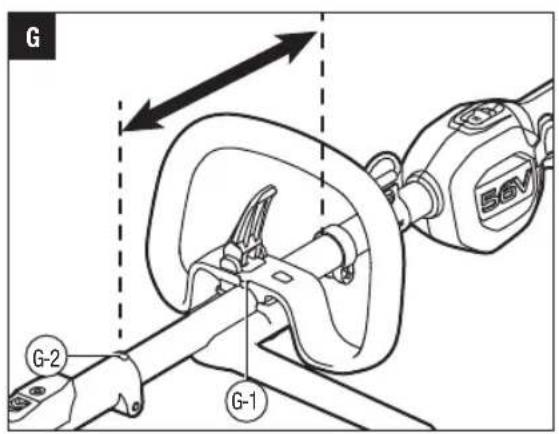
natural_image
Technical line drawing of a mechanical assembly with a rotating component and a curved housing (no text or symbols)
natural_image
Line drawing of a car steering wheel assembly with a 56V battery label (no text or symbols beyond branding)

EN
READ ALL INSTRUCTIONS!

READ OPERATOR'S MANUAL
⚠️ Residual risk! People with electronic devices, such as pacemakers, should consult their physician(s) before using this product. Operation of electrical equipment in close proximity to a heart pacemaker could cause interference or failure of the pacemaker.
WARNING: To ensure safety and reliability, all repairs and replacements should be performed by a qualified service technician.
SAFETY SYMBOLS
The purpose of safety symbols is to attract your attention to possible dangers. The safety symbols and the explanations with them deserve your careful attention and understanding. The symbol warnings do not, by themselves, eliminate any danger. The instructions and warnings they give are no substitutes for proper accident prevention measures.
WARNING: Be sure to read and understand all safety instructions in this Operator's Manual, including all safety alert symbols such as "DANGER," "WARNING," and "CAUTION" before using this tool. Failure to follow all instructions listed below may result in electric shock, fire, and/or serious personal injury.
SYMBOL MEANING
SAFETY ALERT SYMBOL: Indicates DANGER, WARNING, OR CAUTION. May be used in conjunction with other symbols or pictographs.

WARNING: The operation of any power tools can result in foreign objects being thrown into your eyes, which can result in severe eye damage. Before beginning power tool operation, always wear safety goggles or safety glasses with side shields and a full face shield when needed. We recommend a Wide Vision Safety Mask for use over eyeglasses or standard safety glasses with side shields.
SAFETY INSTRUCTIONS
This page depicts and describes safety symbols that may appear on this product. Read, understand, and follow all instructions on the machine before attempting to assemble and operate it.
 | Safety Alert | Indicates a potential personal injury hazard. |
 | Read operator's manual | To reduce the risk of injury, user must read and understand operator's manual before using this product. |
 | Wear Eye Protection | Always wear safety goggles or safety glasses with side shields and a full face shield when operating this product. |
 | CE | This product is in accordance with applicable EC directives. |
 | WEEE | Waste electrical products should not be disposed of with household waste. Take to an authorized recycler. |
 | Do Not Expose To Rain | Do not use in the rain or leave outdoors while it is raining. |
| V Volt Voltage | ||
| mm Millimeter Length or size | ||
| cm Centimeter Length or size | ||
| in. Inch Length or size | ||
| kg Kilogram Weight | ||
| lb Pound Weight | ||
 | Direct Current | Type or a characteristic of current |
GENERAL POWER TOOL SAFETY WARNINGS
WARNING: Read all safety warnings and
instructions. Failure to follow the warnings and instructions may result in electric shock, fire and/or serious injury.
Save all warnings and instructions for future reference.
The term "power tool" in the warnings refers to your mains-operated (corded) power tool or battery-operated (cordless) power tool.
WORK AREA SAFETY
- Keep work area clean and well lit. Cluttered or dark areas invite accidents.
■ Do not operate power tools in explosive atmospheres, such as in the presence of flammable liquids, petrol or dust. Power tools create sparks which may ignite the dust or fumes. - Keep children and bystanders away while operating a power tool. Distractions can cause you to lose control.
ELECTRICAL SAFETY
■ Power tool plugs must match the outlet. Never modify the plug in anyway. Do not use any adaptor plugs with earthed (grounded) power tools.
Unmodified plugs and matching outlets will reduce risk of electric shock.
- Avoid body contact with earthed or grounded surfaces, such as pipes, radiators, ranges and refrigerators. There is an increased risk of electric shock if your body is earthed or grounded.
■ Do not expose power tools to rain or wet conditions. Water entering a power tool will increase the risk of electric shock.
- Do not abuse the cord. Never use the cord for carrying, pulling or unplugging the power tool. Keep cord away from heat, oil, sharp edges or moving parts. Damaged or entangled cords increase the risk of electric shock.
- When operating a power tool outdoors, use an extension cord suitable for outdoor use. Use of a cord suitable for outdoor use reduces the risk of electric shock.
- If operating a power tool in a damp location is unavoidable, use a Ground-fault circuit interrupter protected supply. Use of GFCI reduces the risk of electric shock.
PERSONAL SAFETY
■ Stay alert, watch what you are doing and use common sense when operating a power tool. Do not use a power tool while you are tired or under the influence of drugs, alcohol, or medication. A moment of inattention while operating power tools may result in serious personal injury.
■ Use personal protective equipment. Always wear eye protection. Protective equipment such as dust mask, non-skid safety shoes, hard hat, or hearing protection used for appropriate conditions will reduce personal injuries.
■ Prevent unintentional starting. Ensure the switch is in the off-position before connecting to power source and/or battery pack, picking up or carrying the tool. Carrying power tools with your finger on the switch or energizing power tools that have the switch on invites accidents.
■ Remove any adjusting key or wrench before turning the power tool on. A wrench or a key left attached to a rotating part of the power tool may result in personal injury.
■ Do not overreach. Keep proper footing and balance at all times. This enables better control of the power tool in unexpected situations.
■ Dress properly. Do not wear loose clothing or jewelry. Keep your hair, clothing and gloves away from moving parts. Loose clothes, jewelry or long hair can be caught in moving parts.
■ If devices are provided for the connection of dust extraction and collection facilities, ensure these are connected and properly used. Use of dust devices can reduce dust-related hazards.
POWER TOOL USE AND CARE
- Do not force the power tool. Use the correct power tool for your application. The correct power tool will do the job better and safer at the rate for which it was designed.
- Do not use the power tool if the switch does not turn it on and off. Any power tool that cannot be controlled with the switch is dangerous and must be repaired.
- Disconnect the plug from the power source and/or the battery pack from the power tool before making any adjustments, changing accessories, or storing power tools. Such preventive safety measures reduce the risk of starting the power tool accidentally.
■ Store idle power tools out of the reach of children and do not allow persons unfamiliar with the power tool or these instructions to operate the power tool. Power tools are dangerous in the hands of untrained users. - Maintain power tools. Check for misalignment or binding of moving parts, breakage of parts and any other condition that may affect the power tool's operation. If damaged, have the power tool repaired before use. Many accidents are caused by poorly maintained power tools.
EN
- Keep cutting tools sharp and clean. Properly maintained cutting tools with sharp cutting edges are less likely to bind and are easier to control.
- Use the power tool, accessories and tool bits etc. in accordance with these instructions, taking into account the working conditions and the work to be performed. Use of the power tool for operations different from those intended could result in a hazardous situation.
This 56V power head PH1400E may be used with only the following EGO attachments or subsequently introduced by EGO for use with this power head:
| ATTACHMENT TYPE MODEL | NUMBER |
| Edger EA0800 | |
| Brush Cutter BCA1200 | |
| Line Trimmer STA1500 | |
| Pole Saw PSA1000 | |
| Pole Hedge Trimmer HTA2000 |
BATTERY TOOL USE AND CARE
■ Recharge only with the charger specified by the manufacturer. A charger that is suitable for one type of battery pack may create a risk of fire when used with another battery pack.
■ Use power tools only with specifically designated battery packs listed below. Use of any other battery packs may create a risk of injury and fire.
| BATTERY | CHARGER |
| BA1120E, BA2240E, BA2800, BA3360, BA4200 (BA3360 & BA4200 are not applicable when equipped with brush cutter attachment) | CH5500E, CH2100E |
- When battery pack is not in use, keep it away from other metal objects, like paper clips, coins, keys, nails, screws or other small metal objects that can make a connection from one terminal to another.
Shorting the battery terminals together may cause burns or a fire.
■ Under abusive conditions, liquid may be ejected the battery; avoid contact. If contact accidentally occurs, flush with water. If liquid contacts eyes, additionally seek medical help. Liquid ejected from the battery may cause irritation or burns.
SERVICE
■ Have your power tool serviced by a qualified repair person using only identical replacement parts.
This will ensure that the safety of the power tool is maintained.
■ If situations occur that are not covered in this manual, use care and good judgment. Contact the EGO Service Center for assistance.
SAVE THESE INSTRUCTIONS
ADDITIONAL SPECIFIC SAFETY RULES CAN BE FOUND IN THE APPLICABLE ATTACHMENT'S OPERATOR'S MANUAL
SPECIFICATIONS
| Voltage | 56 V --- |
| Weight (Without battery pack) 2.73 kg |
PACKING LIST
| PART NAME QUANTITY | |
| Power Head 1 | |
| Adjustable Front-Assist Handle | 1 |
| Shoulder Strap | 1 |
| Operator's Manual | 1 |
DESCRIPTION
KNOW YOUR POWER HEAD (Fig. A)
- Air Outlet
- Air Inlet
- Rear Handle
- Lock-off Button
- High/low-Speed Switch
- Shoulder-strap Mount Hanger
- Threshold Ring
- Adjustable Front-Assist Handle
-
Coupler
-
Shaft-Release Button
-
Wing Knob
-
Trigger
-
Battery-Release Button
-
Rubber Pad Protection
-
Latch
-
Electric Contacts
-
Ejection Mechanism
-
Shoulder Strap (special accessory)
ASSEMBLY
WARNING: If any parts are damaged or missing, do not operate this product until the parts are replaced. Use of this product with damaged or missing parts could result in serious personal injury.
WARNING: Always remove the battery pack from the product when you are assembling parts, making adjustments, cleaning, or when the product is not in use.
INSTALLING AN ATTACHMENT TO THE POWER HEAD
WARNING: Read and understand entire Operator's Manual for each optional attachment used on this power head and follow all warnings and instructions. Failure to follow all instructions could result in electric shock, fire and/or serious personal injury.
WARNING: This 56V power head PH1400E is designed to be used only with the EGO attachment models that are specified in this Operator's Manual or subsequently introduced by EGO for use with this power head. Use of other, unauthorized attachments could cause serious personal injuries or property damage.
WARNING: Never install, remove, or adjust any attachment while the power head is running or with the battery installed. Failure to stop the motor and remove the battery can cause serious personal injury. NEVER OPERATE THE POWER HEAD WITHOUT AN ATTACHMENT.
The attachment connects to the power head by means of a coupler device.
- Stop the motor and remove the battery pack.
- Loosen the wing knob.
- Remove the end cap from the attachment. Align the arrow on the attachment shaft with the arrow on the coupler and push the attachment shaft into the coupler until you hear a clear "click" sound, which indicates that the attachment shaft is mounted into place (Fig. B).
Fig. B parts description see below:
| B-1 | Attachment Shaft B-4 | Arrow on the Coupler | |
| B-2 | Arrow on the Attachment Shaft | B-5 | Shaft-Release Button |
| B-3 | Wing Knob B-6 Power-head Shaft | ||
-
Pull the shaft of the attachment to verify it is securely locked into the coupler. If not, rotate the attachment shaft from side to side in the coupler until it snaps into place.
-
Tighten the wing knob securely.
WARNING: Be certain the wing knob is fully tightened before operating equipment; check it periodically for tightness during use to avoid serious personal injury.
REMOVING THE ATTACHMENT FROM THE POWER HEAD
- Stop the motor and remove the battery pack.
- Loosen the wing knob.
- Press the shaft-release button, with the button depressed, pull or twist the attachment shift out of the coupler.
MOUNTING AND ADJUSTING THE FRONT-ASSIST HANDLE
- Stop the motor and remove the battery pack, if installed.
- Loosen the wing nut to separate the adjustable front-assist handle (Fig. C).
Fig. C parts description see below:
| C-1 | Lock Pole C-3 Front-Assist Handle |
| C-2 | Clamping Block C-4 Wing Nut |
- Push the front-assist handle onto the shaft between the threshold ring and the coupler (Fig. D).
- Insert the clamping block into the handle slot (Fig. E).
- Mount the lock pole, and pre-tighten them with the wing nut. Make sure that the front-assist handle is upwards and points toward the top of the rear handle (Fig. F).
- Adjust the front-assist handle between the threshold ring and the coupler to make sure your front arm is straight when operating and ensure that the arrow on the front-assist handle is within the limitation range marked on the coupler (Fig. G).
Fig. G parts description see below:
| G-1 | Arrow | G-2 | Limitation Range |
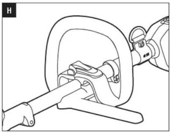
- Lock the lever of the lock pole (Fig. H).
WARNING: Never operate the tool without the front-assist handle firmly in place.
WARNING: Only fix the front-assist handle between the threshold ring and the coupler.
MOUNTING THE SHOULDER STRAP
Depress the strap hook to open it and attach it onto shoulder-strap mount hanger on the power head (Fig. 1).
EN OPERATION
WARNING: Do not allow familiarity with this product to make you careless. Remember that a careless fraction of a second is sufficient to inflict serious injury.
WARNING: Always wear eye protection. Failure to do so could result in objects being thrown into your eyes and other possible serious injuries.
WARNING: Do not use any attachments or accessories not recommended by the manufacturer of this product. The use of attachments or accessories not recommended can result in serious personal injury.
WARNING: NEVER OPERATE THE POWER HEAD WITHOUT AN ATTACHMENT.
INSTALLING/REMOVING THE BATTERY PACK
NOTE: Fully charge the battery pack before first use.
To Install
Align the battery ribs with the mounting slots and press the battery pack down until you hear a "click" (Fig. J).
Fig. J parts description see below:
J-1 Mounting Slot
J-2 Rib
To Remove
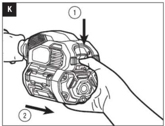
Depress the battery-release button and pull the battery pack out (Fig. K).
⚠ WARNING: To avoid serious personal injury, always remove the bat tery pack and keep hands clear of the lock-off button and trigger when carrying or transporting the tool.
STARTING/STOPPING THE POWER HEAD (Fig. L)
To Start
Press down the lock-off button and hold it in that position. Depress the trigger to turn on the power head. Different pressure on the trigger results in variable rotating speed of the power head. More pressure, higher speed.
To Stop
Release the trigger.
NOTICE: The motor runs only when the lock-off button and trigger are both pressed.
Speed Adjustment Function (Fig. L)
The power head has two speeds. Position "1" is for low speed while Position "2" for high speed. Push or pull the high/low-speed switch to choose the suitable speed during operation.
Fig. L parts description see below:
L-1 Hign/Low-Speed Switch
L-2 Lock-off Button
L-3 Trigger
MAINTENANCE
WARNING: Before inspecting, cleaning or servicing the unit, stop the motor, wait for all moving parts to stop, and remove the battery pack. Failure to follow these instructions can result in serious personal injury or property damage.
WARNING: When servicing, use only identical replacement parts. Use of any other parts can create a hazard or cause product damage. To ensure safety and reliability, all repairs, other than the items listed in these maintenance instructions, should be performed by a qualified service technician.
NOTICE: Before each use, inspect the entire product for damaged, missing, or loose parts such as screws, nuts, bolts, caps, etc. Tighten securely all fasteners and caps and do not operate this product until all missing or damaged parts are replaced. Please contact customer service or a qualified service technician.
GENERAL MAINTENANCE
Avoid using solvents when cleaning plastic parts. Most plastics are susceptible to damage from various types of commercial solvents and may be damaged by their use. Use clean cloths to remove dirt, dust, oil, grease, etc.
CLEANING THE POWER HEAD
- Stop the motor and remove the battery pack.
- Clean dirt and debris from the power head using a damp cloth with a mild detergent.
NOTICE: Do not use any strong detergents on the plastic housing or the handle. They can be damaged by certain aromatic oils such as pine and lemon.
STORING THE POWER HEAD
- Remove the battery pack from the power head before storing.
- Clean all foreign material from the power head.
- Store it in a place that is inaccessible to children.
- Keep away from corrosive agents such as garden chemicals and de-icing salts.
Protecting the environment
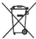
Do not dispose of electrical equipment, battery charger and batteries/rechargeable batteries into household waste!
According to the European law 2012/19/EU, electrical and electronic equipment that is no longer usable, and according to the European law 2006/66/EC, defective or used battery packs/batteries, must be collected separately.
If electrical appliances are disposed of in landfills or dumps, hazardous substances can leak into the groundwater and get into the food chain, damaging your health and well-being.
TROUBLESHOOTING
See the applicable attachment's operator's manual.
WARRANTY
EGO WARRANTY POLICY
Please visit the website egopowerplus.com for full terms and conditions of the EGO Warranty policy.
01/12/2016
EN
⚠ WAARSCHUWING: Lees alle
- Lock the lever of the lock pole (Fig. H).
SIKKERHET I ARBEIDSOMRÅDET
BRUK OG VEDLIKEHOLD AV ELEKTROVERKT∅Y
GENERELT VEDLIKEHOLD
BEZPIECZEŃSTWO W MIEJSCU PRACY
POLITYKA GWARANCYJNA EGO
CITIȚI MANUALUL DE INSTRUCTIUNI
LUGEGE KASUTUSJUHENDIT
natural_image
Line drawing of a manual chain-linking tool with a single blade and handle (no text or symbols)OPERATOR'S MANUAL
POLE SAW
ATTACHMENTT
MODEL NUMBER PSA1000
EN Pole saw attachment 5
natural_image
Illustration of a person using a tool to clean or spray a tree trunk (no text or symbols)
natural_image
Technical line drawing of a mechanical assembly with multiple components (no text or symbols)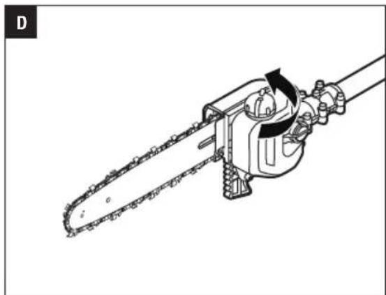
natural_image
Technical line drawing of a chain saw with gear and blade (no text or symbols)

natural_image
Line drawing of a chainsaw cutting through tree bark, with no text or symbols present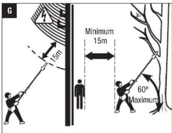
natural_image
Line drawing of a power chain saw with a lever and gear (no text or symbols)
natural_image
Illustration of hands using a power tool to adjust or install a mechanical component (no text or symbols visible)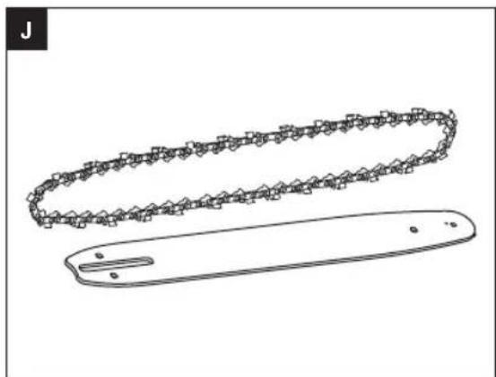
natural_image
Technical line drawing of two mechanical components: a chain-linked part and a flat plate (no text or symbols)
natural_image
Diagram of a chain with circular motion arrows indicating rotational and linear movement (no text or symbols)
natural_image
Diagram of a hand using a mechanical tool to interact with a chain, showing motion direction (no text or symbols)
natural_image
Mechanical chain diagram showing a chain with end points and an arrow indicating motion (no text or labels)

natural_image
Technical line drawing of a mechanical tool or device with no visible text or symbols
READ ALL INSTRUCTIONS!

READ OPERATOR'S MANUAL
⚠️ Residual risk! People with electronic devices, such as pacemakers, should consult their physician(s) before using this product. Operation of electrical equipment in close proximity to a heart pacemaker could cause interference or failure of the pacemaker.
WARNING: To ensure safety and reliability, all repairs and replacements should be performed by a qualified service technician.
SAFETY SYMBOLS
The purpose of safety symbols is to attract your attention to possible dangers. The safety symbols and the explanations with them deserve your careful attention and understanding. The symbol warnings do not, by themselves, eliminate any danger. The instructions and warnings they give are no substitutes for proper accident prevention measures.
WARNING: Be sure to read and understand all safety instructions in this Operator's Manual, including all safety alert symbols such as "DANGER," "WARNING," and "CAUTION" before using this tool. Failure to follow all instructions listed below may result in electric shock, fire, and/or serious personal injury.
SYMBOL MEANING
SAFETY ALERT SYMBOL: Indicates DANGER, WARNING, or CAUTION. May be used in conjunction with other symbols or pictographs.

WARNING: The operation of any power tools can result in foreign objects being thrown into your eyes, which can result in severe eye damage. Before beginning power tool operation, always wear safety goggles or safety glasses with side shields and a full face shield when needed. We recommend a Wide Vision Safety Mask for use over eyeglasses or standard safety glasses with side shields.
SAFETY INSTRUCTIONS
This page depicts and describes safety symbols that may appear on this product. Read, understand, and follow all instructions on the machine before attempting to assemble and operate it.
| Safety Alert | Indicates a potential personal injury hazard. | |
 | Read & Understand Operator's Manual | To reduce the risk of injury, user must read and understand the operator's manual before using this product. |
 | Wear Eye Protection | Always wear safety goggles or safety glasses with side shields and a full face shield when operating this product. |
 | Wear Ear Protection | Pole saw noise may damage your hearing. Always wear sound barriers (ear plugs or ear mufflers) to protect your hearing. |
 | Wear Head Protection | Wear an approved safety hard hat to protect your head. |
 | Wear Protective Gloves | Protect your hands with gloves when handling saw and saw chain. Heavy-duty, nonslip gloves improve your grip and protect your hands. |
 | Wear Safety Footwear | Wear non-slip safety footwear when using this equipment. |
 | Keep sufficient distance away from electrical power lines | To prevent electrocution, do not operate within 50 ft. (15m) of overhead electrical lines. Contact with or use near power lines may cause serious injury or electric shock resulting in death. |
 | Do Not Expose To Rain | Do not use in the rain or leave outdoors while it is raining. |
 | CE | This product is in accordance with applicable EC directives. |
EN
EN
 | WEEE | Waste electrical products should not be disposed of with household waste. Take to an authorized recycler. |
 | Noise | Guaranteed sound power level. Noise emission to the environment according to the European community's Directive. |
| V Volt Voltage | ||
| mm Millimeter Length or size | ||
| cm Centimeter Length or size | ||
| in. Inch Length or size | ||
| kg Kilogram Weight | ||
| n_0 | No Load Speed | Rotational speed, at no load |
| ... /min Per | Minute Revolutions per minute | |
| --- | Direct Current | Type or a characteristic of current |
IMPORTANT SAFETY INSTRUCTIONS
WARNING! When using electric gardening appliances, basic safety precautions should always be followed to reduce the risk of fire, electric shock, and personal injury, including the following:
READ CAREFULLY BEFORE USE
KEEP FOR FUTURE REFERENCE
DANGER! Do not operate near electrical power lines. The unit has not been designed to provide protection from electric shock in the event of contact with overhead electric lines, Consult local regulations for safe distances from overhead electric power lines and ensure that the operating position is safe and secure before operating the tool.
POLE SAW SAFETY WARNINGS
- Keep all parts of the body away from the saw chain when the pole saw is operating. Before you start the pole saw, make sure the saw chain is not contacting anything. A moment of inattention while operating pole saws may cause entanglement of your clothing or body with the chain.
- Avoid unintentional contact with the stationary saw chain or guide bar rails. These can be very sharp.
Always wear gloves and long pants or chaps when handling the pole saw, saw chain, or guide bar.
■ Always hold the pole saw with your one hand on the rear handle and your other hand on the front handle. Serious injury to the operator, helpers, and/or bystanders can result from one-handed operation. - Hold the power tool by insulated gripping surfaces only, because the saw chain may contact hidden wiring. Saw chains contacting a “live” wire may make exposed metal parts of the power tool “live” and could give the operator an electric shock.
■ Wear safety glasses and hearing protection. Further protective equipment for head, hands, legs and feet is recommended. Adequate protective clothing will reduce personal injury by flying debris or accidental contact with the saw chain. - Do not operate a pole saw in a tree. Operation of a pole saw while up in a tree may result in personal injury.
■ Always keep proper footing and operate the pole saw only when standing on fixed, secure and level surface. Slippery or unstable surfaces such as ladders may cause a loss of balance or control of the pole saw. - Never operate a pole saw that is damaged or improperly adjusted or that is not completely and securely assembled. Be sure that the saw chain stops moving when the trigger switch is released.
- Inspect the work piece for nails, wire, or other foreign objects prior to cutting.
- When cutting a limb that is under tension be alert for spring back. When the tension in the wood fibers is released the spring loaded limb may strike the operator and/or throw the pole saw out of control.
- Use extreme caution when cutting brush and saplings. The slender material may catch the saw chain and be whipped toward you or pull you off balance.
- Aggressive or abusive cutting or misuse of the pole saw can cause premature bar, chain, and/or sprocket wear, as well as broken chain or bar, leading to kickback, chain throw or the ejection of material.
- Never use the guide bar as a lever. A bent guide bar can cause premature bar, chain, and/or sprocket wear, as well as a broken chain or bar, leading to kickback, chain throw or the ejection of material.
- Carry the pole saw with two hands on the handles, with the pole saw switched off. When transporting or storing the pole saw always fit the guide bar cover. Proper handling of the pole saw will reduce the likelihood of accidental contact with the moving saw chain.
- Do not remove cut material or hold material to be cut when blades are moving. Make sure the switch is off when clearing jammed material. Saw chain continues to move after the switch is turned off. A moment of inattention while operating the pole pruner may result in serious personal injury.
■ Follow instructions for lubricating, chain tensioning and changing accessories. Improperly tensioned or lubricated chain may either break or increase the chance for kickback. Keep cutting edge sharp and clean for best performance and to reduce the risk of injury.
- Keep handles dry, clean, and free from oil and grease. Greasy, oily handles are slippery causing loss of control.
- Cut wood only. Do not use pole saw for purposes not intended. For example: do not use pole saw for cutting plastic, masonry or non-wood building materials. Use of the pole saw for operations different than intended could result in a hazardous situation.
■ Do not use the pole saw in bad weather conditions, especially when there is a risk of lightning. This decreases the risk of being struck by lightning.
■ Stop the motor and remove the battery pack whenever you leave the tool.
■ Store Idle Appliances Indoors. When not in use, appliances should be stored indoors in a dry and high or locked-up place with the battery pack removed, out of reach of children.
- Check Damaged Parts. Before further use of the product, a guard or other part that is damaged should be carefully checked to determine that it will operate properly and perform its intended function. Check for alignment of moving parts, binding of moving parts, breakage of parts, mounting, and any other condition that may affect its operation. A guard or other part that is damaged should be properly repaired or replaced by an authorized service center unless indicated elsewhere in this manual.
ADDITIONAL WARNINGS
■ Do not charge the battery pack in rain, or in wet locations.
■ Use only with EGO's battery packs and chargers.
| BATTERY PACK CHARGER | |
| BA1120E, BA2240E, BA2800 | CH2100E |
| BA3360, BA4200 | CH5500E |
■ The battery pack must be removed from the appliance before it is scrapped.
■ The battery shall be disposed of safely.
- Do not dispose of the battery in a fire. The cells may explode. Check with local codes for possible special disposal instructions.
- Do not open or mutilate the battery. Released electrolyte is corrosive and may cause damage to the eyes or skin. It may be toxic if swallowed.
CAUTION! The electrolyte is a dilute sulfuric acid that is harmful to the skin and eyes. It is electrically conductive and corrosive.
■ Exercise care in handling batteries in order not to short the battery with conducting materials such as rings, bracelets, and keys. The battery or conductor may overheat and cause burns.
■ Battery tools do not have to be plugged into an electrical outlet; therefore, they are always in operating condition. Be aware of possible hazards even when the tool is not operating. Take care when performing maintenance or service.
■ Remove the battery pack before servicing, cleaning or removing material from the tool.
- Replacement Parts - When servicing, use only identical EGO replacement parts. Use of any other accessory or attachment may increase the risk of injury.
■ Do not wash with a hose; avoid getting water in motor and electrical connections.
■ If situations occur that are not covered in this manual, use care and good judgment. Contact the EGO Service Center for assistance. - Save these instructions. Refer to them frequently and use them to instruct others who may use this tool. If you lend this tool to someone else, also lend these instructions to them to prevent misuse of the product and possible injury.
SAVE THESE INSTRUCTIONS
NOTE: SEE YOUR POWER HEAD OPERATOR'S MANUAL FOR ADDITIONAL SPECIFIC SAFETY RULES.
EN SPECIFICATIONS
| Guide Bar Length 250 mm | ||
| Chain Pitch 9.5 mm | ||
| Chain Gauge 1.1 mm | ||
| Saw Chain Type | 90PX040X(Oregon) | |
| Guide Bar Type | 104MLEA041(Oregon) | |
| Chain Oil Tank Capacity 220 ml | ||
| Weight (with chain sheath) 1.89 kg | ||
| Measured sound power level L_WA | 101.4 dB(A)K=2.36 dB(A) | |
| Sound pressure level at operator's ear L_PA | 87.0 dB(A)K=3 dB(A) | |
| Guaranteed sound power level L_WA (measured according to 2000/14/EC) | 104 dB(A) | |
| Valuation of vibration a_h : | Front-assist handle | 2.1 m/s ^2 K=1.5 m/s ^2 |
| Rear handle | 2.5 m/s ^2 K=1.5 m/s ^2 | |
■ The above parameters are tested and measured equipped with power head PH1400E.
■ The declared vibration total value has been measured in accordance with a standard test method and may be used for comparing one tool with another;
■ The declared vibration total value may also be used a preliminary assessment of exposure.
NOTICE: The vibration emission during actual use of the power tool can differ from the declared value in which the tool is used; In order to protect the operator, user should wear gloves and ear protectors in the actual conditions of use.
PACKING LIST
| PART NAME QUANTITY | |
| Pole Saw Attachment 1 | |
| Chain Sheath 1 | |
| Dual-head Wrench 1 | |
| Operator's Manual 1 |
Recommended Bar and Chain for this Pole Saw
| PART NAME MODEL NUMBER | |
| Guide Bar AG1000 | |
| Saw Chain | AC1000 |
DESCRIPTION
KNOW YOUR POLE SAW ATTACHMENT (Fig. A)
- End Cap
- Soft Sleeve
- Pole-saw Shaft
- Dual-head Wrench
- Wrench Holder
- Cover-screw
- Chain-sprocket Cover
- Extension Pole (Optional, SOLD SEPARATELY)
- Chain Sheath
- Saw Chain
- Guide Bar
- Chain-tensioning Screw
- Oil-tank Cap
- Oil Tank
- Bucking Spikes
ASSEMBLY
n⚠ WARNING: If any parts are damaged or missing, do not operate this product until the parts are replaced. Use of this product with damaged or missing parts could result in serious personal injury.
WARNING: Do not attempt to modify this product or create accessories not recommended for use with this pole saw. Any such alteration or modification is misuse and could result in a hazardous condition leading to possibly serious personal injury.
CONNECTING THE POLE SAW ATTACHMENT TO THE POWER HEAD
This pole saw attachment is designed for use with EGO 56V LITHIUM-ION Power Head PH1400E.
See "INSTALLING AN ATTACHMENT TO THE POWER HEAD" section in the power head PH1400E operator's manual.
CONNECTING THE EXTENSION POLE BETWEEN THE POWER HEAD AND THE POLE SAW ATTACHMENT (Optional)
The extension pole extends the cutting range. It should be connected between the power head and the pole saw attachment.
Follow the process in the section "CONNECTING THE POLE SAW ATTACHMENT TO THE POWER HEAD "to install and secure the extension pole between the pole saw attachment and power head (Fig. C).
WARNING: Failure to secure the attachment and power head/extension pole as instructed above could result in serious injury or death.
WARNING: Never attach or adjust any attachment while the power head is running or with the battery installed. Failure to stop the motor and remove the battery may cause serious personal injury.
OPERATION
DANGER: Never cut near power lines, electric cords, or other electric sources. If the bar and chain jams on any electrical cord or line, DO NOT TOUCH THE BAR, CHAIN OR THE ALUMINUM POLE! THEY CAN BECOME ELECTRICALLY LIVE AND MAY BE VERY DANGEROUS.
Continue to hold the pole saw by the insulated rear handle or lay it down and away from you in a safe manner. Disconnect the electrical service to the damaged line or cord before attempting to free the bar and chain from the line or cord. Contact with the bar, chain, other conductive parts of the pole saw, or live electric cords or lines could result in death by electrocution or serious injury.
WARNING: Do not allow familiarity with this product to make you careless. Remember that a careless fraction of a second is sufficient to inflict serious injury.
WARNING: Always wear eye protection, along with hearing protection. Failure to do so could result in objects being thrown into your eyes and other possible serious injuries.
Before each use, inspect the entire product for damaged, missing, or loose parts such as screws, nuts, bolts, caps, etc. Tighten securely all fasteners and caps and do not operate this product until all missing or damaged parts are replaced.
WARNING: To prevent serious personal injury, remove the battery pack from the tool before servicing, cleaning, changing attachments or removing material from the unit.
APPLICATIONS
You may use this product for the purpose listed below:
■ Limbing
Pruning
NOTICE: The tool is to be used only for its prescribed purpose. Any other use is deemed to be a case of misuse.
FILLING OILTANK WITH BAR AND CHAIN LUBRICANT
WARNING: Do not smoke or bring any fire or flame near the oil or the pole saw. Oil may spill and cause a fire.
NOTICE: The pole saw is not filled with oil at the time of purchase. It is essential to fill the tank with chain oil before use. Chain life and cutting capacity depend on optimum lubrication. The chain is automatically lubricated with chain oil during operation. Oil level should also be checked after every 20 minutes of use and refilled as needed.
- Remove the battery pack from the power head.
- Clean the oil tank cap and the area around it to ensure that no dirt falls into the oil tank.
- Place the pole saw attachment upright and rotate the oil tank cap counterclockwise to remove it (Fig. D).
- Carefully pour the bar and chain oil into the tank until it fills to the tank neck. Be careful not to let the oil spill from the opening. Wipe off any excess oil and close the oil tank cap.
NOTICE:
■ Use OREGON and chain oil for best results. It is specially designed to provide low friction and faster cuts.
■ Do not use dirty, used or other contaminated oils. Damage may occur to the bar or chain.
PREPARATION FOR CUTTING (Fig. B)
Refer to "Important Safety Instructions" earlier in this manual for appropriate safety equipment.
■ Lift the tip of the guide bar to check for any sagging in the chain. The chain is correctly tensioned when there is no sag on the underside of the guide bar and the chain is snug, but it can be turned by hand without binding. If the tension requires adjustment, refer to the "REPLACING THE BAR AND CHAIN" section in the MAINTENANCE section of this manual for adjustment instructions.
- Check the tension of the cover screw before use. If it is loose, securely tighten the cover screw by turning it clockwise.
- Check the sharpness of cutting teeth on the saw chain and make sure the chain is well lubricated.
■ Wear non-slip gloves for maximum grip and protection. LIMBING AND PRUNING
Never stand directly under the limb you are cutting. Make sure that you have a secure and balanced footing. Watch out for obstacles such as tree stumps, roots and ditches, which could cause you to trip or stumble.
- Maintain a proper grip on the unit whenever the motor is running. Hold the unit firmly with both hands.
- For safe and better operation, put on the shoulder strap across the shoulder. Adjust the shoulder strap into a comfortable operating position. Following the instructions in the section "MOUNTING THE SHOULDER STRAP" in PH1400E operator's manual to attach the shoulder strap onto the power head.
WARNING: The shoulder strap is also a quick release mechanism in hazardous situation. When an emergency occurs, take it off your shoulder immediately, no matter what way the strap is in.
TO START/STOP THE TOOL
See "STARTING/STOPPING THE POWER HEAD" section in the power head PH1400E operator's manual.
BASIC CUTTING PROCEDURE (Fig. E & F)
Follow the steps below to prevent damage to tree or shrub bark. Do not use a back-and-forth saw ing motion.
- Make a shallow first cut (1/4 of limb diameter) on the underside of the limb close to the main limb or trunk.
- Make a second cut from the top side of the limb outboard from the first cut. Continue the cut through the limb until the limb separates from the tree. Be prepared to balance the weight of the tool when the limb falls.
- Make a final cut close to trunk.
NOTICE: For second and final cuts (from top of limb or branch), hold the bucking spikes against the limb being cut (Fig. F). This will help steady the limb and make it easier to cut with light downward pressure. If you force the cut, damage to the bar, chain, or motor can result in.
- Release the trigger on the power head as soon as the cut is completed.
NOTICE: Failure to follow proper cutting procedures will result in the bar and chain binding and becoming pinched or trapped in the limb. If this should happen:
- Stop the motor and remove the battery pack.
- If the limb can be reached from the ground, lift the limb while holding the saw. This should release the "pinch" and free the saw.
- If the saw is still trapped, call a professional for assistance.
This pole saw attachment is designed for trimming small branches and limbs up to 20cm in diameter. For best results, observe the following precautions.
- Plan the cut carefully. Be aware of the direction in which the branch will fall.
WARNING: Branches may fall in unexpected directions. Do not stand directly under the branch being cut.
- The most typical cutting application is to position the unit at an angle of 60^ or less (Fig. G). As the angle of the pole saw shaft to the ground increases, the difficulty of making the first cut (from the underside of limb) increases.
- Remove long branches in several stages.
- Cut lower branches first to allow the top branch es more room to fall.
- Work slowly, keeping both hands on the saw with a firm grip. Maintain secure footing and balance.
- Do not cut from a ladder; this is extremely dangerous. Leave such operations for professionals.
- Do not make the flush cut next to the main limb or trunk until you have cut off much of limb to reduce the weight. Following proper cutting procedures will prevent stripping the bark from the main member.
- Do not use the pole saw for felling or bucking.
- To prevent electrocution, do not operate within 15m of overhead electrical lines and keep bystanders at least 15m away (Fig. G).
MAINTENANCE
WARNING: Before inspecting, cleaning or servicing the unit, stop the motor, wait for all moving parts to stop, and remove the battery pack. Failure to follow these instructions can result in serious personal injury or property damage.
WARNING: When servicing, use only identical replacement parts. Use of any other parts can create a hazard or cause product damage. To ensure safety and reliability, all repairs, other than the items listed in these maintenance instructions, should be performed by a qualified service technician.
GENERAL MAINTENANCE
Avoid using solvents when cleaning plastic parts. Most plastics are susceptible to damage from various types of commercial solvents and may be damaged by their use. Use clean cloths to remove dirt, dust, oil, grease, etc.
CLEAN THE UNIT
■ After each use, remove the battery and clean debris from the chain and guide bar with a soft brush. Wipe the pole saw surface with a clean cloth moistened with a mild soap solution.
■ Remove the chain-sprocket cover, and then use a soft brush to remove debris from the guide bar, saw chain, sprocket and chain-sprocket cover.
■ Always clean out wood chips, saw dust, and dirt from the guide bar groove when replacing the saw chain.
NOTICE: Do not use any strong detergents on the plastic housing or the handle. They can be damaged by certain aromatic oils such as pine and lemon.
REPLACING THE BAR AND CHAIN
WARNING: Never touch or adjust the chain while the motor is running. The saw chain is very sharp; always wear protective gloves when performing maintenance to the chain.
NOTICE: When replacing the guide bar and chain, always use the specified bar and chain combination listed in the "Recommended Bar and Chain for this Pole Saw" section.
Disassembling the Worn Bar and Chain
- Remove the battery, allow the pole saw to cool and tighten the oil tank cap.
- Position the pole saw attachment on its side with the chain-sprocket cover is facing upwards.
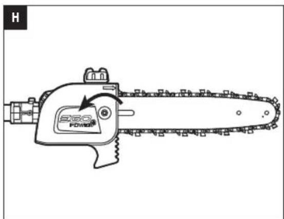
- Wear gloves. Using the dual-head wrench provided, loosen the cover screw to remove the screw and the chain-sprocket cover. Clean the chain-sprocket cover with a dry cloth and save it for reassembly (Fig. H).
- Remove the bar and chain from the mounting surface. Remove the worn chain from the bar.
NOTICE: If there is difficulty in removing the bar and chain from the mounting surface, place the pole saw upright, with one hand support the bar, to loosen the chain-tensioning screw counterclockwise with the other hand (Fig. I) and then remove the bar with the chain.
NOTICE: This is a good time to inspect the drive sprocket for excessive wear or damage.
Assembling the New Bar and Chain
- Lay the new saw chain in a loop on a flat surface and straighten any kinks (Fig. J).
- Place the chain drive links into the guide bar groove. Position the chain so there is a loop at the back of the guide bar (Fig. K).
Fig. K parts description see below:
K-1 Chain Drive Links
K-2 Guide-bar Groove
- Hold the chain in position on the guide bar and place the loop around the sprocket of the pole saw.
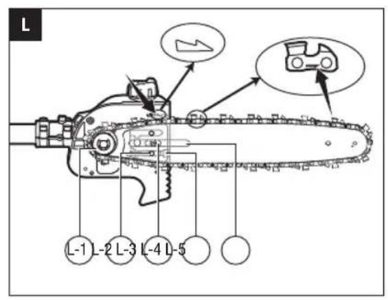
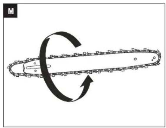
NOTICE: Small directional arrows are engraved in the saw chain. Another directional arrow is molded into the tool body (Fig. L). When looping the saw chain onto the sprocket, make sure that the direction of the arrows on the saw chain will CORRESPOND to the direction of the arrow on the tool body. If they face in opposite directions, turn over the saw chain and guide bar assembly (Fig. M).
Fig. L parts description see below:
L-1 \$procket
L-2 Tension-adjusting Pin
L-3 Alignment Bulges
L-4 Chain-tensioning Screw
L-5 Guide-bar Slot
- Place the guide bar on the mounting surface by sliding the guide bar slot over the alignment bulges, making sure that the tension adjusting pin is inserted in the lower hole in the tail of the bar (Fig. L).
NOTICE: If there is difficulty in inserting the tension adjusting pin into the hole, adjust the chain-tensioning screw properly until the tension adjusting pin is located exactly in the hole.
- Replace the chain-sprocket cover and the cover screw. Slightly tighten them.
- Remove all the slack from the chain by turning the chain-tensioning screw clockwise until the chain seats snugly against the guide bar with the drive links in the guide bar groove and lift the tip of the guide bar to check for sag. Release the tip of the guide bar and turn the chain-tensioning screw once clockwise. Repeat this process until the sag is eliminated (Fig. N).
- Hold the tip of the guide bar up and tighten the chain-sprocket-cover screw securely.
NOTICE: To extend the guide bar life, invert the bar occasionally.
NOTICE: If chain is too tight, it will not rotate. Loosen the chain-sprocket-cover screw slightly and turn the tensioning screw 1/4 turn counterclockwise. Lift the tip of the guide bar and retighten the chain-sprocket-cover screw securely. Assure that the chain will rotate without binding.
EN
ADJUSTING THE CHAIN TENSION
CAUTION: The saw chain must be properly tensioned before using.
- Stop the motor and remove the battery pack before adjusting the chain tension.
- Loosen the cover screw to finger tight.
- Turn the chain-tensioning screw clockwise to tension the chain. See the "REPLACING THE BAR AND CHAIN" section in this manual for additional information.
■ A cold chain is correctly tensioned when there is no slack on the underside of the guide bar and the chain is snug, but it can be turned by hand without binding. The chain must be re-tensioned whenever the flats on the drive links do not sit in the bar groove (Fig. 0).
■ During normal saw operation, the temperature of the chain will increase. The drive links of a correctly tensioned warm chain will hang approximately 1.3mm out of the bar groove (Fig. P).
NOTICE: New chains tend to stretch; check chain tension frequently and tension as required.
NOTICE: A chain tensioned while it is warm may be too tight upon cooling. Check the cold tension before next use.
The transmission gears in the gear case need be lubricated periodically with gear grease. Check the gear case grease level about every 50 hours of operation by removing the sealing screw on the side of the case.
If no grease can be seen on the flanks of the gear, follow the steps below to fill with gear grease up to 3/4 capacity.
Do not completely fill the transmission gears.
- Position the pole saw attachment on its side with sealing screw facing upwards (Fig. Q).
- Use the dual-head wrench provided to loosen and remove the injection screw.
- Use a grease syringe (not included) to inject some grease into the screw hole; do not exceed 3/4 capacity.
- Tighten the sealing screw after injection.
SPROCKET IN GUIDE BAR LUBRICATION
The guide bar has a sprocket at its tip. It must be lubricated weekly with chain oil injected into the lubricating hole by a grease syringe (not included) to extend the guide bar life (Fig. R). Turn the guide bar and check that the lubrication holes and chain groove are free from impurities.
Fig. R parts description see below:
| R-1 Lubricating Hole |
| R-2 Sprocket in Guide-bar Tip |
TRANSPORTING AND STORING
- Do not store or transport the pole saw attachment when it is running. Always remove the battery pack before storing or transporting.
- Always place the guide bar sheath on the guide bar and chain before storing or transporting the pole saw attachment. Use caution to avoid the sharp teeth of the chain.
- Clean the pole saw thoroughly before storing. Store the pole saw indoors, in a dry place that is locked and/or inaccessible to children and keep away from corrosive agents such as garden chemicals and de-icing salts.
- If the pole saw attachment is removed from the power head and stored separately, fit the end cap on the attachment shaft to avoid dirt getting into the coupler.
Protecting the environment

Do not dispose of electrical equipment, battery charger and batteries/rechargeable batteries into household waste!
According to the European law 2012/19/EU, electrical and electronic equipment that is no longer usable, and according to the European law 2006/66/EC, defective or used battery packs/batteries, must be collected separately.
If electrical appliances are disposed of in landfills or dumps, hazardous substances can leak into the groundwater and get into the food chain, damaging your health and well-being.
EC DECLARATION OF CONFORMITY

EN
We, EGO EUROPE GMBH
Declare that the product 56V lithium-ion cordless pole saw attachment PSA1000, equipped with power head PH1400E.
Complies with the essential health and safety requirements of the following Directives:
2006/42/EC, 2014/30/EU, 2011/65/EU, 2000/14/EC
Standards and technical specifications referred to:
EN ISO 11680-1, EN 60745-1, EN 55014-1, EN 55014-2
Measured Sound Power Level: 101.4 dB(A),
Guaranteed Sound Power Level: 104 dB(A)

Dong Jianxue
Peter Melrose Dong Jianxun
Managing Director of
EGO Europe GmbH Chervon
Quality Manager of
* (Authorized representative for CHERVON and responsible for technical documentation)
01/12/2016
EN TROUBLESHOOTING
| PROBLEM CAUSE SOLUTION | ||
| Motor does not run. | ■ The battery pack is not attached to the pole saw.■ No electrical contact between the saw and battery.■ The battery pack is depleted.■ The lock-off button is not depressed before pressing the trigger.■ The battery pack or power head is too hot.■ Saw chain is bound in the wood.■ Debris in bar groove.■ Debris in chain-sprocket cover. | ■ Attach the battery pack to the pole saw.■ Remove battery, check contacts and reinstall the battery pack.■ Charge the battery pack.■ Press down the lock-off lever and hold it, then depress the trigger to turn on the pole saw.■ Allow the battery pack or power head to cool until the temperature drops below 152°F (67°C).■ Release the trigger; remove the saw chain and guide bar from the wood, then restart the pole saw.■ Press the saw chain against the wood, move the pole saw back and forth to discharge the debris.■ Remove battery pack, then remove chain-sprocket cover and clean out debris. |
| Motor runs, but chain does not rotate. | ■ Chain does not engage drive sprocket. | ■ Remove the battery pack and reinstall the chain, making sure that the drive links on the chain are fully seated on the sprocket. |
| Pole saw does not cut properly. | ■ Insufficient chain tension.■ Dull chain.■ Chain installed backwards.■ Worn chain.■ Dry or excessively stretched chain.■ Chain not in bar groove. | ■ Remove the battery pack and readjust the chain tension, following the section “ADJUSTING THE CHAIN TENSION”.■ Sharpen the chain cutters by a qualified service technician.■ Remove the battery pack and reinstall the saw chain, following the section “REPLACING THE BAR AND CHAIN”.■ Remove the battery pack and replace the chain following the section “REPLACING THE BAR AND CHAIN”.■ Check the oil level. Refill the oil tank if necessary.■ Remove the battery pack and reinstall the saw chain, following the section “REPLACING THE BAR AND CHAIN”. |
| Bar and chain running hot and smoking. | ■ Check chain tension for over tightened condition.■ Chain oil tank is empty.■ Debris in guide bar groove. | ■ Remove the battery pack and re-tension the saw chain; see the section “ADJUSTING THE CHAIN TENSION”.■ Filling bar and chain lubricant.■ Clear the debris in the groove. |
WARRANTY
EGO WARRANTY POLICY
Please visit the website egopowerplus.com for full terms and conditions of the EGO Warranty policy.
DÉCLARATION DE CONFORMITÉ CE

Nous, EGO EUROPE GMBH
2006/42/CE, 2014/30/UE, 2011/65/UE, 2000/14/CE
2006/42/CE, 2014/30/UE, 2011/65/UE, 2000/14/CE
HET APPARAAT SCHOONMAKEN
RENG∅RING AF APPARATET
TRANSPORT OCH FÖRVARING
GENERELT VEDLIKEHOLD
DEKLARACJA ZGODNOŚCI WE
We, EGO EUROPE GMBH
2006/42/WE, 2014/30/UE, 2011/65/UE, 2000/14/WE
POLITYKA GWARANCYJNA EGO
DÔLEŽITÉ BEZPEČNOSTNÉ POKYNY
CITIȚI MANUALUL DE INSTRUCTIUNI
2006/42/CE, 2014/30/UE, 2011/65/UE, 2000/14/CE
LUGEGE KASUTUSJUHENDIT
OLULISED OHUTUSJUHISED
natural_image
Line drawing of a manual tool with a long rod and base mount (no text or symbols)OPERATOR'S MANUAL
LINE TRIMMER
ATTACHMENT
MODEL NUMBER STA1500
EN Line trimmer attachment 5
B
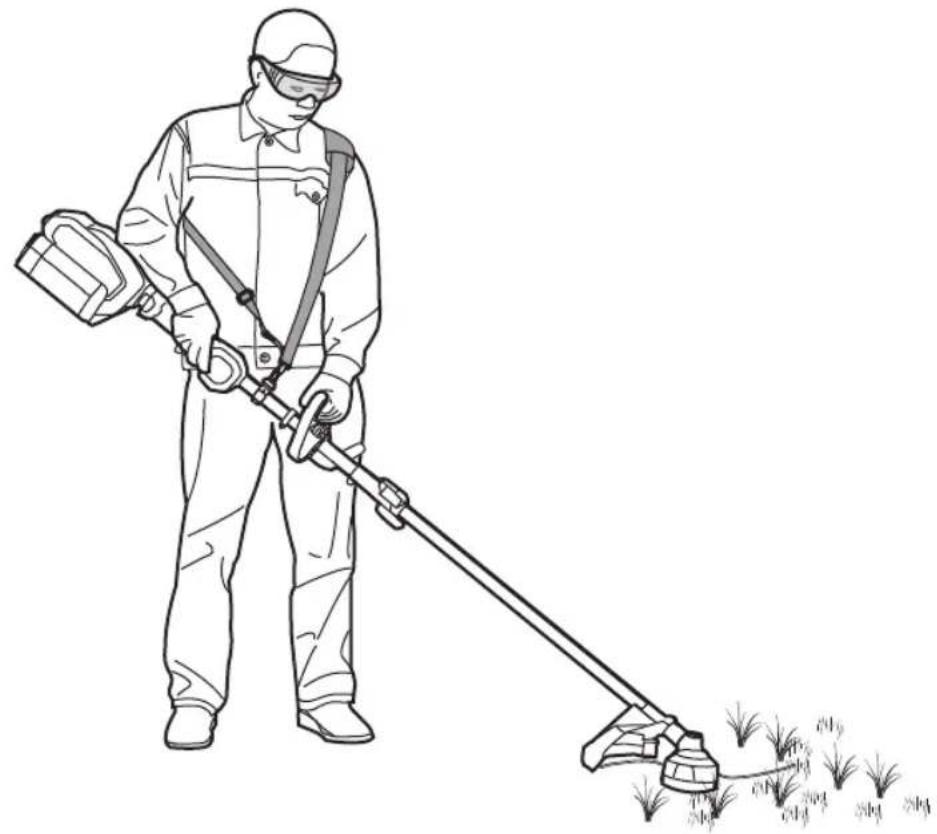
natural_image
Line drawing of a person in protective gear using a long-handled tool to spray or brush a plant (no text or symbols present)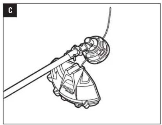
natural_image
Technical line drawing of a mechanical device with a lever and base mount (no text or symbols)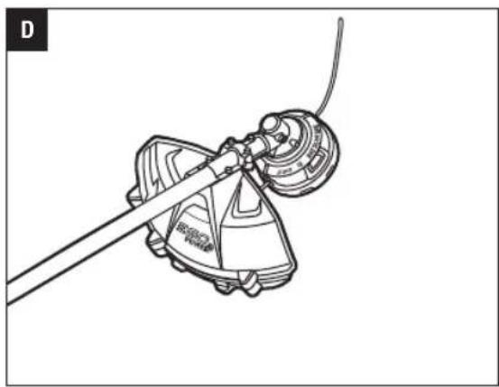
natural_image
Technical line drawing of a mechanical device with a tool and cable (no text or symbols)
natural_image
Diagram of a manual lawn saw cutting a crop with grass, showing no text or symbols
natural_image
Technical line drawing of a mechanical device with a lever and housing (no text or symbols)
natural_image
Technical line drawing of a mechanical device with an inset close-up showing a close-up detail (no text or symbols)

natural_image
Technical line drawing of a mechanical device with a highlighted component (no text or symbols)
natural_image
Technical line drawing of a mechanical device with an arrow indicating direction (no text or symbols)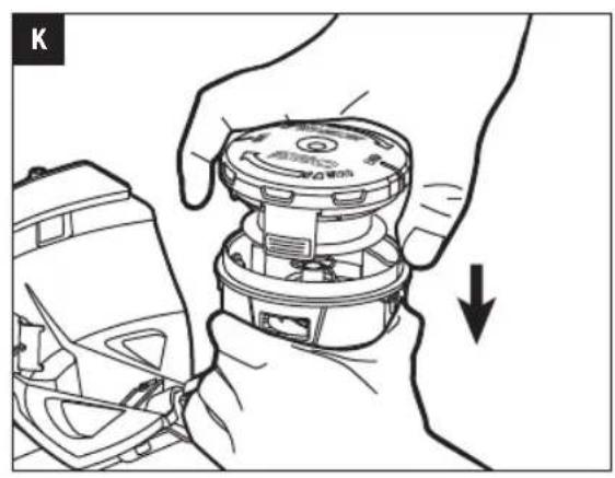
natural_image
Illustration of hands assembling a mechanical component with a downward arrow indicating motion (no text or symbols)
natural_image
Line drawing of a hand holding a circular device with an arrow indicating rotation (no text or symbols)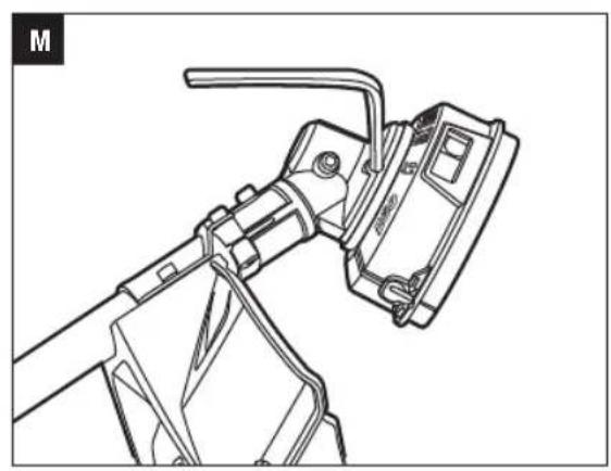
natural_image
Technical line drawing of a mechanical device with lever and bracket (no text or symbols)
natural_image
Mechanical assembly diagram showing hands using a tool to adjust a component (no text or symbols visible)
natural_image
Technical line drawing of a mechanical assembly with a tool and cable (no text or symbols)READ ALL INSTRUCTIONS!

READ OPERATOR'S MANUAL
⚠️ Residual risk! People with electronic devices, such as pacemakers, should consult their physician(s) before using this product. Operation of electrical equipment in close proximity to a heart pacemaker could cause interference or failure of the pacemaker.
⚠ WARNING: To ensure safety and reliability, all repairs and replacements should be performed by a qualified service technician.
SAFETY SYMBOLS
The purpose of safety symbols is to attract your attention to possible dangers. The safety symbols and the explanations with them deserve your careful attention and understanding. The symbol warnings do not, by themselves, eliminate any danger. The instructions and warnings they give are no substitutes for proper accident prevention measures.
WARNING: Be sure to read and understand all safety instructions in this Operator's Manual, including all safety alert symbols such as "DANGER," "WARNING," and "CAUTION" before using this tool. Failure to follow all instructions listed below may result in electric shock, fire, and/or serious personal injury.
SYMBOL MEANING
SAFETY ALERT SYMBOL: Indicates DANGER, WARNING, or CAUTION. May be used in conjunction with other symbols or pictographs.

WARNING: The operation of any power tools can result in foreign objects being thrown into your eyes, which can result in severe eye damage. Before beginning power tool operation, always wear safety goggles or safety glasses with side shields and a full face shield when needed. We recommend a Wide Vision Safety Mask for use over eyeglasses or standard safety glasses with side shields.
SAFETY INSTRUCTIONS
This page depicts and describes safety symbols that may appear on this product. Read, understand, and follow all instructions on the machine before attempting to assemble and operate it.
 | Safety Alert | Indicates a potential personal injury hazard. |
 | Read Operator's Manual | To reduce the risk of injury,user must read and understand operator's manual before using this product. |
 | Wear Eye Protection | Always wear safety goggles or safety glasses with side shields and a full face shield when operating this product. |
 | Wear hearing protection | Always wear ear protection when operating this product. |
 | Cutting Width | The Max. cutting width of line trimmer |
 | Line Diameter | The Diameter of the nylon cutting line |
 | No Cutting Blade | Do not install metal or plastic cutting blades |
 | Keep Bystanders Away | Ensure that other people and pets remain at least 15m away from the line trimmer when it is in use. |
 | Keep Bystanders Away | Ensure that other people and pets remain at least 15m away from the line trimmer when it is in use. |
 | Do Not Expose To Rain | Do not use in the rain or leave outdoors while it is raining. |
 | CE | This product is in accordance with applicable EC directives. |
 | WEEE | Waste electrical products should not be disposed of with household waste. Take to an authorized recycler. |
 | Noise | Guaranteed sound power level. Noise emission to the environment according to the European community's Directive. |
EN
EN
| V Volt Voltage | |
| mm Millimeter Length or size | |
| cm Centimeter Length or size | |
| in. Inch Length or size | |
| kg Kilogram Weight | |
IMPORTANT SAFETY INSTRUCTIONS
WARNING: When using line trimmers, basic safety precautions should always be followed to reduce the risk of fire, electric shock, and personal injury, including the following:
READ CAREFULLY BEFORE USE
KEEP FOR FUTURE REFERENCE
DANGER! Do not rely on the tool's insulation against electric shock. To reduce the risk of electrocution, never operate the machine in the vicinity of any wires or cables (power, etc.) which may carry electric current.
CAUTION! Wear appropriate personal hearing protection during use. Under some conditions and durations of use, noise from this product may contribute to hearing loss.
TRAINING
- Read the instructions carefully. Be familiar with the controls and the proper use of the machine.
■ Never allow people unfamiliar with these instructions or children to use the machine. Local regulations can restrict the age of the operator. - Keep in mind that the operator or user is responsible for accidents or hazards occurring to other people or their property.
PREPARATION
■ Never operate the machine while people, especially children, or pets are nearby.
■ Wear eye protection and stout shoes at all times while operating the machine.
■ The distance between the machine and bystanders shall be at least 15m.
OPERATION
■ Use the machine only in daylight or good artificial light.
■ Never operate the machine with damaged guards or shields or without guards or shields in place.
■ Switch on the motor only when the hands and feet are away from the cutting means.
■ Always disconnect the machine from the power supply (i.e. remove the plug from the mains or remove the disabling device).
■ whenever leaving the machine unattended;
■ before clearing a blockage;
■ before checking, cleaning or working on the machine;
■ after striking a foreign object;
■ whenever the machine starts vibrating abnormally.
■ Take care against injury to feet and hands from the cutting means.
■ Always ensure that the ventilation openings are kept clear of debris.
MAINTENANCE AND STORAGE
■ Disconnect the machine from the power supply (i.e. remove the plug from the mains or remove the disabling device) before carrying out maintenance or cleaning work.
- Use only the manufacturer's recommended replacement parts and accessories.
- Inspect and maintain the machine regularly. Have the machine repaired only by an authorized repairer.
■ When not in use, store the machine out of the reach of children.
OTHER SAFETY WARNINGS
- Avoid Dangerous Environments – Don't use trimmers in damp or wet locations.
■ Always turn the line trimmer off or remove the battery pack whenever leaving the trimmer unattended. - Don't Use In Rain.
- Keep Children Away – All visitors should be kept at a distance from work area.
- Dress Properly – Do not wear loose clothing or jewelry. They can be caught in moving parts. Use of rubber gloves and substantial footwear is recommended when working outdoors. Wear protective hair covering to contain long hair.
- Use Safety Glasses – Always use a face or dust mask if operation is dusty.
■ Use the Right Tool—Do not use the tool for any job except that for which it is intended.
- Don't Force the Trimmer – It will do the job better and with less likelihood of a risk of injury at the rate for which it was designed.
- Don't Overreach – Keep proper footing and balance at all times.
■ Stay Alert – Watch what you are doing. Use common sense. Do not operate the trimmer when you are tired.
■ Do not operate the trimmer while under the influence of alcohol or drugs.
■ Keep guards in place and in working order.
- Store Trimmer Indoors – When not in use the trimmer should be stored indoors in a dry and high or locked-up place with the battery pack removed – out of reach of children.
- Maintain Trimmer With Care – Keep the cutting attachment clean for best performance and to reduce the risk of injury. Follow instructions for changing accessories. Keep handles dry, clean, and free from oil and grease.
- Check Damaged Parts – Before further use of the trimmer, a guard or other part that is damaged should be carefully checked to determine that it will operate properly and perform its intended function. Check for alignment of moving parts, binding of moving parts, breakage of parts, mounting, and any other condition that may affect its operation. A guard or other part that is damaged should be properly repaired or replaced by an authorized service center unless indicated elsewhere in this manual.
- Clear the area to be cut before each use. Remove all objects such as rocks, broken glass, nails, wire, or line that can be thrown or become entangled in the cutting attachment. Make sure that other persons and pets are at least 15m away.
■ Before using the machine and after any impact, check for signs of wear or damage and repair as necessary.
■ Always hold the trimmer firmly, with both hands on the handles while operating. Wrap your fingers and thumbs around the handles.
- Avoid Accidentally Starting – Don't carry the trimmer with your finger on the trigger.
■ Do not operate the trimmer in petrolic or explosive atmospheres. Motors in these appliances normally spark, and the sparks might ignite fumes.
■ Damage to Trimmer – If you strike a foreign object with the trimmer or it becomes entangled, stop the tool immediately, remove the battery pack from the line trimmer, check for damage and have any damage repaired before further operation is attempted. Do not operate with a broken guard or spool.
If the equipment should start to vibrate abnormally, stop the motor, remove the battery pack from the line trimmer, and check immediately for the cause. Vibration is generally a warning of trouble. A loose head may vibrate, crack, break or come off the trimmer, which may result in serious or fatal injury. Make sure that the cutting attachment is properly fixed in position. If the head loosens after fixing it in position, replace it immediately. Never use a trimmer with a loose cutting attachment.
EN
■ Replace a cracked, damaged or worn-out cutting head immediately, even if damage is limited to superficial cracks. Such attachments may shatter at high speed and cause serious or fatal injury.
- Check the cutting attachment at regular short intervals during operation, or immediately if there is a noticeable change in cutting behavior.
■ Only use EGO authorized polymer trimmer line accessories and trimmer line that are designed for use with this machine. Although certain unauthorized attachments might be fitted to the EGO line trimmer, their use may be extremely dangerous, and/or damaging to the tools.
■ To reduce the risk of serious injury, never use wire or metal-reinforced line or other material in place of the nylon cutting lines. Pieces of wire could break off and be thrown at high speed toward the operator or bystanders.
■ To reduce the risk of injury from loss of control, never work on a ladder or on any other insecure support. Never hold the cutting attachment above waist height.
■ If situations occur that are not covered in this manual, use care and good judgment. Contact the EGO Service Center for assistance
■ Do not charge the battery pack in rain, or in wet locations.
■ Use only with EGO's battery packs and chargers.
| BATTERY | CHARGER |
| BA1120E, BA2240E, BA2800, BA3360, BA4200 | CH5500E, CH2100E |
■ The battery pack must be removed from the appliance before it is scrapped.
■ The battery shall be disposed of safely.
■ Do not dispose of the battery in a fire. The cells may explode. Check with local authorities for possible special disposal instructions.
EN
■ Do not open or mutilate the battery. Released electrolyte is corrosive and may cause damage to the eyes or skin. It may be toxic if swallowed.
■ Exercise care in handling batteries in order not to show the battery with conducting materials such as rings, bracelets, and keys. The battery or conductor may overheat and cause burns.
■ When servicing, use only identical EGO replacement parts. Use of any other accessory or attachment may increase the risk of injury.
■ Battery tools do not have to be plugged into an electrical outlet; therefore, they are always in operating condition. Be aware of possible hazards even when the tool is not operating. Take care when performing maintenance or service.
■ Do not wash with a hose; avoid getting water in motor and electrical connections.
■ Always wear substantial footwear and long trousers while operating the machine.
■ Always be sure of the footing on slopes and to walk, never run.
- Save these instructions. Refer to them frequently and use them to instruct others who may use this tool. If you loan this tool to someone else, also loan these instructions to them to prevent misuse of the product and possible injury.
SAVE THESE INSTRUCTIONS
NOTE: SEE YOUR POWER HEAD OPERATOR'S MANUAL FOR ADDITIONAL SPECIFIC SAFETY RULES.
SPECIFICATIONS
| Cutting Mechanism Bump Head | ||
| tLine Diameter | 2.4 mm nylon twist line | |
| Cutting Width 38 cm | ||
| No-Load Speed 5000/6000 min | -1 | |
| Weight (Without battery pack) 1.59 kg | ||
| Measured sound power level L_WA | 94.6 dB(A)K=1.80 dB(A) | |
| Sound pressure level at operator's ear L_PA | 83.2 dB(A)K= 3 dB(A) | |
| Guaranteed sound power level L_WA (measured according to 2000/14/EC) | 96 dB(A) | |
| Valuation of vibration a_h | Front-assist handle | 1.1 m/s ^2 K=1.5 m/s ^2 |
| Rear handle | 1.4 m/s ^2 K=1.5 m/s ^2 | |
■ The above parameters are tested and measured equipped with power head PH1400E.
■ The declared vibration total value has been measured in accordance with a standard test method and may be used for comparing one tool with another;
■ The declared vibration total value may also be used in a preliminary assessment of exposure.
NOTICE: The vibration emission during actual use of the power tool can differ from the declared value in which the tool is used; In order to protect the operator, user should wear gloves and ear protectors in the actual conditions of use.
PACKING LIST
| PART NAME QUANTITY | |
| Line Trimmer Attachment 1 | |
| Guard 1 | |
| Hex Wrench 1 | |
| Multi-Function Wrench 1 | |
| Operator's Manual 1 |
About recommended cutting line, please visit the website egopowerplus.com or refer to the EGO Product Catalogue.
DESCRIPTION
KNOW YOUR LINE TRIMMER ATTACHMENT (Fig. A)
- End Cap
- Line trimmer Shaft
- Cutting Line
- Trimmer Head (Bump Head)
- Release Tab
- Line-cutting Blade
- Guard
- Hex Wrench
- Multi-Function Wrench
WARNING: Never operate the tool without the guard firmly in place. The guard must always be on the tool to protect the user.
ASSEMBLY
WARNING: If any parts are damaged or missing, do not operate this product until the parts are replaced. Use of this product with damaged or missing parts could result in serious personal injury.
WARNING: Do not attempt to modify this product or create accessories not recommended for use with this line trimmer. Any such alteration or modification is misuse and could result in a hazardous condition leading to possibly serious personal injury.
WARNING: Do not connect to power head until assembly is complete. Failure to comply could result in accidental starting and possible serious personal injury.
MOUNTING THE GUARD
WARNING: Always wear gloves when mounting or replacing the guard. Be careful of the blade on the guard and protect your hands from being injured by the blade.
- Lift the trimmer head and face it downward; align the two mounting holes in the guard with the two bolts that are preassembled on the base of the shaft. Make sure that the internal surface of the guard faces towards the trimmer head (Fig. C).
- Lock the guard in place with the bolts and the supplied hex wrench (Fig. D).
CONNECTING THE LINE TRIMMER ATTACHMENT TO THE POWER HEAD
This line trimmer attachment is designed for use with EGO Power Head PH1400E. See "INSTALLING AN ATTACHMENT TO THE POWER HEAD" section in the power head PH1400E operator's manual.
OPERATION
WARNING: Do not allow familiarity with this product to make you careless. Remember that a careless fraction of a second is sufficient to inflict serious injury.
WARNING: Always wear eye protection, along with hearing protection. Failure to do so could result in objects being thrown into your eyes and other possible serious injuries.
APPLICATIONS
You may use this product for the purpose listed below:
■ Trimming grass and weeds from around porches, fences, and decks
NOTICE: The tool is to be used only for its prescribed purpose. Any other use is deemed to be a case of misuse.
Before each use check for damaged/worn parts
Check the trimmer head, guard and front-assist handle and replace any parts that are cracked, warped, bent, or damaged in any away.
The line-cutting blade on the edge of the guard can dull over time. It is recommended that you periodically sharpen it with a file or replace it with a new blade.
WARNING: Always wear gloves when mounting or replacing the guard or when sharpening or replacing the blade. Note the location of the blade on the guard and protect your hand from injury.
⚠ WARNING: To prevent serious personal injury, remove the battery pack from the power head before servicing, cleaning, changing attachments or removing material from the unit.
USING THE LINE TRIMMER WITH POWER HEAD
WARNING: Dress properly to reduce the risk of injury when operating this tool. Do not wear loose clothing or jewelry. Wear eye and ear/hearing protection. Wear heavy, long pants, boots and gloves. Do not wear short pants or sandals or go barefoot.
WARNING: Clear the area to be cut before each use. Remove all objects, such as rocks, broken glass, nails, wire, or string that can be thrown or become entangled in the cutting attachment. Clear the area of children, bystanders, and pets. At a minimum, keep all children, bystanders and pets at least 15m away; there still may be risk to bystanders from thrown objects. Bystanders should be encouraged to wear eye protection. If you are approached, stop the motor and cutting attachment immediately.
EN
For safe and better operation, put on the shoulder strap across the shoulder. Adjust the shoulder strap in a comfortable operating position. Hold the line trimmer with your one hand on the rear handle and your other hand on the front-assist handle. Keep a firm grip with both hands while in operation. The line trimmer should be held at a comfortable position with the rear handle about hip height. The trimmer head should be parallel to the ground such that it easily contacts the material to be cut without the operator having to bend over (Fig. B).
WARNING: The shoulder strap is also a quick release mechanism in hazardous situation. When emergency occurs, take it off from your shoulder immediately, no matter what way the strap is in.
After each use, clean the trimmer
See the MAINTENANCE section for cleaning instructions.
TO START/STOP THE TOOL
See “STARTING/STOPPING THE POWER HEAD” section in the power head PH1400E operator's manual.
ADJUSTING CUTTING LINE LENGTH
The trimmer head allows the operator to release more cutting line without stopping the motor. As line becomes frayed or worn, additional line can be released by lightly tapping the trimmer head on the ground while operating the trimmer (Fig. E).
NOTICE: Line release will become more difficult as the cutting line becomes shorter.
WARNING: Do not remove or alter the line-cutting blade assembly. Excessive line length will cause the motor to overheat and may result in serious personal injury.
LINE REPLACEMENT
NOTICE: Always use the recommended nylon cutting line with a diameter that does not exceed 2.4 mm. Using line other than that specified may cause the line trimmer to overheat or become damaged.
WARNING: Never use metal-reinforced line, wire, or rope, etc. These can break off and become dangerous projectiles.
- Remove the battery pack
- Remove the remaining cutting line, if necessary. Simply pull it out by hand.
-
Rotate the spool retainer in the direction indicated by the arrow, as necessary, to align the LOAD line on the spool retainer with the eyelets in the spool base (Fig. F).
-
Cut 5m long cutting line, about 5 times the length of the trimmer aluminium shaft. Insert the line into the mounting hole inside the eyelet (Fig. G). Push and pull the line from the other side until equal amounts of line appear on both sides of the spool.
- Press, while rotating the spool retainer in the arrow direction, to wind the line onto the spool until approximately 14cm of line is showing on each side (Fig. H).
- Push the spool retainer down while pulling on the lines to manually advance the line and to check for proper assembly of the trimmer head.
When the cutting line breaks from the line outlet or the cutting line is not released when tapping the trimmer head, follow the steps below:
- Remove the battery pack.
- Press the release tabs on the spool retainer and remove the spool retainer by pulling it straight out (Fig. I & J).
- Remove the cutting line from the spool retainer.
- With one hand holding the spool base, use the other hand to grasp the spool retainer and align the tabs on the spool retainer with the holes in the spool base (Fig. K); use your palm to press and rotate the spool retainer left and right until the tabs lock with the spool base (Fig. L).
- Following the instructions in "LINE REPLACEMENT" to reload the cutting line.
When the tool is intended to use as a brush cutter, follow the steps as Fig. M & N shown to disassemble the trimmer head.
MAINTENANCE
WARNING: Before inspecting, cleaning or servicing the unit, stop the motor, wait for all moving parts to stop, and remove the battery pack. Failure to follow these instructions can result in serious personal injury or property damage.
WARNING: When servicing, use only identical replacement parts. Use of any other parts can create a hazard or cause product damage. To ensure safety and reliability, all repairs, other than the items listed in these maintenance instructions, should be performed by a qualified service technician.
GENERAL MAINTENANCE
Avoid using solvents when cleaning plastic parts. Most plastics are susceptible to damage from various types of commercial solvents and may be damaged by their use. Use clean cloths to remove dirt, dust, oil, grease, etc.
CLEAN THE UNIT
■ Clear any grass that may have wrapped itself around the motor shaft or trimmer head.
■ Use a small brush or a small vacuum cleaner to clean the air vents on the rear housing.
■ Clean the unit using a damp cloth with a mild detergent.
■ Do not use any strong detergents on the plastic housing or the handle. They can be damaged by certain aromatic oils, such as pine and lemon, and by solvents such as kerosene. Moisture can also cause a shock hazard. Wipe off any moisture with a soft dry cloth.
The transmission gears in the gear case need be lubricated periodically with gear grease. Check the gear case grease level about every 50 hours of operation by removing the sealing screw on the side of the case.
If no grease can be seen on the flanks of the gear, follow the steps below to fill with gear grease up to 3/4 capacity.
Do not completely fill the transmission gears.
- Hold the line trimmer on its side so that the sealing screw is facing upwards (Fig. 0).
- Use the multi-function wrench provided to loosen and remove the sealing screw.
- Use a grease syringe (not included) to inject some grease into the screw hole; do not exceed 3/4 capacity.
- Tighten the sealing screw after injection.
STORING THE UNIT
■ Remove the battery pack from the trimmer.
■ Clean the tool thoroughly before storing it.
■ If the line trimmer attachment is removed from the power head and stored separately: Fit the end cap on the attachment shaft to avoid dirt getting into the coupler.
■ Store the unit in a dry, well-ventilated area, locked-up or up high, out of the reach of children. Do not store the unit on or adjacent to fertilizers, gasoline, or other chemicals.
Protecting the environment
Do not dispose of electrical equipment, battery charger and batteries/rechargeable batteries into household waste!
According to the European law 2012/19/EU, electrical and electronic equipment that is no longer usable, and according to the European law 2006/66/EC, defective or used battery packs/batteries, must be collected separately.
If electrical appliances are disposed of in landfills or dumps, hazardous substances can leak into the groundwater and get into the food chain, damaging your health and well-being.
EC DECLARATION OF CONFORMITY

We, EGO EUROPE GMBH
Declare that the product 56V lithium-ion cordless line trimmer attachment STA1500, equipped with power head PH1400E.
Complies with the essential health and safety requirements of the following Directives:
2006/42/EC, 2014/30/EU, 2011/65/EU, 2000/14/EC
Standards and technical specifications referred to:
EN 60335-1, EN 50636-2-91, EN ISO 11806-1, EN ISO 12100, EN ISO 60745-1, EN 55014-1, EN 55014-2
Measured Sound Power Level: 94.6 dB(A),
Guaranteed Sound Power Level: 96 dB(A)
Conformity assessment procedure of Annex VI is followed according 2000/14/EC.
* (Authorized representative for CHERVON and responsible for technical documentation)
01/12/2016
EN TROUBLESHOOTING
| PROBLEM CAUSE SOLUTION | ||
| Line trimmer fails to start | The battery pack is not attached to the power head.No electrical contact between the power head and the battery pack.The battery pack is depleted.The lock-off lever and trigger are not depressed simultaneously. | Attach the battery pack to the power head.Remove battery, check contacts and reinstall the battery pack until it snaps into place.Charge the battery pack with EGO chargers listed in this manual.Press down the lock-off lever and hold it, then depress the trigger to turn on the line trimmer. |
| Line trimmer stops while cutting. | The guard is not mounted on the trimmer, resulting in an overly long cutting line and motor overload.Heavy cutting line is used.The motor shaft or trimmer head is bound with grass.The motor is overloaded.The battery pack or line trimmer is too hot.The battery pack is disconnected from the tool.The battery pack is depleted. | Remove the battery pack and mount the guard on the trimmer.Use recommended nylon cutting line with diameter no greater than 0.095 in. (2.4 mm).Stop the trimmer, remove the battery, and remove the grass from the motor shaft and trimmer head.Remove the trimmer head from the grass. The motor will recover when the load is removed. When cutting, move the trimmer head in and out of the grass to be cut and remove no more than 8 inches of length in a single cut.Allow the battery pack or trimmer to cool until the temperature drops below 152°F (67°C).Re-install the battery pack.Charge the battery pack with EGO chargers listed in this manual. |
| Trimmer head will not advance line. | ■ The motor shaft or trimmer head is bound with grass.■ There is not enough line on the spool.■ The trimmer head is dirty.■ The line is tangled in the spool retainer assembly.■ The line is too short. | ■ Stop the trimmer, remove the battery, and clean motor shaft and trimmer head.■ Remove the battery and replace the cutting line; follow the section “LINE REPLACEMENT” in this manual.■ Remove the battery and clean the spool retainer assembly and spool base.■ Remove the battery, remove the line from the sp retainer and rewind; follow the section “RELOAD THE CUTTING LINE” in this manual.■ Remove the battery and pull the lines manually while alternately pressing down and releasing the trimmer head. |
| Grass wraps around trimmer head and motor housing. | ■ Cutting tall grass at ground level. | ■ Cut tall grass from the top down, removing no more than 8 inches in each pass to prevent wrapping. |
| The blade is not cutting the line. | ■ The line-cutting blade on the edge of the guard has become dull. | ■ Sharpen the line-cutting blade with a file or replace it with a new blade. |
| Cracks on the trimmer head or the spool retainer comes loose with spool base. | ■ The trimmer head is worn out. | ■ Replace the trimmer head immediately; follow the section “TRIMMER HEAD REPLACEMENT” in this manual. |
| During line replacement, the line can’t be loaded into the trimmer head properly. | ■ Spool retainer’s LOAD lines do not align with the eyelets in the spool base.■ The string line is not correctly inserted into the mounting hole in the eyelet. | ■ Rotate the spool retainer in the arrow direction to align the LOAD lines on the spool retainer with the eyelets in the spool base.■ Align the LOAD lines with the eyelets firstly, then insert the line into the mounting hole, which is located inside the eyelet. |
EN
WARRANTY
EGO WARRANTY POLICY
Please visit the website egopowerplus.com for full terms and conditions of the EGO Warranty policy.
DÉCLARATION DE CONFORMITÉ CE
CE
2006/42/CE, 2014/30/UE, 2011/65/UE, 2000/14/CE
2006/42/CE, 2014/30/UE, 2011/65/UE, 2000/14/CE
2006/42/CE, 2014/30/UE, 2011/65/UE, 2000/14/CE
ANDERE VEILIGHEIDSWAARSCHUWINGEN
| BATTERIJ | LADER |
| BA1120E, BA2240E, BA2800, BA3360, BA4200 | CH5500E, CH2100E |
DE BESCHERMING MONTEREN
HET APPARAAT SCHOONMAKEN
HET APPARAAT OPBERGEN
| BATTERI | OPLADER |
| BA1120E, BA2240E, BA2800, BA3360, BA4200 | CH5500E, CH2100E |
RENG∅RING AF APPARATET
OPBEVARING AF APPARATET
BEHOLD FOR SENERE BRUK
VEDLIKEHOLD OG LAGRING
| BATTERI | LADER |
| BA1120E, BA2240E, BA2800, BA3360, BA4200 | CH5500E, CH2100E |
GENERELT VEDLIKEHOLD
DEKLARACJA ZGODNOŚCI WE

Producent, EGO EUROPE GMBH
2006/42/WE, 2014/30/UE, 2011/65/UE, 2000/14/WE
POLITYKA GWARANCYJNA EGO
DÔLEŽITÉ BEZPEČNOSTNÉ POKYNY
INÉ BEZPEČNOSTNÉ POKYNY
CITIȚI MANUALUL DE INSTRUCTIUNI
| SET DE ACUMULATORI | ÎNCĂRCĂTOR |
| BA1120E, BA2240E, BA2800, BA3360, BA4200 | CH5500E, CH2100E |
2006/42/CE, 2014/30/UE, 2011/65/UE, 2000/14/CE
KITI SAUGOS ISPĖJIMAI
| BATERIJA | IKROVIKLIS |
| BA1120E, BA2240E, BA2800, BA3360, BA4200 | CH5500E, CH2100E |
LUGEGE KASUTUSJUHENDIT
OLULISED OHUTUSJUHISED
| AKU | LAADIJA |
| BA1120E, BA2240E, BA2800, BA3360, BA4200 | CH5500E, CH2100E |
三GO


- HEDGE TRIMMER
- ATTACHMENT
- READ ALL INSTRUCTIONS!
- READ OPERATOR'S MANUAL
- SAFETY SYMBOLS
- SYMBOL MEANING
- SAFETY INSTRUCTIONS
- EN
- IMPORTANT SAFETY INSTRUCTIONS
- READ CAREFULLY BEFORE USE
- KEEP FOR FUTURE REFERENCE
- HEDGE TRIMMER SAFETY WARNINGS
- ADDITIONAL WARNINGS
- SAVE THESE INSTRUCTIONS
- DESCRIPTION
- KNOW YOUR HEDGE TRIMMER ATTACHMENT (Fig. A)
- ASSEMBLY
- CONNECTING/REMOVING THE HEDGE TRIMMER ATTACHMENT TO THE POWER HEAD
- MOUNTING THE TIP PROTECTOR (Optional)
- OPERATION
- APPLICATIONS
- USING THE HEDGE TRIMMER WITH POWER HEAD
- PREPARATION FOR CUTTING:
- WORKING TECHNIQUES
- TO START/STOP THE TOOL
- MAINTENANCE
- GENERAL MAINTENANCE
- CLEAN THE UNIT
- SHARPENING THE CUTTING BLADE
- LUBRICATING THE BLADE
- STORING THE UNIT
- Protecting the environment
- EC DECLARATION OF CONFORMITY
- WARRANTY
- EGO WARRANTY POLICY
- DÉCLARATION DE CONFORMITÉ CE
- VEILIGHEIDSWAARSCHUWINGEN VOOR HEGGENSCHAREN
- HET APPARAAT SCHOONMAKEN
- HET APPARAAT OPBERGEN
- RENG∅RING AF APPARATET
- OPBEVARING AF APPARATET
- DRIFT
- GENERELT VEDLIKEHOLD
- DEKLARACJA ZGODNOŚCI WE
- POLITYKA GWARANCYJNA EGO
- DÔLEŽITÉ BEZPEČNOSTNÉ POKYNY
- MONTÁŽ OCHRANY HROTU (volitel'ne)
- LUGEGE KASUTUSJUHENDIT
- OLULISED OHUTUSJUHISED
- GENERAL POWER TOOL SAFETY WARNINGS
- Save all warnings and instructions for future reference.
- WORK AREA SAFETY
- ELECTRICAL SAFETY
- PERSONAL SAFETY
- POWER TOOL USE AND CARE
- BATTERY TOOL USE AND CARE
- SERVICE
- ADDITIONAL SPECIFIC SAFETY RULES CAN BE FOUND IN THE APPLICABLE ATTACHMENT'S OPERATOR'S MANUAL
- KNOW YOUR POWER HEAD (Fig. A)
- INSTALLING AN ATTACHMENT TO THE POWER HEAD
- REMOVING THE ATTACHMENT FROM THE POWER HEAD
- MOUNTING AND ADJUSTING THE FRONT-ASSIST HANDLE
- MOUNTING THE SHOULDER STRAP
- EN OPERATION
- INSTALLING/REMOVING THE BATTERY PACK
- To Install
- To Remove
- STARTING/STOPPING THE POWER HEAD (Fig. L)
- To Start
- To Stop
- Speed Adjustment Function (Fig. L)
- CLEANING THE POWER HEAD
- STORING THE POWER HEAD
- TROUBLESHOOTING
- ⚠ WAARSCHUWING: Lees alle
- SIKKERHET I ARBEIDSOMRÅDET
- BRUK OG VEDLIKEHOLD AV ELEKTROVERKT∅Y
- BEZPIECZEŃSTWO W MIEJSCU PRACY
- CITIȚI MANUALUL DE INSTRUCTIUNI
- POLE SAW SAFETY WARNINGS
- KNOW YOUR POLE SAW ATTACHMENT (Fig. A)
- CONNECTING THE POLE SAW ATTACHMENT TO THE POWER HEAD
- CONNECTING THE EXTENSION POLE BETWEEN THE POWER HEAD AND THE POLE SAW ATTACHMENT (Optional)
- FILLING OILTANK WITH BAR AND CHAIN LUBRICANT
- NOTICE:
- PREPARATION FOR CUTTING (Fig. B)
- BASIC CUTTING PROCEDURE (Fig. E & F)
- REPLACING THE BAR AND CHAIN
- Disassembling the Worn Bar and Chain
- Assembling the New Bar and Chain
- ADJUSTING THE CHAIN TENSION
- SPROCKET IN GUIDE BAR LUBRICATION
- TRANSPORTING AND STORING
- EN TROUBLESHOOTING
- TRANSPORT OCH FÖRVARING
- TRAINING
- PREPARATION
- MAINTENANCE AND STORAGE
- OTHER SAFETY WARNINGS
- NOTE: SEE YOUR POWER HEAD OPERATOR'S MANUAL FOR ADDITIONAL SPECIFIC SAFETY RULES.
- KNOW YOUR LINE TRIMMER ATTACHMENT (Fig. A)
- MOUNTING THE GUARD
- CONNECTING THE LINE TRIMMER ATTACHMENT TO THE POWER HEAD
- Before each use check for damaged/worn parts
- USING THE LINE TRIMMER WITH POWER HEAD
- After each use, clean the trimmer
- ADJUSTING CUTTING LINE LENGTH
- LINE REPLACEMENT
- ANDERE VEILIGHEIDSWAARSCHUWINGEN
- DE BESCHERMING MONTEREN
- BEHOLD FOR SENERE BRUK
- VEDLIKEHOLD OG LAGRING
- INÉ BEZPEČNOSTNÉ POKYNY
- KITI SAUGOS ISPĖJIMAI
- 三GO
Brand : EGO
Model : MHSC2002E
Category : Hedge Trimmer