
DD45 - Range hood WOLF - Free user manual and instructions
Find the device manual for free DD45 WOLF in PDF.


| Product type | Downdraft extractor hood |
| Brand | Wolf |
| Model | DD45 (ICBDD45) |
| Cutout width | 1000 mm |
| Minimum worktop depth | 638 mm |
| Electrical supply | 220-240 V AC, 50/60 Hz, dedicated 10 A circuit |
| Grounding | Required, grounded plug |
| Integrated motor | Wolf 1014 m³/h, round 152 mm vent |
| Remote motor | Max power 3 A, round 254 mm vent |
| Venting | Exterior only |
| Maximum duct run length | 12 m |
| Control module | Remote, up to 3 m from system |
| Minimum module to cooktop distance | 75 cm |
| Filters | Removable metal (grease) |
| Number of speeds | Not specified (variable control) |
| Installation | With cooktop or sealed burner countertop |
| Noise level | Not specified |
| Weight | Not specified |
| Warranty | Consult Wolf customer service |
Frequently Asked Questions - DD45 WOLF
User questions about DD45 WOLF
0 question about this device. Answer the ones you know or ask your own.
Ask a new question about this device
Download the instructions for your Range hood in PDF format for free! Find your manual DD45 - WOLF and take your electronic device back in hand. On this page are published all the documents necessary for the use of your device. DD45 by WOLF.
USER MANUAL DD45 WOLF
DOWNDRAFT VENTILATION
INSTALLATION GUIDE
GUÍA DE INSTALACIÓN
GUIDE D'INSTALLATION
DOWNDRAFT VENTILATION
Contents
2 Downdraft Ventilation
aSpecifications
4Installation
6 Troubleshooting
Features and specifications are subject to change at any time without notice. Visit wolfappliance.com/specs for the most up-to-date information.
Important Note
To ensure this product is installed and operated as safely and efficiently as possible, take note of the following types of highlighted information throughout this guide:
IMPORTANT NOTE highlights information that is especially important.
CAUTION indicates a situation where minor injury or product damage may occur if instructions are not followed.
WARNING states a hazard that may cause serious injury or death if precautions are not followed.
IMPORTANT NOTE: Save these instructions for the local electrical inspector.
Product Information
Important product information including the model and serial number are listed on the product rating plate. The rating plate is located next to the blower housing on the front side of the downdraft, below the countertop. Refer to the illustration below.
If service is necessary, contact Wolf factory certified service with the model and serial number.

Rating plate location.
WARNING
TO REDUCE THE RISK OF FIRE, ELECTRIC SHOCK, OR INJURY TO PERSONS, OBSERVE THE FOLLOWING:
a) Installation work and electrical wiring must be done by qualified person(s) in accordance with all applicable codes and standards, including fire-rated construction.
b) Sufficient air is needed for proper combustion and exhausting of gases through the flue (chimney) of fuel burning equipment to prevent back drafting. Follow the heating equipment manufacturer's guideline and safety standards, and the local code authorities.
c) When cutting or drilling into wall or ceiling, do not damage electrical wiring and other hidden utilities.
d) Ducted fans must always be vented to the outdoors.
SPECIFICATIONS
Installation Requirements
For installation with a Wolf cooktop, a minimum 638 mm deep flat countertop is required.
For installation with a sealed burner rangetop, an accessory trim kit is required. Contact your authorized Wolf dealer for details.
The remote-mounted control module can be positioned horizontally or vertically. It must be located within 3 m of the downdraft assembly and a minimum 76 mm from the edge of the cooktop or rangetop cut-out.
BLOWERS
CAUTION
For use with Wolf 1014 m ^3 /hr internal blower and remote blowers rated maximum 3 amps.
Internal and remote blower assemblies are available through your authorized Wolf dealer.
Internal blowers include a 152 mm round discharge, can be front or rear mounted and can be discharged in any direction by rotating the blower box. Remote blowers have a 254 mm round discharge and can be discharged from the front or rear.
DUCTWORK
Wolf downdrafts must be vented outside.
Consult a qualified HVAC professional for specific installation and ducting applications.
The downdraft will operate most efficiently with the fewest number of elbows and transitions and when ductwork does not exceed 12 m.
Electrical
Installation must comply with all applicable electrical codes and be properly grounded (earthed).
Locate the electrical supply as shown in the illustrations on pages 3-1. A separate circuit, servicing only this appliance is required. A ground fault circuit interrupter (GFCI) is not recommended and may cause interruption of operation.
Certain installations may require that the electrical supply be placed in an adjacent cabinet.
ELECTRICAL REQUIREMENTS
DOWNBRAFTS
Electrical Supply 220-240 V AC, 50 Hz
220 V AC, 60 Hz
Service 10 amp dedicated circuit
Receptacle grounding-type (earthed)
GROUNDING INSTRUCTIONS
This appliance must be grounded. In the event of an electrical short circuit, grounding reduces the risk of electric shock by providing an escape wire for the electric current. This appliance is equipped with a cord having a grounding wire with a grounding plug. The plug must be plugged into an outlet that is properly installed and grounded.
WARNING
Improper grounding can result in a risk of electric shock. Consult a qualified electrician if the grounding instructions are not completely understood, or if doubt exists as to whether the appliance is properly grounded.
Do not use an extension cord. If the power supply cord is too short, have a qualified electrician install an outlet near the appliance.
Downdraft
INSTALLATION WITH COOKTOP

TOP VIEW


FRONT VIEWSIDE VIEW
*102 mm back from counterlop cut-out when internal blow is rear mounted.
NOTE: Internal blower 152 mm round, side, rear or bottom discharge. Remote blower 254 mm round, rear discharge. Centerline indicates owner of download cut-out.
CUT-OUT WIDTH
MODEL W
ICBD30 699 mm
ICBDD36 851 mm
ICBDD45 1000 mm
SPECIFICATIONS
Downdraft
INSTALLATION WITH SEALED BURNER RANGETOP
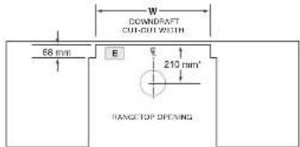
TOP VIEW


FRONT VIEWSIDE VIEW
*132 mm back from counterlop cut-out when internal blower is rear mounted.
NOTE: Internal shower 152 mm round, side, rear or bottom discharge. Remote clover 254 mm round, rear discharge.
Contactive indicators center of flowshaft cut-out.
CUT-OUT WIDTH
MODEL W
ICBDD30 699 mm
INSTALLATION
Installation
DOWNDRAFT
1 Install the top mounting brackets using the #4 sheet
metal screws provided. Refer to the illustration below.
2 install the lower mounting brackets using the 18 x 32 sheet metal screws provided, but do not tighten. The brackets will need to be adjusted once the downdraft is placed in the opening. Refer to the Illustration below.

Top mounting bracket.

Bottom leveling bracket.
TRANSITION
For internal blowers, remove the existing 254 mm round transition. Refer to the illustration below.
For remote blowers being discharged from the front, leave the 254 mm round transition in place.
For remote blowers being discharged from the rear, remove the 254 mm round transition from the front and solid cover from the rear of the downdraft, then reinstall the 254 mm transition on the rear and solid cover on the front.
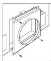
Remove transition.
INSTALLATION
Installation
INTERNAL BLOWER
To mount the internal blower on the front or rear of the downdraft:
1 Rotate the blower box so the 152 mm round discharge is properly located, then disconnect the cable from the downdraft receptacle and connect it to the blower receptacle. Refer to the illustrations below.
2 Once the blower connection is made and the discharge properly located, secure the blower to the downdraft using the four screws provided.
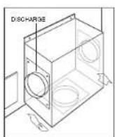

Left, right or bottom discharge.
Blower connection.
To mount the internal blower on the front of the downdraft but discharge from the rear:
1 Remove the blower from the blower box.
2 Mount the blower motor to the downdraft using the two screws provided.
a Remove the blower plug from the downdraft receptacle and insert it into the blower receptacle. Refer to the illustration below.
4 Once the plug is installed and the blower secure, install the blower box to the downdraft using the four screws provided.
5 Remove the 152 mm collar from the blower box and solid cover from the rear of the downdraft, then reinstall the 152 mm collar on the rear and solid cover on the blower box. Refer to the illustration below.

Blower mounting,

Install cover.
REMOTE BLOWER
1 Insert the electrical supply from the remote blower through the opening on the downdraft and secure using an approved cord strain relief.
2 Connect hot to brown, neutral to blue and ground to green. Refer to the illustration below.
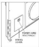
Wiring location.

Remote blower wiring.
COUNTERTOP MOUNTING
Place the downdraft in the opening, then secure the bottom brackets to the cabinet base using the wood screws provided. Once the brackets are secure, tighten the existing lower bracket screws. Refer to the illustration below.
Secure the top mounting brackets to the countertop using the wood screws provided. For solid surface countertops, silicone may be used but is not provided.
Once the top is secure, install the undercounter brackets using the screws provided then install the side covers. Refer to the illustration below.

Countertop mounting.
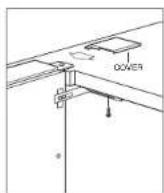
Cover installation.
INSTALLATION
Installation
CONTROL MODULE
1 Use the template provided on page 7 to mark holes for mounting screws. Drill one 40 mm in the center and two 10 mm holes for the mounting screws.
CAUTION
Verify the scale of the template if not using the installation guide shipped with the downdraft.
2 Check countertop thickness to make sure threaded studs are long enough to allow thumbs to fully engage. Thicker countertops may require the countertop be countersunk from below.
3 Place the control module on the countertop then secure using the two nuts provided. Once secure, install the ground wire and nut.
4 Use provided cable or cable designated by local codes. Connect one end of the control cable to back side of control module and other to electrical connection on front of downdraft assembly. Ensure all connections are tight.
WARNING
Do not connect to telecommunication network.
TOP COVER
Insert the downdraft plug into a grounded (earthed) receptacle, then check operation. Once operation is verified, raise the chimney and install the top trim using the three nuts provided. Verify the top trim is properly aligned with the side covers. Refer to the illustration below.
FILTERS
Remove stickers and shipping brackets and install filters. Refer to the illustration below.
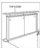
Top cover installation.

Filter installation.
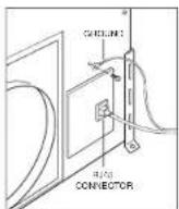
Downdraft connection.

Control module connection.
Troubleshooting
IMPORTANT NOTE: If the downdraft ventilation system does not operate properly, follow these troubleshooting steps:
- Verify electrical power is supplied to the downdraft.
- Verify proper electrical connections.
- If the downdraft does not operate properly, contact Wolf factory certified service. Do not attempt to repair the downdraft. Wolf is not responsible for service required to correct a faulty installation.
CONTROL MODULE TEMPLATE

Welt, Well & Design, Well Computer, W&S Design and the center as applied to furnace are registered trademarks and service marks of Well Appliances, Inc., Sua-Zero, S.b-Zero & Design, Coal Refrigerator, Constant Care. The Living Nitchon, Great American Nitchons The Fire Art of Kitchen Design, and Ingredients are registered trademarks and service marks of Sub Zoro, Inc. (collectively, the Company Marks). All other trademarks or registered trademarks are property of their respective owners in the United States and other countries.

Retirez la transition.
INSTALLATION
Installation
MOTEUR INTÉGRÉ
VISTA DALI'ALTO
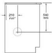
VISTA LATERALE

VISTA FRONTALE
WOLF APPLIANCE, INC.
PO BOX 44848
MADISON, WI 53744 USA
WWW.WOLFAPPLIANCE.COM
824657 REV-A 10/2013
WOLF


- DOWNDRAFT VENTILATION
- INSTALLATION GUIDE
- Contents
- Important Note
- Product Information
- WARNING
- Installation Requirements
- BLOWERS
- CAUTION
- DUCTWORK
- Electrical
- ELECTRICAL REQUIREMENTS
- GROUNDING INSTRUCTIONS
- Downdraft
- CUT-OUT WIDTH
- Installation
- INTERNAL BLOWER
- REMOTE BLOWER
- COUNTERTOP MOUNTING
- CONTROL MODULE
- TOP COVER
- FILTERS
- Troubleshooting
- MOTEUR INTÉGRÉ
Brand : WOLF
Model : DD45
Category : Range hood