
AST6 - Mill BLACK & DECKER - Free user manual and instructions
Find the device manual for free AST6 BLACK & DECKER in PDF.


| Brand | Black & Decker |
| Model | AST6 |
| Product type | Angle grinder |
| Supply voltage | 230 V AC |
| Power consumption | 701 W |
| No-load speed | 10,000 min⁻¹ |
| Disc diameter | 115 mm |
| Disc bore | 22 mm |
| Max. grinding disc thickness | 6 mm |
| Max. cutting disc thickness | 3.5 mm |
| Shaft size | M14 |
| Weight | 2.1 kg |
| Sound pressure level | 91 dB(A) (uncertainty K=3 dB(A)) |
| Sound power level | 102 dB(A) (uncertainty K=3 dB(A)) |
| Vibration (surface grinding) | 7 m/s² (uncertainty K=1.5 m/s²) |
| Vibration (cutting) | 2.5 m/s² (uncertainty K=1.5 m/s²) |
| Double insulation | Yes |
| Protection type | On/off switch with lock |
| Included accessories | Side handle, two-pin spanner, guard for grinding |
| Maintenance | Clean ventilation slots with a soft brush; clean the housing with a damp cloth; do not use solvents |
| Warranty | 24 months (domestic use) |
| Intended use | Grinding and cutting of metal and concrete |
| Compliance standards | 2006/42/EC, EN60745-1, EN60745-2-3 |
Frequently Asked Questions - AST6 BLACK & DECKER
User questions about AST6 BLACK & DECKER
0 question about this device. Answer the ones you know or ask your own.
Ask a new question about this device
Download the instructions for your Mill in PDF format for free! Find your manual AST6 - BLACK & DECKER and take your electronic device back in hand. On this page are published all the documents necessary for the use of your device. AST6 by BLACK & DECKER.
USER MANUAL AST6 BLACK & DECKER
AST6
CD105
CD110
CD115
English (Original instructions) 5
Your Black & Decker angle grinder has been designed for grinding and cutting metal and masonry using the appropriate type of cutting or grinding disc. When fitted with the appropriate guard, this tool is intended for consumer use only.
Safety instructions
General power tool safety warnings

Warning! Read all safety warnings and all instructions. Failure to follow all instructions may result in electric shock, fire and/or serious injury.
Save all warnings and instructions for future reference.
The term "power tool" in all of the warnings listed below refers to your mains operated (corded) power tool or battery operated (cordless) power tool.
- Work area safety
a. Keep work area clean and well lit. Cluttered and dark areas invite accidents.
b. Do not operate power tools in explosive atmospheres, such as in the presence of flammable liquids, gases or dust. Power tools create sparks which may ignite the dust or fumes.
c. Keep children and bystanders away while operating a power tool. Distractions can cause you to lose control.
- Electrical safety
a. Power tool plugs must match the outlet. Never modify the plug in any way. Do not use any adapter plugs with earthed (grounded) power tools. Unmodified plugs and matching outlets will reduce risk of electric shock.
b. Avoid body contact with earthed or grounded surfaces such as pipes, radiators, ranges and refrigerators. There is an increased risk of electric shock if your body is earthed or grounded.
c. Do not expose power tools to rain or wet conditions. Water entering a power tool will increase the risk of electric shock.
d. Do not abuse the cord. Never use the cord for carrying, pulling or unplugging the power tool. Keep cord away from heat, oil, sharp edges or moving parts. Damaged or entangled cords increase the risk of electric shock.
e. When operating a power tool outdoors, use an extension cord suitable for outdoor use. Use of a cord suitable for outdoor use reduces the risk of electric shock.
f. If operating a power tool in a damp location is unavoidable, use a Residual Current Device (RCD) protected supply. Use of an RCD reduces the risk of electric shock.
- Personal safety
a. Stay alert, watch what you are doing and use common sense when operating a power tool. Do not use a power tool while you are tired or under the influence of drugs, alcohol or medication. A moment of inattention while operating power tools may result in serious personal injury.
b. Use personal protective equipment. Always wear eye protection. Protective equipment such as dust mask, non-skid safety shoes, hard hat, or hearing protection used for appropriate conditions will reduce personal injuries.
c. Prevent unintentional starting. Ensure the switch is in the off-position before connecting to power source and/or battery pack, picking up or carrying the tool. Carrying power tools with your finger on the switch or energising power tools that have the switch on invites accidents.
d. Remove any adjusting key or wrench before turning the power tool on. A wrench or a key left attached to a rotating part of the power tool may result in personal injury.
e. Do not overreach. Keep proper footing and balance at all times. This enables better control of the power tool in unexpected situations.
f. Dress properly. Do not wear loose clothing or jewellery. Keep your hair, clothing and gloves away from moving parts. Loose clothes, jewellery or long hair can be caught in moving parts.
g. If devices are provided for the connection of dust extraction and collection facilities, ensure these are connected and properly used. Use of these devices can reduce dust related hazards.
- Power tool use and care
a. Do not force the power tool. Use the correct power tool for your application. The correct power tool will do the job better and safer at the rate for which it was designed.
b. Do not use the power tool if the switch does not turn it on and off. Any power tool that cannot be controlled with the switch is dangerous and must be repaired.
c. Disconnect the plug from the power source and/or the battery pack from the power tool before making any adjustments, changing accessories, or storing power tools. Such preventive safety measures reduce the risk of starting the power tool accidentally.
d. Store idle power tools out of the reach of children and do not allow persons unfamiliar with the power tool or these instructions to operate the power tool. Power tools are dangerous in the hands of untrained users.
e. Maintain power tools. Check for misalignment or binding of moving parts, breakage of parts and any other condition that may affect the power tools operation. If damaged, have the power tool repaired before use. Many accidents are caused by poorly maintained power tools.
ENGLISH
f. Keep cutting tools sharp and clean. Properly maintained cutting tools with sharp cutting edges are less likely to bind and are easier to control.
g. Use the power tool, accessories and tool bits etc. in accordance with these instructions, taking into account the working conditions and the work to be performed. Use of the power tool for operations different from those intended could result in a hazardous situation.
- Service
a. Have your power tool serviced by a qualified repair person using only identical replacement parts. This will make sure that the safety of the power tool is maintained.
Additional power tool safety warnings

Warning! Additional safety warnings for grinding, sanding, wire brushing, polishing or abrasive cutting-off operations.
- This power tool is intended to function as a grinder, sander, wire brush, polisher or cut-off tool. Read all safety warnings, instructions, illustrations and specifications provided with this power tool. Failure to follow all instructions listed below may result in electric shock, fire and/or serious injury.
◆ Operations for which the power tool was not designed may create a hazard and cause personal injury.
Do not use accessories which are not specifically designed and recommended by the tool manufacturer. Just because the accessory can be attached to your power tool, it does not assure safe operation.
- The rated speed of the accessory must be at least equal to the maximum speed marked on the power tool. Accessories running faster than their rated speed can break and fly apart.
- The outside diameter and the thickness of your accessory must be within the capacity rating of your power tool. Incorrectly sized accessories cannot be adequately guarded or controlled.
- The arbour size of wheels, flanges, backing pads or any other accessory must properly fit the spindle of the power tool. Accessories with arbour holes that do not match the mounting hardware of the power tool will run out of balance, vibrate excessively and may cause loss of control.
Do not use a damaged accessory. Before each use inspect the accessory such as abrasive wheels for chips and cracks, backing pad for cracks, tear or excess wear, wire brush for loose or cracked wires. If power tool or accessory is dropped, inspect for damage or install an undamaged accessory. After inspecting and installing an accessory and run the power tool at maximum no-load speed for one minute. Damaged accessories will normally break apart during this test time.
- Wear personal protective equipment. Depending on application, use face shield, safety goggles or safety glasses. As appropriate, wear dust mask, hearing protectors, gloves and workshop apron capable of stopping small abrasive or workpiece fragments. The eye protection must be capable of stopping flying debris generated by various operations. The dust mask or respirator must be capable of filtering particles generated by your operation. Prolonged exposure to high intensity noise may cause hearing loss.
- Keep bystanders a safe distance away from work area. Anyone entering the work area must wear personal protective equipment. Fragments of workpiece or of a broken accessory may fly away and cause injury beyond immediate area of operation.
- Hold the power tool by insulated gripping surfaces, because the sanding belt / sanding base may contact its own cord. Cutting a "live" wire may make exposed metal parts of the power tool "live" could give the operator an electric shock.
- Position the cord clear of the spinning accessory. If you lose control, the cord may be cut or snagged and your hand or arm may be pulled into the spinning accessory.
- Never lay the power tool down until the accessory has come to a complete stop. The spinning accessory may grab the surface and pull the power tool out of your control.
Do not run the power tool while carrying it at your side. Accidental contact with the spinning accessory could snag your clothing, pulling the accessory into your body.
- Regularly clean the power tool's air vents. The motor's fan will draw the dust inside the housing and excessive accumulation of powdered metal may cause electrical hazards.
Do not operate the power tool near flammable materials. Sparks could ignite these materials.
Do not use accessories that require liquid coolants. Using water or other liquid coolants may result in electrocution or shock.
Note: The above warning does not apply for power tools specifically designed for use with a liquid system.
Kickback and related warnings
Kickback is a sudden reaction to a pinched or snagged rotating wheel, backing pad, brush or any other accessory. Pinching or snagging causes rapid stalling of the rotating accessory which in turn causes the uncontrolled power tool to be forced in the direction opposite of the accessory's rotation at the point of the binding.
For example, if an abrasive wheel is snagged or pinched by the workpiece, the edge of the wheel that is entering into the pinch point can dig into the surface of the material causing the wheel to climb out or kick out. The wheel may either jump toward or away from the operator, depending on direction of the wheel's movement at the point of pinching. Abrasive wheels may also break under these conditions.
Kickback is the result of power tool misuse and/or incorrect operating procedures or conditions and can be avoided by taking proper precautions as given below.
- Maintain a firm grip on the power tool and position your body and arm to allow you to resist kickback forces. Always use auxiliary handle, if provided, for maximum control over kickback or torque reaction during start-up. The operator can control torque reactions or kickback forces, if proper precautions are taken.
◆ Never place your hand near the rotating accessory. Accessory may kickback over your hand.
Do not position your body in the area where power tool will move if kickback occurs. Kickback will propel the tool in direction opposite to the wheel's movement at the point of snagging.
Use special care when working corners, sharp edges etc. Avoid bouncing and snagging the accessory. Corners, sharp edges or bouncing have a tendency to snag the rotating accessory and cause loss of control or kickback.
Do not attach a saw chain woodcarving blade or toothed saw blade. Such blades create frequent kickback and loss of control.
Additional safety instructions for grinding and cutting-off operations
Safety warnings specific for grinding and abrasive cutting-off operations
Use only wheel types that are recommended for your power tool and the specific guard designed for the selected wheel. Wheels for which the power tool was not designed cannot be adequately guarded and are unsafe.
- The guard must be securely attached to the power tool and positioned for maximum safety, so the least amount of wheel is exposed towards the operator. The guard helps to protect operator from broken wheel fragments and accidental contact with wheel.
- Wheels must be used only for recommended applications. For example: do not grind with the side of cut-off wheel. Abrasive cut-off wheels are intended for peripheral grinding, side forces applied to these wheels may cause them to shatter.
◆ Always use undamaged wheel flanges that are of correct size and shape for your selected wheel. Proper wheel flanges support the wheel thus reducing the possibility of wheel breakage. Flanges for cut-off wheels may be different from grinding wheel flanges.
Do not use worn down wheels from larger power tools. Wheel intended for larger power tool is not suitable for the higher speed of a smaller tool and may burst.
- The guard must be securely attached to the power tool and positioned for maximum safety, so the least amount of wheel is exposed towards the operator. The guard helps to protect operator from broken wheel fragments and accidental contact with wheel. - Wheels must be used only for recommended applications. For example: do not grind with the side of cut-off wheel. Abrasive cut-off wheels are intended for peripheral grinding, side forces applied to these wheels may cause them to shatter. - Always use undamaged wheel flanges that are of correct size and shape for your selected wheel. Proper wheel flanges support the wheel thus reducing the possibility of wheel breakage. Flanges for cut-off wheels may be different from grinding wheel flanges. - Do not use worn down wheels from larger power tools. Wheel intended for larger power tool is not suitable for the higher speed of a smaller tool and may burst.
Additional safety warnings specific for abrasive cutting-off operations
Do not "jam" the cut-off wheel or apply excessive pressure. Do not attempt to make an excessive depth of cut. Over stressing the wheel increases the loading and susceptibility to twisting or binding of the wheel in the cut and the possibility of kickback or wheel breakage.
Do not position your body in line with and behind the rotating wheel. When the wheel, at the point of operation, is moving away from your body, the possible kickback may propel the spinning wheel and the power tool directly at you.
When wheel is binding or when interrupting a cut for any reason, switch off the power tool and hold the power tool motionless until the wheel comes to a complete stop. Never attempt to remove the cut-off wheel from the cut while the wheel is in motion otherwise kickback may occur. Investigate and take corrective action to eliminate the cause of wheel binding.
Do not restart the cutting operation in the workpiece. Let the wheel reach full speed and carefully re-enter the cut. The wheel may bind, walk up or kickback if the power tool is restarted in the workpiece.
◆ Support panels or any oversized workpiece to minimize the risk of wheel pinching and kickback. Large workpieces tend to sag under their own weight. Supports must be placed under the workpiece near the line of cut and near the edge of the workpiece on both sides of the wheel.
Use extra caution when making a "pocket cut" into existing walls or other blind areas. The protruding wheel may cut gas or water pipes, electrical wiring or objects that can cause kickback.
- Do not "jam" the cut-off wheel or apply excessive pressure. Do not attempt to make an excessive depth of cut. Over stressing the wheel increases the loading and susceptibility to twisting or binding of the wheel in the cut and the possibility of kickback or wheel breakage. - Do not position your body in line with and behind the rotating wheel. When the wheel, at the point of operation, is moving away from your body, the possible kickback may propel the spinning wheel and the power tool directly at you. - When wheel is binding or when interrupting a cut for any reason, switch off the power tool and hold the power tool motionless until the wheel comes to a complete stop. Never attempt to remove the cut-off wheel from the cut while the wheel is in motion otherwise kickback may occur. Investigate and take corrective action to eliminate the cause of wheel binding. - Do not restart the cutting operation in the workpiece. Let the wheel reach full speed and carefully re-enter the cut. The wheel may bind, walk up or kickback if the power tool is restarted in the workpiece. - Support panels or any oversized workpiece to minimize the risk of wheel pinching and kickback. Large workpieces tend to sag under their own weight. Supports must be placed under the workpiece near the line of cut and near the edge of the workpiece on both sides of the wheel. - Use extra caution when making a "pocket cut" into existing walls or other blind areas. The protruding wheel may cut gas or water pipes, electrical wiring or objects that can cause kickback.
ENGLISH
Safety warnings specific for sanding operations
Do not use excessively oversized sanding disc paper. Follow manufacturers recommendations, when selecting sanding paper. Larger sanding paper extending beyond the sanding pad presents a laceration hazard and may cause snagging, tearing of the disc or kickback.
Safety warnings specific for polishing operations
Do not allow any loose portion of the polishing bonnet or its attachment strings to spin freely. Tuck away or trim any loose attachment strings. Loose and spinning attachment strings can entangle your fingers or snag on the workpiece.
Safety warnings specific for wire brushing operations
- Be aware that wire bristles are thrown by the brush even during ordinary operation. Do not overstress the wires by applying excessive load to the brush. The wire bristles can easily penetrate light clothing and/or skin.
If the use of a guard is recommended for wire brushing, do not allow any interference of the wire wheel or brush with the guard. Wire wheel or brush may expand in diameter due to work load and centrifugal forces.
Safety of others
- This appliance is not intended for use by persons (including children) with reduced physical, sensory or mental capabilities, or lack of experience and knowledge, unless they have been given supervision or instruction concerning the use of the appliance by a person responsible for the their safety.
◆ Children should be supervised to ensure that they do not play with the appliance.
Vibration
The declared vibration emission values stated in the technical data and the declaration of conformity have been measured in accordance with a standard test method provided by EN 60745 and may be used for comparing one tool with another. The declared vibration emission value may also be used in a preliminary assessment of exposure.
Warning! The vibration emission value during actual use of the power tool can differ from the declared value depending on the ways in which the tool is used. The vibration level may increase above the level stated.
When assessing vibration exposure to determine safety measures required by 2002/44/EC to protect persons regularly using power tools in employment, an estimation of vibration exposure should consider, the actual conditions of use and the way the tool is used, including taking account of all parts of the operating cycle such as the times when the tool is switched off and when it is running idle in addition to the trigger time.
Labels on tools

Warning! To reduce the risk of injury, the user must read the instruction manual.

Wear safety glasses or goggles when using the tool.

Wear ear protection when using this tool.
Electrical safety

This tool is double insulated; therefore no earth wire is required. Always check that the power supply corresponds to the voltage on the rating plate.
If the supply cord is damaged, it must be replaced by the manufacturer or an authorised Black & Decker Service Centre in order to avoid a hazard.
Features
Your tool has some or all of the following features:
- On/off switch
- Side handle
- Spindle lock
- Guard
Assembly
Warning! Before assembly, make sure that the tool is switched off and unplugged.
Fitting and removing the guard (fig. A & B)
The tool is supplied with a guard intended for grinding purposes only. If the unit is intended to perform cutting off operations, a guard specific for this operation must be fitted. A suitable guard for cutting off operations part number 1004484-00 is available and can be obtained from Black & Decker service centres.
Fitting
◆ Place the tool on a table, with the spindle (5) facing up.
◆ Place the spring washer (6) over the spindle and locate it on the shoulder (7).
◆ Place the guard (4) onto the tool as shown.
Place the flange (8) over the spindle with the protruding pips towards the guard. Make sure that the holes in the flange align with the screw holes.
◆ Secure the flange with the screws (9). Make sure that the screws are fully tight and that the guard can be rotated.
Removing
◆ Use a screwdriver to remove the screws (9).
◆ Remove the flange (8), guard (4) and spring washer (7). Store these parts carefully.
Warning! Never use the tool without the guard.
Fitting the side handle
♦ Screw the side handle (2) into one of the mounting holes in the tool.
Warning! Always use the side handle.
Fitting and removing grinding or cutting discs (fig. C - E)
Always use the correct type of disc for your application. Always use discs with the correct diameter and bore size (see technical data).
Fitting
◆ Fit the guard as described above.
Place the inner flange (10) onto the spindle (5) as shown (fig. C). Make sure that the flange is correctly located on the flat sides of the spindle.
Place the disc (11) onto the spindle (5) as shown (fig. C). If the disc has a raised centre (12), make sure that the raised centre faces the inner flange.
◆ Make sure that the disc locates correctly on the inner flange.
Place the outer flange (13) onto the spindle. When fitting a grinding disc, the raised centre on the outer flange must face towards the disc (A in fig. D). When fitting a cutting disc, the raised centre on the outer flange must face away from the disc (B in fig. D).
◆ Keep the spindle lock (3) depressed and tighten the outer flange using the two-pin spanner (14) (fig. E).
Removing
♦ Keep the spindle lock (3) depressed and loosen the outer flange (13) using the two-pin spanner (14) (fig. E).
◆ Remove the outer flange (13) and the disc (11).
Fitting and removing sanding discs (fig. E & F)
For sanding, a backing pad is required. The backing pad is available from your Black & Decker dealer as an accessory.
Fitting
Place the inner flange (10) onto the spindle (5) as shown (fig. F). Make sure that the flange is correctly located on the flat sides of the spindle.
◆ Place the backing pad (15) onto the spindle.
◆ Place the sanding disc (16) onto the backing pad.
◆ Place the outer flange (13) onto the spindle with the raised centre facing away from the disc.
- Keep the spindle lock (3) depressed and tighten the outer flange using the two-pin spanner (14) (fig. E). Make sure that the outer flange is fitted correctly and that the disc is clamped tightly.
Removing
♦ Keep the spindle lock (3) depressed and loosen the outer flange (13) using the two-pin spanner (14) (fig. E).
◆ Remove the outer flange (13), the sanding disc (16) and the backing pad (15).
Residual risks
Additional residual risks may arise when using the tool which may not be included in the enclosed safety warnings. These risks can arise from misuse, prolonged use etc.
Even with the application of the relevant safety regulations and the implementation of safety devices, certain residual risks cannot be avoided. These include:
◆ Injuries caused by touching any rotating/moving parts.
◆ Injuries caused when changing any parts, blades or accessories.
◆ Injuries caused by prolonged use of a tool. When using any tool for prolonged periods make sure you take regular breaks.
◆ Impairment of hearing.
Health hazards caused by breathing dust developed when using your tool (example:- working with wood, especially oak, beech and MDF).
Use
Warning! Let the tool work at its own pace. Do not overload.
◆ Carefully guide the cable in order to avoid accidentally cutting it.
- Be prepared for a stream of sparks when the grinding or cutting disc touches the workpiece.
◆ Always position the tool in such a way that the guard provides optimum protection from the grinding or cutting disc.
Switching on and off
◆ To switch on, slide the on/off switch (1) forward. Note that the tool will continue running when you release the switch.
◆ To switch off, press the rear part of the on/off switch.
Warning! Do not switch the tool off while under load.
Hints for optimum use
- Firmly hold the tool with one hand around the side handle and the other hand around the main handle.
When grinding, always maintain an angle of approx. 15^ between the disc and the workpiece surface.
ENGLISH
Maintenance
Your Black & Decker tool has been designed to operate over a long period of time with a minimum of maintenance.
Continuous satisfactory operation depends upon proper tool care and regular cleaning.
Warning! Before performing any maintenance on corded/cordless power tools:
◆ Switch off and unplug the appliance/tool.
- Or switch off and remove the battery from the appliance/tool if the appliance/tool has a separate battery pack.
- Or run the battery down completely if it is integral and then switch off.
◆ Unplug the charger before cleaning it. Your charger does not require any maintenance apart from regular cleaning.
◆ Regularly clean the ventilation slots in your appliance/tool/charger using a soft brush or dry cloth.
◆ Regularly clean the motor housing using a damp cloth. Do not use any abrasive or solvent-based cleaner.
◆ Regularly open the chuck and tap it to remove any dust from the interior (when fitted).
Mains plug replacement (U.K. & Ireland only)
If a new mains plug needs to be fitted:
◆ Safely dispose of the old plug.
◆ Connect the brown lead to the live terminal in the new plug.
◆ Connect the blue lead to the neutral terminal.
Warning! No connection is to be made to the earth terminal.
Follow the fitting instructions supplied with good quality plugs.
Recommended fuse: 13 A.
Protecting the environment
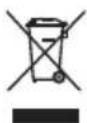
Separate collection. This product must not be disposed of with normal household waste.
Should you find one day that your Black & Decker product needs replacement, or if it is of no further use to you, do not dispose of it with household waste. Make this product available for separate collection.

Separate collection of used products and packaging allows materials to be recycled and used again. Re-use of recycled materials helps prevent environmental pollution and reduces the demand for raw materials.
Local regulations may provide for separate collection of electrical products from the household, at municipal waste sites or by the retailer when you purchase a new product.
Black & Decker provides a facility for the collection and recycling of Black & Decker products once they have reached the end of their working life. To take advantage of this service please return your product to any authorised repair agent who will collect them on our behalf.
You can check the location of your nearest authorised repair agent by contacting your local Black & Decker office at the address indicated in this manual. Alternatively, a list of authorised Black & Decker repair agents and full details of our after-sales service and contacts are available on the Internet at: www.2helpU.com.
Technical data
| AST6 TYPE 4 CD105 TYPE 4 | ||
| Voltage Vac 230 230 | ||
| Power input W 701 701 | ||
| No-load speed min | -1 | 10,000 10,000 |
| Disc diameter mm 115 115 | ||
| Disc bore mm 22 22 | ||
| Max disc thickness | ||
| grinding discs mm 6 6 | ||
| cutting discs | mm 3.5 | 3.5 |
| Spindle size | mm M14 | M14 |
| Weight | kg 2.1 | 2.1 |
CD110 TYPE 4 CD115 TYPE 4
| Voltage Vac 230 230 | ||
| Power input W 701 710 | ||
| No-load speed min | -1 | 10,000 10,000 |
| Disc diameter mm 100 115 | ||
| Disc bore mm 16 22 | ||
| Max disc thickness | ||
| grinding discs mm 6 6 | ||
| cutting discs | mm 3.5 | 3.5 |
| Spindle size | mm M10 | M14 |
| Weight | kg 2.1 | 2.1 |
Level of sound pressure according to EN60745:
Sound pressure ( L_pA ) 91 dB(A), uncertainty (K) 3 dB(A)
Sound power (LWA) 102 dB(A), uncertainty (K) 3 dB(A)
Vibration total values (triax vector sum)
according to EN 60745:
Surface grinding ( a_h,AG ) 7 m/s ^2 , uncertainty (K) 1.5 m/s ^2
Cutting-off ( a_h ) 2.5 m/s ^2 , uncertainty (K) 1.5 m/s ^2
EC declaration of conformity MACHINERY DIRECTIVE

AST6, CD105, CD110, CD115
Black & Decker declares that these products described under "technical data" are in compliance with: 2006/42/EC, EN60745-1, EN60745-2-3
These products also comply with Directive 2004/108/EC and 2011/65/EU.
For more information, please contact Black & Decker at the following address or refer to the back of the manual.
The undersigned is responsible for compilation of the technical file and makes this declaration on behalf of Black & Decker.
Kevin Hewitt
Vice-President Global Engineering
Black & Decker Europe, 210 Bath Road, Slough, Berkshire, SL1 3YD
United Kingdom
22/02/2012
Guarantee
Black & Decker is confident of the quality of its products and offers an outstanding guarantee. This guarantee statement is in addition to and in no way prejudices your statutory rights. The guarantee is valid within the territories of the Member States of the European Union and the European Free Trade Area.
If a Black & Decker product becomes defective due to faulty materials, workmanship or lack of conformity, within 24 months from the date of purchase, Black & Decker guarantees to replace defective parts, repair products subjected to fair wear and tear or replace such products to make sure of the minimum inconvenience to the customer unless:
• The product has been used for trade, professional or hire purposes.
• The product has been subjected to misuse or neglect.
• The product has sustained damage through foreign objects, substances or accidents.
• Repairs have been attempted by persons other than authorised repair agents or Black & Decker service staff.
To claim on the guarantee, you will need to submit proof of purchase to the seller or an authorised repair agent. You can check the location of your nearest authorised repair agent by contacting your local Black & Decker office at the address indicated in this manual. Alternatively, a list of authorised Black & Decker repair agents and full details of our after-sales service and contacts are available on the Internet at:
www.2helpU.com
Please visit our website www.blackanddecker.co.uk to register your new Black & Decker product and to be kept up to date on new products and special offers. Further information on the Black & Decker brand and our range of products is available at www.blackanddecker.co.uk.
DEUTSCH
Vice-President Global Engineering
Black & Decker Europe, 210 Bath Road, Slough,
Berkshire, SL1 3YD
Großbritannien
22/03/2012
Garantie
Vice-President Global Engineering
Black & Decker Europe, 210 Bath Road, Slough,
Berkshire, SL1 3YD
Regno Unito
22/03/2012
ITALIANO
Garanzia
Vice-President Global Engineering
Black & Decker Europe, 210 Bath Road, Slough,
Berkshire, SL1 3YD
Verenigd Koninkrijk
22/03/2012
Garantie
Vice-President Global Engineering Spennymoor, County Black & Decker Europe, 210 Bath Road, Slough, Reino Berkshire, SL1 3YD Unido 22/03/2012
Garantia
Vice-President Global Engineering
Black & Decker Europe, 210 Bath Road, Slough,
Berkshire, SL1 3YD
Storbritannien
22/03/2012
Garanti
Sikkerhetsadvarsler for slipping
Vice-President Global Engineering
Black & Decker Europe, 210 Bath Road, Slough,
Berkshire, SL1 3YD
Storbritannia
22/03/2012
Garanti
Black & Decker er trygg på kvaliteten til sine produkter og tilbyr en enestående garanti. Denne garantierklæringen kommer i tillegg til dine lovbestemte rettigheter, og er ikke i konflikt med disse. Garantien er gyldig i EU- og EFTA-medlemsstatene.
Vice-President Global Engineering
Black & Decker Europe, 210 Bath Road, Slough, Berkshire, SL1 3YD
Storbritannien
22/03/2012
Garanti
Vice-President Global Engineering
Black & Decker Europe, 210 Bath Road, Slough,
Berkshire, SL1 3YD
Iso-Britannia
22/03/2012
Takuu
©
ENGLISH
Do not forget to register your product! www.blackanddecker.co.uk/productregistration
Register your product online at www.blackanddecker.co.uk/productregistration or send your name, surname and product code to Black & Decker in your country.
DEUTSCH
www.blackanddecker.pt/productregistration
- Safety instructions
- ENGLISH
- Additional power tool safety warnings
- Kickback and related warnings
- Safety warnings specific for grinding and abrasive cutting-off operations
- Safety warnings specific for sanding operations
- Safety warnings specific for polishing operations
- Safety warnings specific for wire brushing operations
- Safety of others
- Vibration
- Labels on tools
- Electrical safety
- Features
- Assembly
- Fitting and removing the guard (fig. A & B)
- Fitting
- Removing
- Fitting the side handle
- Fitting and removing grinding or cutting discs (fig. C - E)
- Fitting and removing sanding discs (fig. E & F)
- Residual risks
- Use
- Switching on and off
- Hints for optimum use
- Maintenance
- Mains plug replacement (U.K. & Ireland only)
- Protecting the environment
- EC declaration of conformity MACHINERY DIRECTIVE
- AST6, CD105, CD110, CD115
- Guarantee
- www.2helpU.com
- DEUTSCH
- Garantie
- ITALIANO
- Garanzia
- Garantia
- Garanti
- Sikkerhetsadvarsler for slipping
- Takuu
- Do not forget to register your product! www.blackanddecker.co.uk/productregistration
- www.blackanddecker.pt/productregistration
Brand : BLACK & DECKER
Model : AST6
Category : Mill