
EFK 3290-92 X - Range hood GRAM - Free user manual and instructions
Find the device manual for free EFK 3290-92 X GRAM in PDF.

| Product Type | Range Hood |
| Brand | Gram |
| Model | EFK 3290-92 X |
| Color | Stainless Steel |
| Width | 90 cm (35.4 inches) |
| Depth | 50 cm (19.7 inches) |
| Height | 75-130 cm (adjustable) |
| Net Weight | 15 kg |
| Power Supply | 220-240 V / 50 Hz |
| Motor Power | 250 W |
| Extraction Rate (Max) | 720 m³/h |
| Noise Level (Max) | 65 dB(A) |
| Number of Speeds | 3 + Intensive |
| Control Type | Electronic Touch Control |
| Lighting | 2 x 1.5 W LED |
| Filter Type | Aluminum Grease Filter + Optional Carbon Filter |
| Installation Type | Wall-mounted Chimney |
| Energy Class | A (EU) (Estimated) |
| Safety Features | Auto Shut-off Timer, Overheat Protection |
| Maintenance | Grease filter: Clean monthly; Carbon filter: Replace every 3-6 months |
| Spare Parts Availability | Filters, bulbs available via Gram service |
Frequently Asked Questions - EFK 3290-92 X GRAM
User questions about EFK 3290-92 X GRAM
0 question about this device. Answer the ones you know or ask your own.
Ask a new question about this device
Download the instructions for your Range hood in PDF format for free! Find your manual EFK 3290-92 X - GRAM and take your electronic device back in hand. On this page are published all the documents necessary for the use of your device. EFK 3290-92 X by GRAM.
USER MANUAL EFK 3290-92 X GRAM
Before using the appliance, please carefully read this manual!
BETJENINGSVEJLEDNING - EMFANG
natural_image
Illustration of a hand pressing a button on a device (no text or symbols visible)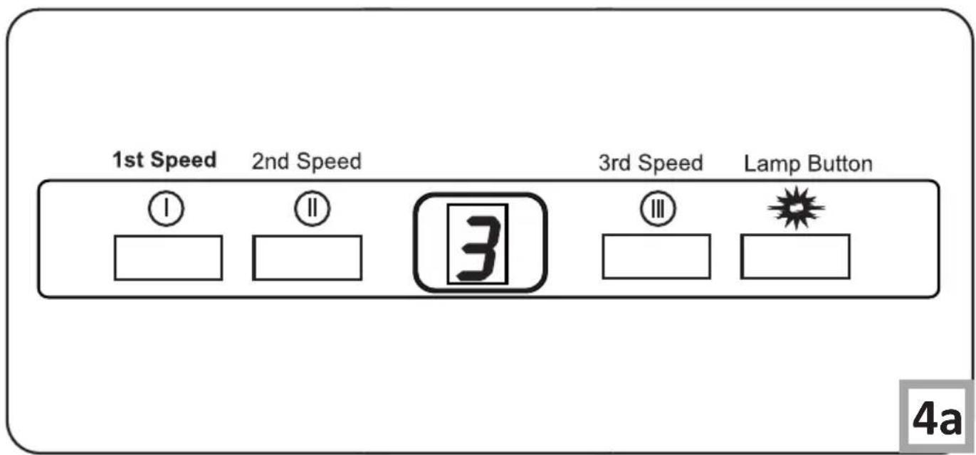
natural_image
Technical illustration of a mechanical assembly with a frame and fan components, showing rotational motion (no text or symbols)THANK YOU FOR PURCHASING AN GRAM APPLIANCE
DEAR CUSTOMER!
You are now a user of a kitchen extractor hood. This hood has been designed and manufactured specially with a view to satisfying your expectations and it will certainly constitute a fitting element of a modern kitchen. The modern structural solutions and the newest technologies used in production of this hood guarantee its high effectiveness and good appearance.
Please read these instructions carefully before installing the hood. They will help you avoid mistakes during installation and operation of the hood.
We wish you a lot of satisfaction from choosing our kitchen extractor hood.
Symbols appearing in these instructions have the following meaning:

Important information concerning proper operation of the appliance and your personal safety.

Risks resulting from improper operation of the appliance. Activities that must be performed by a qualified technician.

Tips on how to use the appliance.

Information on how to protect the environment.

This indicates actions than must not be performed by the user.
TABLE OF CONTENTS
GUIDELINES CONCERNING THE SAFETY OF USE 5
INSTALLATION
8
OPERATION
AND
MAINTENANCE
13
ENVIRONMENTAL
PROTECTION
15

The appliance is intended for household use only.
The manufacturer reserves the right to introduce changes which do not affect the operation of the appliance.

●The manufacturer will accept no responsibility for any damage due to installation or operation not conforming to these instructionsi
● Cooker hood is designed to remove cooking odours. Do not use cooker hood for other purposes.
- Connect the cooker hood operating in extraction mode to a suitable ventilation duct (do NOT connect the cooker to smoke or flue gas ducts, which are in use). It requires installation of the air extraction duct to the outside. The duct length (typically 120 or 150mm in diameter) should not exceed 4-5 m. The air exhaust duct is also required for telescopic and under furniture cooker hoods operating in air recirculation mode.
● Cooker hood operating in air recirculation mode requires the installation of an activated charcoal filter. In this case, installing an extractor duct is not required, however it is recommended to install an air guide vane. (chimney cooker hoods only).


●The cooker hood features independent lighting and exhaust fan that can be operated at one of several speeds.
- Depending on the type, the hood is designed to be permanently attached to a vertical wall over a gas or electric stove (chimney and universal hoods); on the ceiling over a gas or electric stove (island hoods); on the vertical built in furniture over a gas or electric stove (telescopic and built-in hoods). Before installing, make sure that the wall/ceiling structure is strong enough to suspend the hood. Some hoods are very heavy.
●For details of the installation distance above an electric hob please refer to product technical sheet. If the installation instructions of the gas cooker specify a greater distance, this must be taken into account (Fig. 1a).
- Do not leave an open flame under the hood. When the pots are removed from the burner, set the minimum flame. Always make sure that the flame does not ex-

tend outside the pot, because it causes unwanted loss of energy and a dangerous concentration of heat.
●Any food cooked in fat shall be constantly monitored, since overheated fat can ignite very easily.
- Pull the plug of the power cord from a wall socket before any filter cleaning or repair operation.
●The textile grease filter should be replaced, and the aluminium filter should be cleaned at least every one month in connection with the existing fire danger (saturated fat is very flammable).
- If any other non-electric devices are used in the same room as the hood (e.g. liquid fuel ovens, flow-through or volumetric water heaters), it is necessary to provide appropriate ventilation (air supply). Safe operation is possible when during simultaneous operation of the hood and combustion devices dependent on air supply the negative pressure of not more than 0.004 milibar is


maintained at the location of these devices inside the room (this point does not apply when the hood is used as an odour absorber).
●Do not lean on hood
●The hood should be frequently cleaned inside and on the outside surfaces (at least once a month). See “Cleaning section” in this manual.
- If the power wire gets broken, it should be replaced with a new one in a specialist repair shop.
- If the power wire gets broken, it should be replaced with a new one in a specialist repair shop.
●Make sure the appliance can be easily disconnected from the mains, either by pulling the plug out of the mains socket, or by switching the two-pole switch off.
●This appliance is not intended for use by persons (including children) with reduced physical, sensory or mental capabilities, or lack of experience and knowledge, unless they have been given supervision or instruction concerning use of the appliance by a person responsible for their safety.
●Children should be su-

pervised to ensure that they do not play with the appliance.
- Check if the voltage indicated on the rating plate corresponds to the local power supply parameters.
●Before installing unwind and straighten the power cord.
●Warning! The packaging materials (polyethylene bags, small pieces of foamed poly-
styrene etc.) should be kept away from children while unpacking.
NOTE: Before connecting the hood to the mains power supply always check that the power cord is properly installed and is not trapped by the appliance. It is recommended to make sure the hood operates correctly before installation.
INSTALLATION
Elements
Kitchen hood consists of the following elements (Pic. 2a):
1-Internal chimney
2-External chimney
3-Control panel
4-Lighting
Installation
Step-by-step appliance installation is shown on page 9-12
Setting the air extractor mode of operation of the hood
In the extractor mode air is discharged to the outside by a special conduit. In that setting any carbon filters shall be removed. The hood should be connected to the opening discharging air to the outside by means of a rigid or flexible conduit of
120 mm diameter, which should be purchased in a shop selling installation materials.
A qualified installer should be commissioned to make the connection.
Setting the odour absorber mode of operation of the hood
In this option filtered air returns to the room through openings in the front of the hood. In this setting it is necessary to install the carbon filter. It is recommended to install the air guide (availability depending on model).
Fan speeds
The lowest and medium speeds should be used under normal conditions and with low concentration of fumes. The maximum speed should be used in case of high concentration of kitchen fumes, e.g. during frying or grilling.
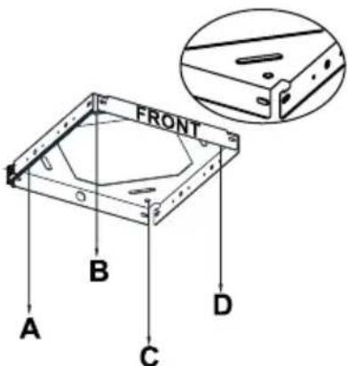
A) Installation of ceiling connection plate
Front sticker (picture 3) on ceiling connection plate and control panel of chimney hood should have the same direction.
1) Drill 10mm holes from A,B,C,D points.
2)Drive 10mm wall plugs in to A,B,C,D holes.
3) Fix ceiling connection plate to ceiling by using
4 screws (5,5 x 45). Wall plugs, screws and ceiling connection plate are given with chimney hood - picture 3
Pic. 3
B) Installation of cornerpieces:
Front sticker(picture 4) shows where front side of chimney hood should be installed. Front cornerpieces should be left and right directions. Back cornerpieces should be extroverted. Screw 4 cornerpieces to motor block. Hanging bar should have same directions with ceiling connection plate. Regulating the length of chimney hood with these cornerpieces.
C) Installation of chimneys to motor cabinet:
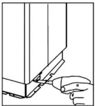
Please put internal chimney in extarnal chimney. For temporary connection between chimneys please use a screw on motor cabinet. (So chimneys will not drop while you install motor cabinet to ceiling connection plate.) Mount the chimneys on this screw. (Screw holes of internal chimney should befit the side of motor cabinet.) Picture 5, 5a, 5b
natural_image
Line drawing of a hand holding a tool interacting with a mechanical component (no text or symbols)Pic. 5
Front bracket connection, left and right up front
Back bracket connection, up-front
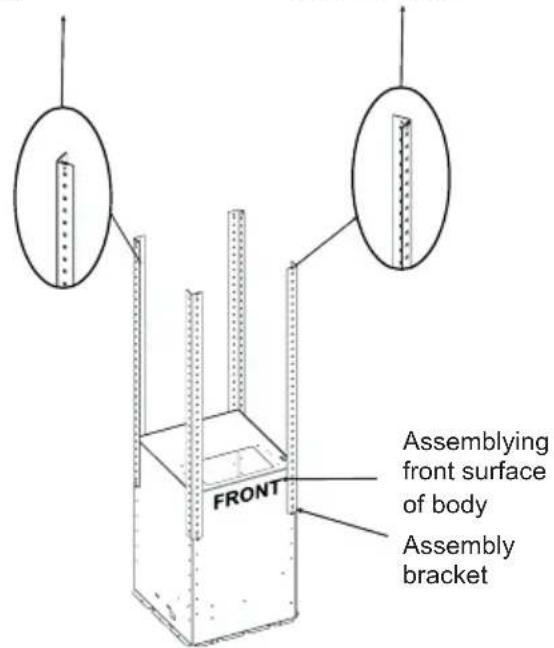
Pic. 4
natural_image
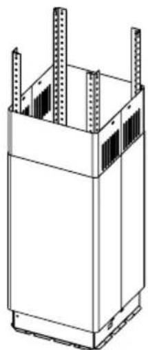
Technical line drawing of a rectangular enclosure with vertical supports and internal compartments (no text or symbols)Pic. 5a Pic. 5b

natural_image
Pure technical line drawing of a corner joint or bracket (no text or symbols)D) Placing Motor Cabin to Hanging Bar
Place fixed hanging sticks on hanging bar through the channels. Fix parts together via 3,5x9,5 screws (Picture 7).
natural_image
Technical line drawing of a mechanical structure with vertical supports and a shaded internal component (no text or symbols)Pic. 8
natural_image
Line drawing of a hand using a tool to adjust or install a metal bracket structure (no text or symbols)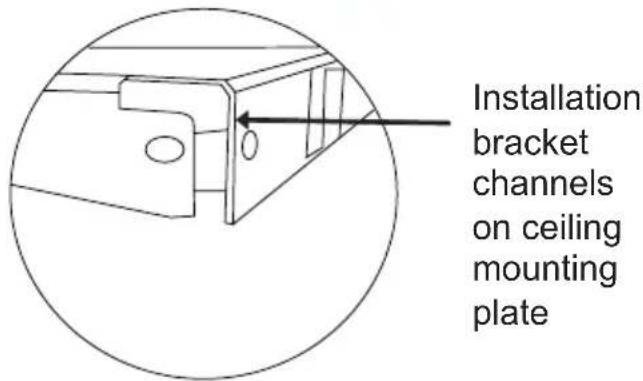
Pic. 7
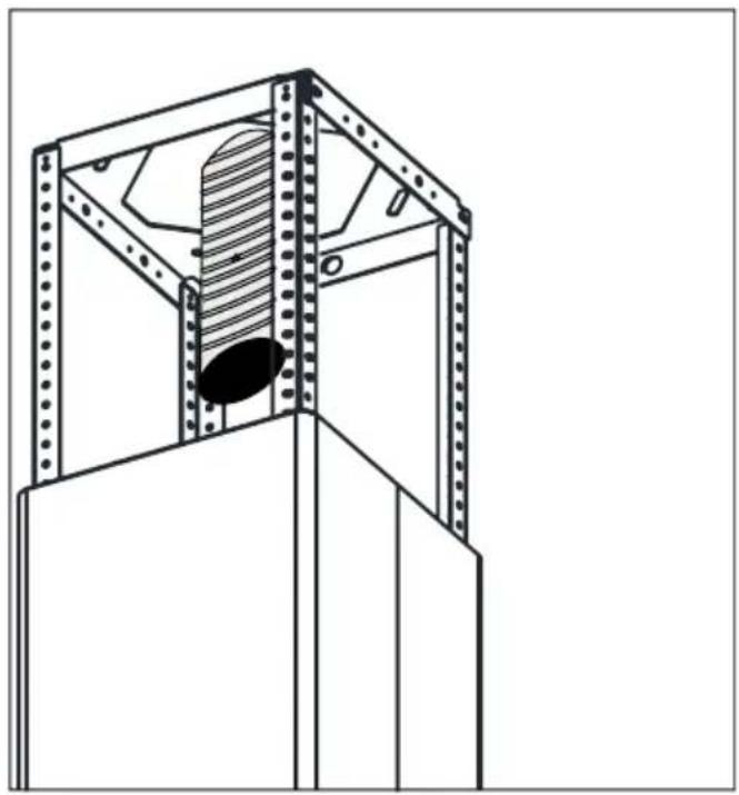
E) Installing Aluminum Flexible Pipe
Connect aluminum flexible pipe to outlets on the product and kitchen wall. Ensure connection will not lose while your product is operated on maximum airflow level (Picture 8).
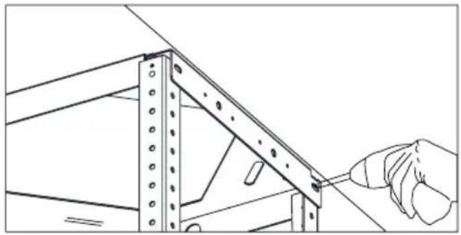
F) Metal frames installation
Using screws from installation kit, mount frames to hanging sticks (Pic. 9).
natural_image
Technical line drawing of a structural frame with vertical supports and a central oval opening (no text or symbols)Fig. 9
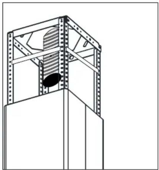
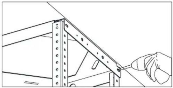
G) Fixing Internal Chimney
Pull internal chimney up, align holes and fix by 3,5x9,5 nickel coated screws as shown in Picture 10.
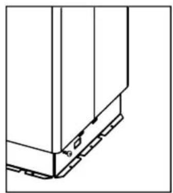
Assembling bracket hole on the Ceiling Connection Sheet
natural_image
Hand placing a component into a wall-mounted cabinet (no text or symbols visible)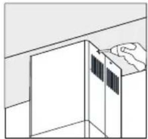
natural_image
Simple line drawing of a cabinet with a hand pointing to the top panel (no text or symbols)Pic. 10
natural_image
Line drawing of two hands holding a rectangular object with a downward arrow, no text or symbols presentPic.11
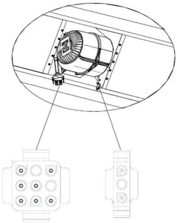
I) Fixing Motor Cabin on Product Body
Place hanging hooks on product body onto channels on motor cabin. Fix them together with 3,5x9,5 screws (Picture 12a-12b)
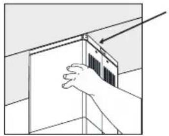
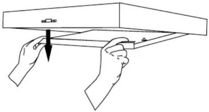
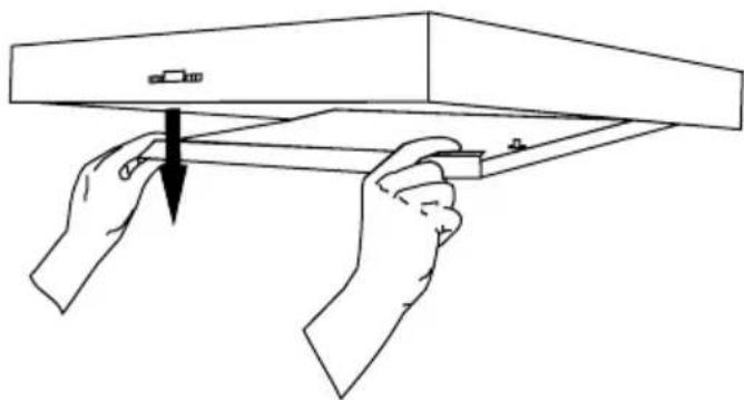
H) Removing split extraction plate
To remove split extraction plate, pull it down holding left and right upper points - Picture. 11.
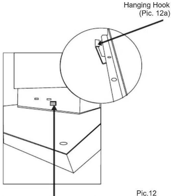
Hanging hook channel on motor cabin (Picture 12b)
INSTALLATION
natural_image
Line drawing of a hand using a tool to adjust or install a component, no text or symbols presentPic.13
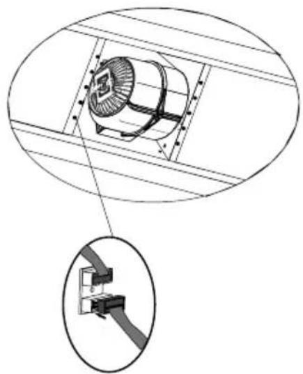
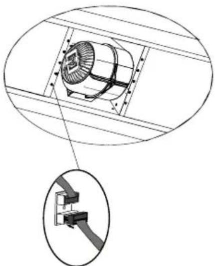
K) Making Connections
Connect 220V power supply socket with corresponding motor socket. Place aluminum cassette filters when connections are done. (Picture 14)
natural_image
Technical diagram of a fan installation with an inset close-up showing the cable attachment (no text or symbols)Pic.15
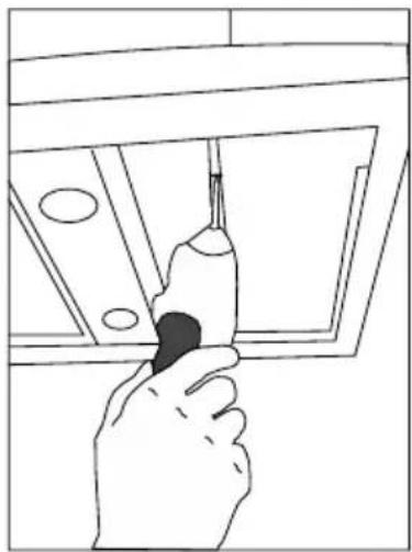
J) Fixing Motor Cabin on Product Body (2)
Using 3,5 x 9,5mm bolts mount both elements (Pic. 13).
natural_image
Technical line drawing of a mechanical device with two views (top and side), no text or symbols present.Pic.14
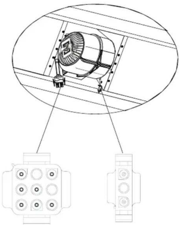
L) Making Connections (2)
Connect white plug (supply) into the correct socket. Picture 15
Use control panel to control your cooker hood (Pic. 4a)
OPERATION
Control Panel
The appliance has 3 fan speeds. Depending on cooking intensity and the amount of steam, you can choose low, medium or high fan speed. Buttons on the front panel are used for turning the appliance on.
To remove any residual odours and vapour from the kitchen it is recommended to use this function of the hood for several minutes after cooking.
Light
Your cooker hood features LED light. Press the " 🔥" button on the control panel (Pic. 4a) to turn the light on or off.
Regular maintenance and cleaning of the device will ensure faultless operation, and help extend the life of the unit. Attention should be paid to replacing grease and carbon filters according to instructions.
Aluminium grease filter
Cleaning
Clean the filter when the display shows “” approximately every 2-3 weeks.
To clear the above symbol (once the filter is cleaned and re-installed), hold the “” button for 3 seconds (make sure the hood is not operating). “E” symbol will be shown on the display and the appliance will operate normally.
If you want to use your appliance while the “C” symbol is still displayed, press the “☐” button. The speed indication will appear for 1 second, and then the “C” symbol and the motor will keep running.
NOTE: The "C" symbol appears after 60 hours of the motor operation.
Clean the grease filter by washing it in a dishwasher (maximum washing temperature of 60^ C) or by hand using a mild detergent or soap.
To replace:
Dismantling of aluminium grease filter is shown on Figure 5.
Acrylic filter is used in some models. This filter should be replaced at least once every two months or more frequently if the appliance is used intensively.
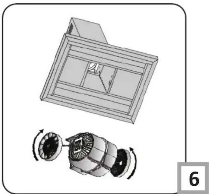
Charcoal filter (only the recirculation version)
Operation - Carbon filters can be used only when the hood is not connected to any ventilation duct. Filters with active carbon can absorb odours until they are saturated. They cannot be washed or regenerated and should be replaced at least every 2 months or more frequently in case of very intensive use.
Replace:
Dismantling of charcoal filter is shown on Figure 6.
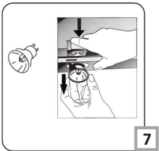
Lighting
See Figure 7 for details how to replace lights. Use incandescent / halogen / LED modules of the same specification as those factory-installed in the appliance.
Cleaning
Normal hood cleaning:
- Do not use a soaked cloth, sponge, or water jet.
- Do not use solvents or alcohol, as they may tarnish lacquered surfaces.
- Do not use caustic substances, especially for cleaning stainless steel.
- Do not use a rough or abrasive cloth.
It is recommend to use a damp cloth and a neutral detergent.
Aluminium filters may be washed in the dishwasher. The colour of aluminium filters may change after several washings. This is normal and it is not necessary to renew the filters.

RECYCLING OF THE PACKAGING

natural_image
Simple line drawing of a three chasing recycling symbol (no text or labels)Our packaging is made of environmentally friendly materials, which can be reused:
● The external packaging is made of cardboard/foil
● The FCKW free shape of foamed polystyrene (PS)
● Polyethylene (PE) foils and bags
ELIMINATION / DISPOSAL OF THE EU-IPMENT
If the appliance is no longer in use, cut the connecting cable off the used equipment before scrapping. We also recommend that the appliance is locked or render it useless so that the appliance presents no danger to children while being stored for disposal. This appliance is marked with a symbol of the crossed out waste container in conformance with the European Directive 2002/96/EC. Such

marking informs that the equipment may not be kept together with other waste coming from the household after the period of its use. The user is obliged to dispose of the appliance at the waste collection point authorised by the local authority. The local waste collection points, shops and communal units form an appropriate system enabling the disposal of the equipment.
Handling the used electrical and electronic equipment and any hazardous substances contained therein in a correct manner is vital to avoid damage the local natural environment. Therefore care and responsibility should always be taken in the disposal of these products
Manufacturer's Declaration
The manufacturer hereby declares that this product meets the requirements of the following European directives:
• Low Voltage Directive 2014/35/EC
• Electromagnetic Compatibility (EMC) Directive 2014/30/EC
• ErP Directive 2009/125/EC
• Directive RoHS 2011/65/EC
and has thus been marked with the symbol and been issued with a declaration of compliance made available to market regulators.
TIL LYKKE MED DIT NYE GRAM EMFANG
natural_image
Line drawing of a hand holding a tool interacting with a mechanical component (no text or symbols)Billede 5
natural_image
Technical line drawing of a rectangular industrial container with vertical supports (no text or symbols)natural_image
Pure technical line drawing of a corner joint or bracket (no text or symbols)natural_image
Technical line drawing of a mechanical structure with vertical supports and internal components (no text or symbols)Billede 7
natural_image
Line drawing of a hand using a tool to adjust or install a metal bracket structure (no text or symbols)
natural_image
Technical line drawing of a mechanical bracket with an arrow indicating direction (no text or symbols)natural_image
Technical line drawing of a mechanical lifting frame structure (no text or symbols)Billede 8
natural_image
Two technical diagrams showing hand positioning of a cabinet with an arrow indicating direction (no text or symbols present)Fig. 9
natural_image
Line drawing of two hands holding a rectangular object with a downward arrow, no text or symbols presentBillede 10
natural_image
Technical line drawing of a mechanical assembly with an inset magnified detail showing a bracket detail (no text or symbols)natural_image
Line drawing of a hand using a screwdriver to adjust or install a component on a machine (no text or symbols)Billede 12
K) Tilslutning til lysnettet
natural_image
Technical diagram of a fan installation with an inset close-up showing a bracket (no text or symbols present)Billede 14
natural_image
Technical line drawing of a mechanical device with two inset views showing internal components (no text or symbols)Billede 13
natural_image
Simple line drawing of a recycling symbol (three chasing arrows), no text or labels present.natural_image
Line drawing of a hand holding a tool interacting with a mechanical component (no text or symbols)natural_image
Technical line drawing of a rectangular enclosure with vertical supports and internal compartments (no text or symbols)Kuva 5a Kuva 5b
natural_image
Pure technical line drawing of a corner joint or bracket (no text or symbols)natural_image
Technical line drawing of a structural frame with vertical supports and a central oval component (no text or symbols)Kuva 8

natural_image
Line drawing of a hand using a tool to adjust or install a metal bracket structure (no text or symbols)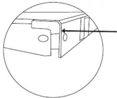
natural_image
Technical line drawing of a mechanical bracket with a circular cross-section view (no text or symbols)natural_image
Technical line drawing of a structural frame with vertical supports and a central oval opening (no text or symbols)Kuva 9
natural_image
Hand placing a wall-mounted panel with a directional arrow (no text or symbols)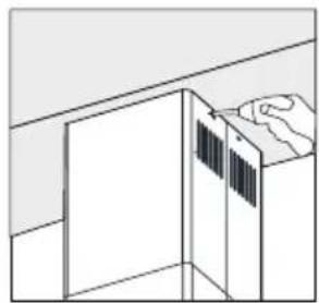
natural_image
Simple line drawing of a cabinet with a hand pointing to the top panel (no text or symbols)Kuva 10

natural_image
Line drawing of two hands holding a rectangular object with a downward arrow, no text or symbols presentKuva 11
natural_image
Line drawing of a hand using a screwdriver to adjust or install a component on a machine (no text or symbols)Kuva 13
K) Liitännät
natural_image
Technical diagram of a fan installation with structural beams and a close-up view of the component (no text or symbols)Kuva 15
natural_image
Technical line drawing of a mechanical device with two views of its internal components (no text or symbols)Kuva 14
L) Liitännät (2)
natural_image
Simple line drawing of a three chasing recycling symbol (no text or labels)TACK FÖR ATT DU HAR KÖPT EN GRAM-PRODUKT
BÄSTA KUND!
INNEHÅLLSFÖRTECKNING
SÄKERHETSANVISNINGAR 41
INSTALLATION 44
ANVÄNDNING OCH SKÖTSEL 49
MILJÖSKYDD 51

natural_image
Line drawing of a hand holding a tool interacting with a mechanical component (no text or symbols)Bild 5
natural_image
Technical line drawing of a rectangular enclosure with vertical supports and internal compartments (no text or symbols)Bild 5a Bild 5b

natural_image
Pure technical line drawing of a corner joint or bracket (no text or symbols)natural_image
Technical line drawing of a mechanical lifting frame with a central oval component (no text or symbols)Bild 8
natural_image
Line drawing of a hand using a tool to adjust or install a metal bracket structure (no text or symbols)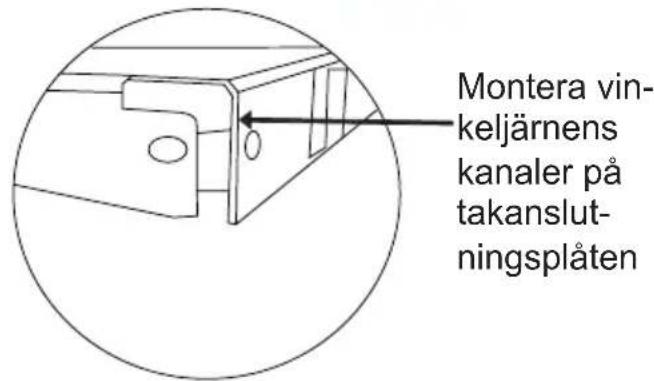
natural_image
Technical line drawing of a structural frame with vertical supports and a central oval component (no text or symbols)Bild 9
G) Fixera den inre skorstenen
natural_image
Hand placing a component into a wall-mounted cabinet (no text or symbols visible)
natural_image
Simple line drawing of a cabinet with a hand pointing to the top panel (no text or symbols)Blid.10

natural_image
Line drawing of two hands holding a rectangular object with a downward arrow, no text or symbols presentBild 11
H) Ta bort den delade utsugspanelen
natural_image
Technical line drawing of a mechanical assembly with an inset magnified detail showing a bracket detail (no text or symbols)natural_image
Line drawing of a hand using a tool to adjust or install a component, labeled 'Bild 13' (no other text or symbols)K) Anslutning
natural_image
Technical diagram of a fan installation with structural beams and a close-up view of the component (no text or symbols)Bild 15
natural_image
Technical line drawing of a mechanical device with two views (top and side), no text or symbols present.Bild 14
L) Anslutning (2)
Anslut den vita kontakten (strömmatning) till korrekt uttag. Bild 15
natural_image
Simple line drawing of a recycling symbol (three chasing arrows), no text or labels present.TAKK FOR AT DU KJ∅PTE ET GRAM-PRODUKT
KJÆRE KUNDE!
BRUK OG VEDLIKEHOLD 61
MILJ∅VERN 63

natural_image
Line drawing of a hand holding a tool interacting with a mechanical component (no text or symbols)bilde 5
natural_image
Technical line drawing of a rectangular electrical enclosure with vertical posts and base (no text or symbols)bilde 5a bilde 5b

natural_image
Pure technical line drawing of a corner joint or bracket (no text or symbols)MONTERING
D) Fest motorkabinettet til hengestangen
natural_image
Technical line drawing of a mechanical lifting frame with a central component (no text or symbols)bilde 7
natural_image
Line drawing of a hand using a tool to adjust or install a metal bracket (no text or symbols present)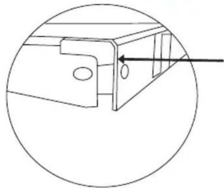
natural_image
Technical line drawing of a mechanical bracket with a circular cross-section view (no text or symbols)natural_image
Technical line drawing of a structural frame with vertical supports and a central oval opening (no text or symbols)bilde 9
G) Fest innvendig pipe
natural_image
Line drawing of two hands holding a rectangular object with a downward arrow, no text or symbols presentbilde 11
natural_image
Technical line drawing of a cabinet or enclosure with an inset magnified detail showing a bracket and mounting points (no text or symbols)natural_image
Line drawing of a hand using a tool to adjust or install a component, no text or symbols presentBilde 13
K) Koble til
Koble 220V stikkontakt med tilsvarende motorkontakt. Sett i aluminiumkassettfiltre när tilkoblingene er gjort. (Bilde 14)
natural_image
Technical diagram of a fan assembly with an inset close-up showing a mounted bracket (no text or symbols present)Bilde 15
J) Feste motorkabinen på skroget (2)
Bruk 3,5 x 9,5 mm bolter til å feste begge elementene (Bilde 13).
natural_image
Technical line drawing of a mechanical component with two views (top and side), no text or symbols present.Bilde 14